ecs mid atlantic, llc - loudoun
TRANSCRIPT

ECS Mid‐Atlantic, LLC Geotechnical Engineering Report
Ashburn Road Sidewalk Addition
Ashburn, Loudoun County, Virginia ECS Project Number 01:28838 April 10, 2019

April 10, 2019 Mr. Mark Hoffman, P.E. Loudoun County Department of Tansportation & Capital Infrastructure 101 Blue Seal Drive Suite 102 P.O. Box 7500 Leesburg, Virginia 20177
ECS Project No. 01:28838 Reference: Geotechnical Engineering Report
Ashburn Road Sidewalk Addition Ashburn Road Ashburn, Loudoun County, Virginia
Dear Mr. Hoffman: ECS Mid‐Atlantic, LLC (ECS) has completed the subsurface exploration, laboratory testing, and geotechnical engineering analyses for the above‐referenced project. Our services were performed in general accordance with the scope of work provided under our Proposal No. 01:58719‐GP, dated December 4, 2018, and Contract Amendment #3 Oncall Geotechnical Engineering and Soil Scientists Services dated June 26, 2018. This report presents our understanding of the geotechnical aspects of the project along with the results of the field exploration and laboratory testing conducted, and our design and construction recommendations. It has been our pleasure to be of service to Loudoun County during the design phase of this project. We would appreciate the opportunity to remain involved during the continuation of the design phase, and we would like to provide our services during construction phase operations as well to verify the assumptions of subsurface conditions made for this report. Should you have any questions concerning the information contained in this report, or if we can be of further assistance to you, please contact us. Respectfully submitted, ECS Mid‐Atlantic, LLC Sean D. Millar R. Drew Thomas, C.P.G. Senior Project Manager Principal Engineering Geologist [email protected] [email protected]
Ashburn Road Sidewalk Addition April, 10, 2018 ECS Project No. 01:28838 Page i
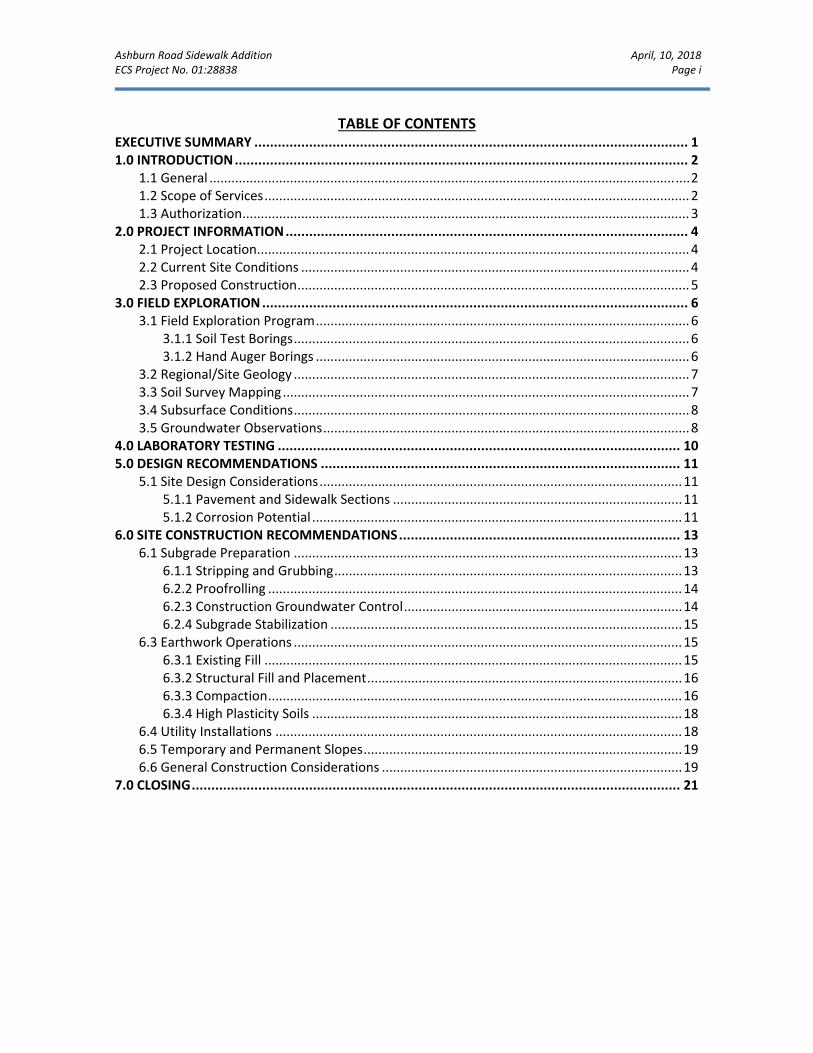
TABLE OF CONTENTS EXECUTIVE SUMMARY ............................................................................................................... 1 1.0 INTRODUCTION .................................................................................................................... 2
1.1 General ................................................................................................................................... 2 1.2 Scope of Services .................................................................................................................... 2 1.3 Authorization .......................................................................................................................... 3
2.0 PROJECT INFORMATION ....................................................................................................... 4 2.1 Project Location...................................................................................................................... 4 2.2 Current Site Conditions .......................................................................................................... 4 2.3 Proposed Construction ........................................................................................................... 5
3.0 FIELD EXPLORATION ............................................................................................................. 6 3.1 Field Exploration Program ...................................................................................................... 6
3.1.1 Soil Test Borings ............................................................................................................ 6 3.1.2 Hand Auger Borings ...................................................................................................... 6
3.2 Regional/Site Geology ............................................................................................................ 7 3.3 Soil Survey Mapping ............................................................................................................... 7 3.4 Subsurface Conditions ............................................................................................................ 8 3.5 Groundwater Observations .................................................................................................... 8
4.0 LABORATORY TESTING ....................................................................................................... 10 5.0 DESIGN RECOMMENDATIONS ............................................................................................ 11
5.1 Site Design Considerations ................................................................................................... 11 5.1.1 Pavement and Sidewalk Sections ............................................................................... 11 5.1.2 Corrosion Potential ..................................................................................................... 11
6.0 SITE CONSTRUCTION RECOMMENDATIONS ........................................................................ 13 6.1 Subgrade Preparation .......................................................................................................... 13
6.1.1 Stripping and Grubbing ............................................................................................... 13 6.2.2 Proofrolling ................................................................................................................. 14 6.2.3 Construction Groundwater Control ............................................................................ 14 6.2.4 Subgrade Stabilization ................................................................................................ 15
6.3 Earthwork Operations .......................................................................................................... 15 6.3.1 Existing Fill .................................................................................................................. 15 6.3.2 Structural Fill and Placement ...................................................................................... 16 6.3.3 Compaction ................................................................................................................. 16 6.3.4 High Plasticity Soils ..................................................................................................... 18
6.4 Utility Installations ............................................................................................................... 18 6.5 Temporary and Permanent Slopes ....................................................................................... 19 6.6 General Construction Considerations .................................................................................. 19
7.0 CLOSING ............................................................................................................................. 21

Ashburn Road Sidewalk Addition April, 10, 2018 ECS Project No. 01:28838 Page ii
APPENDICES Appendix A – Drawings & Reports
Site Vicinity Map
Boring Location Diagram
Geology Mapping Diagram
Soils Mapping Diagram Appendix B – Field Operations
Reference Notes for Boring Logs
Boring Logs B‐1 through B‐4
Hand Auger Log HA‐1 Appendix C – Laboratory Testing
Laboratory Test Results Summary
Liquid and Plastic Limits Test Report
Particle Size Distribution Report
Electrical Resistivity Test Report Appendix D – Supplemental Report Documents and Calculations
French Drain Installation Procedure
Ashburn Road Sidewalk Addition April, 10, 2018 ECS Project No. 01:28838 Page 1
EXECUTIVE SUMMARY The following summarizes the main findings of the exploration, particularly those that may have a cost impact on the planned development. Information gleaned from the executive summary should not be utilized in lieu of reading the entire geotechnical report. The project site is located along the eastern boundary of Ashburn Road between Hay Road and Partlow Road. The site currently includes a drainage ditch adjacent to the shoulder of the road section with curb and gutter at the entrance to 20800 Ashburn Road towards the northern end of the proposed sidewalk addition. The purpose of the exploration was to explore the conditions for the proposed sidewalk and associated stormwater inlets and 15” RCP and 30” RCP stormwater lines. The subsurface conditions for the proposed sidewalk addition were explored by drilling a total four (4) soil test borings, B‐1 through B‐4, along the alignment of the proposed sidewalk and associated storm water lines and one (1) hand auger (HA‐1) along the proposed alignment of the 30” stormwater line. The borings conducted reached the proposed depth of 10 feet below the surface at all locations with the exception of B‐1, B‐3 and HA‐1 which terminated at 7± feet, 7.1± feet and 4.6± feet, respectively. Up to approximately 2 inches of topsoil was encountered in Borings B‐1 through B‐4. Existing fill consisting of Lean CLAY (CL) and Clayey SAND (SC) was encountered in Borings B‐1 and B‐4 to approximately 2.5± feet below the existing ground surface. Beneath the cover material, the soil generally consisted of up to 5± feet of firm to stiff Lean CLAY underlain by very dense weathered siltstone. Based on the subsurface exploration completed we anticipate the site will be suitable for the proposed development. We do not anticipate conditions on the project site to adversely affect future development beyond the typical difficulties encountered in this geographic region (i.e., shallow bedrock and moisture sensitive soils).

Ashburn Road Sidewalk Addition April, 10, 2018 ECS Project No. 01:28838 Page 2
1.0 INTRODUCTION 1.1 GENERAL The purpose of this study was to provide geotechnical information for the sidewalk addition along the east side of Ashburn Road between approximately Partlow Drive and Hay Road. We understand that there is no existing sidewalk in this area. Current conditions include the road shoulder and ditch and curb and gutter roadway sections in select locations. The recommendations developed for this report are based on project information supplied by Loudoun County. This report contains the results of our subsurface explorations and laboratory testing programs, site characterization, engineering analyses, and recommendations for the design and construction of the proposed sidewalk improvements. 1.2 SCOPE OF SERVICES To obtain the necessary geotechnical information required for design of the proposed sidewalk addition, four soil test borings and one hand auger were performed at locations selected by ECS. These borings were located at regular intervals along the proposed sidewalk and stormwater inlets and along the alignment of the 15‐inch and 30‐inch stormwater lines. A laboratory testing program was also implemented to characterize the physical and engineering properties of the subsurface soils. This report discusses our exploratory and testing procedures, presents our findings and evaluations and includes the following.
A brief review and description of our field and laboratory test procedures and the results of testing conducted.
A review of surface topographical features and site conditions.
A review of area and site geologic conditions.
A review of subsurface soil stratigraphy with pertinent available physical properties.
Final logs of the soil test borings and hand auger boring records of the field exploration prepared in accordance with the standard practice for geotechnical engineering.
Recommendations for site preparation and construction of compacted fills, including an evaluation of on‐site soils for use as compacted fills and delineation of potentially unsuitable soils and/or soils exhibiting excessive moisture at the time of sampling.
Recommendations for sidewalk construction, including recommendations for subgrade improvements and subdrainage recommendations
General recommendations for pavement design, including a recommended design CBR value.
Evaluation and recommendations relative to groundwater control.
An evaluation of soil and rock excavation issues.

Ashburn Road Sidewalk Addition April, 10, 2018 ECS Project No. 01:28838 Page 3
1.3 AUTHORIZATION Our services were provided in accordance with our proposed scope of services outlined in our Proposal for Subsurface Exploration and Geotechnical Engineering, dated December 4, 2018, and as authorized by Loudoun County and Contract Amendment #3 Oncall Geotechnical Engineering and Soil Scientists Services.

Ashburn Road Sidewalk Addition April, 10, 2018 ECS Project No. 01:28838 Page 4
2.0 PROJECT INFORMATION 2.1 PROJECT LOCATION The site is located along the east side of Ashburn Road, between Partlow Road and Hay Road, in Ashburn, Loudoun County, Virginia. The project site is approximately 0.2 miles in length, and is currently the shoulder of the road with curb and gutter at select locations. Below is a Site Location figure depicting the general location of the project based on the description above for reference. A second Site Vicinity Map is included in the Appendix of this report that is “to‐scale” that meet Loudoun County Facilities Standards Manual (FSM) requirements.
Figure 2.1.1 Site Location
2.2 CURRENT SITE CONDITIONS The proposed site is currently at grade, lined on the east side with a grassed drainage ditch and the asphalt paving surface of Jenkins Lane and entrances to businesses along the northern portion of the new sidewalk area and single family residences along the southern portion of the new sidewalk area. Based on elevation data obtained from the Site Plan, prepared by Rinker Design Associates, P.C. dated November 8, 2018, the site has a topographic high of about EL. 293± feet along the northern end of the proposed sidewalk and a topographic low of about EL 282± feet at the southern end of the proposed sidewalk. Several utilities were located along the proposed sidewalk including communication lines, underground water, sanitary sewer, and gas laterals for the properties along the alignment.
Ashburn Road Sidewalk Addition April, 10, 2018 ECS Project No. 01:28838 Page 5
If any of the information is inaccurate, either due to misunderstanding or due to design changes that may occur later, ECS should be contacted in order to provide additional or alternate recommendations that may be required. The project boundaries, as well as the existing and proposed site features, are included on the diagrams included in Appendix A of this report. 2.3 PROPOSED CONSTRUCTION Based on the project site plans provided to us and prepared by Rinker Design Associates, P.C. dated November 8, 2018, we understand that the project will consist of the construction of approximately 0.2 miles of sidewalk, including stormwater inlets and stormwater lines, along the east side of Ashburn Road, approximately between Hay Road and Partlow Drive in Ashburn, Virginia. As part of construction, portions of the asphalt entrance to the property located at 20730 Ashburn Road will be removed. We have included general design recommendations for pavement and sidewalk construction. Based on the proposed topography information, we anticipate minimum cuts and fills required to reach the proposed subgrade elevation of the proposed sidewalk. The description of the proposed project is based on the information provided to us by your office or other design team members. If any of the information is inaccurate, either due to misunderstanding or due to design changes that may occur later, we recommend that we be contacted in order to provide additional or alternate recommendations that may be required.
Ashburn Road Sidewalk Addition April, 10, 2018 ECS Project No. 01:28838 Page 6
3.0 FIELD EXPLORATION 3.1 FIELD EXPLORATION PROGRAM
The field exploration was planned with the objective of characterizing the project site in general geotechnical and geological terms and to evaluate subsequent field and laboratory data to assist in the determination of geotechnical recommendations. The field exploration consisted of a series of soil test borings and hand auger borings. Boring locations were selected by ECS, and identified in the field by ECS personnel using GPS methods prior to mobilization of our drilling equipment. The approximate as‐drilled boring locations are shown on the Boring Location Diagram in Appendix A. Ground surface elevations noted on our boring logs were interpolated from the site plan provided by the Rinker Design Associates, P.C.
3.1.1 Soil Test Borings
The subsurface conditions were explored by drilling four soil test borings and one hand auger boring within the proposed project site. Based on existing site conditions, an all‐terrain vehicle (ATV)‐mounted drill rig was utilized to drill the soil test borings. Borings were advanced to depths of 7± feet to 10± feet below the ground surface, where auger refusal caused termination. Subsurface explorations were completed under the general supervision of an ECS geologist.
Boring locations were selected by ECS, and were located in the field by ECS representatives using GPS techniques prior to mobilization of our drilling equipment. The approximate as‐drilled boring locations are shown on the Boring Location Diagram in Appendix A. Ground surface elevations noted on our boring logs were interpolated from the site plan prepared by Rinker Design Associates, P.C., dated November 8, 2018.
Standard penetration tests (SPTs) were conducted in the soil test borings at regular intervals in general accordance with ASTM D 1586. SPTs were not performed in the hand auger boring. Small representative samples were obtained during these tests and were used to classify the soils encountered. The standard penetration resistances obtained provide a general indication of soil shear strength and compressibility.
3.1.2 Hand Auger Borings
At one location along the alignment for a proposed 30‐inch stormwater line, a hand auger boring was performed. The hand auger boring was advanced to a depth of 4.7± feet below the existing ground surface, and was terminated due to auger refusal on a dense rock or gravel layer. Subsurface explorations were completed under the general supervision of an ECS geologist.
A field log of the soils encountered in the borings was maintained by the field personnel. After recovery, each sample was removed from the hand auger and was visually classified. Representative portions of each sample were then sealed and brought to our laboratory in

Ashburn Road Sidewalk Addition April, 10, 2018 ECS Project No. 01:28838 Page 7
Chantilly, Virginia for further review and laboratory testing. Upon completion of the hand auger boring, the excavated soil material was tamped back into place, and any excess soils were spread over the area.
Given that manual boring equipment (hand augers) was utilized for a portion of the subsurface exploration, hand auger refusal may not be representative of the bedrock surface as defined when utilizing a traditional geotechnical drill rig. Additionally, full size earth excavation equipment will likely be able to excavate beyond our hand auger refusal depth.
3.2 REGIONAL/SITE GEOLOGY
The site is located within the central portion of the Culpeper Triassic Basin which extends from the Rapidan River near Madison, Virginia to just west of Frederick, Maryland. The Culpeper Basin is a structural trough, or half‐graben, that formed as a result of tensional tectonic activity during the Triassic Geologic Period (±250 million years ago). The tensional tectonic activity that formed the Culpeper Basin continued to form the current Atlantic Ocean. In the down dropped portion of the basin, a playa lake formed which was subsequently filled by erosional deposits primarily from the Blue Ridge to the west and, to a lesser extent, from the Piedmont to the east.
During sedimentation of the basin, the western border fault periodically reactivated which has led to the generally shallow (5°‐15°) westward dip of local strata observed today. After considerable sedimentation of the basin, border fault reactivation resulted in cyclic layers of basalt and sandstone rock along the western margin of the basin. Late in the formation of the basin, local tectonic activity occurred which caused the basin sediments to be intruded by igneous magma forming dikes, sills, and lopoliths of diabase granite bedrock.
The Geologic Map of Loudoun County, Virginia indicates that the site is underlain by the Balls Bluff Siltstone (TRbs). The residual soils that develop upon this geologic unit generally have low to moderate plasticity and low to moderate shrink/swell potential. Our observations of the samples recovered from our borings generally agree with the mapped geology. An overview of the general site geology is illustrated on the Geology Mapping Diagram in Appendix A of this report.
3.3 SOIL SURVEY MAPPING
The natural soils which have resulted from the in‐place physical and chemical weathering of the underlying bedrock are composed primarily of residual clayey or silty soils with increasing amounts of sand with depth. The granular nature of the residual soils generally increases with depth as does the percentage of rock fragments. These layers are termed weathered rock due to their rocklike structure but exhibit characteristics which qualify them as soil. The soil to rock transition in conglomerate lithology is generally abrupt.
In addition, we have also reviewed the available Loudoun County Soils Mapping. Table 3.3.1 briefly presents the pertinent characteristics of the soil types mapped at this site.

Ashburn Road Sidewalk Addition April, 10, 2018 ECS Project No. 01:28838 Page 8
Table 3.3.1 Soil Type Characteristics by Mapping Unit (per Loudoun County)
Mapping Unit
Soil Group Typical Terrain Parent Rock Problems/Limiting
Factors
Depth to
SHWT (in)
Soil Class
74B Ashburn Silt
Loam Sloping
Landscapes Siltstone
Wetness, Low Bearing Capacities
24‐40 II
78A Dulles Silt Loam
Nearly Level Landscapes
Siltstone and Shale
Low Soil Strength and Prolonged Perched
Water Table 10‐24 IV
According to the Loudoun County Soils Mapping, the site is generally in an area mapped with Class II to Class IV soils, corresponding to fair potential to very poor potential for general site development.
3.4 SUBSURFACE CONDITIONS
The soils identified in the attached boring logs are consistent with the regional geology and soils mapping. The predominant soil profile appears to have been derived from the in‐place physical and chemical weathering of the underlying siltstone. Our field exploration generally indicated up to approximately 2± inches of topsoil in the boring locations B‐1 through B‐4.
Existing fill was observed at Borings B‐1 and B‐4 to an approximate depth of 2.5± feet, which consisted of Lean CLAY (CL) and Clayey SAND with Gravel (SC). The natural residual soils that were encountered generally consisted of low to high plasticity Lean CLAY (CL) with varying amount of sand and gravel. Standard Penetration Test (SPT) N‐Values within these soils typically ranged between 4 and over 14 blows per foot (bpf) which corresponds to firm to stiff consistencies for cohesive soils and very loose to medium dense relative densities for non‐cohesive soils. For the purposes of this report, weathered rock is any residual soil material having an SPT blow count of 60 bpf or greater. Borings B‐2 and B‐4 were extended to the planned termination depth of 10 feet below existing grades; however, auger refusal was encountered at Borings B‐1 and B‐3 and hand auger HA‐1 to depths between 4.6± feet and 7.1± feet below existing grades.
Highly plastic soils were not encountered within the borings performed; although highly plastic soils were not encountered, they may be encountered in unexplored areas of the site or between sampled locations.
3.5 GROUNDWATER OBSERVATIONS
In auger drilling operations, water is not introduced into the boreholes, and groundwater position can often be determined by observing water flowing into the boreholes. Furthermore, visual observation of the soil samples retrieved during excavation operations can often be used in

Ashburn Road Sidewalk Addition April, 10, 2018 ECS Project No. 01:28838 Page 9
evaluating the groundwater conditions. Groundwater observations were made during soil test boring and hand auger operations and after completion of exploration operations at each exploration location. Groundwater was not encountered during exploration of any of the soil test borings; however, the groundwater was observed at a depth of 4± feet below ground surface at the hand auger borings performed during this geotechnical exploration.
Perched groundwater can develop in areas with shallow rock. Specifically, precipitation that enters the site, either directly or from overland flow, begins to percolate through the low to moderately permeable surficial soils. Once the water percolation reaches the bedrock, which is virtually impermeable, it perches and begins to flow at the interface of the rock and the soil and within the fractured surface of the bedrock. This groundwater flow continues down gradient, with the perched water table occasionally surfacing to form as springs and intermittent streams. The groundwater is related to precipitation, although springs may exist in the lower lying areas for extended periods of time without recharge from precipitation. Therefore, the groundwater conditions at this site are expected to be significantly influenced by surface water runoff, especially during high precipitation seasons.
The highest groundwater observations are normally encountered in the late winter and early spring. Variations in the location of the long‐term water table may occur as a result of changes in precipitation, evaporation, surface water runoff, and other factors not immediately apparent at the time of this exploration. The site may also be subject to severe desiccation during extended dry periods. Therefore, massive earthwork operations, especially in the winter and spring, are more likely to encounter difficulties with perched conditions than those operations undertaken in the summer or fall.

Ashburn Road Sidewalk Addition April, 10, 2018 ECS Project No. 01:28838 Page 10
4.0 LABORATORY TESTING
The laboratory testing performed by ECS for this project consisted of selected tests performed on samples obtained during our field exploration operations. The following paragraphs briefly discuss the results of the completed laboratory testing program. Classification and index property tests were performed on representative soil samples obtained from the test borings in order to aid in classifying soils according to the Unified Soil Classification System and to quantify and correlate engineering properties.
An experienced geotechnical engineer/engineering geologist visually classified each soil sample from the test borings on the basis of texture and plasticity in accordance with the Unified Soil Classification System (USCS) and ASTM D‐2488 (Description and Identification of Soils‐Visual/Manual Procedures). After classification, the geotechnical engineer/engineering geologist grouped the various soil types into the major zones noted on the boring logs in Appendix B. The group symbols for each soil type are indicated in parentheses following the soil descriptions on the boring logs. The stratification lines designating the interfaces between earth materials on the boring logs are approximate; in situ, the transitions may be gradual, rather than distinct.

Ashburn Road Sidewalk Addition April, 10, 2018 ECS Project No. 01:28838 Page 11
5.0 DESIGN RECOMMENDATIONS
5.1 SITE DESIGN CONSIDERATIONS
The site generally appears suitable for the design and construction of the proposed sidewalk addition. The primary factors that could affect the proposed development are the presence of existing undocumented fill, a shallow rock surface, and the possibility of perched groundwater conditions. More detailed analysis and recommendations are included in the following sections.
5.1.1 Pavement and Sidewalk Sections
For the design and construction of sidewalks, we recommend that any soft or unsuitable materials be removed from the area extending to a minimum of 6‐inches beyond the edge of sidewalk outward from the road. The stripped surface should be proofrolled or probed and carefully observed at the time of construction in order to aid in identifying the localized soft or unsuitable materials, which should be removed. In addition, guidelines set forth in the sections entitled Subgrade Preparation and Earthwork Operations should be followed.
Subgrade Characteristics: Based on the results of our borings, it appears that the soils that will be exposed as sidewalk subgrades, exposed in cuts and placed as fill, will consist mainly of Lean CLAY (CL) with varying amounts of sand and gravel. As no CBR tests have been conducted at the time of the preparation of this report, a CBR value of 4 and a Resiliency Factor (RF) of 1.0 have been selected for preliminary design purposes,. The pavement design assumes subgrades consist of suitable materials evaluated by ECS and placed and compacted to at least 95 percent of the maximum dry density as determined by the Standard Proctor test (ASTM D 698) in accordance with the project specifications. Removal of highly plastic soils will be required as described below. It is recommended that CBR testing of the upper 12 inches of soils should occur during construction to obtain more accurate CBR values for this project.
Highly Plastic Soils: Highly plastic soils were not encountered in test locations. If highly plastic soils are encountered at the pavement or sidewalk subgrade, the highly plastic soils should be removed to a depth of 2 feet below the subgrade elevation or the thickness of the highly plastic soils, whichever is less.
Weather Restrictions: In this region, asphalt plants may close during the months of December, January, and/or February if particularly cold weather conditions prevail. However, this can change based on year to year temperature fluctuations. Daily temperatures from December to February will often stay below 40°F, limiting the days that asphalt placement can occur. Measures to protect fresh concrete from cold temperatures during curing will be required.
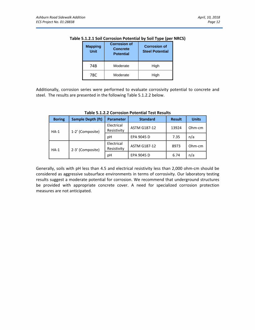
5.1.2 Corrosion Potential
Soil corrosion potential was evaluated based on the NRCS mapping database for corrosion potential of both concrete and steel. These risk potentials are summarized in Table 5.1.2.1 below. Based on the mapped results, the soils encountered on site are considered to exhibit a moderate concrete corrosion potential, and high steel corrosion potential; therefore, it is our opinion that underground concrete and metal structures should be provided with suitable corrosion protection.
Ashburn Road Sidewalk Addition April, 10, 2018 ECS Project No. 01:28838 Page 12
Table 5.1.2.1 Soil Corrosion Potential by Soil Type (per NRCS)
Mapping Unit
Corrosion of Concrete Potential
Corrosion of Steel Potential
74B Moderate High
78C Moderate High
Additionally, corrosion series were performed to evaluate corrosivity potential to concrete and steel. The results are presented in the following Table 5.1.2.2 below.
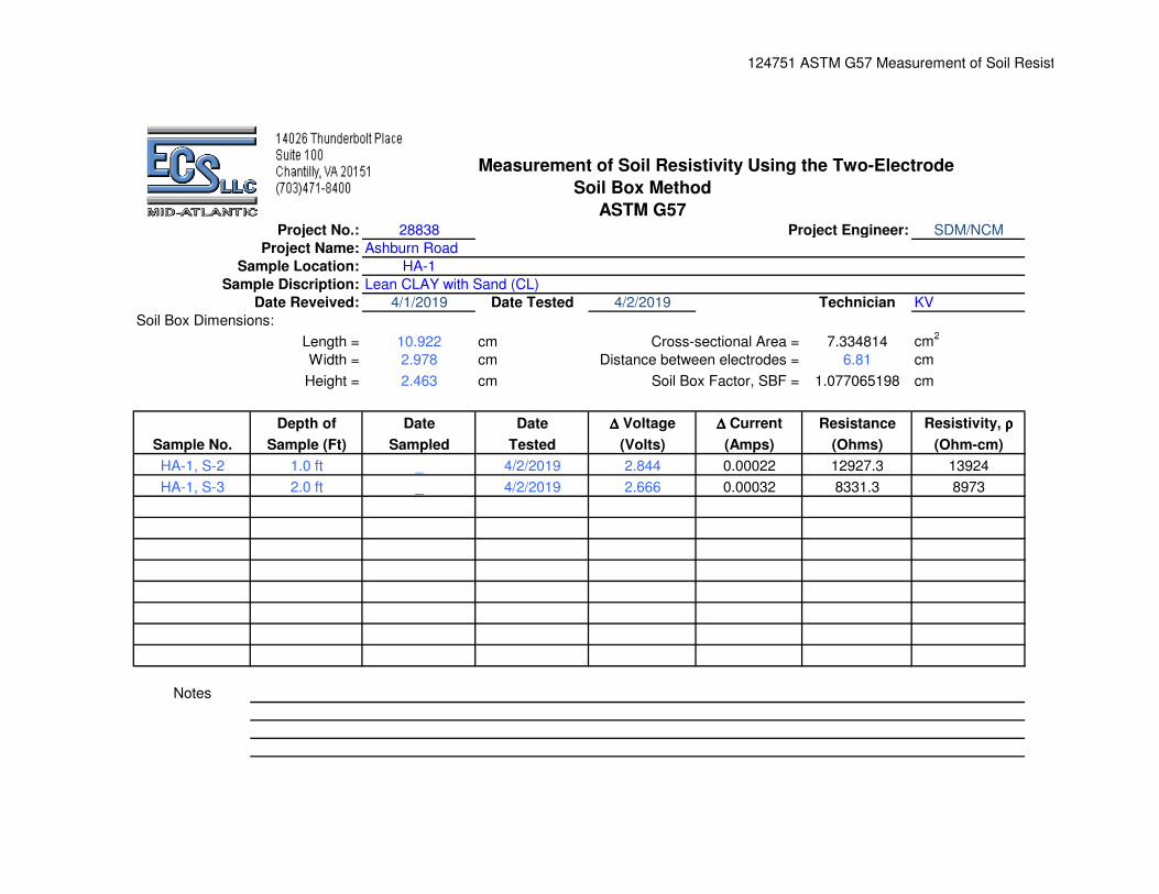
Table 5.1.2.2 Corrosion Potential Test Results
Boring Sample Depth (ft) Parameter Standard Result Units
HA‐1 1‐2’ (Composite)
Electrical Resistivity
ASTM G187‐12 13924 Ohm‐cm
pH EPA 9045 D 7.35 n/a
HA‐1 2‐3’ (Composite)
Electrical Resistivity
ASTM G187‐12 8973 Ohm‐cm
pH EPA 9045 D 6.74 n/a
Generally, soils with pH less than 4.5 and electrical resistivity less than 2,000 ohm‐cm should be considered as aggressive subsurface environments in terms of corrosivity. Our laboratory testing results suggest a moderate potential for corrosion. We recommend that underground structures be provided with appropriate concrete cover. A need for specialized corrosion protection measures are not anticipated.

Ashburn Road Sidewalk Addition April, 10, 2018 ECS Project No. 01:28838 Page 13
6.0 SITE CONSTRUCTION RECOMMENDATIONS 6.1 SUBGRADE PREPARATION 6.1.1 Stripping and Grubbing The subgrade preparation should consist of stripping all surface cover materials, topsoil, and any other soft or unsuitable material from the proposed pavement and sidewalk limits. We recommend that site stripping depths account for the topsoil and possible variations in topsoil thickness between boring locations. We recommend the earthwork clearing be extended a minimum of 5 feet beyond the pavement and sidewalk limits where practical. Stripping limits should be extended an additional 1 foot for each foot of fill required at the pavement and sidewalk exterior edges. The limits discussed in this paragraph define the expanded construction limits. Care should be exercised during grading operations to separate highly plastic soils, if encountered, from other suitable soils to reduce the potential for mixing of suitable and unsuitable materials. It should be anticipated that undercutting of up to 2± feet in the vicinity of test locations B‐1 and B‐4 may be required to remove undocumented fill. Pockets of highly plastic soils remaining after grading operations, should be removed to the depths described in the Highly Plastic Soils section of this report. Care must be exercised to identify additional unsuitable materials, and cause their removal. Procedures such as proofrolling, observation, or test pitting operations may be utilized to assist in identifying the presence of unsuitable materials, as required. The preparation of fill subgrades, as well as proposed pavement subgrades should be observed on a full‐time basis. These observations should be performed by the GER, or their representative, to document the unsuitable materials that have been removed, and that the subgrade is suitable for support of the proposed construction and/or fills. Procedures such as proofrolling, observation, or test pitting operations may be utilized to assist in identifying the presence of unsuitable materials, as required. Pavement and sidewalk areas should be thoroughly evaluated with proofrolling at the time of construction to identify areas that may be unsuitable. We recommend that the GER or their authorized representative be present during initial stripping and during excavation to help in delineating suitable and unsuitable materials. Any unsuitable areas identified should be undercut and replaced with suitable fill material compacted as described in this report or otherwise remediated as directed by the GER. Soil bridging lifts within the expanded project limits should not be used. Any soft areas should be removed or stabilized in place with geosynthetics and engineered fill as necessary. Recommendations regarding in‐place stabilization of soft or unsuitable subgrade materials should be provided by the GER at the time of construction.
Ashburn Road Sidewalk Addition April, 10, 2018 ECS Project No. 01:28838 Page 14
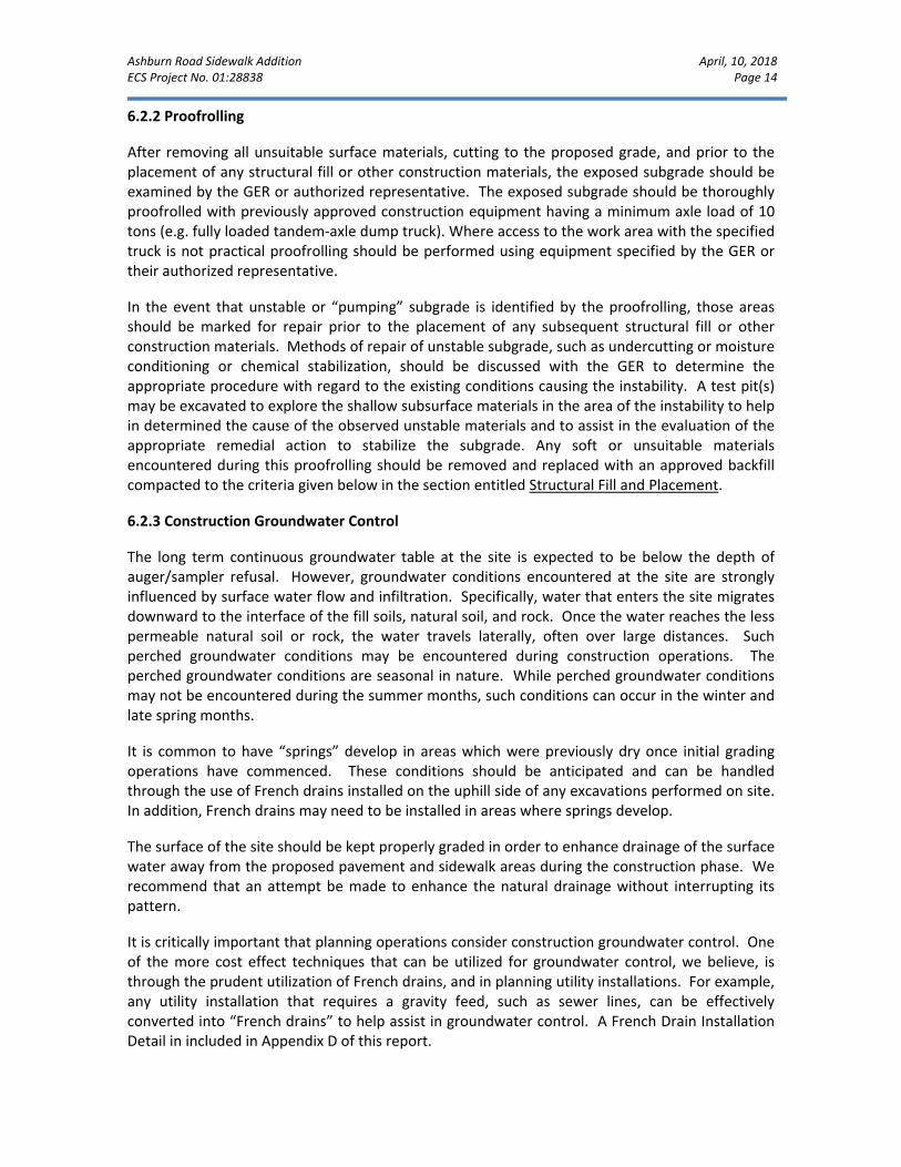
6.2.2 Proofrolling
After removing all unsuitable surface materials, cutting to the proposed grade, and prior to the placement of any structural fill or other construction materials, the exposed subgrade should be examined by the GER or authorized representative. The exposed subgrade should be thoroughly proofrolled with previously approved construction equipment having a minimum axle load of 10 tons (e.g. fully loaded tandem‐axle dump truck). Where access to the work area with the specified truck is not practical proofrolling should be performed using equipment specified by the GER or their authorized representative.
In the event that unstable or “pumping” subgrade is identified by the proofrolling, those areas should be marked for repair prior to the placement of any subsequent structural fill or other construction materials. Methods of repair of unstable subgrade, such as undercutting or moisture conditioning or chemical stabilization, should be discussed with the GER to determine the appropriate procedure with regard to the existing conditions causing the instability. A test pit(s) may be excavated to explore the shallow subsurface materials in the area of the instability to help in determined the cause of the observed unstable materials and to assist in the evaluation of the appropriate remedial action to stabilize the subgrade. Any soft or unsuitable materials encountered during this proofrolling should be removed and replaced with an approved backfill compacted to the criteria given below in the section entitled Structural Fill and Placement.
6.2.3 Construction Groundwater Control
The long term continuous groundwater table at the site is expected to be below the depth of auger/sampler refusal. However, groundwater conditions encountered at the site are strongly influenced by surface water flow and infiltration. Specifically, water that enters the site migrates downward to the interface of the fill soils, natural soil, and rock. Once the water reaches the less permeable natural soil or rock, the water travels laterally, often over large distances. Such perched groundwater conditions may be encountered during construction operations. The perched groundwater conditions are seasonal in nature. While perched groundwater conditions may not be encountered during the summer months, such conditions can occur in the winter and late spring months.
It is common to have “springs” develop in areas which were previously dry once initial grading operations have commenced. These conditions should be anticipated and can be handled through the use of French drains installed on the uphill side of any excavations performed on site. In addition, French drains may need to be installed in areas where springs develop.
The surface of the site should be kept properly graded in order to enhance drainage of the surface water away from the proposed pavement and sidewalk areas during the construction phase. We recommend that an attempt be made to enhance the natural drainage without interrupting its pattern.
It is critically important that planning operations consider construction groundwater control. One of the more cost effect techniques that can be utilized for groundwater control, we believe, is through the prudent utilization of French drains, and in planning utility installations. For example, any utility installation that requires a gravity feed, such as sewer lines, can be effectively converted into “French drains” to help assist in groundwater control. A French Drain Installation Detail in included in Appendix D of this report.

Ashburn Road Sidewalk Addition April, 10, 2018 ECS Project No. 01:28838 Page 15
If utilized, the French drain should consist of a filter fabric lined trench filled with No. 57 stone or equivalent open graded stone. After this installation has been completed, the filter fabric should be wrapped over the top of the gravel and pipe whereupon placement of fill may proceed to grade. 6.2.4 Subgrade Stabilization Subgrade Benching: Fill should not be placed on ground with a slope steeper than 5H:1V, unless the fill is confined by an opposing slope, such as in a ravine. Otherwise, where steeper slopes exist, the ground should be benched so as to allow for fill placement on a horizontal surface. Subgrade Compaction: Upon completion of subgrade documentation, the exposed subgrade within the 5‐foot expanded pavement and embankment limits should be moisture conditioned to within ‐1 and +3 % of the soil’s optimum moisture content and be compacted with suitable equipment (minimum 10‐ton roller) to a depth of 10 inches. Subgrade compaction within the expanded pavement and embankment limits should be to a dry density of at least 98% of the Standard Proctor maximum dry density (ASTM D698). Beyond these areas, compaction of at least 95% should be achieved. ECS should be called on to document that proper subgrade compaction has been achieved. Subgrade Compaction Control: The expanded limits of the proposed construction areas should be well defined, including the limits for pavements, fills, and slopes, etc. Field density testing of subgrades will be performed at frequencies in Table 6.1.
Table 6.2.4.1 Frequency of Subgrade Compaction Testing
Location Frequency of Tests
Pavement Areas 1 test per 10,000 sq. ft.
All Other Non‐Critical Areas 1 test per 15,000 sq. ft.
Subgrade Stabilization: In some areas, particularly low‐lying, wet areas of the site, undercutting of excessively soft materials may be considered inefficient. In such areas the use of a reinforcing geotextile or geogrid might be employed, under the advisement of ECS. Suitable stabilization materials may include medium duty woven geotextile fabrics or geogrids. The suitability and employment of reinforcing or stabilization products should be determined in the field by ECS personnel, in accordance with project specifications. 6.3 EARTHWORK OPERATIONS 6.3.1 Existing Fill Existing fills were encountered during our field exploration at Boring B‐1 and B‐4 to a depth of 2.5± feet below the current surface elevation. Based on the proximity of the site to the existing roadway and other adjacent areas of development, exisiting fills may be encountered in unexplored areas of the site. If existing fill soils are encountered during construction, they should be evaluated at that time by the GER or their representative. If no data exists regarding the placement, observation and testing of the existing fill to indicate it has been placed as structural
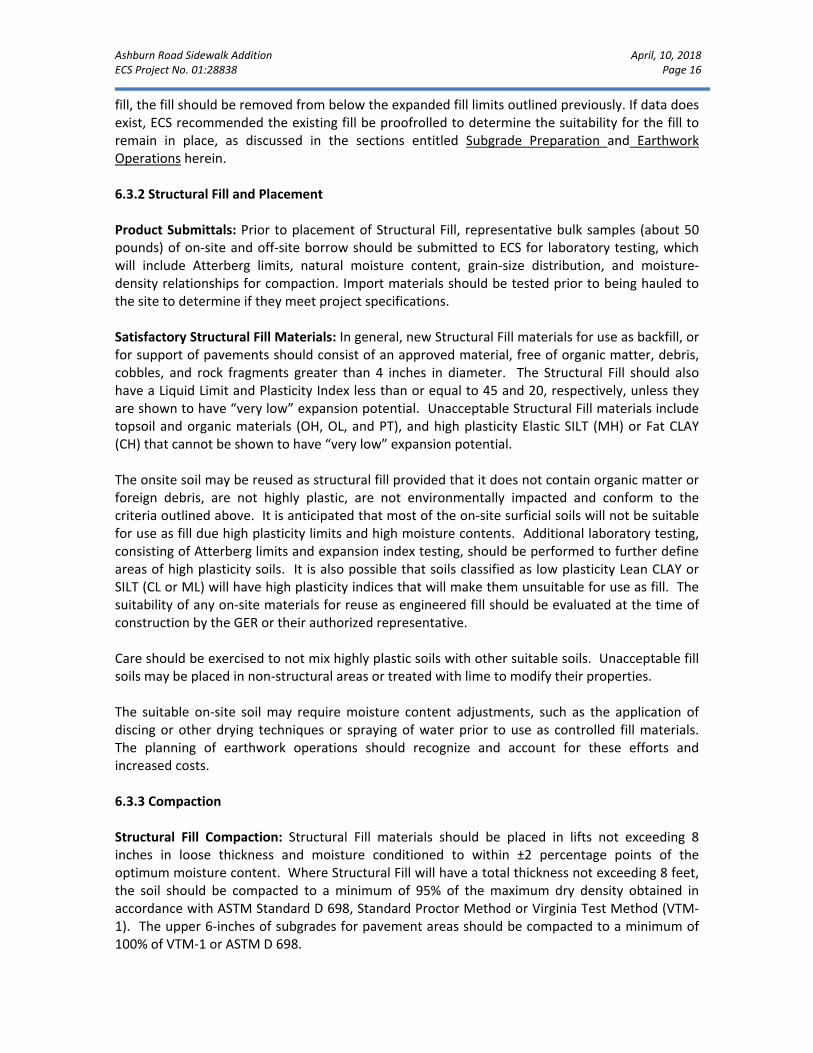
Ashburn Road Sidewalk Addition April, 10, 2018 ECS Project No. 01:28838 Page 16
fill, the fill should be removed from below the expanded fill limits outlined previously. If data does exist, ECS recommended the existing fill be proofrolled to determine the suitability for the fill to remain in place, as discussed in the sections entitled Subgrade Preparation and Earthwork Operations herein. 6.3.2 Structural Fill and Placement Product Submittals: Prior to placement of Structural Fill, representative bulk samples (about 50 pounds) of on‐site and off‐site borrow should be submitted to ECS for laboratory testing, which will include Atterberg limits, natural moisture content, grain‐size distribution, and moisture‐density relationships for compaction. Import materials should be tested prior to being hauled to the site to determine if they meet project specifications. Satisfactory Structural Fill Materials: In general, new Structural Fill materials for use as backfill, or for support of pavements should consist of an approved material, free of organic matter, debris, cobbles, and rock fragments greater than 4 inches in diameter. The Structural Fill should also have a Liquid Limit and Plasticity Index less than or equal to 45 and 20, respectively, unless they are shown to have “very low” expansion potential. Unacceptable Structural Fill materials include topsoil and organic materials (OH, OL, and PT), and high plasticity Elastic SILT (MH) or Fat CLAY (CH) that cannot be shown to have “very low” expansion potential. The onsite soil may be reused as structural fill provided that it does not contain organic matter or foreign debris, are not highly plastic, are not environmentally impacted and conform to the criteria outlined above. It is anticipated that most of the on‐site surficial soils will not be suitable for use as fill due high plasticity limits and high moisture contents. Additional laboratory testing, consisting of Atterberg limits and expansion index testing, should be performed to further define areas of high plasticity soils. It is also possible that soils classified as low plasticity Lean CLAY or SILT (CL or ML) will have high plasticity indices that will make them unsuitable for use as fill. The suitability of any on‐site materials for reuse as engineered fill should be evaluated at the time of construction by the GER or their authorized representative. Care should be exercised to not mix highly plastic soils with other suitable soils. Unacceptable fill soils may be placed in non‐structural areas or treated with lime to modify their properties. The suitable on‐site soil may require moisture content adjustments, such as the application of discing or other drying techniques or spraying of water prior to use as controlled fill materials. The planning of earthwork operations should recognize and account for these efforts and increased costs. 6.3.3 Compaction Structural Fill Compaction: Structural Fill materials should be placed in lifts not exceeding 8 inches in loose thickness and moisture conditioned to within ±2 percentage points of the optimum moisture content. Where Structural Fill will have a total thickness not exceeding 8 feet, the soil should be compacted to a minimum of 95% of the maximum dry density obtained in accordance with ASTM Standard D 698, Standard Proctor Method or Virginia Test Method (VTM‐1). The upper 6‐inches of subgrades for pavement areas should be compacted to a minimum of 100% of VTM‐1 or ASTM D 698.

Ashburn Road Sidewalk Addition April, 10, 2018 ECS Project No. 01:28838 Page 17
In any areas where the total depth of Structural Fill will exceed 8 feet, we recommend that these fill zones be placed as early as possible in the earthwork operations phase. Where the fill depth will be 8 feet or more, we recommend that the fill soils be compacted to a minimum of 98% of the maximum dry density obtained in accordance with ASTM D‐698 or VTM‐1, for the full depth of the fill. The purpose of the higher compaction criteria is to reduce differential settlement between natural cut soils and controlled fill soils.
Fill Compaction Control: The expanded limits of the proposed construction areas should be well defined, including the limits of the fill zones for pavements, retaining walls, and slopes, etc., at the time of fill placement. Grade controls should be maintained throughout the filling operations. All filling operations should be observed on a full‐time basis by a qualified representative of the construction testing laboratory to determine that the minimum compaction requirements are being achieved. Field density testing of fills will be performed at the frequencies shown in Table 6.3.3.1, but not less than 1 test per lift.
Table 6.3.3.1 Frequency of Compaction Tests in Fill Areas
Location Frequency of Tests
Pavement Areas 1 test per 10,000 sq. ft. per lift
Utility Trenches 1 test per 200 linear ft. per lift
All Other Non‐Critical Areas 1 test per 15,000 sq. ft. per lift
Compaction Equipment: Compaction equipment suitable to the soil type being compacted should be used to compact the subgrades and fill materials. Sheepsfoot compaction equipment should be suitable for the fine‐grained soils (Clays and Silts). A vibratory steel drum roller should be used for compaction of coarse‐grained soils (Sands) as well as for sealing compacted surfaces.
Fill Placement Considerations: Because of the moisture and disturbance sensitive nature of the silt and clay soils at the site, the initial 1 to 2 lifts of fill may need to be compacted without vibratory efforts. Vibratory compaction equipment may cause disturbance of the near surface site soil and upward migration of moisture into the engineered fill which could inhibit compaction efforts. After placement of the initial one to two lifts, vibratory compaction can proceed, if appropriate.
Fill materials should not be placed on frozen soils, on frost‐heaved soils, and/or on excessively wet soils. Borrow fill materials should not contain frozen materials at the time of placement, and all frozen or frost‐heaved soils should be removed prior to placement of Structural Fill or other fill soils and aggregates. Excessively wet soils or aggregates should be scarified, aerated, and moisture conditioned.
At the end of each work day, all fill areas should be graded to facilitate drainage of any precipitation and the surface should be sealed by use of a smooth‐drum roller to limit infiltration of surface water. During placement and compaction of new fill at the beginning of each workday, the Contractor may need to scarify existing subgrades to a depth on the order of 4 inches so that a weak plane will not be formed between the new fill and the existing subgrade soils.
Drying and compaction of wet soils is typically difficult during the cold, winter months. Accordingly, earthwork should be performed during the warmer, drier times of the year, if practical. Proper drainage should be maintained during the earthwork phases of construction to

Ashburn Road Sidewalk Addition April, 10, 2018 ECS Project No. 01:28838 Page 18
prevent ponding of water which has a tendency to degrade subgrade soils. Alternatively, if these soils cannot be stabilized by conventional methods as previously discussed, additional modifications to the subgrade soils such as lime or cement stabilization may be utilized to adjust the moisture content. If lime or cement are utilized to control moisture contents and/or for stabilization, Quick Lime, Calciment® or regular Type 1 cement can be used. The construction testing laboratory should evaluate proposed lime or cement soil modification procedures, such as quantity of additive and mixing and curing procedures, before implementation. The contractor should be required to minimize dusting or implement dust control measures, as required. Where fill materials will be placed to widen existing embankment fills, or placed up against sloping ground, the soil subgrade should be scarified and the new fill benched or keyed into the existing material (see VDOT Road and Bridge Specification Section 303.04(h)). Fill material should be placed in horizontal lifts. In confined areas such as utility trenches, portable compaction equipment and thin lifts of 3 inches to 4 inches may be required to achieve specified degrees of compaction. We recommend that the grading contractor have equipment on site during earthwork for both drying and wetting fill soils. We do not anticipate significant problems in controlling moisture within the fill during dry weather, but moisture control may be difficult during winter months or extended periods of rain. The control of moisture content of higher plasticity soils is difficult when these soils become wet. Further, such soils are easily degraded by construction traffic when the moisture content is elevated. 6.3.4 High Plasticity Soils High plasticity Fat CLAY (CH) was not encountered in the borings performed for this project. Highly plastic soils are not typically encountered in areas underlain by siltstone bedrock. Although highly plastic soils were not encountered in our borings, they may be encountered in unexplored areas or between sampled locations. These soils can develop significant shrink/swell problems with variations in moisture content. If the field work is conducted during the winter or early spring months, it is expected that even the non‐plastic clay soils at the surface may need to be removed or dried prior to fill placement. As earthwork operations proceed, additional Atterberg Limits and Expansion Index tests are recommended in order to evaluate suitability of questionable on‐site soils. High plasticity soils that cannot be shown to have “very low” expansion potential should be dealt with in accordance with the recommendations presented below. If highly plastic soils are encountered at the pavement or sidewalk subgrades they should be undercut to 2 feet below subgrade, or the thickness of the layer, whichever is less, and backfilled with structural fill. 6.4 UTILITY INSTALLATIONS Utility Subgrades: The soils encountered in our exploration are expected to be generally suitable for support of utility pipes. The pipe subgrade should be observed and probed for stability by ECS to evaluate the suitability of the materials encountered. Any loose or unsuitable materials encountered at the utility pipe subgrade elevation should be removed and replaced with suitable compacted Structural Fill or pipe bedding material.

Ashburn Road Sidewalk Addition April, 10, 2018 ECS Project No. 01:28838 Page 19
Utility Backfilling: The granular bedding material should be at least 4 inches thick, but not less than that specified by the project drawings and specifications. Fill placed for support of the utilities, as well as backfill over the utilities, should satisfy the requirements for Structural Fill given in this report. Compacted backfill should be free of topsoil, roots, ice, or any other material designated by ECS as unsuitable. The backfill should be moisture conditioned, placed, and compacted in accordance with the recommendations of this report. Utility Excavation Dewatering: It is possible that perched water may be encountered by utility excavations which extend below existing grades. It is expected that removal of perched water which seeps into excavations could be accomplished by pumping from sumps excavated in the trench bottom and which are backfilled with VDOT Size No. 57 stone or open graded bedding material. Should water conditions beyond the capability of sump pumping be encountered, the contractor should submit a Dewatering Plan in accordance with project specifications. Excavation Safety: All excavations and slopes should be made and maintained in accordance with OSHA excavation safety standards. The contractor is solely responsible for designing and constructing stable, temporary excavations and slopes and should shore, slope, or bench the sides of the excavations and slopes as required to maintain stability of both the excavation sides and bottom. The contractor’s responsible person, as defined in 29 CFR Part 1926, should evaluate the soil exposed in the excavations as part of the contractor’s safety procedures. In no case should slope height, slope inclination, or excavation depth, including utility trench excavation depth, exceed those specified in local, state, and federal safety regulations. ECS is providing this information solely as a service to our client. ECS is not assuming responsibility for construction site safety or the contractor’s activities; such responsibility is not being implied and should not be inferred. 6.5 TEMPORARY AND PERMANENT SLOPES Temporary fill slopes constructed of onsite native silty or clayey soils should be limited to a maximum gradient of approximately 2H:1V. The temporary slopes should also be thoroughly vegetated to help minimize erosion of the surficial soils. Temporary excavation slopes cut in the native soils should be no steeper than as indicated by OSHA and VOSHA protocol. Permanent slopes constructed of native soils should generally be 3H:1V or flatter. Slopes steeper than 3H:1V should be designed by the GER. Gradients as steep as 2H:1V may be achieved through the use of select aggregate or engineered rock fills, as well as through the installation of geosynthetics in native soils, but again, must be designed by the GER. Small landscape berms (less than 4 feet in height) may be as steep as 1H:1V but should be compacted as structural fill and thoroughly vegetated immediately upon completion. 6.6 GENERAL CONSTRUCTION CONSIDERATIONS Existing Fill: Existing fill was encountered during our recent exploration at Boring B‐1 and B‐4. Due to the proximity of existing roadways, utilities, and development, existing fill may be encountered in unexplored areas of the site. Existing fill material is likely not considered suitable for support of new construction, and will require reworking and replacement as controlled fill.

Ashburn Road Sidewalk Addition April, 10, 2018 ECS Project No. 01:28838 Page 20
Existing Utilities: Any existing utilities that are not planned to be reused should be removed, along with any unsuitable backfill materials, and capped at the property lines, or rerouted around the property and reconnected. The suitability of any existing utilities and utility trench backfill that will remain in place should be evaluated for structural support in the field by the GER. Care should be exercised during site grading operations so as not to damage any utilities that are to remain. Moisture Conditioning: During the cooler and wetter periods of the year, delays and additional costs should be anticipated. At these times, reduction of soil moisture may need to be accomplished by a combination of mechanical manipulation and the use of chemical additives, such as lime or cement, in order to lower moisture contents to levels appropriate for compaction. Alternatively, during the drier times of the year, such as the summer months, moisture may need to be added to the soil to provide adequate moisture for successful compaction according to the project requirements. Subgrade Protection: Measures should also be taken to limit site disturbance, especially from rubber‐tired heavy construction equipment, and to control and remove surface water from development areas, including structural and pavement areas. It would be advisable to designate a haul road and construction staging area to limit the areas of disturbance and to prevent construction traffic from excessively degrading sensitive subgrade soils and existing pavement areas. Haul roads and construction staging areas could be covered with excess depths of aggregate to protect those subgrades. The aggregate can later be removed and used in pavement areas. Surface Drainage: Surface drainage conditions should be properly maintained. Surface water should be directed away from the construction area, and the work area should be sloped away from the construction area at a gradient of 1 percent or greater to reduce the potential of ponding water and the subsequent saturation of the surface soils. At the end of each work day, the subgrade soils should be sealed by rolling the surface with a smooth drum roller to minimize infiltration of surface water. Excavation Safety: Cuts or excavations associated with utility excavations may require forming or bracing, slope flattening, or other physical measures to control sloughing and/or prevent slope failures. Contractors should be familiar with applicable OSHA codes to ensure that adequate protection of the excavations and trench walls is provided. Erosion Control: The surface soils may be erodible. Therefore, the Contractor should provide and maintain good site drainage during earthwork operations to maintain the integrity of the surface soils. All erosion and sedimentation controls should be in accordance with sound engineering practices and local requirements.

Ashburn Road Sidewalk Addition April, 10, 2018 ECS Project No. 01:28838 Page 21
7.0 CLOSING ECS has prepared this report of findings, evaluations, and recommendations to guide geotechnical‐related design and construction aspects of the project. The analysis and recommendations submitted in this report are based upon the data obtained from the soil borings and hand auger performed at the locations as indicated on the Boring Location Diagram and other information referenced in this report. This report does not reflect any variations that may occur between the test locations. In the performance of the subsurface exploration, specific information is obtained at specific locations at specific times. However, it is a well‐known fact that variations in soil and rock conditions exist on most sites between boring locations and also such situations as groundwater levels vary from time to time. The nature and extent of variations may not become evident until the course of construction. If variations then appear evident, it will become necessary for a reevaluation of the recommendations for this report after performing onsite observations during the construction period and noting the characteristics and variations. This report was prepared for the sole use of Loudoun County, and its consultants, the only intended beneficiaries of our work. The scope is limited to this specific project and locations described herein and our description of the project represents our understanding of the significant aspects relative to it. In the event of any change in the nature or location of the proposed construction outlined in this report or the accompanying plans and specifications, we should be informed so that the changes can be reviewed and the conclusions of this report modified or approved in writing by the design engineer. If any of this information is inaccurate, either due to our interpretation of the documents provided or site or design changes that may occur later, ECS should be contacted immediately in order that we can review the report in light of the changes and provide additional or alternate recommendations as may be required to reflect the proposed construction. We recommend that ECS be allowed to review the project’s plans and specifications pertaining to our work so that we may ascertain consistency of those plans/specifications with the intent of the geotechnical report. Field observations, monitoring, and quality assurance testing during earthwork and foundation installation are an extension of and integral to the geotechnical design recommendation. We recommend that the owner retain these quality assurance services and that ECS be allowed to continue our involvement throughout these critical phases of construction to provide general consultation as issues arise. ECS is not responsible for the conclusions, opinions, or recommendations of others based on the data in this report.

APPENDIX A – Drawings & Reports
Site Vicinity Map Boring Location Diagram Geology Mapping Diagram Soils Mapping Diagram


APPENDIX B – Field Operations
Reference Notes for Boring Logs Boring Logs B‐1 through B‐4
Hand Auger Log HA‐1

Reference Notes for Boring Logs (03-22-2017) © 2017 ECS Corporate Services, LLC. All Rights Reserved
COHESIVE SILTS & CLAYS
UNCONFINED
COMPRESSIVE
STRENGTH, QP4
SPT5
(BPF)
CONSISTENCY7
(COHESIVE)
<0.25 <3 Very Soft
0.25 - <0.50 3 - 4 Soft
0.50 - <1.00 5 - 8 Firm
1.00 - <2.00 9 - 15 Stiff
2.00 - <4.00 16 - 30 Very Stiff
4.00 - 8.00 31 - 50 Hard
>8.00 >50 Very Hard
GRAVELS, SANDS & NON-COHESIVE SILTS
SPT5
DENSITY
<5 Very Loose
5 - 10 Loose
11 - 30 Medium Dense
31 - 50 Dense
>50 Very Dense
REFERENCE NOTES FOR BORING LOGS
1Classifications and symbols per ASTM D 2488-09 (Visual-Manual Procedure) unless noted otherwise.
2To be consistent with general practice, “POORLY GRADED” has been removed from GP, GP-GM, GP-GC, SP, SP-SM, SP-SC soil types on the boring logs.
3Non-ASTM designations are included in soil descriptions and symbols along with ASTM symbol [Ex: (SM-FILL)].
4Typically estimated via pocket penetrometer or Torvane shear test and expressed in tons per square foot (tsf).
5Standard Penetration Test (SPT) refers to the number of hammer blows (blow count) of a 140 lb. hammer falling 30 inches on a 2 inch OD split spoon sampler required to drive the sampler 12 inches (ASTM D 1586). “N-value” is another term for “blow count” and is expressed in blows per foot (bpf).
6The water levels are those levels actually measured in the borehole at the times indicated by the symbol. The measurements are relatively reliable when augering, without adding fluids, in granular soils. In clay and cohesive silts, the determination of water levels may require several days for the water level to stabilize. In such cases, additional methods of measurement are generally employed.
7Minor deviation from ASTM D 2488-09 Note 16.
8Percentages are estimated to the nearest 5% per ASTM D 2488-09.
RELATIVE
AMOUNT7
COARSE GRAINED
(%)8
FINE
GRAINED
(%)8
Trace <5 <5
Dual Symbol (ex: SW-SM)
10 10
With 15 - 20 15 - 25
Adjective (ex: “Silty”)
>25 >30
WATER LEVELS6
WL Water Level (WS)(WD)
(WS) While Sampling
(WD) While Drilling
SHW Seasonal High WT
ACR After Casing Removal
SWT Stabilized Water Table
DCI Dry Cave-In
WCI Wet Cave-In
DRILLING SAMPLING SYMBOLS & ABBREVIATIONS
SS Split Spoon Sampler PM Pressuremeter Test
ST Shelby Tube Sampler RD Rock Bit Drilling
WS Wash Sample RC Rock Core, NX, BX, AX
BS Bulk Sample of Cuttings REC Rock Sample Recovery %
PA Power Auger (no sample) RQD Rock Quality Designation %
HSA Hollow Stem Auger
PARTICLE SIZE IDENTIFICATION
DESIGNATION PARTICLE SIZES
Boulders 12 inches (300 mm) or larger
Cobbles 3 inches to 12 inches (75 mm to 300 mm)
Gravel: Coarse ¾ inch to 3 inches (19 mm to 75 mm)
Fine 4.75 mm to 19 mm (No. 4 sieve to ¾ inch)
Sand: Coarse 2.00 mm to 4.75 mm (No. 10 to No. 4 sieve)
Medium 0.425 mm to 2.00 mm (No. 40 to No. 10 sieve)
Fine 0.074 mm to 0.425 mm (No. 200 to No. 40 sieve)
Silt & Clay (“Fines”) <0.074 mm (smaller than a No. 200 sieve)
MATERIAL1,2
ASPHALT
CONCRETE
GRAVEL
TOPSOIL
VOID
BRICK
AGGREGATE BASE COURSE
FILL
3 MAN-PLACED SOILS
GW WELL-GRADED GRAVEL
gravel-sand mixtures, little or no fines
GP POORLY-GRADED GRAVEL gravel-sand mixtures, little or no fines
GM SILTY GRAVEL
gravel-sand-silt mixtures
GC CLAYEY GRAVEL
gravel-sand-clay mixtures
SW WELL-GRADED SAND
gravelly sand, little or no fines
SP POORLY-GRADED SAND
gravelly sand, little or no fines
SM SILTY SAND
sand-silt mixtures
SC CLAYEY SAND
sand-clay mixtures
ML SILT non-plastic to medium plasticity
MH ELASTIC SILT
high plasticity
CL LEAN CLAY low to medium plasticity
CH FAT CLAY
high plasticity
OL ORGANIC SILT or CLAY
non-plastic to low plasticity
OH ORGANIC SILT or CLAY
high plasticity
PT PEAT highly organic soils

0
5
10
15
20
25
30
280
275
270
265
260
255
S-1
S-2
S-3
S-4
SS
SS
SS
SS
24
18
17
0
6
14
11
0
Topsoil Thickness [2"]
(SC FILL) CLAYEY SAND WITH GRAVEL,Dark Gray, Moist, Loose
(CL) SANDY LEAN CLAY, Reddish Brown,Moist, Firm
WEATHERED SILTSTONE SAMPLED ASLEAN CLAY WITH SAND, Reddish Brown,Moist, Very Hard
AUGER REFUSAL @ 7'
5454
123
1825
50/5
50/0
9
5 21.2
75/11
50/0
CLIENT
Loudoun County
Job #:
01:28838
BORING #
B-1
SHEET
PROJECT NAME
Ashburn Road Sidewalk Addition
ARCHITECT-ENGINEER
Rinker Design Associates, P.C.SITE LOCATION
Ashburn Road and Haven Crest Way, Ashburn, Loudoun County, VANORTHING EASTING STATION
THE STRATIFICATION LINES REPRESENT THE APPROXIMATE BOUNDARY LINES BETWEEN SOIL TYPES. IN-SITU THE TRANSITION MAY BE GRADUAL.
WL 3 WS WD BORING STARTED 03/26/19 CAVE IN DEPTH 4
WL(SHW) WL(ACR) 3 BORING COMPLETED 03/26/19 HAMMER TYPE Auto
WL RIG D-50 ATV FOREMAN Edgar DRILLING METHOD 2.25" HSADRILLING METHOD 2.25" HSA
DE
PT
H (
FT
)
SA
MP
LE
NO
.
SA
MP
LE
TY
PE
SA
MP
LE
DIS
T. (I
N)
RE
CO
VE
RY
(IN
)
SURFACE ELEVATION
DESCRIPTION OF MATERIAL
WA
TE
R L
EV
ELS
ELE
VA
TIO
N (
FT
)
BLO
WS
/6"
10 20 30 40 50+
20% 40% 60% 80% 100%
1 2 3 4 5+
ENGLISH UNITS
BOTTOM OF CASING LOSS OF CIRCULATION
CALIBRATED PENETROMETER TONS/FT2
PLASTICLIMIT %
WATERCONTENT %
LIQUIDLIMIT %
ROCK QUALITY DESIGNATION & RECOVERY
RQD% REC.%
STANDARD PENETRATIONBLOWS/FT283
1 OF 1
0
5
10
15
20
25
30
290
285
280
275
270
265
S-1
S-2
S-3
S-4
SS
SS
SS
SS
24
18
18
10
18
18
17
10
Topsoil Thickness [2"]
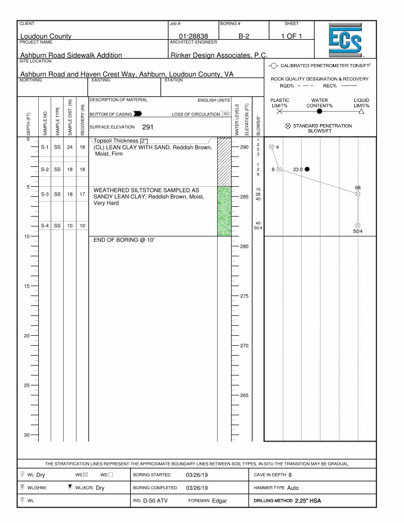
(CL) LEAN CLAY WITH SAND, Reddish Brown, Moist, Firm
WEATHERED SILTSTONE SAMPLED ASSANDY LEAN CLAY, Reddish Brown, Moist,Very Hard
END OF BORING @ 10'
1223
126
152840
4050/4
4
8 23.0
68
50/4
CLIENT
Loudoun County
Job #:
01:28838
BORING #
B-2
SHEET
PROJECT NAME
Ashburn Road Sidewalk Addition
ARCHITECT-ENGINEER
Rinker Design Associates, P.C.SITE LOCATION
Ashburn Road and Haven Crest Way, Ashburn, Loudoun County, VANORTHING EASTING STATION
THE STRATIFICATION LINES REPRESENT THE APPROXIMATE BOUNDARY LINES BETWEEN SOIL TYPES. IN-SITU THE TRANSITION MAY BE GRADUAL.
WL Dry WS WD BORING STARTED 03/26/19 CAVE IN DEPTH 8
WL(SHW) WL(ACR) Dry BORING COMPLETED 03/26/19 HAMMER TYPE Auto
WL RIG D-50 ATV FOREMAN Edgar DRILLING METHOD 2.25" HSADRILLING METHOD 2.25" HSA
DE
PT
H (
FT
)
SA
MP
LE
NO
.
SA
MP
LE
TY
PE
SA
MP
LE
DIS
T. (I
N)
RE
CO
VE
RY
(IN
)
SURFACE ELEVATION
DESCRIPTION OF MATERIAL
WA
TE
R L
EV
ELS
ELE
VA
TIO
N (
FT
)
BLO
WS
/6"
10 20 30 40 50+
20% 40% 60% 80% 100%
1 2 3 4 5+
ENGLISH UNITS
BOTTOM OF CASING LOSS OF CIRCULATION
CALIBRATED PENETROMETER TONS/FT2
PLASTICLIMIT %
WATERCONTENT %
LIQUIDLIMIT %
ROCK QUALITY DESIGNATION & RECOVERY
RQD% REC.%
STANDARD PENETRATIONBLOWS/FT291
1 OF 1

0
5
10
15
20
25
30
285
280
275
270
265
260
S-1
S-2S-2
S-3
SS
SS
SS
24
18
18
16
17
14
Topsoil Thickness [2"]
(CL) LEAN CLAY WITH SAND, Reddish Brown, Moist, Stiff
WEATHERED SILTSTONE SAMPLED ASCLAYEY SAND WITH GRAVEL, ReddishBrown, Moist, Very Dense
AUGER REFUSAL @ 7.1'
3355
34
10
72848
8
3020
19.614
76
CLIENT
Loudoun County
Job #:
01:28838
BORING #
B-3
SHEET
PROJECT NAME
Ashburn Road Sidewalk Addition
ARCHITECT-ENGINEER
Rinker Design Associates, P.C.SITE LOCATION
Ashburn Road and Haven Crest Way, Ashburn, Loudoun County, VANORTHING EASTING STATION
THE STRATIFICATION LINES REPRESENT THE APPROXIMATE BOUNDARY LINES BETWEEN SOIL TYPES. IN-SITU THE TRANSITION MAY BE GRADUAL.
WL Dry WS WD BORING STARTED 03/26/19 CAVE IN DEPTH 5
WL(SHW) WL(ACR) Dry BORING COMPLETED 03/26/19 HAMMER TYPE Auto
WL RIG D-50 ATV FOREMAN Edgar DRILLING METHOD 2.25" HSADRILLING METHOD 2.25" HSA
DE
PT
H (
FT
)
SA
MP
LE
NO
.
SA
MP
LE
TY
PE
SA
MP
LE
DIS
T. (I
N)
RE
CO
VE
RY
(IN
)
SURFACE ELEVATION
DESCRIPTION OF MATERIAL
WA
TE
R L
EV
ELS
ELE
VA
TIO
N (
FT
)
BLO
WS
/6"
10 20 30 40 50+
20% 40% 60% 80% 100%
1 2 3 4 5+
ENGLISH UNITS
BOTTOM OF CASING LOSS OF CIRCULATION
CALIBRATED PENETROMETER TONS/FT2
PLASTICLIMIT %
WATERCONTENT %
LIQUIDLIMIT %
ROCK QUALITY DESIGNATION & RECOVERY
RQD% REC.%
STANDARD PENETRATIONBLOWS/FT289
1 OF 1

0
5
10
15
20
25
30
290
285
280
275
270
265
S-1
S-2
S-3
S-4
SS
SS
SS
SS
24
18
18
10
8
11
17
10
Topsoil Thickness [2"]
(CL FILL) LEAN CLAY WITH GRAVEL, DarkBrown, Moist, Stiff
(CL) GRAVELLY LEAN CLAY WITH SAND,Reddish Brown, Moist, Stiff
WEATHERED SILTSTONE SAMPLED ASCLAYEY SAND WITH GRAVEL, ReddishBrown, Moist, Very Dense
END OF BORING @ 10'
1354
459
82436
1150/4
8
14 20.1
60
50/4
CLIENT
Loudoun County
Job #:
01:28838
BORING #
B-4
SHEET
PROJECT NAME
Ashburn Road Sidewalk Addition
ARCHITECT-ENGINEER
Rinker Design Associates, P.C.SITE LOCATION
Ashburn Road and Haven Crest Way, Ashburn, Loudoun County, VANORTHING EASTING STATION
THE STRATIFICATION LINES REPRESENT THE APPROXIMATE BOUNDARY LINES BETWEEN SOIL TYPES. IN-SITU THE TRANSITION MAY BE GRADUAL.
WL Dry WS WD BORING STARTED 03/26/19 CAVE IN DEPTH 7
WL(SHW) WL(ACR) Dry BORING COMPLETED 03/26/19 HAMMER TYPE Auto
WL RIG D-50 ATV FOREMAN Edgar DRILLING METHOD 2.25" HSADRILLING METHOD 2.25" HSA
DE
PT
H (
FT
)
SA
MP
LE
NO
.
SA
MP
LE
TY
PE
SA
MP
LE
DIS
T. (I
N)
RE
CO
VE
RY
(IN
)
SURFACE ELEVATION
DESCRIPTION OF MATERIAL
WA
TE
R L
EV
ELS
ELE
VA
TIO
N (
FT
)
BLO
WS
/6"
10 20 30 40 50+
20% 40% 60% 80% 100%
1 2 3 4 5+
ENGLISH UNITS
BOTTOM OF CASING LOSS OF CIRCULATION
CALIBRATED PENETROMETER TONS/FT2
PLASTICLIMIT %
WATERCONTENT %
LIQUIDLIMIT %
ROCK QUALITY DESIGNATION & RECOVERY
RQD% REC.%
STANDARD PENETRATIONBLOWS/FT293
1 OF 1
0
5
10
15
20
25
30
35
280
275
270
265
260
255
250
(CL FILL) LEAN CLAY WITH GRAVEL, Dark Brown, Moist
(CL) LEAN CLAY WITH SAND, Reddish Brown, Moist
(SC) CLAYEY SAND WITH GRAVEL, Reddish Brown, Moist
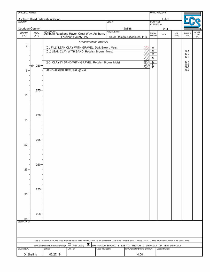
HAND AUGER REFUSAL @ 4.6'
MMM
M
DDD
S-1S-2S-3
S-4S-5S-6S-7
PROJECT NAME:
Ashburn Road Sidewalk Addition
HAND AUGER #
HA-1CLIENT:
Loudoun County
JOB #:
28838
SURFACE
ELEVATION
284LOCATION:Ashburn Road and Haven Crest Way, Ashburn,
Loudoun County, VA
ARCH./ENG:
Rinker Design Associates, P.C.
DESCRIPTION OF MATERIAL
REMARKS:
THE STRATIFICATION LINES REPRESENT THE APPROXIMATE BOUNDARY LINES BETWEEN SOIL TYPES. IN-SITU THE TRANSITION MAY BE GRADUAL.
GROUND WATER: While Drilling After Drilling EXCAVATION EFFORT: E - EASY M - MEDIUM D - DIFFICULT VD - VERY DIFFICULT
ECS REP.:
D. Sirstins
DATE:
03/27/19
UNITS: Cave-in Depth: Groundwater Before Drilling:
4.00
Groundwater:
DEPTH
(FT.)
ELEV.
(FT.)EXCAV.EFFORT
DCPQP
(TSF)SAMPLE
NO.
MOIST.CONT.
(%)

APPENDIX C – Laboratory Testing
Laboratory Test Results Summary Liquid and Plastic Limits Test Report Particle Size Distribution Report Electrical Resistivity Test Report

B-1
S-2 2.5 4.0 1.5 21.2
B-2
S-2 2.5 4.0 1.5 23.0
B-3
S-2 2.5 2.5 19.6 CL 30 20 10 76.3
B-4
S-2 2.5 4.0 1.5 20.1
HA-1 (1')
S-2 0.0 0.0 pH=7.35
HA-1 (2')
S-3 0.0 0.0 pH=6.74
Laboratory Testing Summary
Notes: 1. ASTM D 2216, 2. ASTM D 2487, 3. ASTM D 4318, 4. ASTM D 1140, 5. See test reports for test method, 6. See test reports for test method
Definitions: MC: Moisture Content, Soil Type: USCS (Unified Soil Classification System), LL: Liquid Limit, PL: Plastic Limit, PI: Plasticity Index, CBR: California Bearing Ratio, OC: Organic Content (ASTM D 2974)
Project No. 01:28838
Project Name: Ashburn Road Sidewalk Addition
PM: Sean D. Millar
PE: Nick Meloy
Printed On: Tuesday, April 9, 2019
SampleSource
SampleNumber
StartDepth(feet)
EndDepth(feet)
SampleDistance
(feet)
MC1
(%)Soil
Type2 LL
Atterberg Limits3
PL PI
PercentPassingNo. 200Sieve4
MaximumDensity
(pcf)
Moisture - Density (Corr.)5
OptimumMoisture
(%)
CBRValue6 Other
Page 1 of 1

Tested By: HNT1 Checked By: SDM
(CL) LEAN CLAY WITH SAND, brown 30 20 10 80.6 76.3 CL
28838 Loudoun County
MATERIAL DESCRIPTION LL PL PI %<#40 %<#200 USCS
Project No. Client: Remarks:
Project:
Figure
Source of Sample: B-3 Depth: 2.5-4 Sample Number: S-2
PL
AS
TIC
ITY
IN
DE
X
0
10
20
30
40
50
60
LIQUID LIMIT0 10 20 30 40 50 60 70 80 90 100 110
CL-ML
CL o
r OL
CH o
r OH
ML or OL MH or OH
Dashed line indicates the approximate
upper limit boundary for natural soils
4
7
LIQUID AND PLASTIC LIMITS TEST REPORT
Ashburn Road Sidewalk Addition

(no specification provided)*
PL= LL= PI=
USCS (D 2487)= AASHTO (M 145)=
D90= D85= D60=D50= D30= D15=D10= Cu= Cc=
Remarks
(CL) LEAN CLAY WITH SAND, brown
#4#10#40#60#80
#100#200
100.097.080.678.877.877.476.3
20 30 10
CL A-4(6)
1.0384 0.6898
4/1/19 4/2/19
HNT1
SDM
PM
Loudoun County
Ashburn Road Sidewalk Addition
28838
Material Description
Atterberg Limits (ASTM D 4318)
Classification
Coefficients
Date Received: Date Tested:
Tested By:
Checked By:
Title:
Date Sampled:Source of Sample: B-3 Depth: 2.5-4Sample Number: S-2
Client:
Project:
Project No: Figure
TEST RESULTS
Opening Percent Spec.* Pass?
Size Finer (Percent) (X=Fail)
PE
RC
EN
T F
INE
R
0
10
20
30
40
50
60
70
80
90
100
PE
RC
EN
T C
OA
RS
ER
100
90
80
70
60
50
40
30
20
10
0
GRAIN SIZE - mm.
0.0010.010.1110100
% +3"Coarse
% Gravel
Fine Coarse Medium
% Sand
Fine Silt
% Fines
Clay
0.0 0.0 0.0 3.0 16.4 4.3 76.3
6 in.
3 in.
2 in.
1½
in.
1 in.
¾ in.
½ in.
3/8
in.
#4
#10
#20
#30
#40
#60
#100
#140
#200
Particle Size Distribution Report
124751 ASTM G57 Measurement of Soil Resistivity
Measurement of Soil Resistivity Using the Two-Electrode
Soil Box Method
ASTM G57Project No.: 28838 Project Engineer: SDM/NCM
Project Name: Ashburn Road
Sample Location: HA-1
Sample Discription: Lean CLAY with Sand (CL)
Date Reveived: 4/1/2019 Date Tested 4/2/2019 Technician KV
Soil Box Dimensions:
Length = 10.922 cm Cross-sectional Area = 7.334814 cm2
Width = 2.978 cm Distance between electrodes = 6.81 cm
Height = 2.463 cm Soil Box Factor, SBF = 1.077065198 cm
Depth of Date Date ∆∆∆∆ Voltage ∆∆∆∆ Current Resistance Resistivity, ρρρρ
Sample No. Sample (Ft) Sampled Tested (Volts) (Amps) (Ohms) (Ohm-cm)
HA-1, S-2 1.0 ft _ 4/2/2019 2.844 0.00022 12927.3 13924
HA-1, S-3 2.0 ft _ 4/2/2019 2.666 0.00032 8331.3 8973
Notes

Appendix D – Supplemental Report Documents
French Drain Installation Procedure
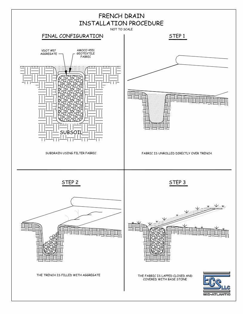
SUBSOIL
FINAL CONFIGURATION STEP 1
STEP 2 STEP 3
FRENCH DRAIN
INSTALLATION PROCEDURE
VDOT #57
AGGREGATE
AMOCO 4551
GEOTEXTILE
FABRIC
SUBDRAIN USING FILTER FABRIC FABRIC IS UNROLLED DIRECTLY OVER TRENCH
THE TRENCH IS FILLED WITH AGGREGATE THE FABRIC IS LAPPED CLOSED AND
COVERED WITH BASE STONE
NOT TO SCALE