edexcel physics a-level - pmt · 2020-01-31 · edexcel physics a-level topic 5: waves and particle...
TRANSCRIPT

Edexcel Physics A-levelTopic 5: Waves and Particle Nature of Light
Key Points
www.pmt.education
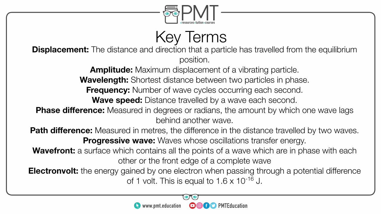
Key TermsDisplacement: The distance and direction that a particle has travelled from the equilibrium
position.Amplitude: Maximum displacement of a vibrating particle.
Wavelength: Shortest distance between two particles in phase.Frequency: Number of wave cycles occurring each second.
Wave speed: Distance travelled by a wave each second.Phase difference: Measured in degrees or radians, the amount by which one wave lags
behind another wave.Path difference: Measured in metres, the difference in the distance travelled by two waves.
Progressive wave: Waves whose oscillations transfer energy.Wavefront: a surface which contains all the points of a wave which are in phase with each
other or the front edge of a complete waveElectronvolt: the energy gained by one electron when passing through a potential difference
of 1 volt. This is equal to 1.6 x 10⁻¹⁶ J.
www.pmt.education

Longitudinal and Transverse WavesTransverse: Waves whose oscillations are perpendicular to the direction
of propagation of energy e.g. electromagnetic waves
Longitudinal: Waves whose oscillations are parallel to the direction of propagation of energy. They consist of compressions and rarefactions
e.g. sound waves
Only transverse waves can be polarised, which is where all the waves are oscillate in the same plane.
The discovery of polarised light helped prove that light was a transverse wave.
Polarisation can be used in things such as polaroid sunglasses to reduce glare or in a camera to enhance
the image.
TV and radio signals are polarised by the direction of the rods on the transmitting aerial. To receive these
signals well, you must ensure the receiving aerial and the waves are in the same plane.
Glare and CamerasRadio Signals
www.pmt.education

Speed of a waveThe speed of a wave is equal to the product of its frequency and wavelength. For an EM
wave this value is always equal to c, the speed of light in a vacuum. This can be expressed as the following equation:
v = fλIn order to calculate the speed of a transverse wave on a string you can use the
following equation:
v =√ Tμ
Where…T = tension on the string
μ = mass per unit length of the string
www.pmt.education

Superposition and InterferenceSuperposition is where the displacements of two waves are combined as they pass each
other. The total displacement at a point is equal to the sum of the individual displacements at that point. You should know that waves:
● Constructively interfere where they are in phase with each other ● Destructively interfere where they are in antiphase with each other (180 degrees out
of phase).
This can be explained in terms of peaks and troughs. When the waves are in phase, two peaks or two troughs will constructively interfere with each other, resulting in a ‘double’ peak or trough being created. When waves are in antiphase, a peak will meet a trough and result in destructive interference, which is where they cancel each other out and
produce a minimum point.
www.pmt.education

Stationary WavesA stationary wave is one that stores energy instead of transferring it from one point to another. You need to know the process of a stationary wave being formed on a string that
is fixed at both ends:
1. A wave is generated at one end of the string and travels down it2. At the other end , this wave is reflected and travels back in the opposite direction
3. The frequency of wave generation and the length of the string are such that the next wave generated meets this reflected wave and undergoes superposition
4. At places where the two waves are in phase, they undergo constructive interference and form a maximum point known as an antinode
5. At places where the two waves are in antiphase, they undergo destructive interference and form a minimum point known as an node
www.pmt.education
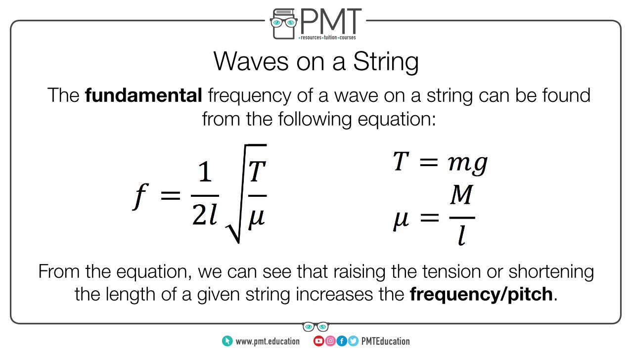
Waves on a StringThe fundamental frequency of a wave on a string can be found
from the following equation:
From the equation, we can see that raising the tension or shortening the length of a given string increases the frequency/pitch.
www.pmt.education

DiffractionDiffraction is the spreading out of waves when they pass through a gap or over an edge.
Diffraction depends on the gap width and the wavelength of the wave. If the gap is: ● A lot bigger than the wavelength, the diffraction is unnoticeable
● A bit wider than the wavelength, the diffraction is noticeable ● The same size as the wavelength, the diffraction is most noticeable
● Smaller than the wavelength, most of the waves are reflected
Huygen’s principle states that every point on a wavefront is a point source to secondary wavelets, which spread out to form the next wavefront. Huygen’s construction, which is based on this principle,
can be used to show what happens when a wave meets an obstacle and experiences diffraction, as shown below:
Image source: Arne Nordmann (norro), CC BY-SA 3.0
www.pmt.education

Diffraction grating
Diffraction is purely a wave property. Diffraction grating experiments show that light can experience diffraction, providing evidence for the wave nature of light.
Diffraction can be demonstrated by shining light through a diffraction grating. You can use the following equation when using a diffraction grating:
nλ = d sinθ
Depending on the type of light passed through a diffraction grating, the diffraction pattern will vary. Monochromatic light will form a pattern of alternating light and dark fringes, while white
light will form a white central fringe and alternating bright fringes which are spectra.
Intensity (I) is a measure of the power delivered per unit area.
PA
I =
www.pmt.education
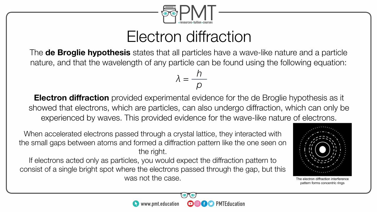
Electron diffractionThe de Broglie hypothesis states that all particles have a wave-like nature and a particle nature, and that the wavelength of any particle can be found using the following equation:
λ = h p
Electron diffraction provided experimental evidence for the de Broglie hypothesis as it showed that electrons, which are particles, can also undergo diffraction, which can only be
experienced by waves. This provided evidence for the wave-like nature of electrons.
When accelerated electrons passed through a crystal lattice, they interacted with the small gaps between atoms and formed a diffraction pattern like the one seen on
the right.If electrons acted only as particles, you would expect the diffraction pattern to
consist of a single bright spot where the electrons passed through the gap, but this was not the case.
www.pmt.education
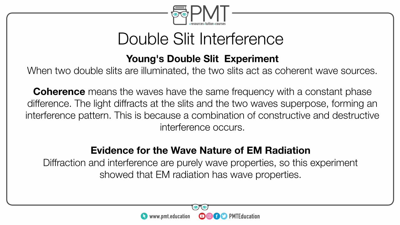
Double Slit InterferenceYoung's Double Slit Experiment
When two double slits are illuminated, the two slits act as coherent wave sources.
Coherence means the waves have the same frequency with a constant phase difference. The light diffracts at the slits and the two waves superpose, forming an interference pattern. This is because a combination of constructive and destructive
interference occurs.
Diffraction and interference are purely wave properties, so this experiment showed that EM radiation has wave properties.
Evidence for the Wave Nature of EM Radiation
www.pmt.education

RefractionRefraction is when a wave changes speed when it crosses into a new medium:
● If the medium is more optically dense, the wave will slow down and bend towards the normal
θᵢ > θᵣ● If the medium is less optically dense, the wave will speed up and bend away from the
normalθᵢ < θᵣ
A measure of how optically dense a medium is, is the material’s refractive index:
The absolute refractive index of a material measures
how much it slows down light. It is a ratio.
The relative refractive index at the boundary between two
materials is a ratio of the speed of light in the two materials.
n = cv ₁n₂ = c₁
c₂
www.pmt.education
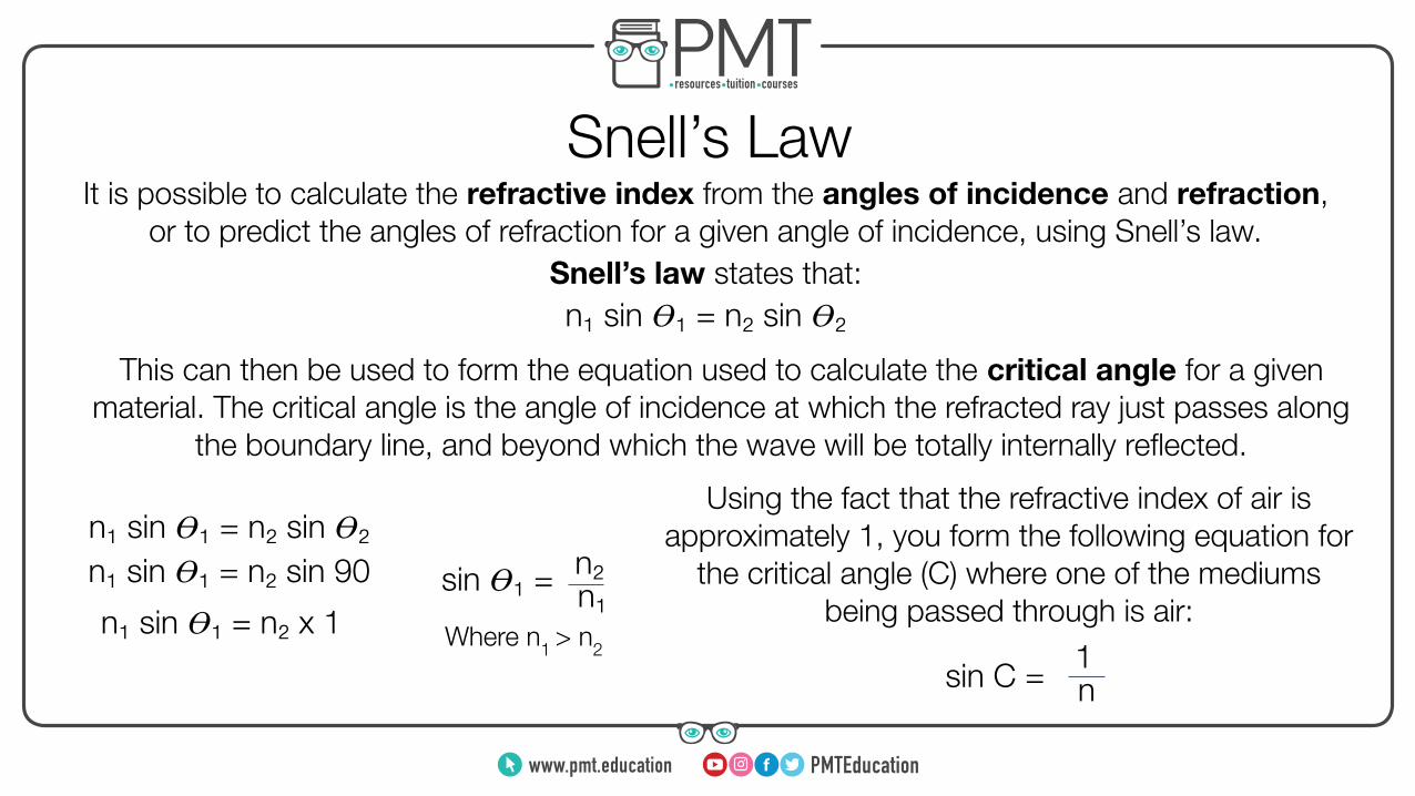
Snell’s LawIt is possible to calculate the refractive index from the angles of incidence and refraction,
or to predict the angles of refraction for a given angle of incidence, using Snell’s law.
n₁ sin 𝛳₁ = n₂ sin 𝛳₂ Snell’s law states that:
This can then be used to form the equation used to calculate the critical angle for a given material. The critical angle is the angle of incidence at which the refracted ray just passes along
the boundary line, and beyond which the wave will be totally internally reflected.
n₁ sin 𝛳₁ = n₂ sin 𝛳₂
n₁n₂n₁ sin 𝛳₁ = n₂ sin 90
n₁ sin 𝛳₁ = n₂ x 1 sin 𝛳₁ =
Using the fact that the refractive index of air is approximately 1, you form the following equation for
the critical angle (C) where one of the mediums being passed through is air:
Where n1 > n2
n1sin C =
www.pmt.education

Lenses
The focal length (f) of a lense is the distance from the centre of the lense to the focal point.
Power of a Lens:
1. A real image is one in which the rays of light actually converge to produce an image that can be projected onto a screen
2. A virtual image is one in which the rays of light only appear to have converged. Virtual images cannot be projected onto a screen
Lenses can produce two different kinds of image:
The focal point (F) of a lens is the point at which the rays of light converge, or appear to converge.
P = 1f
www.pmt.education
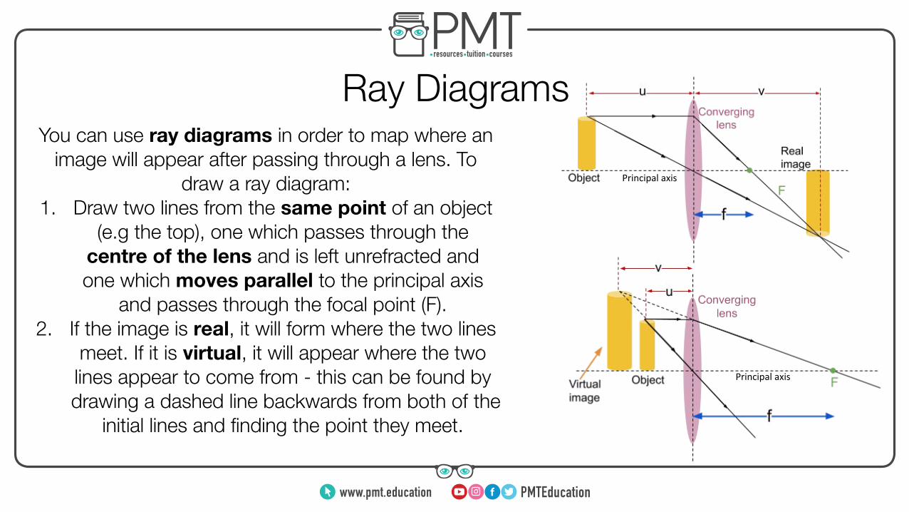
Ray DiagramsYou can use ray diagrams in order to map where an
image will appear after passing through a lens. To draw a ray diagram:
1. Draw two lines from the same point of an object (e.g the top), one which passes through the
centre of the lens and is left unrefracted and one which moves parallel to the principal axis
and passes through the focal point (F).2. If the image is real, it will form where the two lines
meet. If it is virtual, it will appear where the two lines appear to come from - this can be found by drawing a dashed line backwards from both of the
initial lines and finding the point they meet.
Principal axis
Principal axis
www.pmt.education
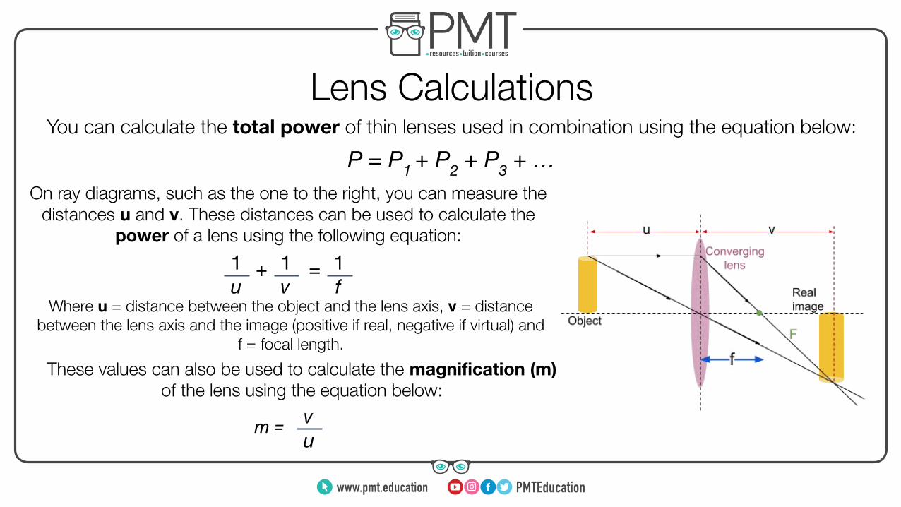
Lens CalculationsYou can calculate the total power of thin lenses used in combination using the equation below:
P = P1 + P2 + P3 + …On ray diagrams, such as the one to the right, you can measure the
distances u and v. These distances can be used to calculate the power of a lens using the following equation:
1 u
1 v
1 f
+ =
Where u = distance between the object and the lens axis, v = distance between the lens axis and the image (positive if real, negative if virtual) and
f = focal length.
These values can also be used to calculate the magnification (m) of the lens using the equation below:
m = v u
www.pmt.education

The Photoelectric EffectThe photoelectric effect is a phenomenon that demonstrates the particle-like nature of light.
The observations that are made are: ● If light of a high enough energy is shone on a metal surface, electrons are emitted
● If the frequency of the light is below the threshold frequency, no electrons will be emitted, regardless of the intensity of light
● If the intensity of light is increased, the rate of electron emission increases● The electrons are emitted with a range of kinetic energies
These observations led to the following conclusions:● Light exists in discrete packets of energy known as photons, which have an energy directly
proportional to their frequency. This is described by the equation below:
E = hf ● Each photon transfers all of its energy to a single electron - this is known as a one-to-one
interaction● If the energy of the photon is higher than the work function of the metal, the electron will be emitted
www.pmt.education
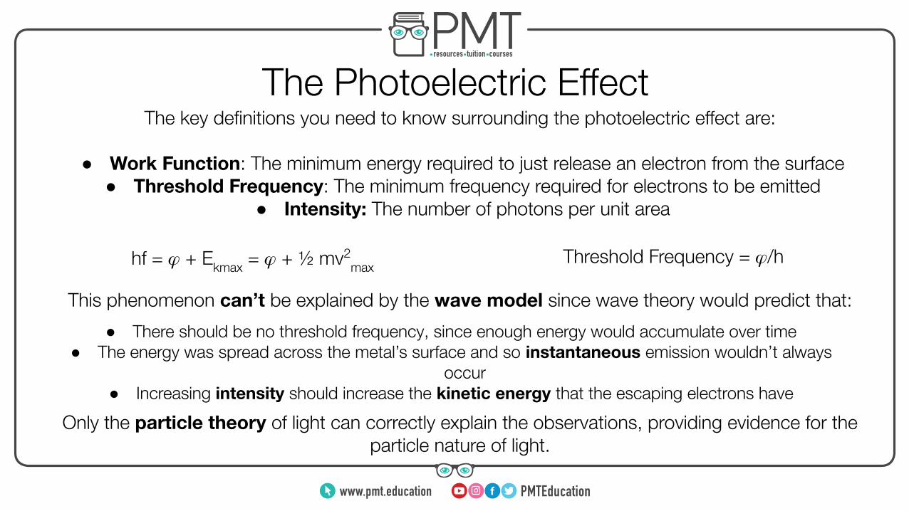
The Photoelectric EffectThe key definitions you need to know surrounding the photoelectric effect are:
This phenomenon can’t be explained by the wave model since wave theory would predict that:
● Work Function: The minimum energy required to just release an electron from the surface ● Threshold Frequency: The minimum frequency required for electrons to be emitted
● Intensity: The number of photons per unit area
● There should be no threshold frequency, since enough energy would accumulate over time● The energy was spread across the metal’s surface and so instantaneous emission wouldn’t always
occur● Increasing intensity should increase the kinetic energy that the escaping electrons have
Only the particle theory of light can correctly explain the observations, providing evidence for the particle nature of light.
hf = 𝜑 + Ekmax = 𝜑 + ½ mv2max
Threshold Frequency = 𝜑/h
www.pmt.education
Electron Energy LevelsElectrons only exist in discrete energy levels.
Ionisation is when an electron is removed from an atom. Excitation is the movement of electrons up to a higher energy level; either an electron collides with the orbital electron or a photon is absorbed by it, transferring energy to it. When the electron
de-excites, it moves down in energy levels and emits a photon.
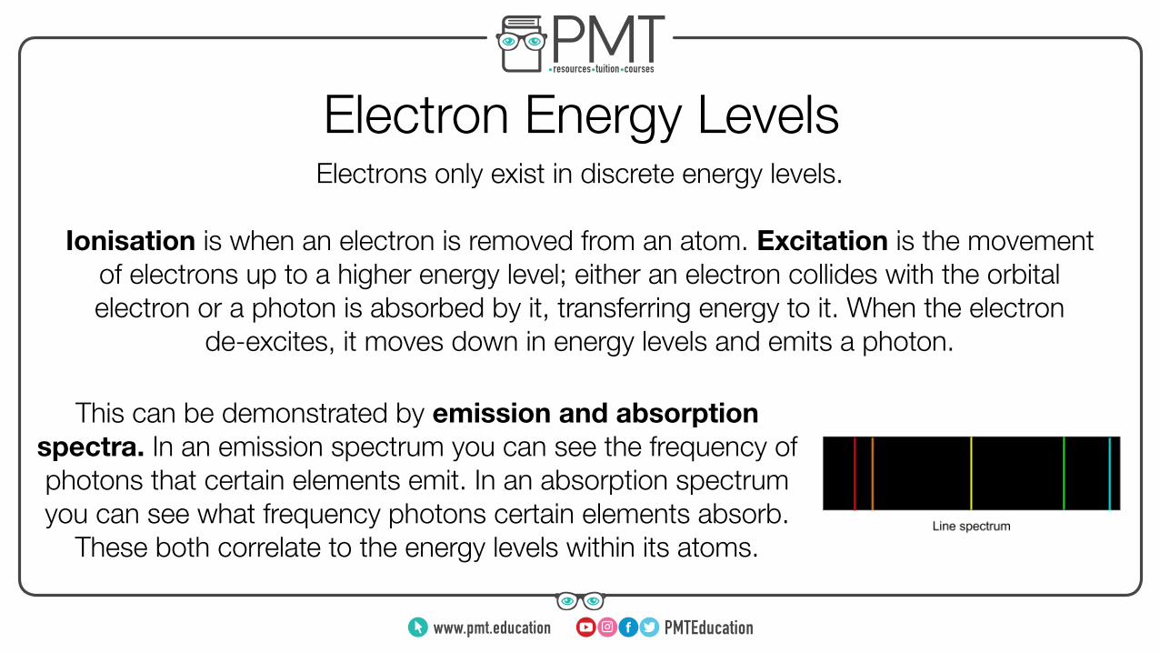
This can be demonstrated by emission and absorption spectra. In an emission spectrum you can see the frequency of photons that certain elements emit. In an absorption spectrum you can see what frequency photons certain elements absorb.
These both correlate to the energy levels within its atoms.
www.pmt.education
Pulse-Echo TechniqueThe pulse-echo technique is used with ultrasound waves (sounds waves with a frequency greater
than 20 kHz) for the imagining of objects, notably for medical imaging.
Below is a brief description the pulse-echo technique:1. Short pulse ultrasound waves are transmitted into the target (e.g the body in medical imaging).
2. As the waves move through the target, they will meet boundaries of different densities, therefore they will be reflected. The amount of reflection depends on the difference in densities of the
materials; the greater this difference, the greater the reflection.3. The reflected waves are detected as they leave the target.
4. The intensities of the reflected waves will determine the structure of the target and the time taken for these reflected waves to return will determine the position of objects in the target (using s = vt).
The resolution of the image can be increased by:● Decreasing the wavelength of the waves used
● Decreasing the duration of the pulses of waves, as this will decrease the likelihood that the waves will overlap
www.pmt.education