edinburgh research exploreradequate anchorage at the edge of the slab. ribbed reinforcing bars were...
TRANSCRIPT
Edinburgh Research Explorer
Punching Shear of Restrained Reinforced Concrete Slabs UnderFire Conditions
Citation for published version:Smith, HKM, Stratford, T & Bisby, L 2014, Punching Shear of Restrained Reinforced Concrete Slabs UnderFire Conditions. in 8th International Conference on Structures in Fire. vol. 1, Tongji University Press,Shanghai, pp. 443-450.
Link:Link to publication record in Edinburgh Research Explorer
Document Version:Peer reviewed version
Published In:8th International Conference on Structures in Fire
General rightsCopyright for the publications made accessible via the Edinburgh Research Explorer is retained by the author(s)and / or other copyright owners and it is a condition of accessing these publications that users recognise andabide by the legal requirements associated with these rights.
Take down policyThe University of Edinburgh has made every reasonable effort to ensure that Edinburgh Research Explorercontent complies with UK legislation. If you believe that the public display of this file breaches copyright pleasecontact [email protected] providing details, and we will remove access to the work immediately andinvestigate your claim.
Download date: 17. May. 2020

8th International Conference on Structures in Fire Shanghai, China, June 11-13, 2014
PUNCHING SHEAR OF RESTRAINED REINFORCED CONCRETE SLABS UNDER FIRE CONDITIONS
Holly K.M. Smith, Tim J. Stratford and Luke A. Bisby
School of Engineering, The University of Edinburgh, Edinburgh, EH9 3JL, United Kingdom e-mails: [email protected], [email protected], [email protected]
Keywords: Punching Shear, Fire, Reinforced-concrete, Slabs, Experiments.
Abstract. The punching shear resistance of reinforced concrete slabs involves material property degradation and the effects of restrained thermal expansion in both the slabs and columns, in addition to the complexities of shear mechanisms in concrete. This paper examines how the restraint of thermal expansion in the slab affects its punching shear capacity in fire. It presents a series of tests on fifteen slabs under a combination of applied load and fire, using a purpose-built restraint frame that allowed the boundary restraint actions to be controlled and monitored. The test results demonstrate that unrestrained slabs can fail very soon after the start of heating, whereas the equivalent restrained slabs survive up to two hours of heating. One of the restrained slabs failed in cooling, possibly due to tensile actions that developed due to the restraint conditions.
1 INTRODUCTION
The shear behaviour of concrete in fire is poorly understood compared to its flexural response, and the Gretzenbach car park failure in Switzerland in 2004 prompted concerns over our lack of understanding of the punching shear response of concrete in fire. Shear in concrete at elevated temperature is dependent upon the effects of temperature on the steel and concrete properties with temperature and differential thermal expansion effects, combined with the complexities of shear behaviour of concrete at ambient temperature which in itself remains the subject of research in its own right.
There have been relatively few investigations of punching shear in fire. Tests have been conducted by Kordina [1], Annerel et al. [2], Salem et al. [3] and Ghoreishi et al. [4], and these have been accompanied by thermo-mechanical models by Annerel et al. [5] and Bamonte et al. [6]. A summary of prior work can be found in Ghoreishi et al. [4].
The shear capacity of concrete at ambient temperature is known to be affected by the presence of in-plane membrane forces [e.g.7]; punching shear capacity is improved by in-plane compression. During fire, membrane forces result from restrained thermal actions, and the above prior work has identified that premature punching shear failure could consequently result from restrained thermal action. There has not, however, been an experimental investigation into the effect of restraint conditions upon the punching shear response of a concrete slab in fire, and these effects are not included in current code provisions. This paper presents an experimental study in which the effects of restrained thermal action upon punching shear in fire were investigated.
2 EXPERIMENTAL PROGRAMME
2.1 Test Configuration This paper reports an experimental investigation of the punching shear performance of
1400×1400mm flat concrete slabs during fire. The tests were conducted in a purpose-built reaction frame

Holly K.M. Smith, Tim J. Stratford and Luke A. Bisby
that allowed investigation of the in-plane restraint upon the heated punching shear behaviour. The boundary support conditions are shown schematically in Figure 1: the concrete slabs were either restrained (fixed against in-plane expansion and edge moment), or unrestrained (allowed to expand, and free to rotate).
The test arrangement is shown in Figure 2, although much of the detail is hidden within the restraint frame that supported the four sides of the test slabs. The slabs were heated from above using a 960×990 mm array of propane gas radiant panels (enclosed within ceramic board used to insulate the test frame). Heating from above avoids possible damage to the radiant panels during failure of the concrete slab, but means that the tests were inverted, and consequently this must be borne in mind when interpreting the test results that follow.
Load was applied to a column stub cast into the centre of each slab specimens by means of a thermally-insulated pull rod and actuator placed beneath the slab.
Figure 1. Schematic of test setup (showing fully restrained support arrangement on left; unrestrained support on right).
Figure 2. Heated test setup overview.
2.2 Instrumentation Temperatures were recorded using fifteen thermocouples within each heated slab, with five
thermocouples distributed through the depth of the slab at each of three positions, each placed 150 mm outside the expected punching shear perimeter of the slab.
Fire
Load
UnrestrainedRestrained
Radiant panels
Restraint frame
Slab position
Load actuator
DIC cameras
Holly K.M. Smith, Tim J. Stratford and Luke A. Bisby
The vertical deflection at the centre of the slab was measured using displacement transducers. In addition, digital image correlation (DIC) was used to record the slab deflection across the whole of the unheated (lower) surface. Three cameras were positioned beneath the slab (Figure 2), and a bespoke 3D algorithm (based upon the GeoPIV image correlation code [8]) was used to determine deflections from the recorded images. It has previously been demonstrated that this is an effective method of recording displacement at high temperatures without the inherent difficulties of traditional contact measurement methods [9].
As well as recording the vertical load applied to centre of the slab, the in-plane reaction force and moment (shown in Figure 1) were recorded on each of the four sides of the slab by means of strain gauges bonded to the reaction frame.
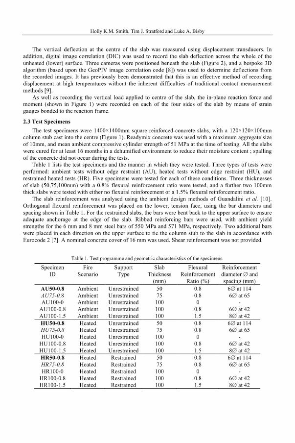
2.3 Test Specimens The test specimens were 1400×1400mm square reinforced-concrete slabs, with a 120×120×100mm
column stub cast into the centre (Figure 1). Readymix concrete was used with a maximum aggregate size of 10mm, and mean ambient compressive cylinder strength of 51 MPa at the time of testing. All the slabs were cured for at least 16 months in a dehumified environment to reduce their moisture content ; spalling of the concrete did not occur during the tests.
Table 1 lists the test specimens and the manner in which they were tested. Three types of tests were performed: ambient tests without edge restraint (AU), heated tests without edge restraint (HU), and restrained heated tests (HR). Five specimens were tested for each of these conditions. Three thicknesses of slab (50,75,100mm) with a 0.8% flexural reinforcement ratio were tested, and a further two 100mm thick slabs were tested with either no flexural reinforcement or a 1.5% flexural reinforcement ratio.
The slab reinforcement was analysed using the ambient design methods of Guandalini et al. [10]. Orthogonal flexural reinforcement was placed on the lower, tension face, using the bar diameters and spacing shown in Table 1. For the restrained slabs, the bars were bent back to the upper surface to ensure adequate anchorage at the edge of the slab. Ribbed reinforcing bars were used, with ambient yield strengths for the 6 mm and 8 mm steel bars of 550 MPa and 571 MPa, respectively. Two additional bars were placed in each direction on the upper surface to tie the column stub to the slab in accordance with Eurocode 2 [7]. A nominal concrete cover of 16 mm was used. Shear reinforcement was not provided.
Table 1. Test programme and geometric characteristics of the specimens.
Specimen ID
Fire Scenario
Support Type
Slab Thickness
(mm)
Flexural Reinforcement
Ratio (%)
Reinforcement diameter ∅ and spacing (mm)
AU50-0.8 Ambient Unrestrained 50 0.8 6∅ at 114 AU75-0.8 Ambient Unrestrained 75 0.8 6∅ at 65 AU100-0 Ambient Unrestrained 100 0 -
AU100-0.8 Ambient Unrestrained 100 0.8 6∅ at 42 AU100-1.5 Ambient Unrestrained 100 1.5 8∅ at 42 HU50-0.8 Heated Unrestrained 50 0.8 6∅ at 114 HU75-0.8 Heated Unrestrained 75 0.8 6∅ at 65 HU100-0 Heated Unrestrained 100 0 -
HU100-0.8 Heated Unrestrained 100 0.8 6∅ at 42 HU100-1.5 Heated Unrestrained 100 1.5 8∅ at 42 HR50-0.8 Heated Restrained 50 0.8 6∅ at 114 HR75-0.8 Heated Restrained 75 0.8 6∅ at 65 HR100-0 Heated Restrained 100 0 -
HR100-0.8 Heated Restrained 100 0.8 6∅ at 42 HR100-1.5 Heated Restrained 100 1.5 8∅ at 42
Holly K.M. Smith, Tim J. Stratford and Luke A. Bisby
2.4 Test Sequence The ambient tests were conducted using a displacement rate of 2 mm/min to determine their ultimate
capacity. These ambient tests results were first used to calibrate a capacity model using Guandalini et al.’s method [10] (recognising the inherent variability of the small number of ambient test results). This model was used to calculate the sustained load to be applied during the heated tests, which was taken to be 70% of the ambient capacity (in accordance with Eurocode 1-2 [11] and similar to other tests [1]). Note that the same load was applied to both the restrained and unrestrained slabs, because the punching shear capacity is not influenced by the edge restraint according to ambient design methods.
The heated slabs were loaded at a displacement rate of 2 mm/min until the required load had been reached. This load was then held constant, whilst the slabs were heated using the gas radiant panels. Heating ended either after two hours or when slab failure occurred. (Note that these tests did not attempt to follow a standard fire curve. The radiant panels applied a nominal heat flux at slab level of approximately 50 kW/m2, and the thermocouple data will be used to calculate the thermal load during future analysis of the tests).
For the slabs that did not fail after two hours of heating, the applied load was maintained whilst the slabs cooled until temperatures dropped below 150°C throughout their depth, and then the load was removed at a displacement rate of 2 mm/min. Residual strength tests were conducted the following day on these specimens.
2 EXPERIMENTAL RESULTS AND DISCUSSION
This paper presents key results from the test series in terms of load capacities, slab temperatures, and vertical deflections. Other results (such as the boundary restraint forces and further interpretation of the slab behaviour) will follow after additional analysis.
3.1 Overview of the Test Results Table 2 summarises the key test results. For the ambient tests, it records the failure load and
corresponding central displacement. For the heated tests, the table gives the sustained load that was applied during heating.
• The three unrestrained 100mm thick slabs (HU100-0, HU100-0.8, HU100-1.5) failed very soon after heating commenced; the recorded failure loads for these slabs are a little higher than the intended applied loads due to friction in the load application system.
• The most heavily reinforced of the restrained 100mm thick slabs (HR100-1.5) failed during cooling.
• The remaining heated slabs had not failed after 2 hours of heating. Table 2 gives the residual strengths for these slabs.
Note that gas supply limitations resulted in test HR100-0 being halted after 99 minutes of heating.
Furthermore (and as shown below) the gas supply and hence applied heat flux reduced for specimen HR100-1.5, and hence this specimen was heated for 105 minutes.
3.2 Failure Mechanisms and Crack Patterns Figure 3 shows cross-sections through four representative slabs after failure. HU50-0.8 and HU75-0.8
failed in flexure-shear mechanisms, whereas HR100-0.8 and HR100-1.5 failed in pure shear with the larger punching shear cone that is to be expected for the larger slab thickness. The combination of flexure-shear failure and lack of edge restraint means that the residual deflection of the 50 and 75mm thick slabs is far greater than the 100mm slabs, which failed in pure shear, and had rotational restraint at their edges.
A key result from these tests is that whilst all three of the 100 mm thick unrestrained specimens failed very soon after heating started (after 6, 11, or 14 mins of heating, see Table 2), none of the corresponding restrained specimens failed during heating. Restrained slab HR100-1.5, however, failed during cooling,

Holly K.M. Smith, Tim J. Stratford and Luke A. Bisby
and is likely to have been affected by the reduction in in-plane compression during cooling, which will be investigated further when the restraining force data is examined.
Table 2. Ambient and residual test results.
Specimen ID
Load Applied During Heating
(kN)
Failure Load (kN)
Residual Capacity
(kN)
Displacement at Failure Load
(mm)
Burn Time (min)
AU50-0.8 - 54.2 - 69.6 - AU75-0.8 - 101.4 - 31.8 - AU100-0 - 43.8 - 18.3 -
AU100-0.8 - 226.3 - 62.4 - AU100-1.5 - 279.7 - 38.7 - HU50-0.8 25.5 - 55.7 40.3 120 HU75-0.8 82.8 - 90.7 17.7 121 HU100-0 30.0 38.9 - 2.2 6
HU100-0.8 174.6 174.8 - 30.8 11 HU100-1.5 234.0 237.0 - 28.5 14 HR50-0.8 26.4 - 64.4 29.4 121 HR75-0.8 82.0 - 115.5 20.0 120 HR100-0 33.1 - 82.2 28.2 99 *
HR100-0.8 166.5 - 245.1 20.7 120 HR100-1.5 232.7 233.2 - 21.2 105 **
* Test terminated prematurely (gas supply failure). ** Specimen failed during cooling phase.
Figure 3. Cross-sections of selected slabs showing the post-failure crack patterns.
a) HU50-0.8
b) HU75-0.8
c) HR100-0.8
d) HR100-1.5
Holly K.M. Smith, Tim J. Stratford and Luke A. Bisby
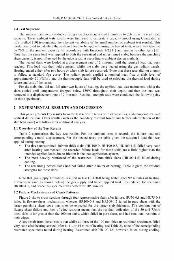
3.3 Temperature Evolution Figure 4 shows an example of the temperature profiles recording during the tests. Temperature
profiles are presented through the depth of slab HR100-1.5 at 10 minute intervals after ignition. Note that the heated surface is at the top of the plot due to the inverted test arrangement.
The maximum surface temperature reaches 484°C after 75 minutes of heating. As mentioned above, it was not possible to sustain the heat flux into the slab, and consequently the heated surface of the slab started to cool after 75 minutes, even though the radiant panels were still burning. The radiant panels were turned off after 105 minutes, and the slab was left to cool (shown by the dashed profiles). The temperatures on the unheated surface of the slab reached a maximum during the cooling phase (as the heat front penetrated the slab); for example the maximum temperature in the flexural steel (77mm from the heated surface) was 148°C, which occurred 145 mins after ignition, or 40 mins after cooling started.
Figure 4. Temperature profiles at 10 minute intervals for specimen HR100-1.5,
recorded using five thermocouples through the depth of the slab.
3.4 Vertical Displacements Figures 5 and 6 plot the vertical displacement versus time for all of the heated tests. Figure 5 shows
all of the slabs with 0.8% reinforcement ratio; Figure 6 shows all of the 100 mm thick slabs. Zero time corresponds to the start of heating, with the negative time region corresponding to loading
of the slabs prior to ignition. Positive deflection is downwards (i.e. in the direction of loading, away from the heat source, see Figure 1). The temperature of the flexural steel is also plotted for each test as a dashed line. In both plots, it can be seen that providing edge restraint significantly increases the stiffness of the slabs (as is to be expected).
Figure 6 demonstrates the influence of edge restraint condition upon punching shear capacity during a fire; the 100mm thick unrestrained slabs failed soon after the start of heating; whereas the restrained slabs withstood sustained heating without failure.
During heating it might be expected that the thermal gradient through the slabs (Figure 4) would cause thermal bowing in the opposite direction (towards the heat source), but this was not the case. In all cases, the deflection of the slabs increased in the direction of loading (away from the heat source),
0
10
20
30
40
50
60
70
80
90
100
0 50 100 150 200 250 300 350 400 450 500
Dep
th fr
om th
e he
ated
sur
face
(mm
)
Temperature (°C)
5 mins 75 mins105 mins185 mins

Holly K.M. Smith, Tim J. Stratford and Luke A. Bisby
indicating that the degradation in concrete properties and non-linear material behaviour dominates as it is heated.
Figure 5. Vertical displacement (solid lines) and steel temperatures (dashed lines) during tests on slabs with 0.8% reinforcement ratio.
Figure 6. Vertical displacement (solid lines) and steel temperatures (dashed lines)
during tests on 100mm thick slabs.
The sharp increase in deflection rate at the start of the cooling phase seen for each of the slabs is consistent with the heated surface cooling down, whilst the heat front propagates deeper into the slab (as observed during the cooling phase in Figure 4). As noted above, it was not possible to sustain the required heat flux during all of the tests, and consequently the surface temperature started to drop before the panels were turned off; this may explain why there is a less distinct change in the deflection rate for the 100mm
-50
50
150
250
350
450
0
10
20
30
40
50
60
70
-60 -30 0 30 60 90 120 150 180 210 240 270
Stee
l Tem
pera
ture
(°C
)
Ver
tical
Dis
plac
emen
t (m
m)
Time since ignition (min)
HU75
HR75
HU50
HR50
HU100
HR100
0
20
40
60
80
100
120
140
160
180
0
5
10
15
20
25
30
35
40
-60 -30 0 30 60 90 120 150 180 210 240 270
Stee
l Tem
pera
ture
(°C
)
Ver
tical
Dis
plac
emen
t (m
m)
Time since ignition (min)
HR1.5
HR0
HR0.8
HU0
HU1.5
HU0.8

Holly K.M. Smith, Tim J. Stratford and Luke A. Bisby
restrained slabs in Figure 6 (such as HR100-1.5). The authors are in the process of examining the deflected shape of the slabs obtained using DIC, together with the restraint forces recorded on the reaction frame. These are expected to give additional information on the vertical deflection response of the slabs.
5 CONCLUSION
This paper has presented a series of tests on model reinforced concrete slabs examining the effect of boundary restraint conditions upon punching shear capacity in fire. The slabs were restrained against in-plane expansion and edge rotation using a bespoke restraint frame that allowed tests to be conducted under either fully restrained or unrestrained conditions. A comprehensive set of temperature, deflection, and restraining actions were recorded during the tests.
The results demonstrate that the restraint conditions have a dramatic effect upon the punching shear capacity of flat slabs. The 100mm thick unrestrained slabs failed very soon after the start of heating, whereas the identical restrained slabs remained intact for up to 2 hours of heating, due to the development of in-plane compression due to restrained thermal expansion. The most heavily reinforced of the 100mm thick restrained slabs failed during cooling, potentially due to tension developing within the slab due to the edge restraint; however, interpretation of the test data has yet to be completed.
REFERENCES
[1] Kordina, K., “Über das Brandverhalten punktgestützter Stahlbetonplatten” (On the Fire Behaviour of Reinforced Concrete Flat Slabs), Deutscher Ausschuss für Stahlbeton (DAfStb), Berlin (Germany), Heft 479, 106 pp, 1997.
[2] Annerel, E., Lu, L., Taerwe, L. “Punching Shear Tests on Flat Concrete Slabs Exposed to Fire”. Fire Safety Journal, 57, 83-95., 2013.
[3] Salem H., Issa H., Gheith H., Farahet A. “Punching shear strength of reinforced concrete flat slabs subjected to fire on their tension sides”. HBRC Journal, 8(1), 36-46, 2012.
[4] Ghoreishi, M., Bagchi, A., & Sultan, M. A. “Review of the Punching Shear Behavior of Concrete Flat Slabs in Ambient and Elevated Temperature”. Journal of Structural Fire Engineering, 4, 259–279, 2013.
[5] Annerel, E., Taerwe, L., Merci, B., Jansen, D., Bamonte, P., Felicetti, R. “Thermo-Mechanical Analysis of an Underground Car Park Structure Exposed to Fire”. Fire Safety Journal, 57, 96-106, 2013.
[6] Bamonte, P., Fernández, M. R., Muttoni, A. “Punching Shear Strength of R/C Slabs Subjected to Fire”. 7th International Conference on Structures in Fire, Fontana, M., Frangi, A., Knobloch, M. (eds.) Zurich, Switzerland, June 6-8, 2012.
[7] Eurocode 2, Design of concrete structures, Part 1-1: General rules and rules for buildings, EN 1992-1-1, 2004.
[8] White D.J., Take W.A., Bolton M.D. “Soil deformation measurement using particle image velocimetry (PIV) and photogrammetry”. Geotechnique, 53(7): 619–631, 2003.
[9] Gales, J.A., Bisby, L., & Stratford, T. “New parameters to describe high-temperature deformation of prestressing steel determined using digital image correlation”. Structural Engineering International, 22(4), 476–486, 2012.
[10] Guandalini, S., Burdet, O., & Muttoni, A. “Punching tests of slabs with low reinforcement ratios”. ACI Structural Journal, 106(10), 87–95, 2009.
[11] Eurocode 2, Design of concrete structures, Part 1-2: General rules - Structural fire design, EN 1992-1-2, 2004.