edinburgh research · pdf filedesign, analysis, and characterization of stress-engineered 3d...
TRANSCRIPT
Edinburgh Research Explorer
Fabrication and characterisation of suspended microstructuresof tantalum
Citation for published version:Al-Masha-al, A, Cheung, R, Bunting, A & Mastropaolo, E 2016, 'Fabrication and characterisation ofsuspended microstructures of tantalum' Journal of Micromechanics and Microengineering. DOI:10.1088/0960-1317/27/1/015020
Digital Object Identifier (DOI):10.1088/0960-1317/27/1/015020
Link:Link to publication record in Edinburgh Research Explorer
Document Version:Publisher's PDF, also known as Version of record
Published In:Journal of Micromechanics and Microengineering
General rightsCopyright for the publications made accessible via the Edinburgh Research Explorer is retained by the author(s)and / or other copyright owners and it is a condition of accessing these publications that users recognise andabide by the legal requirements associated with these rights.
Take down policyThe University of Edinburgh has made every reasonable effort to ensure that Edinburgh Research Explorercontent complies with UK legislation. If you believe that the public display of this file breaches copyright pleasecontact [email protected] providing details, and we will remove access to the work immediately andinvestigate your claim.
Download date: 14. May. 2018

This content has been downloaded from IOPscience. Please scroll down to see the full text.
Download details:
IP Address: 129.215.240.223
This content was downloaded on 12/12/2016 at 15:05
Please note that terms and conditions apply.
Fabrication and characterisation of suspended microstructures of tantalum
View the table of contents for this issue, or go to the journal homepage for more
2017 J. Micromech. Microeng. 27 015020
(http://iopscience.iop.org/0960-1317/27/1/015020)
Home Search Collections Journals About Contact us My IOPscience
You may also be interested in:
Residual stress measurement method in MEMS microbeams by using frequency shift data
Aurelio Somà and Alberto Ballestra
Characterization of nanomechanical graphene drum structures
C-L Wong, M Annamalai, Z-Q Wang et al.
An equation-based nonlinear model for non-flat MEMS fixed–fixed beams with non-vertical anchoring
supports
Juan Zeng, Anurag Garg, Andrew Kovacs et al.
Design, analysis, and characterization of stress-engineered 3D microstructures comprised of PECVD
silicon oxide and nitride
Chia-Hsing Pi and Kevin T Turner
A wafer mapping technique for residual stress in surface micromachined films
G Schiavone, J Murray, S Smith et al.
Silicon dioxide sacrificial layer etching in surface micromachining
J Bühler, F-P Steiner and H Baltes
Stress in low-temperature plasma enhanced chemical vapour deposited silicon nitride thinfilms
M Martyniuk, J Antoszewski, C A Musca et al.
Buckling of polysilicon microbeams during sacrificial layer removal
Tong-Yi Zhang, Xin Zhang and Yitshak Zohar
Silicon dioxide films by RF sputtering for microelectronic and MEMS applications
Vivekanand Bhatt and Sudhir Chandra
1 © 2016 IOP Publishing Ltd Printed in the UK
1. Introduction
Microelectromechanical systems (MEMS) based devices such as membranes and beams have been used extensively in different application areas including pressure sensors [1–3], electrostatic actuators [4], and RF switches [5, 6]. One of the most important MEMS devices that have attracted much interest in sensing application is a resonant gate transistor (RGT) [7]. These devices consist of source/drain regions and metal beam that could be vibrated within the desired tuning range of frequency for audio applications [8]. From the design and performance points-of-view, doubly sup-ported (or fixed–fixed) beams are possible structures for
dynamic tuning of actuators and sensors in resonant MEMS devices [9]. Tantalum can be used as a structural metal beam because of its promising physical and chemical prop-erties such as wear resistance, high melting point, and low ratio of Young’s modulus to mass density [8, 10]. However, residual stress in the metal beam is a problematic issue and can influence the performance and stability of the final fabricated device. For instance, the dynamic response of tantalum bridge-like structures has been found to be influ-enced greatly by the residual stress in tantalum film [8, 10]. The formation of suspended mems devices faces stress-related problems during film deposition and post-fabrication processes. During the film deposition, there are two main
Journal of Micromechanics and Microengineering
Fabrication and characterisation of suspended microstructures of tantalum
A Al-masha’al1, E Mastropaolo, A Bunting, C Dunare and R Cheung
Scottish Microelectronics Centre, Institute for Integrated Micro and Nano Systems, School of Engineering, The University of Edinburgh, Edinburgh EH9 3FF, UK
E-mail: [email protected] and [email protected]
Received 5 July 2016, revised 16 August 2016Accepted for publication 2 September 2016Published 16 November 2016
AbstractAn investigation of the influence of deposition and post-fabrication processes on the final mechanical structure of tantalum beams is reported in the present study. The final deflection profiles of doubly supported beams made from compressive and tensile-stressed films have been studied experimentally. An optimum finite element model has been developed to predict the buckling behaviour of the doubly supported beams by considering the boundary conditions in the form of a compressive stress and an applied load. No matter which etch release method has been used, the initial stress state of the as-deposited films has been found to have a significant impact on the final deflection profile of the fabricated device. The compressive-stressed films have presented larger deflection in the final released beams than the tensile-stressed films. Taking into account the type of etch release methods, the beams that have been released in the dry etch release processes have been found to deform more vertically than those released in the wet-etch release method. Moreover, it has been found that the amplitude of vertical deflection increases with the increase of the beam length and thickness. The results indicate that optimum profiles of tantalum suspended structures can be obtained from the tensile-stressed films that have been released by the wet etching method with an aspect ratio of 1:48.
Keywords: residual stress, buckling, dry etching, wet etching, tantalum
(Some figures may appear in colour only in the online journal)
A Al-masha’al et al
Printed in the UK
015020
JMMIEZ
© 2016 IOP Publishing Ltd
27
J. Micromech. Microeng.
JMM
0960-1317
10.1088/0960-1317/27/1/015020
Paper
1
Journal of Micromechanics and Microengineering
IOP
Original content from this work may be used under the terms of the Creative Commons Attribution 3.0 licence. Any further
distribution of this work must maintain attribution to the author(s) and the title of the work, journal citation and DOI.
1 Author to whom any Correspondence should be addressed.Institute for Integrated Micro and Nano Systems, School of Engineering, The University of Edinburgh, Edinburgh EH9 3FF, UK
2017
0960-1317/17/015020+9$33.00
doi:10.1088/0960-1317/27/1/015020J. Micromech. Microeng. 27 (2017) 015020 (9pp)

A Al-masha’al et al
2
components of the residual stress; intrinsic stress and extrinsic stress. The residual intrinsic stresses include growth stress that evolves as a consequence of the film nucleation during the deposition process and transformation stress that arises during a phase transformation and misfit stress that results from film-substrate lattice mismatch. The residual extrinsic stress develops as a thermal stress that arises from the mismatch of film-substrate thermal expansion coefficients. During the post-fabrication process, however, processing parameters may impose external stress in the form of an applied force on the fabricated device [11]. Cracking, deflection and buckling in the released microstructures are undesirable consequences of the residual stress and other post-processing effects.
In order to obtain robust and reliable devices, the mechan-ical properties of structural metal beam should be improved by controlling the residual stress and etch release effects during the fabrication process. Although there has been plenty of research on analysing or controlling the residual stress in various types of materials [10, 12–24], the behaviour of compressive or tensile-stressed films under different etch release conditions have not yet been addressed in the litera-ture. Moreover, the deflection behaviour of structural metal materials such as tantalum has not been studied satisfactorily as much as the semiconductor processing materials such as Si, SiO2 and Poly-Si. The present study offers an investigation of the influence of post-fabrication process on the final mechan-ical structure of suspended tantalum beams. Compressive and tensile-stressed films have been sputtered on two types of sacrificial layers. Both wet and dry etching techniques have been examined for the release of the final device in the form of doubly supported beams with length ranging from 100 to 400 µm. The final deflection profiles of the fabricated beams have been verified by creating several finite element models and analysing each model in terms of the compressive residual stress and external applied load. Further investigation has been performed to examine the influence of beam geometry, length, width and thickness, on the final deflection profile of the fabricated and simulated structures.
2. Experimental details
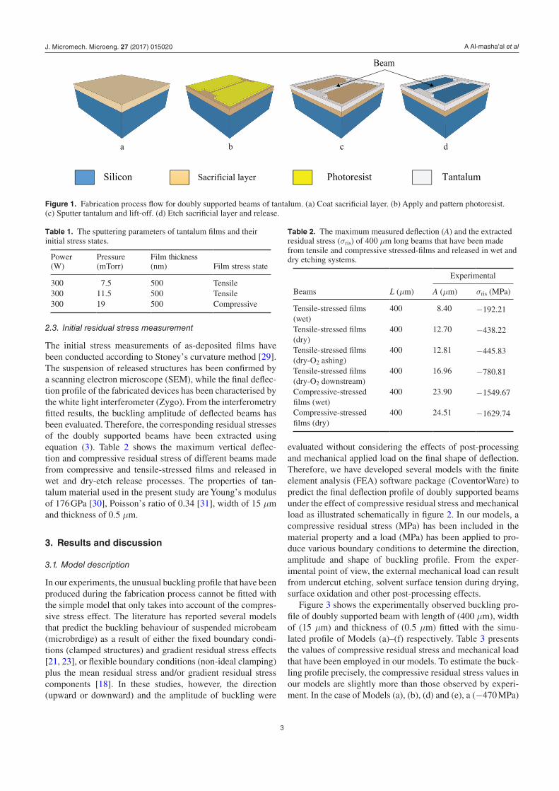
Figure 1 shows the fabrication process flow for the beams. Surface micromachining methods have been used to fabri-cate doubly supported beams on a 4 inch p-type (1 0 0) silicon wafer. Polyimide and plasma-enhanced chemical vapour deposition (PECVD) of silicon oxide (SiO2) have been used as sacrificial layers. Table 1 shows the deposition conditions, thicknesses and the initial stress states of the deposited films.
2.1. Beams fabrication
For the first sacrificial layer, about 8 µm of polyimide has been spin coated (figure 1(a)) and soft-baked on hotplate at 90 °C and 150 °C for 90 s. To remove any solvents and imidize the polyimide completely, the films have been cured at 350 °C for 30 min by increasing the temperature slowly at 4 °C min−1 and holding the sample at 350 °C for 30 min and then cooling
down to room temperature. Afterwards, a 3 µm of photoresist has been coated and patterned photolithographically (figure 1(b)). Tantalum films with thickness of 500 nm have been deposited using DC magnetron sputtering system, according the sputtering parameters presented in table 1. Once the depo-sition step has been performed, lift-off process has taken place to define the doubly supported beams thus exposing the poly-imide layer underneath the metal (figure 1(c)). Thereafter, the structure has been released (figure 1(d)) by etching the poly-imide with two dry etching systems; oxygen plasma-ashing using Barrel Asher and oxygen plasma-downstreaming using MEMSSTAR tool.
For the second sacrificial layer, a PECVD system has been employed to grow a (~3 µm) layer of low temperature SiO2 at 120 °C. The same photolithography and deposition pro-cesses as in the polyimide case have been applied. The oxide layer has been etched isotropically by a wet etching process in a diluted buffered hydrofluoric acid (BHF). Following the etching step, the samples have been transferred and soaked in the following order in deionized water for 10 min, isopropanol (IPA) for 5 min and methanol for 10 min. The final release stage has been carried out in the critical point dryer chamber and left to dry. Doubly supported beams with widths of 15 µm, thicknesses of 500 nm and lengths of (100, 200, 300 and 400 µm) have been fabricated.
2.2. Buckling analysis
Due to the stringent configuration of the fixed ends of doubly supported beams, the axial residual stress cannot be relaxed. However, the buckling takes place when the axial load exceeds the Euler buckling limit PC and the beam will be under com-pressive stress [23]:
π=P
EI
L
4C
2
2 (1)
where (L) and (EI ) are respectively the length and flexural rigidity of the beam. The buckling occurs at a particular length according to the critical stress ( σcr ) [25]:
σπ
=E t
L3cr
2 2
2 (2)
where (E, t, L) denote respectively the elastic modulus, thick-ness and length of the beam. Therefore, once the beam is released from the substrate, it will buckle according to the magnitude of the residual stress (σris) as follows [26]:
⎡⎣⎢
⎤⎦⎥
σπ
= − +E
L
A t
4 3ris
2
2
2 2
(3)
where (A) is the amplitude of buckling that can be measured interferometrically. The sinusoidal shape of buckling profile can be described as [27, 28]:
( ) / ⩽ ⩽ /⎜ ⎟⎛⎝
⎞⎠
π= − −y x
A xL x L
21 cos
2
L, 2 2 (4)
where (y) and (x) represent respectively the deflection and position along the beam.
J. Micromech. Microeng. 27 (2017) 015020
A Al-masha’al et al
3
2.3. Initial residual stress measurement
The initial stress measurements of as-deposited films have been conducted according to Stoney’s curvature method [29]. The suspension of released structures has been confirmed by a scanning electron microscope (SEM), while the final deflec-tion profile of the fabricated devices has been characterised by the white light interferometer (Zygo). From the interferometry fitted results, the buckling amplitude of deflected beams has been evaluated. Therefore, the corresponding residual stresses of the doubly supported beams have been extracted using equation (3). Table 2 shows the maximum vertical deflec-tion and compressive residual stress of different beams made from compressive and tensile-stressed films and released in wet and dry-etch release processes. The properties of tan-talum mat erial used in the present study are Young’s modulus of 176 GPa [30], Poisson’s ratio of 0.34 [31], width of 15 µm and thickness of 0.5 µm.
3. Results and discussion
3.1. Model description
In our experiments, the unusual buckling profile that have been produced during the fabrication process cannot be fitted with the simple model that only takes into account of the compres-sive stress effect. The literature has reported several models that predict the buckling behaviour of suspended microbeam (microbrdige) as a result of either the fixed boundary condi-tions (clamped structures) and gradient residual stress effects [21, 23], or flexible boundary conditions (non-ideal clamping) plus the mean residual stress and/or gradient residual stress components [18]. In these studies, however, the direction (upward or downward) and the amplitude of buckling were
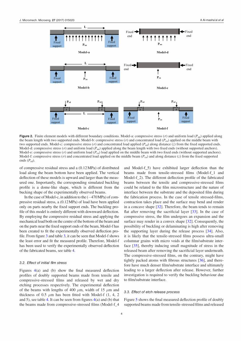
evaluated without considering the effects of post-processing and mechanical applied load on the final shape of deflection. Therefore, we have developed several models with the finite element analysis (FEA) software package (CoventorWare) to predict the final deflection profile of doubly supported beams under the effect of compressive residual stress and mechanical load as illustrated schematically in figure 2. In our models, a compressive residual stress (MPa) has been included in the material property and a load (MPa) has been applied to pro-duce various boundary conditions to determine the direction, amplitude and shape of buckling profile. From the exper-imental point of view, the external mechanical load can result from undercut etching, solvent surface tension during drying, surface oxidation and other post-processing effects.
Figure 3 shows the experimentally observed buckling pro-file of doubly supported beam with length of (400 µm), width of (15 µm) and thickness of (0.5 µm) fitted with the simu-lated profile of Models (a)–(f) respectively. Table 3 presents the values of compressive residual stress and mechanical load that have been employed in our models. To estimate the buck-ling profile precisely, the compressive residual stress values in our models are slightly more than those observed by experi-ment. In the case of Models (a), (b), (d) and (e), a (−470 MPa)
Figure 1. Fabrication process flow for doubly supported beams of tantalum. (a) Coat sacrificial layer. (b) Apply and pattern photoresist. (c) Sputter tantalum and lift-off. (d) Etch sacrificial layer and release.
Table 1. The sputtering parameters of tantalum films and their initial stress states.
Power (W)
Pressure (mTorr)
Film thickness (nm) Film stress state
300 7.5 500 Tensile300 11.5 500 Tensile300 19 500 Compressive
Table 2. The maximum measured deflection (A) and the extracted residual stress (σris) of 400 µm long beams that have been made from tensile and compressive stressed-films and released in wet and dry etching systems.
Beams L (µm)
Experimental
A (µm) σris (MPa)
Tensile-stressed films (wet)
400 8.40 −192.21
Tensile-stressed films (dry)
400 12.70 −438.22
Tensile-stressed films (dry-O2 ashing)
400 12.81 −445.83
Tensile-stressed films (dry-O2 downstream)
400 16.96 −780.81
Compressive-stressed films (wet)
400 23.90 −1549.67
Compressive-stressed films (dry)
400 24.51 −1629.74
J. Micromech. Microeng. 27 (2017) 015020
A Al-masha’al et al
4
of compressive residual stress and a (0.12 MPa) of distributed load along the beam bottom have been applied. The vertical deflection of these models is upward and larger than the meas-ured one. Importantly, the corresponding simulated buckling profile is a dome-like shape, which is different from the bucking shape of the experimentally observed beams.
In the case of Model-c, in addition to the (−470 MPa) of com-pressive residual stress, a (0.12 MPa) of load have been applied only on parts nearby the fixed support ends. The buckling pro-file of this model is entirely different with downward deflection. By employing the compressive residual stress and applying the mechanical load both on the centre of the bottom of the beam and on the parts near the fixed support ends of the beam, Model-f has been created to fit the experimentally observed deflection pro-file. From figure 3 and table 3, it can be seen that Model-f shows the least error and fit the measured profile. Therefore, Model-f has been used to verify the experimentally observed deflection of the fabricated beams, see table 4.
3.2. Effect of initial film stress
Figures 4(a) and (b) show the final measured deflection profiles of doubly supported beams made from tensile and compressive-stressed films and released by wet and dry etching processes respectively. The experimental deflection of the beams with lengths of 400 µm, width of 15 µm and thickness of 0.5 µm has been fitted with Model-f (1, 4, 2 and 5), see table 4. It can be seen from figures 4(a) and (b) that the beams made from compressive-stressed films (Model-f_4
and Model-f_5) have exhibited larger deflection than the beams made from tensile-stressed films (Model-f_1 and Model-f_2). The different deflection profile of the fabricated beams between the tensile and compressive-stressed films could be related to the film microstructure and the nature of interface between the substrate and the deposited film during the fabrication process. In the case of tensile stressed-films, contraction takes place and the surface may bend and render in a concave shape [32]. Therefore, the beam tends to remain flat after removing the sacrificial layer [33]. In the case of compressive stress, the film undergoes an expansion and the surface may render in a convex shape [32]. Consequently, the possibility of buckling or delaminating is high after removing the supporting layer during the release process [34]. Also, it is likely that the tensile-stressed films possess ultra-small columnar grains with micro voids at the film/substrate inter-face [35], thereby inducing small magnitude of stress in the released beam after removing the sacrificial layer underneath. The compressive-stressed films, on the contrary, might have tightly packed atoms with fibrous structures [36], and there-fore have much denser film/substrate interface and ultimately leading to a larger deflection after release. However, further investigation is required to verify the buckling behaviour due to film/substrate interface.
3.3. Effect of etch release process
Figure 5 shows the final measured deflection profile of doubly supported beams made from tensile-stressed films and released
Figure 2. Finite element models with different boundary conditions. Model-a: compressive stress (σ) and uniform load (Pun) applied along the beam length with two supported ends. Model-b: compressive stress (σ) and concentrated load (Pcn) applied on the middle beam with two supported ends. Model-c: compressive stress (σ) and concentrated load applied (Ped) along distance (z) from the fixed supported ends. Model-d: compressive stress (σ) and uniform load (Pun) applied along the beam length with two fixed ends (without supported anchors). Model-e: compressive stress (σ) and uniform load (Pcn) load applied on the middle beam with two fixed ends (without supported anchors). Model-f: compressive stress (σ) and concentrated load applied on the middle beam (Pcn) and along distance (z) from the fixed supported ends (Ped).
J. Micromech. Microeng. 27 (2017) 015020

A Al-masha’al et al
5
by three different etch release methods; wet etching solution (BHF), oxygen plasma-dry etching (O2-ashing) at 70 °C and downstream oxygen plasma-dry etching (O2-downstreaming) at 200 °C with flow rate of oxygen/nitrogen (2000/100 sccm. From the maximum observed deflection, the residual stress has been extracted (using equation (3)) for both wet and dry etch release measurements and presented in table 2. FEM
simulation using Model-f has been included to predict the final bucking behaviour of the beams, see Model-f 1–3 in table 4. A good agreement between simulation and experiment can be seen clearly in figure 5. It can be seen that the beams that have been released in the dry etch release methods have exhibited larger deflection profiles than the beams released in the wet etch release technique. Our results are in good agreement with previous studies [37, 38] that have reported the influence of sacrificial materials such as photoresist and silicon on the compressive residual stress of released beam. In our study, however, new findings have shown that using various release conditions (e.g. O2-ashing and O2-downstreaming) would lead to different deformations in the final released structure even with the use of the same sacrificial material (e.g. poly-imide in this study). Accordingly, the different observations of the buckled beams could only be explained in terms of etch release mechanism.
Temperature can be influential during the etch release pro-cess. Since the wet etch release has been performed at room temperature, further stress that may be introduced through
Figure 3. Comparison of deflection profiles of six developed models (dotted line) with the final measured deflection (solid line) of 400 µm-long beams.
Table 3. Comparison of the maximum vertical deflection (A) simulated with the models using compressive stress (σ) and concentrated (Pcn) or uniform (Pun) load on the bottom and load applied on the edges (Ped) of the beam.
Model
Simulation
(MAE)aL (µm)σ (MPa) ≈ experiment Pun (MPa) Pcn (MPa) Ped (MPa) A (µm)
Model-a 400 −470 0.12 — — 14.42 2.27Model-b 400 −470 — 0.12 — 13.68 1.12Model-c 400 −470 — — 0.12 −8.73 12.97Model-d 400 −470 0.12 — — 14.71 3.46Model-e 400 −470 — 0.12 — 13.78 1.38Model-f 400 −470 — 0.12 0.045 12.87 0.18
a Mean absolute error (MAE) included to compare the fitting of each model with the experiment.
Table 4. The simulated vertical deflection (A) of Model-f using different values of compressive stress (σ) and applied load on bottom (Pcn) and edges (Ped) of the beam.
Model
Simulation
L (µm)
σ (MPa) ≈ experiment
Pcn (MPa)
Ped (MPa)
A (µm)
Model-f_1 400 −200 0.50 0.15 8.43Model-f_2 400 −470 0.12 0.045 12.85Model-f_3 400 −825 0.27 0.11 16.83Model-f_4 400 −1675 0.55 0.15 24.09Model-f_5 400 −1760 0.55 0.15 24.74
J. Micromech. Microeng. 27 (2017) 015020

A Al-masha’al et al
6
high temperature processes can be avoided. In contrast, the higher temperatures in the dry etch process (200 °C in the O2-downstreaming compared to 70 °C for O2-ashing) might have considerable influence on the released structure. Compared to our observations, Fang et al [20] have shown that the shape and the direction of buckling can be controlled by focusing the dry NH3 plasma treatment on central and sided regions of the microbeam. In fact, their findings support our model assump-tion (Model-f) of employing the mechanical load that have been applied on the central and sided parts of the beam. By varying the position and the magnitude of the applied load, shapes and amplitudes of buckling can be tuned as shown in the model description (section 3.1). Typically, these results reveal how the etch release process can play an important role in determining the final deflection profile of the fabricated device.
3.4. Effect of beam dimension
Figure 6 shows the measured and simulated buckling profile along the position of doubly supported beams with lengths
ranging from 100 to 400 µm. The experimental values of com-pressive stress have been used together with the applied loads in Model-f to simulate the final deflection profile as a function of beam length, see table 5. The simulated buckling profiles of each beam are in good agreement with those obtained by exper-iment. Also, it is worth mentioning that the results of deflection profile as a function of the beam length in our work are in good
Figure 5. The final simulated (Model-f) and measured deflection of the beams made from tensile stressed-films and released in wet and dry etching processes.
Figure 6. The final simulated (Model-f) and measured deflection of the beams with length of 100–400 µm made from compressive stressed-films and released in the dry etching process.
Table 5. The simulated deflection (A) of Model-f using different values of compressive stress (σ) and applied load on centre (Pcn) and edges (Ped) for different lengths of doubly supported beams with width of 15 µm and thickness of 0.5 µm.
Model/beam length L (µm)
Experimental/ simulated stress σ (MPa)
Simulation
Pcn (MPa)
Ped (MPa)
A (µm)
Model-f/100 −1425 2.0 0.4 5.74Model-f/200 −1125 1.2 0.4 10.47Model-f/300 −1260 1.0 0.4 16.17Model-f/400 −1760 0.12 0.045 24.74
Figure 4. The final simulated (Model-f) and measured deflection of the beams made from tensile and compressive stressed-films and released in (a) wet and (b) dry etching systems.
J. Micromech. Microeng. 27 (2017) 015020

A Al-masha’al et al
7
agreement with other studies for other materials [15, 24]. It can be seen that the amplitude of deflection (A) increases as the beam length increases. It is likely that the change in the deflection profile with the beam length could be attributed to the boundary conditions effects. For example, to fit the experiment, our simulations show that the 100 µm-long beam requires more compressive stress and centre load than the 200 or 300 µm-long beams. In other studies, for example, the bending moment due to boundary configuration effects can have an influential role in determining the beam deflection-length relationship [23]. In addition, the beam stiffness has been found to decrease with increasing in the beam length [39], and therefore longer beams tend to buckle more than shorter ones.
Figure 7 shows the measured and simulated buckling pro-file along the position of doubly supported beams with length of 400 µm, thicknesses of 0.5 and 1 µm and widths of 15 and 20 µm respectively. Table 6 presents the values of ver-tical deflection and compressive residual stress that have been measured experimentally and used together with the applied loads in Model-f to simulate the final deflection profile. In order to determine the accuracy of our model, the same values of compressive stress (from experiment) and external loads have been applied on beams with same length (400 µm) but different widths (15 and 20 µm) and thicknesses (0.5 and 1 µm). From figure 7, it can be seen that thicker beams tend to buckle largely than thinner ones. It is possible that the residual stress may vary through the film’s thickness [27]. For beams with same length and widths, the simulations results presented
in table 6 have shown that the 1 µm-thick beams experience higher compressive residual stress and external loads than the 0.5 µm-thick beams. However, for beams with same length and thickness but different widths, the deflection profile has been found to be almost independent of beam width. Despite the slight variations of the experimental vertical deflection between 15 and 20 µm-wide beams with the same length and thickness, the simulations have shown that the vertical
Figure 7. The final simulated (Model-f) and measured deflection of the beams made from tensile stressed-films and released in the dry etching process. The beams dimensions are: (a) L = 400 µm, T = (0.5, 1 µm) and W = 15 µm; (b) L = 400 µm, T = (0.5, 1 µm) and W = 20 µm.
Table 6. The vertical deflection (A) of Model-f using different values of compressive stress (σ) and applied load on centre (Pcn) and edges (Ped) for beams with lengths (L) of 400 µm, widths (W) of 15 and 20 µm and thicknesses (T ) of 0.5 and 1 µm.
L (µm) W (µm) T (µm)Measured A (µm)
Measured σ (MPa)
Simulation
σ (MPa) Pcn (MPa) Ped (MPa) A (µm)
400 15 0.5 12.92 −453.50 −453.50 0.13 0.05 12.83400 15 1 18.82 −914.16 −914.16 0.70 0.15 18.83400 20 0.5 12.28 −453.50 −453.50 0.13 0.05 12.83400 20 1 18.33 −914.16 −914.16 0.70 0.15 18.83
Figure 8. Typical SEM images of doubly supported beams of tantalum that have been made from tensile stressed-films and released by the wet etching method.
J. Micromech. Microeng. 27 (2017) 015020
A Al-masha’al et al
8
deflection and buckling profile of these beams are entirely identical, see table 6.
The aforementioned results have shown that the amplitude and shape of buckled beams depend on the residual stress, etch release process, boundary conditions and beam length. An optimum profile has been obtained for suspended tantalum beams that have been made from tensile stressed-film and released in the wet etching process as shown in figure 8 with an aspect ratio of 1:48.
4. Conclusion
The paper presents the optimisation of the design and fabri-cation of an array of suspended microstructures of tantalum using surface micromachining methods. The impact of wet etch and dry etch release processes on the final deflection pro-files of the doubly supported beams that have been made from compressive and tensile-stressed films has been investigated. The doubly supported beams made from tensile-stressed films have exhibited the least vertical deflection. More importantly, the wet etch release approach has produced smaller deforma-tion in the final fabricated devices than the dry etch release methods. Furthermore, an optimised FE model has been devel-oped to predict the buckling behaviour of doubly supported beams by including the effects of compressive residual stress and applied loads in the centre and at the edges of the beam as boundary conditions. An optimum profile of the suspended microstructures of tantalum with an aspect ratio of 1:48 has been obtained from the tensile-stressed films that have been released by the wet etching method. The results produced in this work provide useful information about the fabrication-induced stress effects of micro-suspended devices and can be used for the optimisation of the design and manufacturing of MEMS-based materials and devices.
Acknowledgments
We acknowledge the financial support of UK Engineering and Physical Sciences Research Council (EPSRC) for this work. The Ministry of Higher Education and Scientific Research (MOHESR) of Iraq is acknowledged for the financial support through the PhD scholarship programme.
References
[1] Luo Z Y, Chen D Y and Wang J B 2014 A SOI-MEMS based resonant barometric pressure sensor with differential output Key Eng. Mater. 609–10 1033–9
[2] Luo Z, Chen D, Wang J, Li Y and Chen J 2014 A high-Q resonant pressure microsensor with through-glass electrical interconnections based on wafer-level MEMS vacuum packaging Sensors 14 24244–57
[3] Kalambe J and Patrikar R 2015 Design, fabrication, and characterization of electrostatically actuated microcantilever sensor for temperature detection IEEE Sens. J. 15 1595–601
[4] Medina L, Gilat R, Ilic B and Krylov S 2014 Experimental investigation of the snap-through buckling of
electrostatically actuated initially curved pre-stressed micro beams Sensors Actuators A 220 323–32
[5] Somà A and Saleem M M 2015 Modeling and experimental verification of thermally induced residual stress in RF-MEMS J. Micromech. Microeng. 25 055007
[6] Yao J J 2000 RF MEMS from a device perspective J. Micromech. Microeng. 10 R9–38
[7] Latif R, Mastropaolo E, Bunting A, Cheung R, Koickal T, Hamilton A, Newton M and Smith L 2010 Microelectromechanical systems for biomimetical applications J. Vac. Sci. Technol. B 28 C6N1
[8] Latif R, Mastropaolo E, Bunting A, Cheung R, Koickal T, Hamilton A, Newton M and Smith L 2011 Low frequency tantalum electromechanical systems for biomimetical applications J. Vac. Sci. Technol. B 29 06FE05
[9] Brand O, Dufour I, Heinrich S M and Josse F 2015 Resonant MEMS, Fundamentals, Implementation and Application (Weinheim: Wiley-VCH) (doi: 10.1002/9783527676330)
[10] Mastropaolo E, Latif R, Grady E and Cheung R 2013 Control of stress in tantalum thin films for the fabrication of 3D MEMS structures J. Vac. Sci. Technol. B 31 06FD02
[11] Sharpe W N 2008 Springer Handbook of Experimental Solid Mechanics (Berlin: Springer)
[12] Hou M T-K and Chen R 2004 A new residual stress measurement method using ultra-wide micromachined bilayer cantilevers J. Micromech. Microeng. 14 490–6
[13] Sun C, Zhou Z-F, Li W-H and Huang Q-A 2014 A simple method for extracting material parameters of multilayered MEMS structures using resonance frequency measurements J. Micromech. Microeng. 24 075014
[14] Luo C, Francis A and Liu X 2008 Determination of compressive residual stress in a doubly-clamped microbeam according to its buckled shape Microelectron. Eng. 85 339–47
[15] Kobrinsky M J, Deutsch E R and Senturia S D 2000 Effect of support compliance and residual stress on the shape of doubly supported surface-micromachined beams J. Microelectromech. Syst. 9 361–9
[16] Yu Y-T, Yuan W-Z, Qiao D-Y and Liang Q 2008 Evaluation of residual stresses in thin films by critical buckling observation of circular microstructures and finite element method Thin Solid Films 516 4070–5
[17] Zhang D and Chu J 2009 Mechanical characterization of post-buckled micro-bridge beams by micro-tensile testing Microsyst. Technol. 16 375–80
[18] Fachin F, Nikles S A, Dugundji J and Wardle B L 2011 Analytical extraction of residual stresses and gradients in MEMS structures with application to CMOS-layered materials J. Micromech. Microeng. 21 095017
[19] Iwase E, Hui P-C, Woolf D, Rodriguez A W, Johnson S G, Capasso F and Lončar M 2012 Control of buckling in large micromembranes using engineered support structures J. Micromech. Microeng. 22 065028
[20] Su W S, Lee S T, Lin C Y, Yip M C, Tsai M S and Fang W 2006 Control the shape of buckling micromachined beam using plasma chemistry bonding technology Japan. J. Appl. Phys. 45 8479–83
[21] Fang W and Wickert J A 1996 Determining mean and gradient residual stresses in thin films using micromachined cantilevers J. Micromech. Microeng. 6 301–9
[22] Schöngrundner R, Treml R, Antretter T, Kozic D, Ecker W, Kiener D and Brunner R 2014 Critical assessment of the determination of residual stress profiles in thin films by means of the ion beam layer removal method Thin Solid Films 564 321–30
[23] Fang W, Lee C-H and Hu H-H 1999 On the buckling behavior of micromachined beams J. Micromech. Microeng. 9 236–44
J. Micromech. Microeng. 27 (2017) 015020
A Al-masha’al et al
9
[24] Zhou Z, Zhou Y, Cao Y and Mao H 2007 Residual strain of a Cr film characterized by micromachined beams Meas. Sci. Technol. 18 3399–402
[25] Anon 2006 Micromachined Thin-Film Sensors for SOI-CMOS Co-Integration (Berlin: Springer) (doi: 10.1007/0-387-28843-0)
[26] Masters N, de Boer M, Jensen B, Baker M and Koester D 2001 Mechanical Properties of Structural Films ed C Muhlstein and S Brown (Conshohocken, PA: ASTM International) (doi: 10.1520/STP1413-EB)
[27] Fang W and Wickert J A 1994 Post-buckling of micromachined beams Proc. IEEE Micro Electro Mechanical Systems an Investigation of Micro Structures, Sensors, Actuators, Machines and Robotic Systems (IEEE) pp 182–7
[28] Masters N D, De Boer M P, Jensen B D, Baker M S and Koester D 2001 Side-by-side comparison of passive MEMS strain test structures under residual compression ASTM Special Technical Publication (ASTM International) pp 168–200
[29] Stoney G G 1909 The tension of metallic films deposited by electrolysis Proc. R. Soc. A 82 172–5
[30] Guisbiers G, Herth E, Buchaillot L and Pardoen T 2010 Fracture toughness, hardness, and Young’s modulus of tantalum nanocrystalline films Appl. Phys. Lett. 97 143115
[31] Cardarelli F 2008 Materials Handbook: a Concise Desktop Reference vol 150 (Berlin: Springer) (doi: 10.1038/150195b0)
[32] Madou M J 2002 Fundamentals of Microfabrication: the Science of Miniaturization 2nd edn (Boca Raton, FL: CRC Press)
[33] Pruessner M W, King T T, Kelly D P, Grover R, Calhoun L C and Ghodssi R 2003 Mechanical property measurement of InP-based MEMS for optical communications Sensors Actuators A 105 190–200
[34] Freund L B and Suresh S 2004 Thin Film Materials: Stress, Defect Formation and Surface Evolution (Cambridge: Cambridge University Press)
[35] Clevenger L A, Mutscheller A, Harper J M E, Cabral C and Barmak K 1992 The relationship between deposition conditions, the beta to alpha phase transformation, and stress relaxation in tantalum thin films J. Appl. Phys. 72 4918
[36] Thornton J A 1977 Internal stresses in titanium, nickel, molybdenum, and tantalum films deposited by cylindrical magnetron sputtering J. Vac. Sci. Technol. 14 164
[37] Peroulis D, Pacheco S P, Sarabandi K and Katehi L P B 2003 Electromechanical considerations in developing low-voltage RF MEMS switches IEEE Trans. Microw. Theory Tech. 51 259–70
[38] Garg A, Small J, Liu X, Mahapatro A K and Peroulis D 2009 Impact of sacrificial layer type on thin-film metal residual stress Sensors, 2009 IEEE pp 1052–5
[39] Peters T-J and Tichem M 2015 Fabrication and characterization of suspended beam structures for SiO2 photonic MEMS J. Micromech. Microeng. 25 105003
J. Micromech. Microeng. 27 (2017) 015020