edited driver checker guide - bndhep.net
TRANSCRIPT

The Guide

Page 2 of 8
Welcome to the not-at-all comprehensive guide to testing and troubleshooting an A2071 driver. This guide covers both the Ethernet Drivers (A20171E) and VME Drivers (A2071A). The biggest differences between the two (in the troubleshooting department at least) are the nature in which the driver draws power and the use of a Rabbit module on the Ethernet driver. This guide should cover most the basic/common problems that could prevent a driver from functioning; however, drivers being as complex as they are, many problems are unique and hence not covered here. In such cases the oscilloscope and schematics are your best friends. The appendix has tips for testing and working with such drivers. That said, lets dive in! 1. When setting up the Ethernet drivers for testing, plug the driver into power and a
computer via its Ethernet port. If it turns on, as indicated by the green status lights, go to step 5. If it does not turn on, proceed to step 2. When setting up the VME Drivers for testing, plug the VME Driver into a VME crate and connect your computer to the interfacial VME board. When you plug your board into the VME crate the green status lights should turn on (assuming the board is unprogrammed). Give your driver a base address, which you can do by moving the white switches on S3 from the right to the left. The top 4 switches are the ones to move and they each represent a number in binary, starting at switch 4. i.e. when you move only switch 4 to the left, you have a base address of 00100000, when you move only switch 3 to the left you have a base address of 00200000. See here for clarification. (On the new LWDAQ firmware the base address can be expressed as 10, 20, 30 and so on). If just one of the lights doesn't work, go to Step 5.
2. Make sure you turned on the power pack supplying power to the Ethernet Driver and set it to ~24V. If this wasn’t the issue, proceed to step 3; if it was your issue, don’t feel bad, (it happens often enough for me to put it in here) and proceed to step 5.
3. The next thing to check on the Ethernet Driver would be the bridge rectifier located at U8. It’s currently the DF01S and is often oriented incorrectly. If correctly placed, the plus symbol should be in the top left corner. If not, correct it, and it should turn on. If this was your issue, proceed to step 6.
4. Check the packages on L1, L2, and L3. These are hard (impossible) to misalign; however, ensure that L2 and L3 haven't been interchanged (they look slightly similar). If your board still refuses to power up, you are now in the “unique and hence uncovered” territory. In the appendix are some tips for testing and working with stubborn drivers. Click here.
5. If one of the three green lights doesn’t turn on, check that the test pins on the bottom of the board, labeled +15V, +15VH, -15V, -15VH, +5V and +5VH, are connected to +15 V, -15 V and +5 V using the oscilloscope. If they aren’t, check that the packages on L2 and L3 are at the values specified on the schematics. If those are giving the correct values, check that the transistors to which they are connected (specified on the
Page 3 of 8
schematics, but if you are unsure of the value, compare the values on each pin to the values on a working board). Else, you are now probably in the “unique and hence uncovered” territory. In the appendix are some tips for testing and working with stubborn drivers.
6. If your board turns on, program it and proceed to step 8. If it doesn't program, go to step 7. Special note on programming VME Drivers: First program the larger logic chip located on U1. Program this chip using the P2 programmer pins using the most recent version of the A2071E firmware. (The green power lights should turn off once programmed). Next, program the smaller logic chip located on U32. Use the P8 programmer pins and should program this chip with the most recent version of A2071A firmware. You cannot program the chips interchangeably, so it is impossible to confuse the two firmware.
7. Chances are if the logic chip isn’t programming there are dry pins. The usual suspects are the first few pins at the bottom left and right face of the chip. If the Ethernet Driver’s Rabbit Module isn’t programming, you probably have dry pins on your Rabbit connector. The Rabbit programming software is a little finicky so confirm that it’s working on another driver before assuming your board has an issue. Once your board is programmed move to the next step.
8. Launch LWDAQ on the computer connected to your driver and open the “Configurator” tool and, if you are testing a VME Driver, the “Diagnostic” instrument. Additionally, launch the “Driver Checker” tool through “Run Tool”. You can download it here.
9. With the VME Driver, open Diagnostic and type 10.0.0.37 into the daq_ip_addr and 00x00000:1 (x being whatever number you have chosen for your base address) into daq_driver_socket. Turn the board on. If the board does not turn on, go to Step 10. If it does, go to step 11.
10. If the board does not turn on when you press the Head Power On button in Diagnostic, check the oscillator. Make sure that it is aligned correctly and if it is, that it is oscillating correctly. (You can do this by touching each pin with the oscilloscope, or just checking the FCK pin which should oscillate at 80 MHz). If this does not fix the problem, check for dry pins on the two logic chips. Else, you are now probably in the “unique and hence uncovered” territory. In the appendix are some tips for testing and working with stubborn drivers.
Page 4 of 8
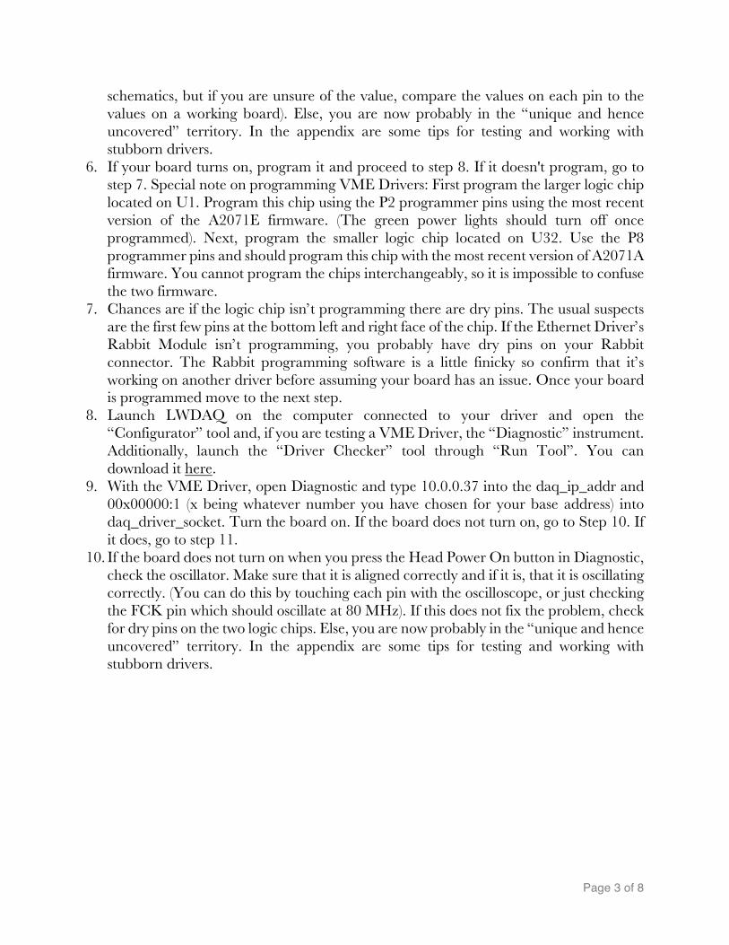
11. In Configurator, attempt to contact the driver. With the Ethernet Drivers, the contact_base_addr should be 00000000. However, the VME Driver should have the contact_base_addr matching your chosen 00x00000. You should get something like this in the window:
12. If the Hardware Version is something other than 2, remove R13 from your board and
leave it open (Only on the Ethernet Board!!). Version 2 is what we use for our current build. The small table printed on the board next to R12 and R13 can help you set your board to any other hardware version we may use in the future.
13. If any of the other numbers don’t line up, the next few tests should help indicate a course of action. (Note: The MAC Address is unique to every driver and will change.)
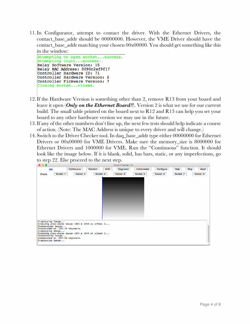
14. Switch to the Driver Checker tool. In daq_base_addr type either 00000000 for Ethernet Drivers or 00x00000 for VME Drivers. Make sure the memory_size is 8000000 for Ethernet Drivers and 1000000 for VME. Run the “Continuous” function. It should look like the image below. If it is blank, solid, has bars, static, or any imperfections, go to step 22. Else proceed to the next step.
Page 5 of 8
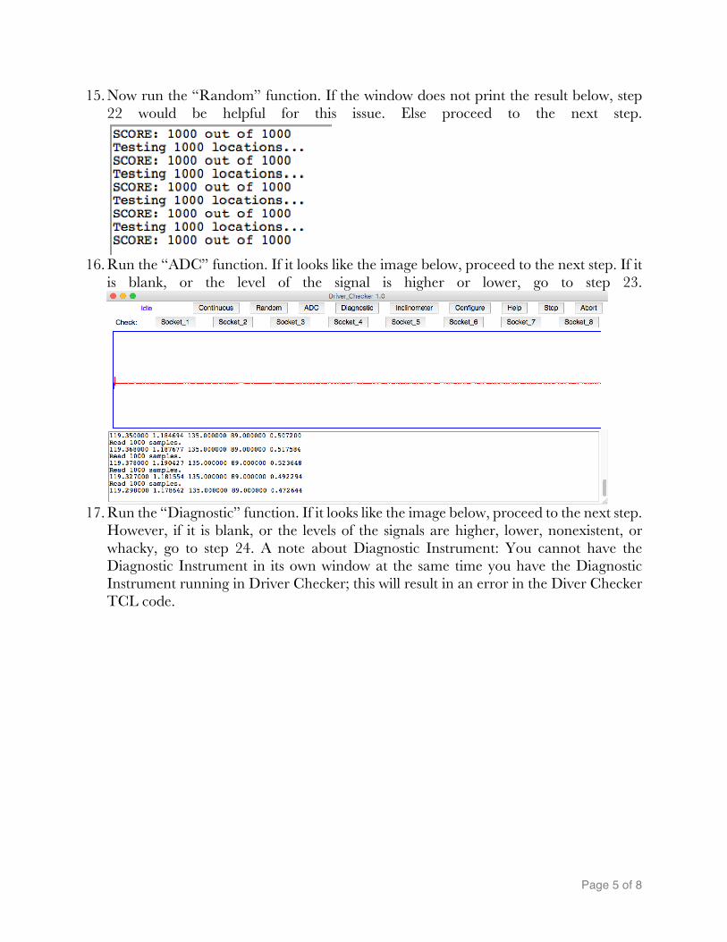
15. Now run the “Random” function. If the window does not print the result below, step 22 would be helpful for this issue. Else proceed to the next step.
16. Run the “ADC” function. If it looks like the image below, proceed to the next step. If it
is blank, or the level of the signal is higher or lower, go to step 23.
17. Run the “Diagnostic” function. If it looks like the image below, proceed to the next step.
However, if it is blank, or the levels of the signals are higher, lower, nonexistent, or whacky, go to step 24. A note about Diagnostic Instrument: You cannot have the Diagnostic Instrument in its own window at the same time you have the Diagnostic Instrument running in Driver Checker; this will result in an error in the Diver Checker TCL code.

Page 6 of 8
18. Sequentially connect a camera to each socket on the driver, selecting the respective
channel on the Driver Checker. If all the channels present the same problem or don’t work, go to step 25. If most of the channels work but a few do not, go to step 26 to troubleshoot these individual problems. If you are working with an Ethernet Driver and the cameras work, go to step 20.
19. The last step for the VME Drivers is to plug another VME Driver into the VME crate and make sure it works. You can do this a number of ways: plugging in a BCAM/Injector and running the “BCAM” function on the newly plugged in VME Driver, running the “Diagnostic” function, or checking the cameras. If the newly plugged in VME driver works, go to step 20. If not, check for dry pins on the small logic chip (U32) on the original VME Driver. If there are no dry pins, I recommend probing the small logic chip with the oscilloscope to verify that it is the problem and that it must be changed. Else, you are now probably in the “unique and hence uncovered” territory. In the appendix are some tips for testing and working with stubborn drivers.
20. If your driver has passed all the tests above, well done! Go to step 21. If the driver didn’t pass the tests but the subsequent steps to which the above steps are linked helped you to fix your driver and then pass the test, well done! Go to step 21. If your driver hasn’t passed these tests and this guide failed to help, you are now in the “unique and hence uncovered” territory. In the appendix are some tips for testing and working with stubborn drivers. Click here.
21. Switch back to the Configurator tool and press “Read” and then “Copy.” In the column on the right enter all the relevant information. If the driver is not going on the network, enter the Driver ID and the Operator name for now to see if this is working. Once entered, hit Write, then Reboot, then Read. If this fails, make sure you’ve reset the EEPROM on the driver. If this doesn't work, step 22 may help. If it did work, well done! Your driver is now complete; put it in a box ASAP so that it doesn't get damaged lying around in the lab.
22. Chances are, if you’ve landed on this step you have a dry pin or a short on your RAM chips or the pins they connect to on the logic chip. Start by inspecting the RAM chips: U3, U4, U5, and U6. If you locate no dry pins or shorts here, check the top face of the

Page 7 of 8
logic chip next; this is where most of the RAM signals run. If you locate no dry pins or shorts here either, check the pins on the bottom face of the logic chip and the pins on the Rabbit connector. It is less likely that these symptoms would emerge from an error here, but it is possible. If you do locate such an issue, fix it and return to the step that brought you here and proceed from there. Else, you are now probably in the “unique and hence uncovered” territory. In the appendix are some tips for testing and working with stubborn drivers. Click here.
23. Chances are, if you’ve landed on this step you have a dry pin or a short on your ADC chips or the pins that they connect to on the logic chip. Start by inspecting the ADC chips: U22 and U23. If you locate no dry pins or shorts here check the right face of the logic chip; this is where most of the ADC signals run. If you do locate such an issue, fix it and return to the step that brought you here and proceed from there. Else, you are now probably in the “unique and hence uncovered” territory. In the appendix are some tips for testing and working with stubborn drivers. Click here.
24. If your driver’s power levels aren't what they should be, investigate the SOT-23 packages Q2-Q6 at the bottom of your board along with the resistors surrounding them. Ensure that there are no dry pads and that none of the transistors have been switched with neighboring ones. Whacky (you’ll know it when you see it) levels may be caused by an incorrectly oriented oscillator, U7. The big dot should be in the top left corner. If you do locate such an issue, fix it and return to the step that brought you here and proceed from there. Else, you are now probably in the “unique and hence uncovered” territory. In the appendix are some tips for testing and working with stubborn drivers. Click here.
25. If your diver has passed all the tests up to this point but refuses to take images, there is a laundry list of errors that could be the culprit. Unfortunately, most would fall into the “unique and hence uncovered” category; however, some common soldering errors can be found on chips U28, U19, U18, U20, U21, and U26 (checked in that order). If you have images but they’re just distorted in one specific manner and your RAM tests came up clean, you’re probably looking for a short on one of these chips. If you do locate such an issue, fix it and return to the step that brought you here and proceed from there. In the appendix are some tips for testing and working with stubborn drivers. Click here.
26. If most of your sockets are taking images with the exception of a few to one, chances are you have dry pins or a short on the faulty channel’s DG411DY chip. If this is not the case, inspect the connector pins on the underside of the board. If neither of these is the case, check to see you haven’t mistakenly transposed the resistors on that channel. If you do locate such an issue, fix it and return to the step that brought you here and proceed from there. Else, you are now probably in the “unique and hence uncovered” territory. In the appendix are some tips for testing and working with stubborn drivers. Click here.
Page 8 of 8
The Appendix Welcome to the appendix. If you have been sent here it probably means your driver is misbehaving and my super generic solutions did nothing to help you. Fret not for with the tips below and the excellent schematics and oscilloscope you should be able to get your driver up and running in no time! If the appendix helps you solve the problem the guide sent you down here for, return to the step you came from and resume following the steps and testing your driver. If you’re still hitting a wall and your driver refuses to function as designed it is now time to contact the wizard. If he can't help you, no one can. The tips:
a. Always make sure your scope is connected to ground. Ground on this board are test pins 11 and 12. The GND pad next to the power jack is not actually a ground. If you see a 60Hz signal on your scope you’re probably not grounded.
b. Work on scales appropriate to the board, typically 100ns and 5V, but this may vary. c. Have a working driver handy to which you can compare your broken one. d. It is conceivable for chips to be transposed with others or incorrectly oriented; it is
worth inspecting suspect regions under a loupe. e. Chips U24, U30, and U31 are notorious for dry pins or shorts and can cause a host
of problems. Inspect them closely. f. A fine dental pick can be very handy in tapping suspect pins that look fine but may
be dry. Be very careful when doing this because, if bent back and forth too much, these pins are liable to break.
g. It is common for a driver’s issues to be caused by a faulty Rabbit module. Switch it out with another driver’s module and re-run the tests to eliminate this possibility.
h. Feeding a signal into the driver via the connector on P5 using a signal generator and then tracing it to the potentially faulty circuit can be a useful way of uncovering problems in a board, albeit tricky.
i. Don’t get too frustrated; it is a really good feeling when your board finally starts working. Trust me.