editing cad geodata · tributes and can be connected with complex databases. the exercises in this...
TRANSCRIPT
Tutorial
Editing CADGeodata
in
TNTmips®
and TNTedit
EDIT
CAD
™
page 2
Editing CAD Geodata
Before Getting StartedThis booklet introduces techniques for creating, altering, and updating CADgeospatial objects in the powerful Editor in TNTmips® and TNTedit™. CADobjects that you make or import contain point, line, geometric shape, and poly-gon elements in one or more drawing layers. Each element has associated at-tributes and can be connected with complex databases. The exercises in thisbooklet introduce you to the basic editing tools for CAD elements. TNT’s Editoralso has tools for editing your vector, raster, database, and TIN geodata.
Prerequisite Skills This booklet assumes that you have completed the exercisesin the tutorials Displaying Geospatial Data and TNT Product Concepts. Thoseexercises introduce essential skills and basic techniques that are not coveredagain here. Please consult those booklets and other TNT Reference Materials(installed or on MicroImages’web site) for any review you need.
Sample Data The exercises presented in this booklet use sample data that isdistributed with the TNT products. If you do not have access to a TNT productsDVD, you can download the data from MicroImages’ web site. In particular, thisbooklet uses objects in the EDITCAD Project File in the EDITCAD data collection.Make a read-write copy of that file on your hard drive; you may encounter prob-lems if you work directly with the sample data on the DVD.
More Documentation This booklet is intended only as an introduction to CADediting in TNT’s Editor. The tutorial Editing Vector Geodata is also recom-mended, since many vector editing operations are essentially the same.
TNTmips® Pro and TNTmips Free TNTmips (the Map and Image ProcessingSystem) comes in three versions: the professional version of TNTmips (TNTmipsPro), the low cost TNTmips Basic version, and the TNTmips Free version. Allversions run exactly the same code from the TNT products DVD and have nearlyall the same features. If you did not purchase the professional version (whichrequires a software license key) or TNTmips Basic, then TNTmips operates inTNTmips Free mode.
Keith Ghormley and Merri P. Skrdla, Ph.D., 21 November 2013©MicroImages, Inc., 2005–2013
It may be difficult to identify the important points in some illustrations withouta color copy of this booklet. You can print or read this booklet in color fromMicroImages’ web site. The web site is also your source for the newesttutorial booklets on other topics. You can download an installation guide,sample data, and the latest version of TNTmips Free:
http://www.microimages.com
page 3
Editing CAD Geodata
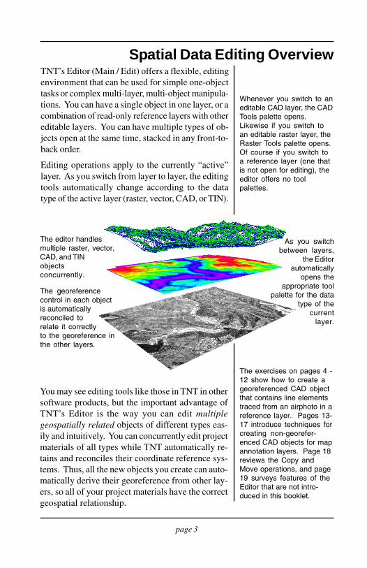
Spatial Data Editing OverviewTNT’s Editor (Main / Edit) offers a flexible, editingenvironment that can be used for simple one-objecttasks or complex multi-layer, multi-object manipula-tions. You can have a single object in one layer, or acombination of read-only reference layers with othereditable layers. You can have multiple types of ob-jects open at the same time, stacked in any front-to-back order.
Editing operations apply to the currently “active”layer. As you switch from layer to layer, the editingtools automatically change according to the datatype of the active layer (raster, vector, CAD, or TIN).
The exercises on pages 4 -12 show how to create ageoreferenced CAD objectthat contains line elementstraced from an airphoto in areference layer. Pages 13-17 introduce techniques forcreating non-georefer-enced CAD objects for mapannotation layers. Page 18reviews the Copy andMove operations, and page19 surveys features of theEditor that are not intro-duced in this booklet.
Whenever you switch to aneditable CAD layer, the CADTools palette opens.Likewise if you switch toan editable raster layer, theRaster Tools palette opens.Of course if you switch toa reference layer (one thatis not open for editing), theeditor offers no toolpalettes.
You may see editing tools like those in TNT in othersoftware products, but the important advantage ofTNT’s Editor is the way you can edit multiplegeospatially related objects of different types eas-ily and intuitively. You can concurrently edit projectmaterials of all types while TNT automatically re-tains and reconciles their coordinate reference sys-tems. Thus, all the new objects you create can auto-matically derive their georeference from other lay-ers, so all of your project materials have the correctgeospatial relationship.
The editor handlesmultiple raster, vector,CAD, and TINobjectsconcurrently.
The georeferencecontrol in each objectis automaticallyreconciled torelate it correctlyto the georeference inthe other layers.
As you switchbetween layers,
the Editorautomatically
opens theappropriate tool
palette for the datatype of the
currentlayer.
page 4
Editing CAD Geodata
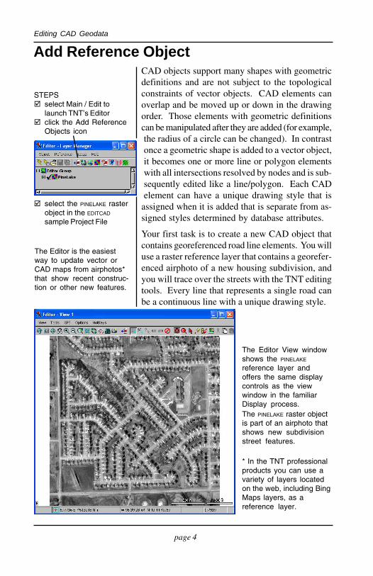
Add Reference ObjectCAD objects support many shapes with geometricdefinitions and are not subject to the topologicalconstraints of vector objects. CAD elements canoverlap and be moved up or down in the drawingorder. Those elements with geometric definitionscan be manipulated after they are added (for example,the radius of a circle can be changed). In contrastonce a geometric shape is added to a vector object,it becomes one or more line or polygon elementswith all intersections resolved by nodes and is sub-sequently edited like a line/polygon. Each CADelement can have a unique drawing style that is
assigned when it is added that is separate from as-signed styles determined by database attributes.
Your first task is to create a new CAD object thatcontains georeferenced road line elements. You willuse a raster reference layer that contains a georefer-enced airphoto of a new housing subdivision, andyou will trace over the streets with the TNT editingtools. Every line that represents a single road canbe a continuous line with a unique drawing style.
The Editor View windowshows the PINELAKE
reference layer andoffers the same displaycontrols as the viewwindow in the familiarDisplay process.
The Editor is the easiestway to update vector orCAD maps from airphotos*that show recent construc-tion or other new features.
The PINELAKE raster objectis part of an airphoto thatshows new subdivisionstreet features.
STEPS select Main / Edit to
launch TNT’s Editor click the Add Reference
Objects icon
select the PINELAKE rasterobject in the EDITCAD
sample Project File
* In the TNT professionalproducts you can use avariety of layers locatedon the web, including BingMaps layers, as areference layer.
page 5
Editing CAD Geodata
Create a CAD Object
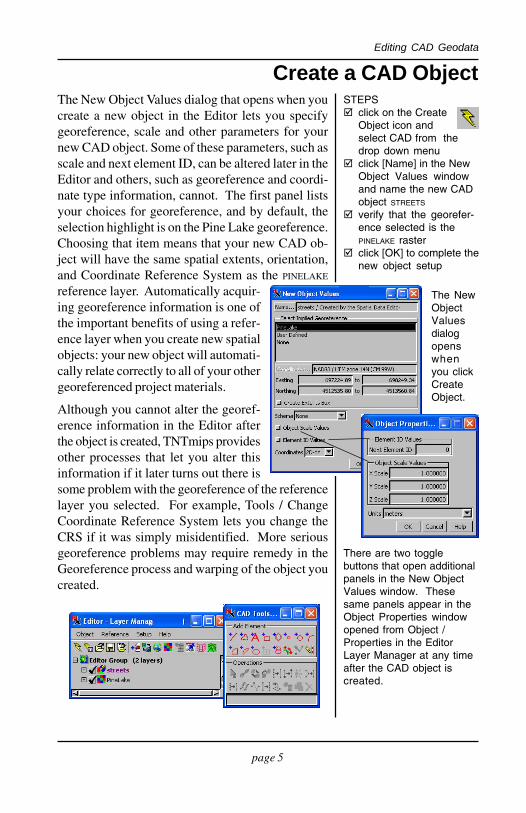
The NewObjectValuesdialogopenswhenyou clickCreateObject.
STEPS click on the Create
Object icon andselect CAD from thedrop down menu
click [Name] in the NewObject Values windowand name the new CADobject STREETS
verify that the georefer-ence selected is thePINELAKE raster
click [OK] to complete thenew object setup
The New Object Values dialog that opens when youcreate a new object in the Editor lets you specifygeoreference, scale and other parameters for yournew CAD object. Some of these parameters, such asscale and next element ID, can be altered later in theEditor and others, such as georeference and coordi-nate type information, cannot. The first panel listsyour choices for georeference, and by default, theselection highlight is on the Pine Lake georeference.Choosing that item means that your new CAD ob-ject will have the same spatial extents, orientation,and Coordinate Reference System as the PINELAKE
reference layer. Automatically acquir-ing georeference information is one ofthe important benefits of using a refer-ence layer when you create new spatialobjects: your new object will automati-cally relate correctly to all of your othergeoreferenced project materials.
Although you cannot alter the georef-erence information in the Editor afterthe object is created, TNTmips providesother processes that let you alter thisinformation if it later turns out there issome problem with the georeference of the referencelayer you selected. For example, Tools / ChangeCoordinate Reference System lets you change theCRS if it was simply misidentified. More seriousgeoreference problems may require remedy in theGeoreference process and warping of the object youcreated.
There are two togglebuttons that open additionalpanels in the New ObjectValues window. Thesesame panels appear in theObject Properties windowopened from Object /Properties in the EditorLayer Manager at any timeafter the CAD object iscreated.
page 6
Editing CAD Geodata
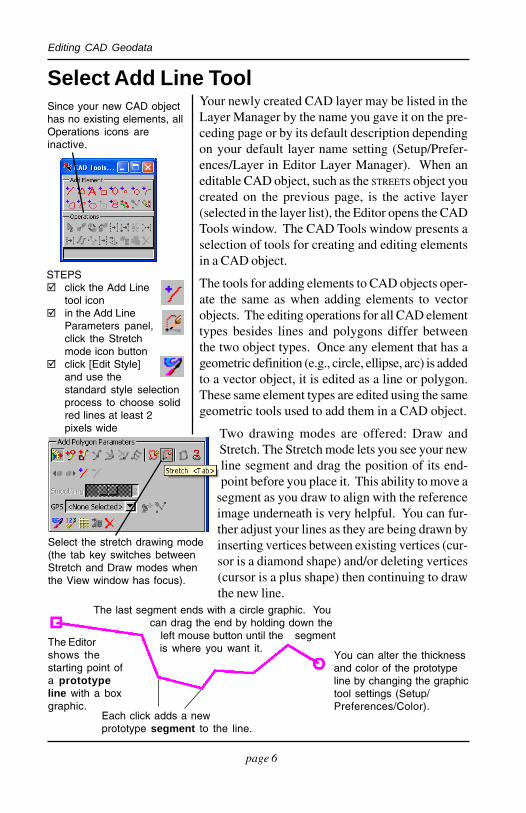
Select Add Line Tool
STEPS click the Add Line
tool icon in the Add Line
Parameters panel,click the Stretchmode icon button
click [Edit Style]and use thestandard style selectionprocess to choose solidred lines at least 2pixels wide
Your newly created CAD layer may be listed in theLayer Manager by the name you gave it on the pre-ceding page or by its default description dependingon your default layer name setting (Setup/Prefer-ences/Layer in Editor Layer Manager). When aneditable CAD object, such as the STREETS object youcreated on the previous page, is the active layer(selected in the layer list), the Editor opens the CADTools window. The CAD Tools window presents aselection of tools for creating and editing elementsin a CAD object.
The tools for adding elements to CAD objects oper-ate the same as when adding elements to vectorobjects. The editing operations for all CAD elementtypes besides lines and polygons differ betweenthe two object types. Once any element that has ageometric definition (e.g., circle, ellipse, arc) is addedto a vector object, it is edited as a line or polygon.These same element types are edited using the samegeometric tools used to add them in a CAD object.
Two drawing modes are offered: Draw andStretch. The Stretch mode lets you see your newline segment and drag the position of its end-point before you place it. This ability to move a
segment as you draw to align with the referenceimage underneath is very helpful. You can fur-ther adjust your lines as they are being drawn byinserting vertices between existing vertices (cur-sor is a diamond shape) and/or deleting vertices(cursor is a plus shape) then continuing to drawthe new line.
Since your new CAD objecthas no existing elements, allOperations icons areinactive.
The Editorshows thestarting point ofa prototypeline with a boxgraphic.
The last segment ends with a circle graphic. Youcan drag the end by holding down the
left mouse button until the segment
You can alter the thicknessand color of the prototypeline by changing the graphictool settings (Setup/Preferences/Color).
Select the stretch drawing mode(the tab key switches betweenStretch and Draw modes whenthe View window has focus).
Each click adds a newprototype segment to the line.
is where you want it.
page 7
Editing CAD Geodata
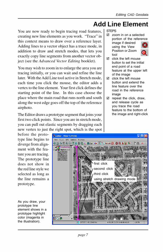
Add Line ElementYou are now ready to begin tracing road features,creating new line elements as you work. “Trace” inthis context means to draw over a reference layer.Adding lines to a vector object has a trace mode, inaddition to draw and stretch modes, that lets youexactly copy line segments from another vector ob-ject (see the Advanced Vector Editing booklet).
You may wish to zoom in to enlarge the area you aretracing initially, or you can wait and refine the linelater. With the Add Line tool active in Stretch mode,each time you click the mouse, the editor adds avertex to the line element. Your first click defines thestarting point of the line. In this case choose theplace where the main road that runs north and southalong the west edge goes off the top of the referenceairphoto.
The Editor draws a prototype segment that joins yourfirst two click points. Since you are in stretch mode,you can pull out elastic segments by dragging eachnew vertex to just the right spot, which is the spotbefore the proto-type line begins todiverge from align-ment with the fea-ture you are tracing.The prototype linedoes not show inthe red line style weselected as long asthe line remains aprototype.
As you draw, yourprototype lineelement shows in aprototype highlightcolor (magenta inthe illustration).
STEPS zoom in on a selected
portion of the referenceimage if desiredusing the ViewPosition or Zoomtool
click the left mousebutton to set the initialend point of a roadfeature at the upper leftof the image
click the left mousebutton and extend theline feature over theroad in the referenceimage
repeat the click, draw,and release cycle asyou trace the roadfeature to the bottom ofthe image and right-click
first click
second click
third click
using stretch drawing mode
page 8
Editing CAD Geodata
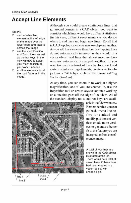
Accept Line ElementsAlthough you could create continuous lines thatgo around corners in a CAD object, you want toconsider which lines would have different attributes(in this case, different street names) as you decidewhere to end lines and begin new lines. Recall thatin CAD topology, elements may overlap one another.As you add line elements therefore, overlapping linesdo not automatically intersect as they would in avector object, and lines that almost meet are like-wise not automatically snapped together. If youwant to create a network of lines that forms a closedsystem of intersecting elements, create a vector ob-ject, not a CAD object (refer to the tutorial EditingVector Geodata).
At any time, you can zoom in to work at a highermagnification, and if you are zoomed in, use theReposition tool or arrow keys to continue workingon a line that goes off the edge of the view. All ofthe standard display tools and hot keys are avail-
able in the View window.Remember that you cango back over a line be-fore it is added andmodify positions of ver-tices or add more verti-ces to generate a betterfit to the feature you areinterpreting from the ref-erence image.
STEPS start another line
element at the left edgeof the image over thelower road, and trace itacross the image
use the View Positionand Zoom tools, as wellas the hot keys, in theview window to adjustyour view position asyou work if needed
add line elements for allthe road features in theimage
A total of four lines areshown in the CAD objectillustrated at the left.There would be a total ofseven lines, if these lineshad been created in avector object withsnapping on.
line 1
line 2
line 3line 4
page 9
Editing CAD Geodata
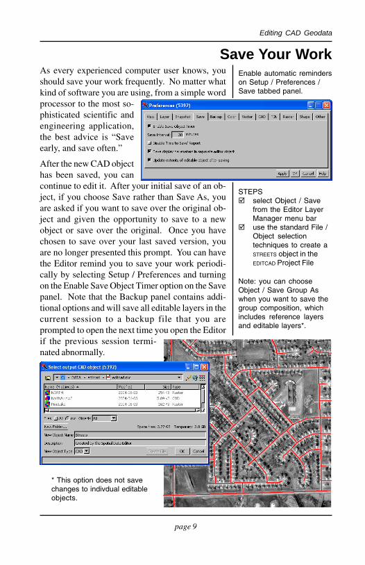
Save Your WorkEnable automatic reminderson Setup / Preferences /Save tabbed panel.
As every experienced computer user knows, youshould save your work frequently. No matter whatkind of software you are using, from a simple wordprocessor to the most so-phisticated scientific andengineering application,the best advice is “Saveearly, and save often.”
After the new CAD objecthas been saved, you cancontinue to edit it. After your initial save of an ob-ject, if you choose Save rather than Save As, youare asked if you want to save over the original ob-ject and given the opportunity to save to a newobject or save over the original. Once you havechosen to save over your last saved version, youare no longer presented this prompt. You can havethe Editor remind you to save your work periodi-cally by selecting Setup / Preferences and turningon the Enable Save Object Timer option on the Savepanel. Note that the Backup panel contains addi-tional options and will save all editable layers in thecurrent session to a backup file that you areprompted to open the next time you open the Editorif the previous session termi-nated abnormally.
STEPS select Object / Save
from the Editor LayerManager menu bar
use the standard File /Object selectiontechniques to create aSTREETS object in theEDITCAD Project File
Note: you can chooseObject / Save Group Aswhen you want to save thegroup composition, whichincludes reference layersand editable layers*.
* This option does not savechanges to indivdual editableobjects.
page 10
Editing CAD Geodata
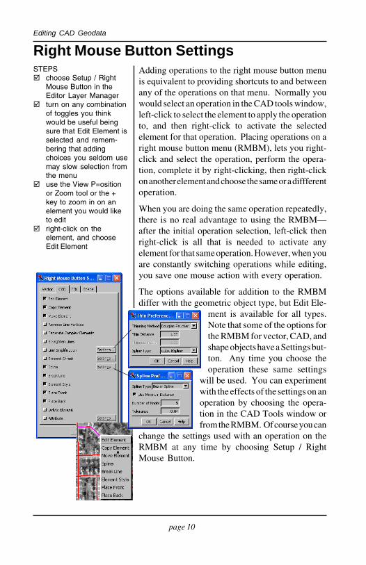
Right Mouse Button SettingsSTEPS choose Setup / Right
Mouse Button in theEditor Layer Manager
turn on any combinationof toggles you thinkwould be useful beingsure that Edit Element isselected and remem-bering that addingchoices you seldom usemay slow selection fromthe menu
use the View P=ositionor Zoom tool or the +key to zoom in on anelement you would liketo edit
right-click on theelement, and chooseEdit Element
Adding operations to the right mouse button menuis equivalent to providing shortcuts to and betweenany of the operations on that menu. Normally youwould select an operation in the CAD tools window,left-click to select the element to apply the operationto, and then right-click to activate the selectedelement for that operation. Placing operations on aright mouse button menu (RMBM), lets you right-click and select the operation, perform the opera-tion, complete it by right-clicking, then right-clickon another element and choose the same or a diffferentoperation.
When you are doing the same operation repeatedly,there is no real advantage to using the RMBM—after the initial operation selection, left-click thenright-click is all that is needed to activate anyelement for that same operation. However, when youare constantly switching operations while editing,you save one mouse action with every operation.
The options available for addition to the RMBMdiffer with the geometric object type, but Edit Ele-
ment is available for all types.Note that some of the options forthe RMBM for vector, CAD, andshape objects have a Settings but-ton. Any time you choose theoperation these same settings
will be used. You can experimentwith the effects of the settings on anoperation by choosing the opera-tion in the CAD Tools window orfrom the RMBM. Of course you can
change the settings used with an operation on theRMBM at any time by choosing Setup / RightMouse Button.
page 11
Editing CAD Geodata
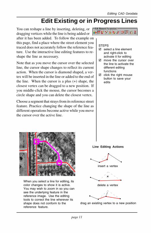
Edit Existing or in Progress LinesYou can reshape a line by inserting, deleting, ordragging vertices while the line is being added orafter it has been added. To follow the example onthis page, find a place where the street element youtraced does not accurately follow the reference fea-ture. Use the interactive line editing features to re-shape the line as necessary.
Note that as you move the cursor over the selectedline, the cursor shape changes to reflect its currentaction. When the cursor is diamond shaped, a ver-tex will be inserted in the line or added to the end ofthe line. When the cursor is a plus (+) shape, theclosest vertex can be dragged to a new position. Ifyou middle-click the mouse, the cursor becomes acircle shape and you can delete the closest vertex.
Choose a segment that strays from its reference streetfeature. Practice changing the shape of the line asdifferent operations become active while you movethe cursor over the active line.
When you select a line for editing, itscolor changes to show it is active.You may wish to zoom in so you cansee the underlying feature in thereference image. Use the editingtools to correct the line wherever itsshape does not conform to thereference feature.
STEPS select a line element
and right-click toactivate it for editing
move the cursor overthe line to activate thedifferent editingfunctions
click the right mousebutton to save youredits
Line Editing Actions
delete a vertex
drag an existing vertex to a new position
insert a vertex
page 12
Editing CAD Geodata
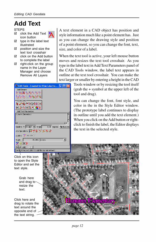
STEPS click the Add Text
icon button type in the label text
illustrated position and size the
text tool crosshair click on the Add button
to complete the label right-click on the group
name in the LayerManager and chooseRemove All Layers
Add Text
Grab hereand drag toresize thetext.
A text element in a CAD object has position andstyle information much like a point element has. Justas you can change the drawing style and positionof a point element, so you can change the font, text,size, and color of a label.
When the text tool is active, your left mouse buttonmoves and resizes the text tool crosshair. As youtype in the label text in Add Text Parameters panel ofthe CAD Tools window, the label text appears inoutline at the text tool crosshair. You can make thetext larger or smaller by entering a height in the CAD
Tools window or by resizing the tool itself(grab the + symbol at the upper left of thetool and drag).
You can change the font, font style, andcolor in the in the Style Editor window.(The prototype label continues to displayin outline until you add the text element.)When you click on the Add button or right-click to finish the label, the Editor displaysthe text in the selected style.
Click here anddrag to rotate thetext around theopposite end ofthe text string.
Click on this iconto open the StyleEditor and set thetext style.
page 13
Editing CAD Geodata
Geometric Shapes
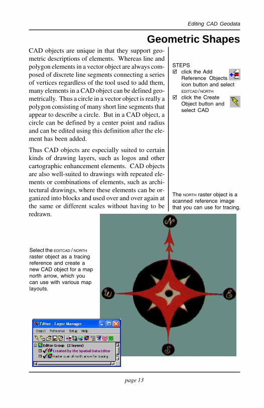
The NORTH raster object is ascanned reference imagethat you can use for tracing.
Select the EDITCAD / NORTH
raster object as a tracingreference and create anew CAD object for a mapnorth arrow, which youcan use with various maplayouts.
STEPS click the Add
Reference Objectsicon button and selectEDITCAD / NORTH
click the CreateObject button andselect CAD
CAD objects are unique in that they support geo-metric descriptions of elements. Whereas line andpolygon elements in a vector object are always com-posed of discrete line segments connecting a seriesof vertices regardless of the tool used to add them,many elements in a CAD object can be defined geo-metrically. Thus a circle in a vector object is really apolygon consisting of many short line segments thatappear to describe a circle. But in a CAD object, acircle can be defined by a center point and radiusand can be edited using this definition after the ele-ment has been added.
Thus CAD objects are especially suited to certainkinds of drawing layers, such as logos and othercartographic enhancement elements. CAD objectsare also well-suited to drawings with repeated ele-ments or combinations of elements, such as archi-tectural drawings, where these elements can be or-ganized into blocks and used over and over again atthe same or different scales without having to beredrawn.
page 14
Editing CAD Geodata
Draw reference lines thatintersect in the middle of thegraphic, and then add the smallcenter circle. Nudge theprototype circle with the arrowkeys on the keyboard.
STEPS select the Add
Circle tool anddraw the small circle inthe middle
select the Add Linetool and draw N-Sand E-W referenceaxes
if you have difficultiesdrawing a straightline, click on theManual Entry iconand change the Xcoordinate for one endof the vertical line andthe Y coordinate for oneend of the horizontal lineto match the other end
use the arrow keys tonudge the circle’scenter to the intersec-tion of the referenceaxes
when the circle is sizedand positioned cor-rectly, right-click toaccept it
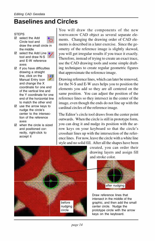
Baselines and CirclesYou will draw the components of the newNORTHARROW CAD object as several separate ele-ments. Changing the drawing order of CAD ele-ments is described in a later exercise. Since the ge-ometry of the reference image is slightly skewed,you will get irregular results if you trace it exactly.Therefore, instead of trying to create an exact trace,use the CAD drawing tools and some simple draft-ing techniques to create regular geometric figuresthat approximate the reference image.
Drawing reference lines, which can later be removed,for the N-S and E-W axes helps you to position theelements you add so they are all centered on thesame position. You can adjust the position of thereference lines so they intersect in the center of theimage, even though the ends do not line up with thecardinal circles of the reference image.
The Editor’s circle tool draws from the center pointoutwards. When the circle is still in prototype form,you can drag it and nudge its position with the ar-row keys on your keyboard so that the circle’scrosshair lines up with the intersection of the refer-ence lines. For now, leave the circle with a white linestyle and no solid fill. After all the shapes have been
created, you can order theirdrawing layers and assign filland stroke color.
beforenudgingcircle
after nudging

page 15
Editing CAD Geodata
The diamond and arrow shapes of the reference im-age could be created in several ways. The CADeditor offers a number of flexible shape drawing tools.For example, the four triangular areas that extendbeyond the pinwheel diamond shapes could bedrawn individually with the Add Regular Polygontool or as a single or separate polygons with thefreeform polygon tool.
Select the polygon tool and trace the pinwheel dia-mond at the center. Put enough vertices along theoutline to represent the curved edge. Since the shapeis irregular with respect to your reference axes, de-cide how you want to treat the irregularity. In theillustration, the point at each tip of the shape touchesa reference line, and the curve pulls back slightlybefore crossing the line on its way to the next tip.Draw the polygon and then adjust/add vertices forsymmetry and balance.
When you are satisfied with the small pinwheel, usethe polygon tool to draw the larger pinwheel and thelarge red star and its double arrow. Use the circletool for the large black circle, and each of the cardi-nal circles. Use the text tool for the N, S, E, and Wtext labels with a font similar to the one in the refer-ence image or any TrueType fontyou have.
In order to provide balance andsymmetry, you may wish to addtemporary lines, rectangles,circles, and other shapes foralignment and proportion. Feelfree to depart from the referenceimage, and experiment with thechord, arc, and wedge shapes tocreate designs of your own.
Drawing Other Shapes
STEPS select the Add
Polygon tool andtrace the small, central,pinwheel
refine the fit of thepolygon according tothe techniquesdescribed on page 11
add polygons, circles,and text for each of theother components
Remember to Object / Saveyour work. Give the newCAD object a name likeNORTHARROW and put it in theEDITCAD or a new ProjectFile.
Use the polygon tool totrace the pinwheel shape inthe middle of the image.
Note: when adding thecircles at the cardinalpoints, you may want toturn off the Clear Tool AfterAdd toggle on the CADtabbed panel of the Setup/Preferences window toeasily create four samesize circles that simplyneed to be repositioned notredrawn.
page 16
Editing CAD Geodata
After you have created each of the graphic elements,it remains to set their drawing style, in this case fillcolor, and set the drawing order of the elements.You could have set the drawing style as each ele-ment was added. Elements could also be createdwith the correct drawing order, but that takes con-siderable forethought. Elements created first are be-neath, or behind, those created later.
Because CAD elements may overlap, it is sometimesdifficult to select the element you want. If you havedifficulty selecting the element you want to style,right-click on the CAD elements icon in the LayerManager, and chooseMark All from themenu. Then use theNext Marked and Previous Marked iconpair on the View window toolbar to stepthrough the marked elements until the one you wantis shown in the active color. Once the desired ele-ment is highlighted, right-click to activate it for edit-ing. You can use the same procedure to select CADelements for any operation.
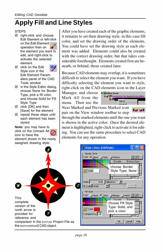
Apply Fill and Line StylesSTEPS right-click and choose
Edit Element or left-clickon the Edit Elementoperation then onthe element you want toedit, and right-click toactivate the selectedelement
click on the EditStyle icon in theEdit Element Param-eters panel of the CADTools window
in the Style Editor dialog,choose None for BorderType, pick a fill color,and choose Solid for FillStyle Type
click [OK] and then[Save] for the element
repeat these steps untileach element has beenstyled
Thiscompleteversion of thenorth arrow isprovided forreference andcomparison in the EDITCAD Project File asthe NORTHARROW2 CAD object.
choose Fill StyleType: Solid, andpick a color
choose BorderStyle Type: None
Note: you may have toclick on the Unmark Allicon to have theelement shown in the newlyassigned drawing style.
page 17
Editing CAD Geodata
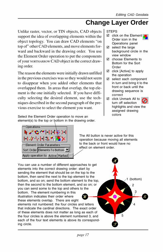
Select the Element Order operation to move anelement(s) to the top or bottom in the drawing order.
Change Layer OrderUnlike raster, vector, or TIN objects, CAD objectssupport the idea of overlapping elements within theobject topology. You can draw CAD elements “ontop of” other CAD elements, and move elements for-ward and backward in the drawing order. You usethe Element Order operation to put the componentsof your NORTHARROW CAD object in the correct draw-ing order.
The reason the elements were initially drawn unfilledin the previous exercises was so they would not seemto disappear when you added other elements thatoverlapped them. In areas that overlap, the top ele-ment is the one initially selected. If you have diffi-culty selecting the desired element, use the tech-niques described in the second paragraph of the pre-vious exercise to select the element you want.
STEPS click on the Element
Order icon in theOperations panel
select the largebackground circle in theview window
choose Elements toBottom for the SortOrder
click [Active] to applythe operation
select each componentin turn and bring it to thefront or back until thedrawing sequence iscorrect
click Unmark All toturn off selectionhighlights and view theassigned drawingcolors
You can use a number of different approaches to getelements into the correct drawing order: start bysending the element that should be on the top to thebottom, then send the next to the top element to thebottom, and so on; send the bottom element to the top,then the second to the bottom element, and so on; oryou can send some to the top and others to thebottom. The element numbering in thisillustration indicates their order wherethese elements overlap. There are eightelements not numbered: the four circles and lettersthat indicate the cardinal directions. The exact orderof these elements does not matter as long as each ofthe four circles is above the element numbered 3, andeach of the four text elements is above its correspond-ing circle.
1 (bottom)
2
3
4
5
The All button is never active for thisoperation because moving all elementsto the back or front would have noeffect on element order.
page 18
Editing CAD Geodata
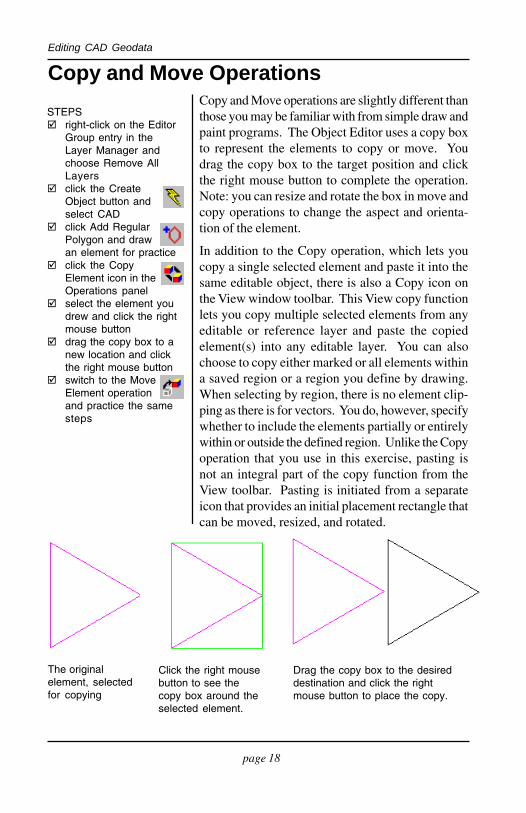
Copy and Move Operations
Drag the copy box to the desireddestination and click the rightmouse button to place the copy.
STEPS right-click on the Editor
Group entry in theLayer Manager andchoose Remove AllLayers
click the CreateObject button andselect CAD
click Add RegularPolygon and drawan element for practice
click the CopyElement icon in theOperations panel
select the element youdrew and click the rightmouse button
drag the copy box to anew location and clickthe right mouse button
switch to the MoveElement operationand practice the samesteps
The originalelement, selectedfor copying
Click the right mousebutton to see thecopy box around theselected element.
Copy and Move operations are slightly different thanthose you may be familiar with from simple draw andpaint programs. The Object Editor uses a copy boxto represent the elements to copy or move. Youdrag the copy box to the target position and clickthe right mouse button to complete the operation.Note: you can resize and rotate the box in move andcopy operations to change the aspect and orienta-tion of the element.
In addition to the Copy operation, which lets youcopy a single selected element and paste it into thesame editable object, there is also a Copy icon onthe View window toolbar. This View copy functionlets you copy multiple selected elements from anyeditable or reference layer and paste the copiedelement(s) into any editable layer. You can alsochoose to copy either marked or all elements withina saved region or a region you define by drawing.When selecting by region, there is no element clip-ping as there is for vectors. You do, however, specifywhether to include the elements partially or entirelywithin or outside the defined region. Unlike the Copyoperation that you use in this exercise, pasting isnot an integral part of the copy function from theView toolbar. Pasting is initiated from a separateicon that provides an initial placement rectangle thatcan be moved, resized, and rotated.

page 19
Editing CAD Geodata
Working With BlocksTNT’s Editor supports the block data structure inCAD objects. A block is a “super element” com-posed of one or more individual elements. For ex-ample, the NORTHARROW2 block on this page is com-posed of several polygon, text, and circle elements.Once you have created a block, you can use it againand again without recreating it each time. Blocks areefficient data elements, since the block definition isrecorded only once and that definition is referencedfor each instance of that block. The only editingoperations you can perform on a block are to move,resize, and rotate it.
To create a block, create a new CAD object, com-pose the block with the elements you want, and savethe object. For example, the NORTHARROW2 block onthis page was created and saved in the exercises onpages 13-17 of this booklet.
Complex relations canbe defined to associateCAD elements withdatabase tables. Refer tothe tutorials Editing VectorGeodata and ManagingRelational Databases formore information.
The Editorprovides Arc,Arc Chord, and Arc Wedgetools. They work just likethe circle and rectangletools: you drag out aprototype shape, adjust itssize and position, and clickthe right mouse button toplace it.
The CoordinateGeometry (COGO)process includes COGOfunctions used inprofessional surveyingand civil engineeringapplications.
Where Next?
The NORTHARROW2 CADobject can be inserted as ablock, which is resized androtated as a unit.
...
Right-click on a CADlayer and choose Edit BlockInformation to select saved CAD objects to act asblocks in the object you are editing. After you haveadded one or more blocks to this list, the Add BlockInsert tool is active in the CAD Tools window.
All blocks currently available forinsertion are listed in the Add BlockParameters panel. The RowColumn Controls icon lets youinsert multiple instances of a blockas a single block element. The
block is repeated in thenumber of rows andcolumns you designateif you use this feature.The spacing betweenrows and columns canbe set independently.

page 20
Editing CAD GeodataAdvanced Software for Geospatial Analysis EDIT
CAD
www.microimages.com
MicroImages, Inc. publishes a complete line of professional software for advanced geospatial datavisualization, analysis, and publishing. Contact us or visit our web site for detailed productinformation.
TNTmips Pro TNTmips Pro is a professional system for fully integrated GIS, imageanalysis, CAD, TIN, desktop cartography, and geospatial database management.
TNTmips Basic TNTmips Basic is a low-cost version of TNTmips for small projects.
TNTmips Free TNTmips Free is a free version of TNTmips for students and profession-als with small projects. You can download TNTmips Free from MicroImages’ web site.
TNTedit TNTedit provides interactive tools to create, georeference, and edit vector, image,CAD, TIN, and relational database project materials in a wide variety of formats.
TNTview TNTview has the same powerful display features as TNTmips and is perfect forthose who do not need the technical processing and preparation features of TNTmips.
TNTatlas TNTatlas lets you publish and distribute your spatial project materials on CD orDVD at low cost. TNTatlas CDs/DVDs can be used on any popular computing platform.
Indexactive elements ........................................ 1 1add block tool ......................................... 1 9Add Circle tool ....................................... 14add line elements ...................................... 8Add Line tool ..................................... 6, 14Add Polygon tool ................................... 15Add Text tool .......................................... 12arc, arc chord, arc wedge tools ............. 19automatic save reminder .......................... 9baselines and circles ............................... 14blocks ....................................................... 1 9CAD tools .................................................. 6clear button ............................................... 8COGO ...................................................... 19Copy operation ....................................... 18create new object ...................................... 5Edit Elements ..................................... 6, 10Edit Style tool ......................................... 16Edit Style ................................................... 6editable layers .................................... 3, 18Element Order tool ................................. 17
geometric shapes .................................... 13insert, delete, drag line vertices ............ 1 1labels ........................................................ 12layer order ............................................... 17Line/Polygon Edit Controls .................... 6Move operation ...................................... 18New Object Values dialog ....................... 5pan and zoom ........................................... 8prototype line ............................................ 7reference layers .................................... 3, 4reference lines ......................................... 14right mouse button menu (RMBM) ..... 1 0sample data ................................................ 2Save Object Timer .................................... 9save your work ......................................... 9selecting elements ................................... 10stretch mode .............................................. 6Style Editor dialog ................................. 16Text Label Edit Controls ....................... 1 2text styles ................................................. 12text tool ............................................. 12, 15
MicroImages, Inc.¤