editing graphical objects using procedural representations · graphics programming languages. this...
TRANSCRIPT
AbstractTraditionally, people have created computer-generated images by writing programs in a pro
gramming language that supports graphics. More recently, interactive graphics editors have become commonplace. Graphics editors are easy to use but lack many of the capabilities found ingraphics programming languages. This deficiency is intrinsic to graphics editors; it is not aresult of neglect or incompetence by the implementer.
Tweedle is a graphics editor that attempts to bridge this gap by using a program as its internalrepresentation for a picture. During an editing session the user can modify either the pictureitself or the program representation; the editor modifies the other to keep the two consistent. Thelanguage used by the editor contains features that allow the editor to incrementally execute partsofa program in response to a change so that the picture can be regenerated without completelyreexecuting the program.
The use of a procedural representation allows the user to create pictures with structure, repetition, recursion, and calculated point values. It further allows him to define parts of a drawing asvariants of other parts; these variants can differ from their original objects in quite arbitrary waysbut still respond to changes made to the original. The language supports linking different partsof the picture together to maintain connections between parts as the picture changes.
A working prototype of Tweedle has been implemented under the X Window System.
This document is a revised version of my Ph.D. thesis at Stanford University. The researchwas supported in part by a faculty matching grant from Digital Equipment Corporation to Prof.Brian Reid, and in part by other resources provided to Stanford by Digital Equipment Corporation. The author was a consultant to Digital's Western Research Laboratory during the research,and acknowledges the various WRL resources made available to him during that time.
Table of Contents1. Introduction
1.1. Overview1.2. Graphics languages and graphics editors1.3. Procedural and nonprocedural representation languages1.4. What Tweedle isn't1.5. A note on the cast of characters
2. Previous Work2.1. Procedural representations in graphics systems2.2. Graphics editors
3. The Programming Language3.1. Language design goals3.2. Language overview
3.2.1. Graphics operations3.3. Object semantics3.4. Why a new language?
4. The Graphics Editor4.1. Incremental execution4.2. User interface
4.2.1. Bounding boxes4.3. Generating code4.4. An extended example
5. Implementation5.1. Overview5.2. Parsing5.3. Data representation5.4. Basic execution5.5. Paths and the display tree5.6. Objects and inheritance5.7. Display and funargs5.8. The using statement5.9. Incremental parsing5.10. Incremental execution5.11. Display and graphics editor5.12. Display optimization
5.12.1. Display coordinate caching5.12.2. Incremental bounding box calculations5.12.3. Incremental redisplay
5.13. Relative transformations5.14. Source-code optimization5.15. Libraries5.16. Generating PostScript
6. Contributions and Future Work6.1. Contributions6.2. Deficiencies & future work6.3. What I would do differently
I. Syntax of the Dum LanguageII. Predefined Functions
II.I. Mathematical functionsII.2. Comparison and logical functions
11247899
1015151617193032323639414454545456565858596262636464656566677072727474757680848484

II.3. Point manipulation functionsII.4. Transformation functionsII.5. Array manipulation functionsII.6. String functionsII.7. Paint functionsII.8. Object functions
ii
858586868686
1. IntroductionPeople have used computers to create pictures nearly as long as computers have existed.
These pictures range from crude character graphics on a line printer to the sophisticated output oftoday's laser printers. Traditionally, people created these pictures by writing a program in somecomputer language that supported graphics, usually through some kind of subroutine library. Interactive drawing programs, or graphics editors, are an alternate way of creating pictures, and inthe past decade these editors have gone from being an interesting novelty to an accepted part ofcomputer systems. Each approach has advantages and disadvantages, and in many cases theseare complementary: the disadvantages of programs are the advantages of editors, and the disadvantages of editors are the advantages of programs.
My goal is to integrate these two approaches by creating a graphics editor that uses a programas the underlying representation for a picture. This allows a user to use the editor to interactivelycreate pictures while still having the capability to fall back upon programming when necessary.
1.1. OverviewTweedle is a system that combines a graphics editor, Dee, with a programming language,
Dum. Any graphics editor must use some kind of data representation to store the picture internally during execution and externally between executions; in Dee this representation is aprogram written in the Dum language. Executing the program produces the picture.
Dee presents the user with two windows, one containing a picture to be edited and the othercontaining the text of the program that represents the picture. The user can change the picture byselecting parts of it with a mouse and issuing commands through menus, or can change the textusing a standard text editing interface. Changes to the picture are reflected immediately by corresponding changes to the program so that the modified program will produce the modified picture; changes to the text take place in the picture when a Do Changes operation is selected.
Tweedle contains several innovative ideas. Most important, it extends procedural representations into the domain of interactive programs. Up to now, procedural representations havebeen batch oriented; programs that used them manipulated them as a whole. In Tweedle, therepresentation is constantly changing in response to user input, and acceptable interactiveresponse precludes fully reexecuting the representation in response to every change. Tweedle'sinterpreter is able to incrementally execute changed representations, executing only a subset ofthe program but producing the same results as if the program had been fully reexecuted. Theinterpreter automatically determines how much of the program is affected by a program change;in order to make this work well, Dum was designed to allow this determination be done througha static structural analysis of the program.
Dum programs are structured by defining and calling drawing procedures that create subpartsof a picture. These subparts, called objects, can later be manipulated by the program in order tochange the picture. Dum thus combines the simplicity of the drawing procedure approach withthe flexibility of the segment approach to graphics languages.
The procedural representation facilitates a variation hierarchy of graphical objects. Thishierarchy allows a user to define a new object as a variant of an existing object by describing theprocedure used to change the original object into the variant. Any later changes to the original
2
object will also affect the variant. Variant objects make it easy for a user to create differentobjects with a similar style and to keep these objects consistent should the style change.
Objects in Dum can define control points that other object can use for positioning. Controlpoints can allow arrows to connect to boxes, captions to be centered under pictures, or, sincecontrol points are gravity active in the editor, objects to line up on a grid. The interpreter ensuresthat whenever an object is changed that all parts of the program that depend upon the values ofthe object's control points are properly reexecuted so that the positioning relationships continueto hold.
1.2. Graphics languages and graphics editorsGraphics editors are one type of "what you see is what you get", or WYSIWYG, program. The
picture on the screen directly reflects the picture in the final output, and changes to the picturetake place as soon as they are specified by the user. These editors are easy to use and quitesufficient for many pictures; however, they have some limitations. Because the editor is constrained to show exactly the current picture, structuring information is either invisible to the useror simply not present at all. Frequently different parts of the picture should bear some spatialrelationship to each other, and unless these relations are explicitly described somewhere they arelikely not to hold as the parts of the picture are moved around. Some pictures require points withexact or computed values, and these are difficult to create with an editor. Other pictures are mosteasily expressed using iteration or recursion, facilities absent in graphics editors.
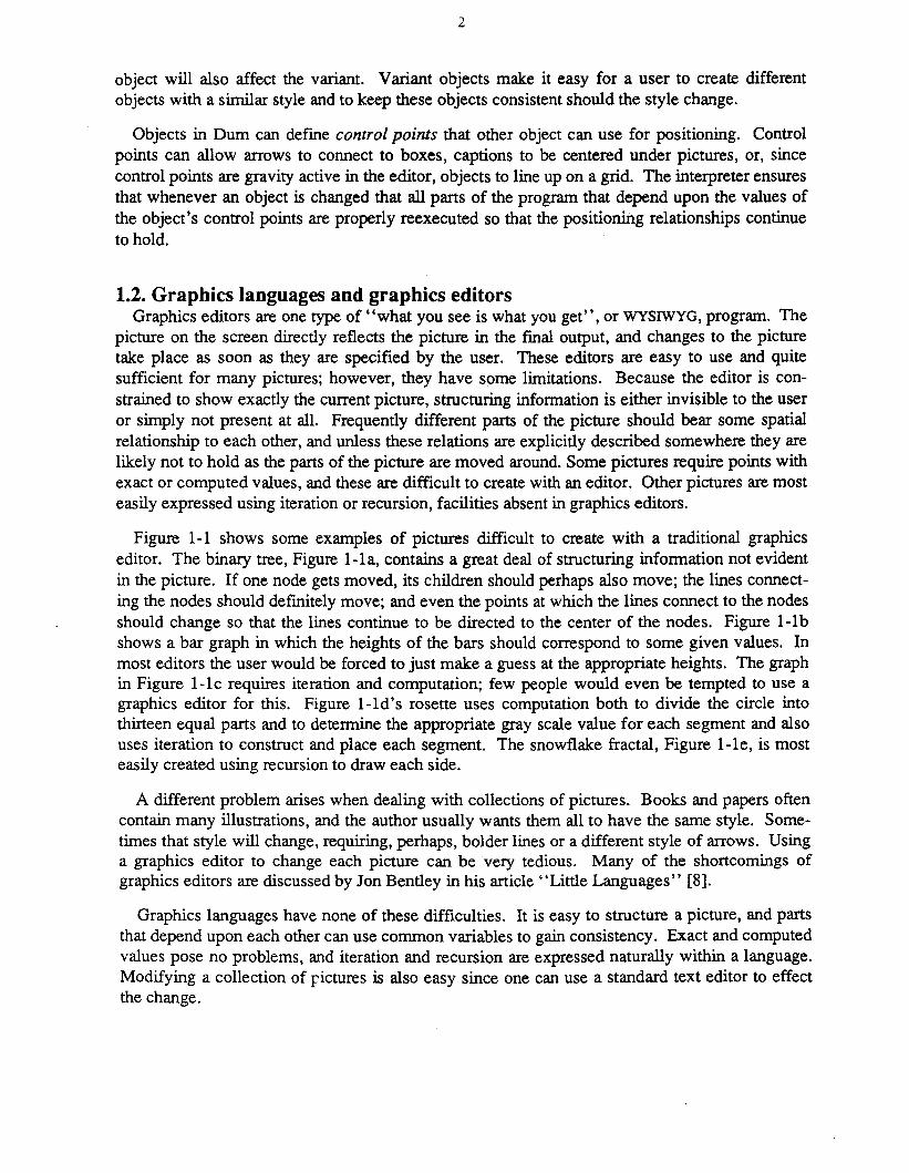
Figure 1-1 shows some examples of pictures difficult to create with a traditional graphicseditor. The binary tree, Figure 1-1a, contains a great deal of structuring information not evidentin the picture. If one node gets moved, its children should perhaps also move; the lines connecting the nodes should defmitely move; and even the points at which the lines connect to the nodesshould change so that the lines continue to be directed to the center of the nodes. Figure I-Ibshows a bar graph in which the heights of the bars should correspond to some given values. Inmost editors the user would be forced to just make a guess at the appropriate heights. The graphin Figure I-Ie requires iteration and computation; few people would even be tempted to use agraphics editor for this. Figure I-Id's rosette uses computation both to divide the circle intothirteen equal parts and to determine the appropriate gray scale value for each segment and alsouses iteration to construct and place each segment. The snowflake fractal, Figure I-Ie, is mosteasily created using recursion to draw each side.
A different problem arises when dealing with collections of pictures. Books and papers oftencontain many illustrations, and the author usually wants them all to have the same style. Sometimes that style will change, requiring, perhaps, bolder lines or a different style of arrows. Usinga graphics editor to change each picture can be very tedious. Many of the shortcomings ofgraphics editors are discussed by Jon Bentley in his article "Little Languages" [8].
Graphics languages have none of these difficulties. It is easy to structure a picture, and partsthat depend upon each other can use common variables to gain consistency. Exact and computedvalues pose no problems, and iteration and recursion are expressed naturally within a language.Modifying a collection of pictures is also easy since one can use a standard text editor to effectthe change.

(a)
3
(b)
(c)
(d) (e)
Figure I-I: Pictures difficult to draw with a graphics editor
4
Languages are not, however, without their own problems. The overhead involved in writingeven a simple program can be daunting. Interactive behavior must be specifically coded intoeach program; without it getting the desired output can be a tedious repetitive cycle of editing,compiling, running, and looking at the output. The flip side of allowing exact point values isrequiring them, even when the programmer has only a vague idea of what they might be.
These problems most often show up in positioning. It is easy to write a program that draws atree, but difficult to place the nodes for a pleasing result without interactive feedback. Drawing agraph or plot is easy; finding the best place for titles and legends is not. Freehand drawing andlayout require user interaction to prevent total frustration.
Tweedle combines the ease of use of a graphics editor with the completeness and extensibilityof a graphics language; the limitations of graphics editors are overcome by giving the user thefull power of a language for writing extensions, structuring pictures, and specifying exact orcomputed values. The editor can manipulate user-defined objects like the five pictures in Figure1-1 as easily as it can manipulate predefined objects like lines, circles, and rectangles. Both arerepresented as procedures that use low-level graphics primitives to do drawing; the only difference is that the defmitions of predefmed objects are implicitly included in each drawing.Users can store their own objects in libraries and thereby make them available to multiple drawings, so it is easy to maintain consistency across drawings.
Of course Tweedle does not require its user to use the language to define new objects; in manycases the new objects can be created within the editor by combining already existing objects.Most of the time the user can use the editor without caring that his picture is represented as aprogram, but when he encounters the limits of the editor he can edit the program representationinstead. A given picture can combine objects created by the graphics editor and objects createdby the text editor indiscriminately.
1.3. Procedural and nonprocedural representation languagesComputers rarely operate upon real world entities; instead they manipulate representations of
these entities. A representation is a well-defined data structure that maps properties of these realentities to computer-operable information. A language is a set of rules that defines which datastructures form valid representations. The distinction between languages and representations islargely artificial, and which term is used frequently depends upon the scale of the problem.When the rules describing the data structure are simple, as with a binary tree representing asorted list, one usually focuses on the data structure itself and calls it a representation. When therules are complex, as with a stream of characters representing an algorithm, one focuses on therules instead and calls it a language.
In some cases a data structure is complex enough to be called a language, but so clearlydescribes a real world object that "representation" still seems appropriate. Languages in thisclass are often called, logically enough, representation languages; examples include theknowledge representation languages used in expert systems, document description languages,and page description languages. These representation languages fall into two classes:nonprocedura/languages, which describe the desired end result but not how to achieve it, andprocedural languages, which describe the end result by describing how to achieve it. Nonprocedural languages are also sometimes called descriptive, declarative, or very high /eve/languages.
5
Arguments about whether procedural or nonprocedural languages are most appropriate for aproblem have been going on for quite some time [22]. Nonprocedural languages allow theprogram writer to concentrate upon the end result without worrying about implementationdetails. This makes them easier to use, especially for nonprogrammers. Conversely, the language implementor is free to use whatever means are most appropriate to a particular implementation to achieve these results.
The most severe limitation of declarative languages is that they do not extend gracefully. Aslong as the user is trying to describe the kinds of things the designer envisioned when he createdthe language, there are no problems, but as soon as he tries to do anything else he finds himselfin trouble. If the language cannot describe it, the user cannot write it; this is sometimes called"running into the edges of the representation." Some nonprocedural languages solve this byallowing extensions to the language, but the language used for the extensions is usually quitedifferent from the original language.
Procedural languages can solve the extensibility problem by having low level primitives andcontrol structures for combining them; however, these primitive operations can make it easy forthe user of such a language to become enmeshed in a web of details irrelevant to the problem heis trying to solve. Most procedural representation languages have facilities for defming macrosor procedures that represent high level constructs; programs that uses these are often indistinguishable from descriptive programs. Procedural languages can thus masquerade as declarativeones, but not vice-versa.
Procedurality, it must be noted, does not automatically guarantee extensibility. Commandstream languages consist of a series of operations and are thus procedural, but they do not havethe ability to compose these operations in an extendible way. Early text formatting programsprovide a good example of this. In order to format an indented quotation, a user would writesomething equivalent to
Skip a lineSet left margin to 2 inchesSet right margin to 6.5 inchesFormat the text "This is the body of the quotation"Set left margin to 1 inch .Set right margin to 7.5 inchesSkip a line
(The "Fonnat the text ..... command would normally be implicit). Page description languagescan be similar: "Move to (500,654). Switch to italics. Print an 'A.' " Extensible procedurallanguages contain commands similar to these in order to actually produce results, but they allowthe commands to be grouped into subroutines, used in conditionals and loops, and take calculated values as arguments. [34] I will hereafter use "procedural" to refer only to languageswith these properties, and "command" to refer to procedural languages without them.
Of course there is a continuum between purely procedural and purely descriptive languages;even languages like Pascal or C that initially appear totally procedural contain descriptive elements in the form of variable declarations. Nonetheless, most languages fall readily into oneclass or the other. Concrete comparisons between the two styles are difficult to make since thereare so few applications for which there are both declarative and procedural representations. Theidea of using a procedural representation for something besides a procedure has only recentlystarted to become popular; the reverse, using a declarative language to represent a procedure, iseven more rare. Document description is one area that has substantial examples on each side.
6
Scribe [30,31,32] is a document description language that is almost entirely declarative. Thebulk of an input file consists of sections of text enclosed in environments that describe the function or appearance of the text they enclose. Typical functional environments are quotations,footnotes, subscripts, and enumerated lists; appearance environments can indicate centering,italics, and so forth. Scribe also contains a few procedural constructs like starting a new page orsetting tab stops.
TEX [17,18] and troff [28] are procedural document description languages. They containcommands to do things like change margins, skip vertical space, and change type faces, and alsocontain commands that manipulate esoteric things like registers, parameters, marks, insertions,diversions, and traps. Neither raw TEX nor raw troff is a particularly hospitable environment foranyone but the most dedicated hacker; fortunately both provide macro facilities that allow themessy details to be hidden from the casual user.
LATEX [20] is a popular macro package for TEX. A document written using U\TEX doesn'tlook much different from one written using Scribe; for example, in U\TEX one writes a quotationlike
\begin{quotation}This is an uninteresting quote.\end{quotation}
while in Scribe one writes@begin(quotation)And this one isn't much better.@end(quotation)
The actions taken by the document compiler are, however, very different in each case. In U\TEXthe \begin {quotation} and the \end{quotation} get expanded as macros into seriesof low-level TEX commands; these commands skip the appropriate space above and below andchange the margins. In Scribe, @begin (quotation) causes a database lookup to find theattributes of the quotation environment. This lookup tells the compiler that the quotation'stext should be offset with vertical space above and below and should have narrower margins.The difference is subtle but important. The definition of a U\TEX macro can contain arbitrarilycomplicated TEX commands such as conditional expressions, mathematical computations, orrecursive macro calls. The definition of a Scribe environment, on the other hand, gives the settings of predefined text parameters. A TEX user can produce novel layout effects by includingnew macro definitions in his input file; in Scribe these could only be produced by modifying thecompiler to add new features.
This distinction is intrinsic to representation languages for any sufficiently complex system.There will always be things that require computation to represent cleanly, and any language thatincludes computation is, by definition, procedural. Any particular feature can be added to adeclarative language by extending the language definition, of course, but before long the language starts to lose any coherence it originally had. Descriptive languages excel at well-defined,closed tasks, while procedural languages are needed when the job is open-ended.
All of which returns us to Tweedle. Tweedle's representation language, Dum, includes objectdefinitions that function analogously to macros in TEX. Objects are high level, they can bemanipulated by the editor, and there is a large set of predefined objects. Many pictures willnever need any direct Dum programming. Dum's low level graphics statements and generalpurpose programming constructs are analogous to low-level TEX commands: you can use themto build up your own objects if you need something unusual.

<
7
Figure 1-2 shows some of the flexibility gained by this approach. Each line is an instantiationof a different object. Each object definition takes two points as arguments; what it does to getfrom one point to the other varies from object to object. Computation allows the objects toslightly modify the circle, square, or dash size in order to assure that the space gets filled with anintegral number of elements.
~.a:Ca:rrx::rJ:J:X1X
------~-------I~)
••••••••••••••••••••••••••••••••••••••••••••••••••••••••••••••
Figure 1-2: Sample line styles programmable within Tweedle
1.4. What Tweedle isn'tAlthough it resembles one in some superficial ways, Tweedle is not an automatic program
ming system. The Dee editor generates Dum code in response to user operations, and, in fact,many Dum programs are completely written by the editor. But there are many programs that theeditor cannot automatically generate and many that it cannot fully understand. Things easy to doby modifying text but hard to express through a graphics editor interface are done by modifyingthe text-that's why it is there. Conversely, the claims in Section 1.2 about the transparency ofuser-written code hold only as long as the program conforms to some minimal structuring conventions. Dee happily accepts non-conforming programs and generates the right picture, but theuser will find that some kinds of editing will not work.
8
This particular implementation of Tweedle is not a production quality graphics editor; its goalwas to be demonstrative, not comprehensive. Many things have been left out, and manysimplifying assumptions have been made. The implementation is, however, quite usable: exceptfor occasional screen dumps showing Dee in operation, all the illustrations in this thesis weredrawn with Dee.
1.5. A note on the cast of charactersSome readers may have difficulty keeping Tweedle, Dee, and Dum distinct. Tweedle is the
general name for the entire system; it includes both Dee and Dum.. Dee is the graphics editor (itallows one to design pictures) and Dum is the programming language (it is passive, mute, dumb).
9
2. Previous Work
2.1. Procedural representations in graphics systemsProcedural graphics representations can be generally divided into two classes: segment-based
representations and display procedure representations. Segment-based representations includesuch popular standards as Core and GKS [37, 38]. These representations contain explicit graphical objects, usually called segments or symbols, that are identified by name and are manipulatedby predefined operations. A program first creates a segment, then adds primitive objects likelines and curves to it. When the segment is complete, the program closes it and then explicitlydraws the segment on the display. A program mayor may not be able to modify an existingsegment once it has been closed. The structure of the program that manipulates the segments isentirely independent of the structure of the picture; this makes segment-based representationswell-suited for applications that changethe picture based on user interaction.
In a display procedure representation, subparts of the picture are represented by proceduresthat draw them. The main program consists of a series of procedure calls, and when the programhas finished running, the picture is complete. Procedure-based representations are conceptuallysimple but they are poorly suited to many interactive applications since the program must bechanged and reexecuted in order to change the picture. Their big advantage is flexibility: asegment can be rotated, scaled, or otherwise transformed but otherwise always looks the same,while a procedure can alter its flow of execution to produce different results depending upon itsinput arguments, the current graphics state, or global style parameters [25].
This last feature turns out to be very important for computer flight simulation, which requiresrapid rendering of a constantly changing image. This image will typically contain many smalldistant objects and only a few large close ones. The close objects must be rendered in detail toobtain realism, and the distant objects must be rendered quickly to obtain the needed speed. Display procedures are ideal for this application since they can readily adapt their output to show a .level of detail appropriate to their size in the image.
In this environment John Gaffney and John Warnock produced the Evans and SutherlandDesign System [14]. This language combined the image model used in other Evans and Sutherland systems with a simple stack-based semantic model. Although the Design System has neverbeen described in the literature, it had an enormous impact upon later work. John Warnockmoved to Xerox PARC and together with Martin Newell created an interactive graphics systemcalled JaM [41]. JaM combined the Design System's execution model with a slightly differentgraphical model.
Several years later, work began at PARC to develop a successor to Xerox's page descriptionlanguage, Press [27]. Press was a device-independent representation that had been implementedon various raster printers and achieved widespread use in the academic community; however, ithad a very limited set of graphical capabilities. JaM became the base for this successor,Interpress [42]. During this time Chuck Geschke and John Warnock left PARC to form AdobeSystems and there they designed the PostScript language [1], also based upon JaM.!.
IThis history is given in gloriously gorydetailby Brian Reid in a famous ARPANET Laser-Lovers message [33]
10
These languages are all more similar than they are different. Each is a stack oriented tokenbased language; a program consists of a series of operands to push upon the execution stack andoperators that act upon them. Certain operators allow the definition of new operators whileothers provide graphic operations, arithmetic functions, control structures, and so forth.Programs in these languages structure their pictures by defining and calling drawing procedures.
Special purpose graphics languages are designed to represent a particular class of drawings.Most of these are too limited in scope to be interesting, but one, PIC, provides an interesting mixof descriptive and procedural operations [15, 16]. PIC addresses itself to the boxes-and-arrowsillustrations so common to technical writing. It contains primitive operations like box, circle,ellipse, and arrow. A typical PIC program consists of a series of invocations of these operators:
ellipse "PIC" "source"arrowbox "PIC"arrowellipse "TROFF" "code"
This would produce a picture similar to Figure 2-1. The PIC interpreter takes care of the spacingbetween boxes, the positioning of labels, and other similarly menial tasks. Its defaults can beoverridden by supplying extra arguments to the operators, and the interpreter accepts argumentsin a wide variety of syntaxes, for example
arrow right from 1/3 of the way between last box.ne and last box.se
The ".ne" and ".se" in this example function similarly to control points in Tweedle but arerestricted to a small set of predefined values. In addition to high level operations like "box" and"ellipse," PIC supplies a full set of procedural operations like for and if. A user can definemacros, but these are treated quite differently from the built-in operations. PIC is very good atboxes-and-arrows pictures but can be difficult to use in other situations.
@source ~ PIC @code
Figure 2-1: PIC sample output
2.2. Graphics editorsI define an editor as a program that allows a person to interactively edit the representation of
some object. A useful distinction can be drawn between internal and external representations:an internal representation is how the editor stores the object while working on it, and an externalrepresentation is how the editor stores the object between executions. Most editors use externalrepresentations that are just versions of the internal representation capable of being stored on afile system; unless otherwise mentioned this is true of all editors discussed here.
Particularly interesting are editors that constantly present the user with an image of the currentstate of the object being edited; these are called "what you see is what you get", or WYSIWYG
editors.e There are three main classes of WYSIWYG editors, each requiring successively moreabstract representations: text editors, document editors, and graphics editors.
2Some people use a more restrictive definition of WYSIWYG, reserving it for editors that use a pointing device.
11
WYSIWYG text editors are sometimes just called screen editors. Typical of these are thevarious implementations of Emacs [39, 13]. The representation being manipulated in text editorsis really just the text me itself.
Document editors provide the same type of formatting as the document description languagesdiscussed in the last chapter. A section of the current document is displayed upon the screen andthe user manipulates it by chosing sections of text and altering such attributes as font, size, margins, and line spacing. Bravo [21] was one of the earliest examples of a document editor. It wasactually "what you see is almost what you get" since the screen size and available resolutionprecluded showing a full page's width of characters: a document's line breaks on the screenoccurred at different places from those in the printed output. Document editors are now commonplace, a typical example being MacWrite [4]. Their representation for the document isgenerally some form of command language with corrunands to change the text attributes interspersed with the text of the document. '
Since it is impossible to store a picture as such in a computer, a graphics editor's representation must be more abstract than the others'. Some graphics editors, often called paintprograms, use bitmaps as representations; among these are Markup [26], a pioneering effort, andMacPaint [3]. Bitmaps have three main disadvantages as representations, size, nonportability,and lack of structure. A bitmap representation's size is proportional to the size and not the complexity of the image; this is an advantage only for very small or extremely complicated images.Bitmap images cannot take advantage of the improved resolution of most printers; lines, curves,and letters will be printed at the screen resolution rather than the printer resolution. Bitmaps arealso very difficult to scale by other than an integral amount and to rotate by other than multiplesof ninety degrees. The general transformation algorithms are slow and the results are usuallydisappointing. Perhaps the most severe limitation is the lack of structure. While paint programshave commands to add lines, rectangles, or circles to the picture, once these things have beenadded they are just bits in the bitmap. It is impossible to later operate upon these objects asthemselves; the user can only manipulate the bits that make up the objects.
Most graphics editors use some sort of static hierarchical data structure to represent the picture. The image is kept as a list of picture items, each of which is either a primitive item oranother list. One of the first such editors was Draw from Xerox PARe [7]; MacDraw is apopular current example [5]. These editors frequently feature grids to help users make accuratedrawings; grids force points in the image to coincide with points in a rectangular grid. Grids canhelp in many cases, but even such a simple image as an equilateral triangle is beyond theircapabilities.
Some editors gain some additional power by using an external representation that is humanreadable. In these systems the user can use a standard text editor to achieve results that would beimpossible or tedious in the graphics editor. Bell Labs' PED [29] is one such system.
Constraints are an alternate representation that have been used in several interesting editors.In a these systems the user gains precision in his picture by placing geometric constraints uponthe points used to define it. Typical examples include constraining two points to be coincident,constraining three points to be collinear, constraining two points to be the same distance apart astwo other points, constraining two points to lie on a line parallel to the line through two otherpoints, and constraining two points to lie upon the same horizontal or vertical line. To create a
12
rectangle the user would first define four points A, B, C, and D in approximately the right positions, draw the line segments AB, BC, CD, and DA, and then place the following constraints onthe points:
AB is parallel to CDAB is the same length as CDAC is the same length as BD
(Other sets of constraints are possible.) The first constraint forces the quadrilateral ABCD to bea trapezoid, the second forces it to be a parallelogram, and the third forces it to be a rectangle bymaking the diagonals equal in length.
Constraints have many attractive features. Standard numerical analysis algorithms can beused to resolve them. They represent the types of relations common in drawings in a natural,consistent fashion. Finally the interface to constraint systems is straightforward: the user uses apointing device to select points in the picture and chooses a constraint from a menu to apply tothese points.
These advantages are countered by some serious problems. Getting the constraints right for apicture can be a difficult task roughly equivalent to trying to draw the picture using a compassand straightedge. The constraint solver satisfies the constraints by moving points in the picture;care must be taken to assure that it does not move the wrong points. Similarly, a given set ofconstraints can have many solutions. In the rectangle example, above, the constraints would besolved by any rectangle; the editor must provide some way of making sure that the solverproduces the one the user had in mind. A combinatorial explosion occurs as more and moreconstraints are added requiring mutual satisfaction, so the user must carefully structure his picture hierarchically to allow the solver to limit itself to just a few constraints at one time. Unlessthe editor allows the user to define his own constraints, some pictures will be tedious or evenimpossible to draw. Without user-definable constraints, it is usually impossible to constrain linesegments to have a particular length, angles to have particular values, or distances to have acalculated relation to each other. This makes pictures like the bar graph and equation plot inFigure 1-1 intractable. As in other declarative systems, iteration, recursion, and computation areonly awkwardly expressed.
The first constraint system was Ivan Sutherland's seminal Sketchpad [40]. Sketchpad storedconstraints as functions that return how far their arguments are from satisfying the constraint; theconstraint solver varied the arguments until all the error terms became zero. As an example, theprocedure for a constraint forcing two points to be horizontal might return the absolute value ofthe difference of the points' x coordinates. New constraints types could only be added bymodifying the editor. Although primitive by today's standards (it had, for example, no curves,and constraints were selected by flipping switches on the front panel of the computer) Sketchpadprovided nearly all the features found in graphics editors today.
Alan Borning's Thinglab [10] is actually a general simulation environment using constraintsto describe the things being modeled. A Thinglab constraint is a Smalltalk class with certainspecial properties; since Smalltalk is an interactive interpreted language the addition of new constraint types is an easy process. Thinglab constraints contain methods that the interpreter can useto try to satisfy the constraint; for example, the constraint for the midpoint relation might looklike
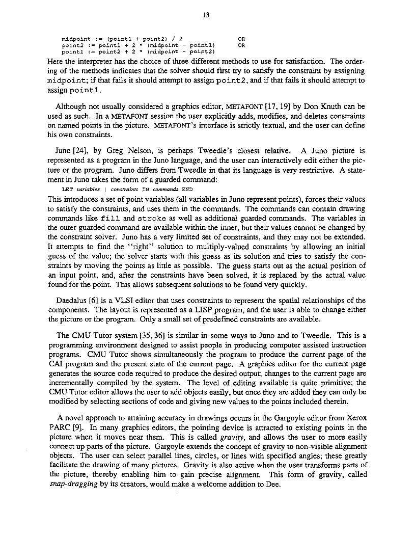
13
midpoint := (pointl + point2) / 2 ORpoint2 := pointl + 2 * (midpoint - pointl) ORpointl := point2 + 2 * (midpoint - point2)
Here the interpreter has the choice of three different methods to use for satisfaction. The ordering of the methods indicates that the solver should first try to satisfy the constraint by assigningmidpoint; if that fails it should attempt to assign point2, and if that fails it should attempt toassign pointl.
Although not usually considered a graphics editor, METAFONT [17,19] by Don Knuth can beused as such. In a METAFONT session the user explicitly adds, modifies, and deletes constraintson named points in the picture. METAFONT's interface is strictly textual, and the user can defmehis own constraints.
Juno [24], by Greg Nelson, is perhaps Tweedle's closest relative. A Juno picture isrepresented as a program in the Juno language, and the user can interactively edit either the picture or the program. Juno differs from Tweedle in that its language is very restrictive. A statement in Juno takes the form of a guarded command:
LET variables I constraints IN commands END
This introduces a set of point variables (all variables in Juno represent points), forces their valuesto satisfy the constraints, and uses them in the commands. The commands can contain drawingcommands like fill and stroke as well as additional guarded commands. The variables inthe outer guarded command are available within the inner, but their values cannot be changed bythe constraint solver. Juno has a very limited set of constraints, and they may not be extended.It attempts to find the "right" solution to multiply-valued constraints by allowing an initialguess of the value; the solver starts with this guess as its solution and tries to satisfy the constraints by moving the points as little as possible. The guess starts out as the actual position ofan input point, and, after the constraints have been solved, it is replaced by the actual valuefound for the point. This allows subsequent solutions to be found very quickly.
Daedalus [6] is a VLSI editor that uses constraints to represent the spatial relationships of thecomponents. The layout is represented as a LISP program, and the user is able to change eitherthe picture or the program. Only a small set of predefmed constraints are available.
The CMU Tutor system [35, 36] is similar in some ways to Juno and to Tweedle. This is aprogramming environment designed to assist people in producing computer assisted instructionprograms. CMU Tutor shows simultaneously the program to produce the current page of theCAl program and the present state of the current page. A graphics editor for the current pagegenerates the source code required to produce the desired output; changes to the current page areincrementally compiled by the system. The level of editing available is quite primitive; theCMU Tutor editor allows the user to add objects easily, but once they are added they can only bemodified by selecting sections of code and giving new values to the points included therein.
A novel approach to attaining accuracy in drawings occurs in the Gargoyle editor from XeroxPARC [9]. In many graphics editors, the pointing device is attracted to existing points in thepicture when it moves near them. This is called gravity, and allows the user to more easilyconnect up parts of the picture. Gargoyle extends the concept of gravity to non-visible alignmentobjects. The user can select parallel lines, circles, or lines with specified angles; these greatlyfacilitate the drawing of many pictures. Gravity is also active when the user transforms parts ofthe picture, thereby enabling him to gain precise alignment. This form of gravity, calledsnap-dragging by its creators, would make a welcome addition to Dee.
14
One final editor of interest is the Adobe Illustrator [2]. illustrator is noteworthy in that it usesa directly executable PostScript program as its. external representation. Details of its internalrepresentation are unavailable; however. there is nothing to suggest that it is other than a standard hierarchical description. A user can edit the resulting PostScript file if he desires. but hemust take care that he does not use any PostScript operators other than those in the limited setillustrator understands.
15
3. The Programming LanguageIn normal use, the Dum programming language appears to play a subordinate role to the Dee
editor. The user is creating a drawing, not writing a program, and so can, for the most part,ignore the language except in the rare occasions that he needs to edit the text. This view is acarefully cultivated illusion; the true relationship is just the opposite.
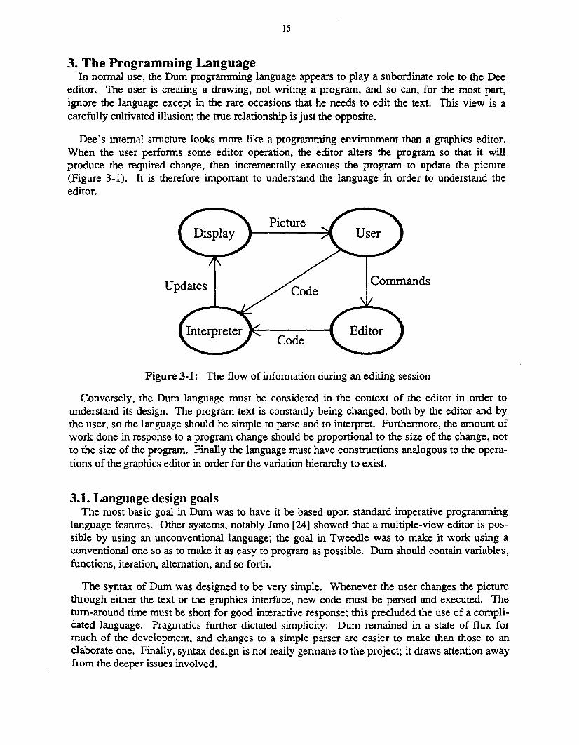
Dee's internal structure looks more like a programming environment than a graphics editor.When the user performs some editor operation, the editor alters the program so that it willproduce the required change, then incrementally executes the program to update the picture(Figure 3-1). It is therefore important to understand the language in order to understand theeditor.
Updates
Picture
Code
Commands
Figure 3-1: The flow of information during an editing session
Conversely, the Dum language must be considered in the context of the editor in order tounderstand its design. The program text is constantly being changed, both by the editor and bythe user, so the language should be simple to parse and to interpret. Furthermore, the amount ofwork done in response to a program change should be proportional to the size of the change, notto the size of the program. Finally the language must have constructions analogous to the operations of the graphics editor in order for the variation hierarchy to exist.
3.1. Language design goalsThe most basic goal in Dum was to have it be based upon standard imperative programming
language features. Other systems, notably Juno [24] showed that a multiple-view editor is possible by using an unconventional language; the goal in Tweedle was to make it work using aconventional one so as to make it as easy to program as possible. Dum should contain variables,functions, iteration, alternation, and so forth.
The syntax of Dum was designed to be very simple. Whenever the user changes the picturethrough either the text or the graphics interface, new code must be parsed and executed. Thetum-around time must be short for good interactive response; this precluded the use of a complicated language. Pragmatics further dictated simplicity: Dum remained in a state of flux formuch of the development, and changes to a simple parser are easier to make than those to anelaborate one. Finally, syntax design is not really germane to the project; it draws attention awayfrom the deeper issues involved.
16
It is generally acceptable for a major change to a picture to require several seconds to takeplace, but small, common changes like adding, moving, or deleting objects must take placequickly. This is achieved in Tweedle through incremental execution, the ability to selectivelyexecute parts of the program so that the picture appears as it would had the entire program beenreexecuted in response to the change. Doing this efficiently requires avoiding language constructs that allow the execution of one part of a program to make state changes that would affectthe results of unrelated parts of a program, so many important features of Dum programs can bediscovered through static semantic analysis of the program text.
The object variation hierarchy allows one object to be defined as a variant of another. Thismechanism is quite general: a variant object can add, delete, move, or change the subparts of theoriginal object. The variant is described by the list of changes done to the original to make itinto the variant; therefore Dum needs a means to describe all these types of changes.
3.2. Language overviewThe syntax of Dum superficially resembles that of LISp:3 a program is a series of lists whose
elements are either atoms or other lists. This syntax is easy to parse, and the resulting parse treeis very easy to manipulate. Dum is, however, not an applicative language since its lists arefrequently just convenient ways of grouping together similar items and of delimiting statements.
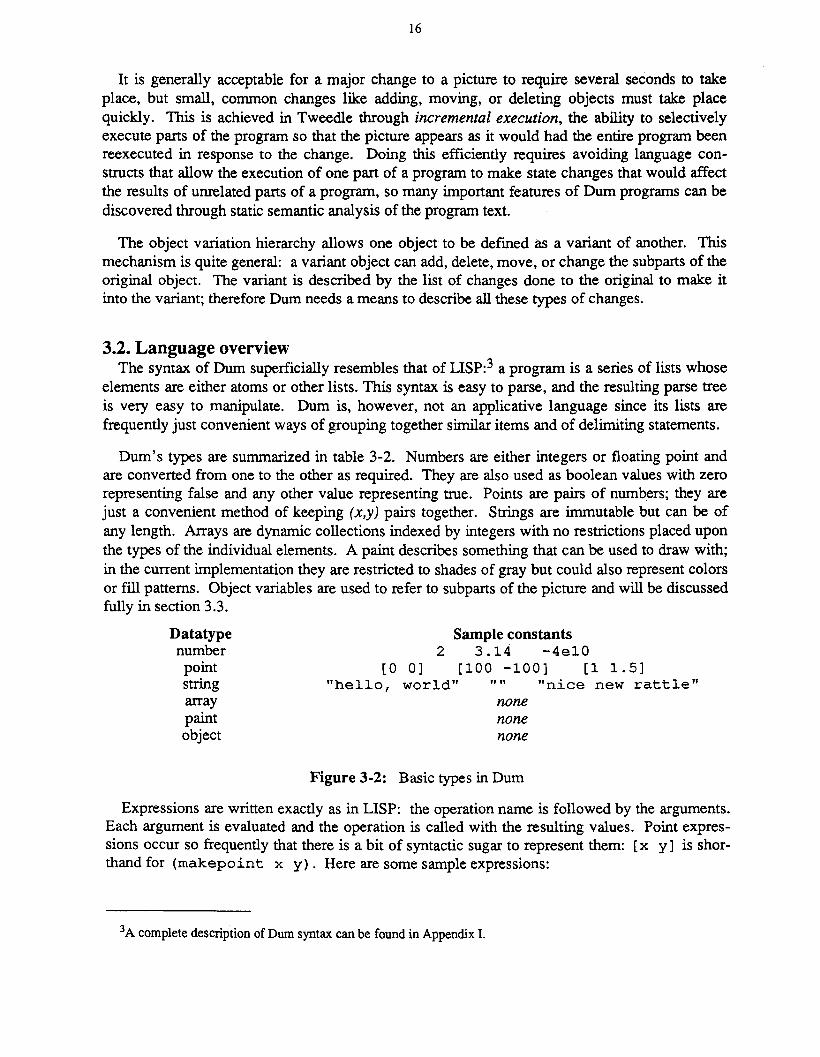
Dum's types are sununarized in table 3-2. Numbers are either integers or floating point andare converted from one to the other as required. They are also used as boolean values with zerorepresenting false and any other value representing true. Points are pairs of numbers; they arejust a convenient method of keeping (x,y) pairs together. Strings are immutable but can be ofany length. Arrays are dynamic collections indexed by integers with no restrictions placed uponthe types of the individual elements. A paint describes something that can be used to draw with;in the current implementation they are restricted to shades of gray but could also represent colorsor fill patterns. Object variables are used to refer to subparts of the picture and will be discussedfully in section 3.3.
Datatypenumberpointstringarraypaintobject
Sample constants2 3.14 -4el0
[0 0 ] [ 1 0 0 - 1 0 0 ] [11 • 5 ]"hello, world" "" "nice new rattle"
nonenonenone
Figure 3-2: Basic types in Durn
Expressions are written exactly as in LISP: the operation name is followed by the arguments.Each argument is evaluated and the operation is called with the resulting values. Point expressions occur so frequently that there is a bit of syntactic sugar to represent them: [x y] is shorthand for (makepoint x y). Here are some sample expressions:
3A completedescription of Dumsyntaxcan be foundin Appendix 1.
17
17[(* r (cos theta» (* r (sin theta»](sqrt (+ (* x x) (* y y)))(concat (translate [100 100]) (rotate 45»
Dum contains most of the features found in any ALGOL-like language; It Just uses moreparentheses to express them than usual. A program can contain if, for, while, begin, and assignment statements. Variables must be defined before they are used; however, data definition statements can be freely mixed with executable code. Since arrays can contain values of differenttypes, all type-checking in assignments and routine calls is done at runtime.
There are two types of subroutines in Dum, functions and object definitions. Object definitions can, to a first approximation, be thought of as functions that return objects. Two featuresguarantee that subroutines act as strict mathematical functions: arguments are always passed byvalue, and no non-local references are allowed. Since there are no side effects, a change in asubroutine can only affect those parts of the program that use the subroutine's value. Thislocality allows the incremental execution mechanism to bound the amount of the program thatneeds to be reexecuted in response to a change. Furthermore, the behavior of a subroutine istotally specified by its parameters, so the interpreter can call subroutines without worrying aboutthe global context.
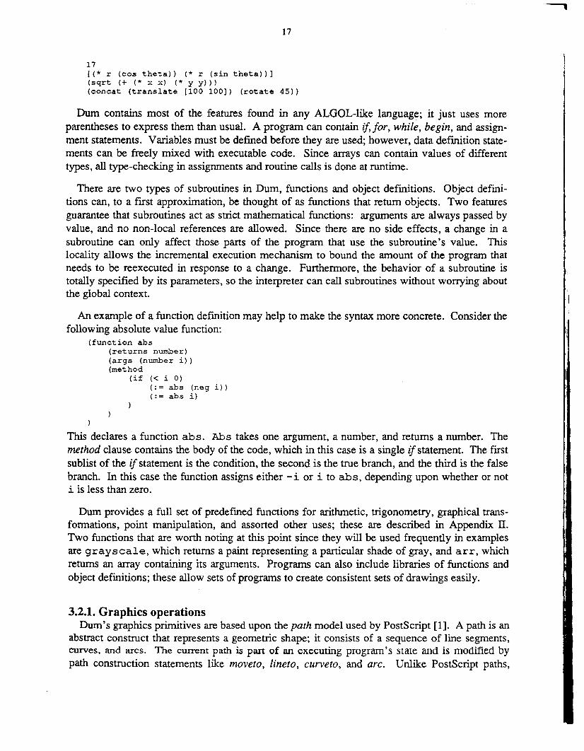
An example of a function defmition may help to make the syntax more concrete. Consider thefollowing absolute value function:
(function abs(returns number)(args (number i»(method
(if « i 0)( : = abs (neg i))(:= abs i)
)
This declares a function abs. Abs takes one argument, a number, and returns a number. Themethod clause contains the body of the code, which in this case is a single if statement. The firstsublist of the if statement is the condition, the second is the true branch, and the third is the falsebranch. In this case the function assigns either -i or i to abs, depending upon whether or noti is less than zero.
Dum provides a full set of predefmed functions for arithmetic, trigonometry, graphical transformations, point manipulation, and assorted other uses; these are described in Appendix n.Two functions that are worth noting at this point since they will be used frequently in examplesare grayscale, which returns a paint representing a particular shade of gray, and arr, whichreturns an array containing its arguments. Programs can also include libraries of functions andobject definitions; these allow sets of programs to create consistent sets of drawings easily.
3.2.1. Graphics operationsDum's graphics primitives are based upon the path model used by PostScript [1]. A path is an
abstract construct that represents a geometric shape; it consists of a sequence of line segments,curves, and arcs. The current path is part of an executing program's state and is modified bypath construction statements like moveto, lineto, curveto, and arc. Unlike PostScript paths,
18
which use Bezier cubics, Dum paths use a single point to specify curved segments and rely uponother points in the path to condition the curve. This was done primarily out of expediency: theX Window System that was used to implement Dee only supports simple splines [12].
Dum programs produce graphical output by executing drawpath and fillpatb statements.These are compound statements; within them path construction statements define the path to bedrawn or filled. Options such as the line width and the fill paint are specified as part of thestatement. If a path contains another path, the options of the subpath override those of the mainpath for the duration of the subpath and the main path's options are restored when the subpath isover. Paths can also contain objects, to be discussed fully in the next section.
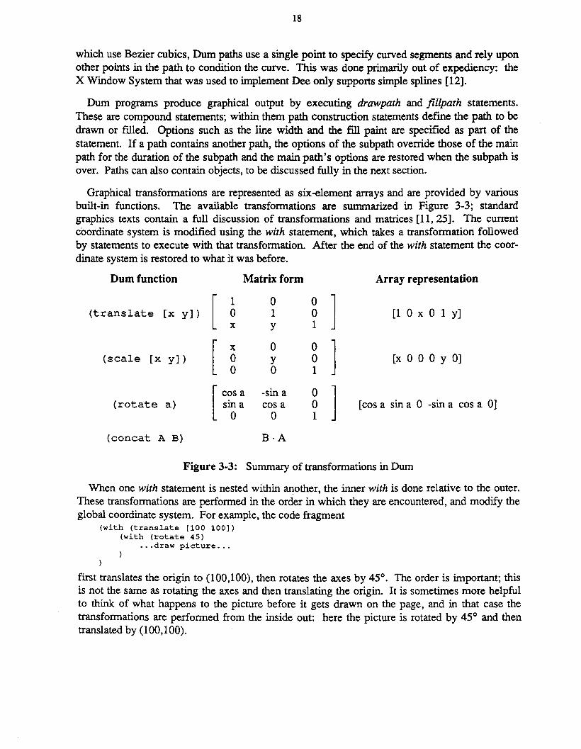
Graphical transformations are represented as six-element arrays and are provided by variousbuilt-in functions. The available transformations are summarized in Figure 3-3; standardgraphics texts contain a full discussion of transformations and matrices [11, 25]. The currentcoordinate system is modified using the with statement, which takes a transformation followedby statements to execute with that transformation, After the end of the with statement the coordinate system is restored to what it was before.
Dum function
(translate [x y)
(scale [x y)
(rotate a)
(concat A B)
Matrix form
[ 1 0 0 ]0 1 0x Y 1
[ x 0 0 ]0 y 00 0 1
[ cos a -sin a 0 ]sm a cos a 00 0 1
B·A
Array representation
[lOx 0 1 y]
[x 0 0 0 y 0]
[cos a sin a 0 -sin a cos a 0]
Figure 3-3: Summary of transformations in Dum
When one with statement is nested within another, the inner with is done relative to the outer.These transformations are performed in the order in which they are encountered, and modify theglobal coordinate system. For example, the code fragment
(with (translate [100 100])(with (rotate 45)
... draw picture ...
)
first translates the origin to (100,100), then rotates the axes by 45°. The order is important; thisis not the same as rotating the axes and then translating the origin. It is sometimes more helpfulto think of what happens to the picture before it gets drawn on the page, and in that case thetransformations are performed from the inside out: here the picture is rotated by 45° and thentranslated by (100,100).
19
The current transformation, the current path, and the current values of the path options collectively determine the graphic state of an executing program. These can only be changed by thewith, drawpath, and jillpath statements, and all revert to their previous values upon the completion of the controlling statment. Changes to the graphic state are thus statically limited byprogram constructs, so it is possible for the interpreter to save the state at the time of some subroutine execution and to restore it should the subroutine need to be reexecuted at a later time.Unrelated parts of the program cannot affect the state, so the interpreter can know that the savedstate is still correct.
The current graphic state is quite invisible to program execution since there are no functionsthat query it. This has both advantages and disadvantages. Operations that query the global stateare really just global variables in disguise; were they included, subroutines would no longer bemathematical functions. Different invocations with the same arguments might yield differentresults. On the other hand, the current system lacks adaptability. One advantage ofprocedurality is that objects can modify their appearance based upon their context, showing moreor less detail, for example, depending upon their size. This ability is lost since there is no wayfor the object to determine what the current transformation actually is.
3.3. Object semanticsThe object is the central mechanism in Dum for structuring pictures and in Dee for controlling
incremental execution. Objects represent distinct manipulable portions of the drawing, and arethus somewhat similar to segments in Core or GKS [37, 38]. More concretely, an object is abinding of a path with a transformation to place the path in the picture. If an object represents apiece of text, a character string and a font replace the path.
It is important to keep distinct several related concepts involving objects. An object definitionis a section of code that defines the appearance and behavior of an object. An object instance,also called an instantiation or simply an object, is the above mentioned path and transformationpair. The type of an object is its definition; two objects are of the same type if they are bothinstantiations of the same object definition, An object reference is a pointer to an object, and anobject variable is a variable that holds an object reference. Object references can also be storedin arrays, so anywhere an object variable is required an array element can also be used.
An object can contain other objects as parts; a component part is called a subobject and thecontaining object the parent object.
While segments in Core or GKS and objects in Dum can be manipulated in similar ways, theirdefinitions are very different. A segment has a name, and a program defines the appearance of asegment by calling subroutines that add displayable objects to the segment. Code that defines aparticular segment could be scattered throughout the program that uses it. In Dum, an objectdefinition is just a procedure that draws the object. When an object definition is called, theinterpreter creates a new object with an empty path and a copy of the current transformation.Draw, drawpath and fillpath statements inside the object do not modify the display but insteadadd their paths to the object's path. The value of a call to an object definition is a reference tothe object that was just created. The object's path is actually drawn when a reference to it isused in a draw statement.

..
20
This separation of object creation and object drawing arises because there are times when aprogram needs to defer drawing. Filled objects are opaque, and objects drawn later obscureobjects already on the display. Furthermore, certain positioning information about an object isavailable to the program whether the object has been drawn or not.
Figure 3-4: A sunburst
The center of a circle is one example of this positioning information, and it was used to createthe sunburst in Figure 3-4. This picture was made by creating an opaque circle but not drawingit, then using the center of the circle to position the outward radiating lines. The circle was thendrawn, covering the center portions of the lines.
The positioning information takes the form of control points, point values defined within anobject definition but accessible outside. The control points for a rectangle object might be thefour comers, the centers of the sides, and the center of the rectangle. The primary uses for control points are to specify points that other objects can use for aligrunent and to specify whichpoints will be gravity active in the editor. The first use is the most common and allows, forexample, arrows to point to sides of boxes, captions to center themselves, and, in the above sunburst example, the radiating lines to use the center of the circle as an endpoint. The effect ofgravity will be described in the chapter on the Dee editor.
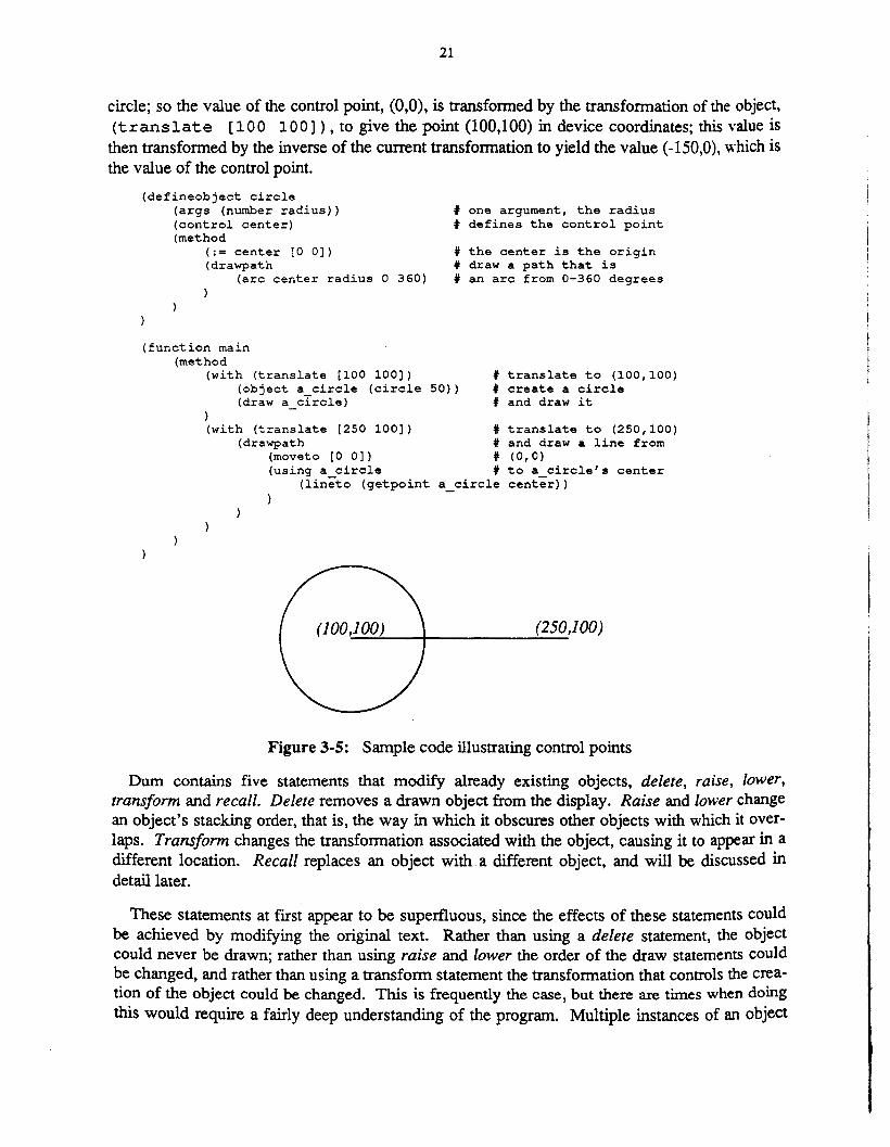
Within an object definition a control point acts just like any local point variable. Outside, theprogram obtains its value by using the getpoint operation, (getpoint <objectreference> <control point name». Getpoint is not a function since its second argument is not a normal value. The value of a getpoint operation is the value assigned to thecontrol point within the object definition, transformed by the object's transformation, and theninversely transformed by the current transformation. For example, consider the code shown inFigure 3-5. Here, the object circle has defined the control point center and assigned it thevalue [0 0] in its definition. The main program instantiates a circle with a translation of(100,100) and calls it a circle. It then changes the coordinate system to a translation of(250,100) and draws a line from (0,0) to the center of a_ circle.4 (0,0) in the new translatedcoordinate system becomes (250,100) in device coordinates. The value of the control point mustbe the value that, when transformed by the current transformation, will yield the center of the
4-rhe using statement surrounding the lineto statement will be described shortly and can be ignored for now.
21
circle; so the value of the control point, (0,0), is transformed by the transformation of the object,(translate [100 100]), to give the point (100,100) in device coordinates; this value is
then transformed by the inverse of the current transformation to yield the value (-150,0), which isthe value of the control point.
(defineobject circle(args (number radius»(control center)(method
(:= center [0 0])(drawpath
(arc center radius 0 360)
t one argument, the radiust defines the control point
t the center is the origint draw a path that ist an arc from 0-360 degrees
(function main(method
(with (translate [100 100])(object a circle (circle 50»)(draw a_circle)
t translate to (100,100)t create a circlet and draw it
)(with (translate [250 100l)
(drawpath(moveto [0 0])(using a circle
(lineto (getpoint a
tttt
circle
translate to (250,100)and draw a line from(0,0)to a circle's centercenter) )
(250,100)
Figure 3-5: Sample code illustrating control points
Dum contains five statements that modify already existing objects, delete, raise, lower,transform and recall. Delete removes a drawn object from the display. Raise and lower changean object's stacking order, that is, the way in which it obscures other objects with which it overlaps. Transform changes the transformation associated with the object, causing it to appear in adifferent location. Recall replaces an object with a different object, and will be discussed indetail later.
These statements at first appear to be superfluous, since the effects of these statements couldbe achieved by modifying the original text. Rather than using a delete statement, the objectcould never be drawn; rather than using raise and lower the order of the draw statements couldbe changed, and rather than using a transform statement the transformation that controls the creation of the object could be changed. This is frequently the case, but there are times when doingthis would require a fairly deep understanding of the program. Multiple instances of an object
22
may be created within a for or while loop, and the appropriate modification in this case is difficult to discover.P More important, these statements allow the object variation hierarchy to exist.
In the object variation hierarchy, one object is defined to be a variant of another; these objectsare called the variant and the original objects. The definition of a variant object is a list ofoperations to perform on the original in order to change it into the variant. These operations caninclude adding new subobjects, moving around existing subobjects, or even replacing these subobjects with others. When the interpreter is called upon to execute the defmition of a variantobject, it first executes the code of the original object and then, using the same values for alllocal variables, executes the code of the variant. The variant can thereby use the values of anyvariables in the original. A variant takes the same argument list as its original, followed optionally by some additional parameters.
This variation mechanism is very powerful, since it allows the variants to follow later changesmade to the original. As long as all the variables that the variant depends upon are defined thevariant will continue to make sense; if they are not, a runtime error occurs. An additional advantage of variants is that they inherit the control points of the original object. A node in a graphcould define itself as a variant circle and thereby inherit whatever control points have alreadybeen defined for circle.
Figures 3-6 and 3-7 show an example of the variation mechanism. The object defined inFigure 3-6 draws a label centered in an oval; this was used in various figures throughout thisthesis. It consists of two subobjects, a scaled circle to generate the oval and a Iabel.6 The variantobject is the same except that it shows two lines of text in the oval. The original line of text ismoved to a new position, and then the new second argument is used to generate the second lineof text. Since the two-line module is a variant object, changes to the original like alterting theline width or using a different font will automatically apply to the variant.
The transformation of an object is bound when the object is created, not when the object isdrawn. The most important reason for this is to assure that an object's control points havevalues, even though the object itself has not yet been drawn. A second reason is that somestructured types of drawings may want to pass objects to other objects and have them drawnthere. This is best illustrated by an example.
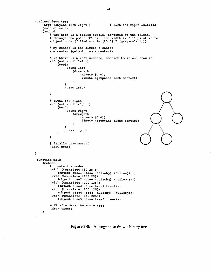
Figure 3-8 show a program to draw a binary tree. The main program creates all the nodes,placing them as it wishes. The structure of the tree is built by passing to each tree the two trees itshould use as its left and right subtrees. The code that defines the tree creates a node for itself,draws connecting lines to the subtrees, draws the subtrees.f and finally draws its own node. Themain program has only to draw the final tree and the entire structure appears. Since the transformations are bound at creation time, the code for the tree need not worry about positioning thetwo subtrees.
SPar causes fewer problems since the index variable can be tested; while loops are virtually impossible.
&rhe exact arguments to the circle object are irrelevant here.
7Once again, ignore the using statement for now.

23
(defineobject module (args (string legend»(control left right top bottom ne nw se sw center)(method
(with (scale [1.5 1])(object oval (circle [1 25] 2»(draw oval)
)(number f (getfont "times" 14»(number w (strwidth legend f»
(with (translate [(* -0.5 w) -5])(object the label (text legend f»(draw the_label)
# code omitted that assigns the control points
Figure 3-6: A labelled oval(defineobject 2 line module (variant module)
(args (string-line2»(method
(transform the label (translate [(* -0.5 w) 2]»(:= w (strwidth line2 fl)(with (translate [(* -0.5 w) -13])
(object 2nd label (text line2 f»(draw 2nd_label)
Figure 3-7: A variant with two lines of text
The editor can change an object's transformation either by changing the transformation in effect at the object's creation or by adding a transform statement to the end of the program.Whichever method is used, the editor then has the job of making sure the picture looks as if theobject had always been in its new location. Simply moving the object is not enough; since thecalculation of a control point's value includes its object's transformation, the values of theobject's control points change. If the picture is to remain consistent, all parts of the programwhose results depend upon the values of these control points must be reexecuted.
In order to do this the interpreter creates for each object a list of code segments whose resultsdepend upon the object's control point values. Each of these segments needs to be complete;that is, any part of the program not in the list of segments must execute in the same way nomatter what the values of the control points may be. In many cases the segments are both obvious and quite self-contained. Most getpoint operations occur in path construction statementsor as arguments to other objects, and in both of these cases the interpreter has no difficulty indetermining how much code needs reexecution: in the first case it is the path construction statement, in the second, the object invocation. Neither reexecution can cause distant sections ofcode to become incorrect, although if an object gets reinvoked the values of its control points canin tum change, causing ripples of reexecution to spread throughout the program. The true difficulty occurs when the value of a control point affects later execution. A program can test acontrol point in an if statement, for example, or assign its value to a point variable and use thevariable later in the program. In these cases a changed control point can cause later execution tochange in arbitrary and unpredictable ways. While these uses of control points are rare, they are
24
(defineobject tree(args (object left right» t left and right subtrees(control center)(method
t the node is a filled circle, centered at the origin,t through the point [25 0], line width 2, fill paint white(object node (filled_circle [25 0] 2 (grayscale 1»)
t my center is the circle's center(:= center (getpoint node center»
t if there is a left subtree, connect to it and draw it(if (not (null left»
(begin(using left
(drawpath(moveto [0 0])(lineto (getpoint left center»
)(draw left)
t ditto for right(if (not (null right»
(begin(using right
(drawpath(moveto [0 0])(lineto (getpoint right center»
)(draw right)
t finally draw myself(draw node)
(function main(method
t create the nodes(with (translate [50 25])
(object treel (tree (nullobj) (nullobj»»(with (translate [150 25])
(object tree2 (tree (nullobj) (nullobj»»(with (translate [100 125])
(object tree3 (tree treel tree2»)(with (translate [200 125])
(object tree4 (tree (nullobj) (nullobj»»(with (translate [150 225])
(object tree5 (tree tree3 tree4»)
t finally draw the whole tree(draw tree5)
Figure 3..8: A program to draw a binary tree
25
useful; for example, a program might want to test an object's position, and, depending whetherthe object is above or below a particular point, draw an arrow to the bottom or the top of theobject.
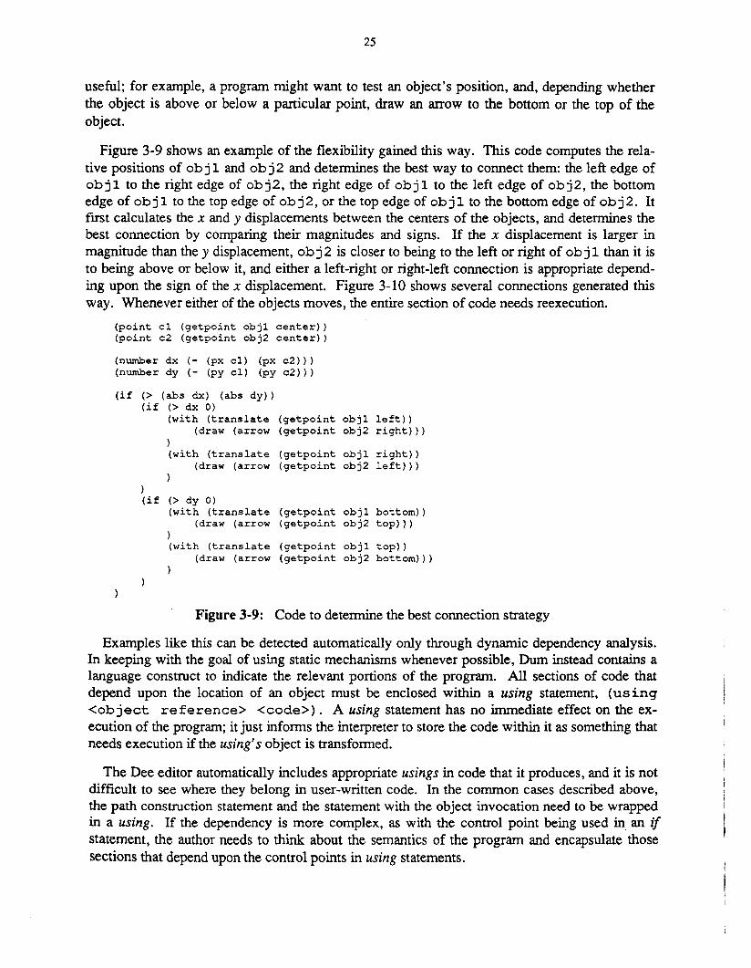
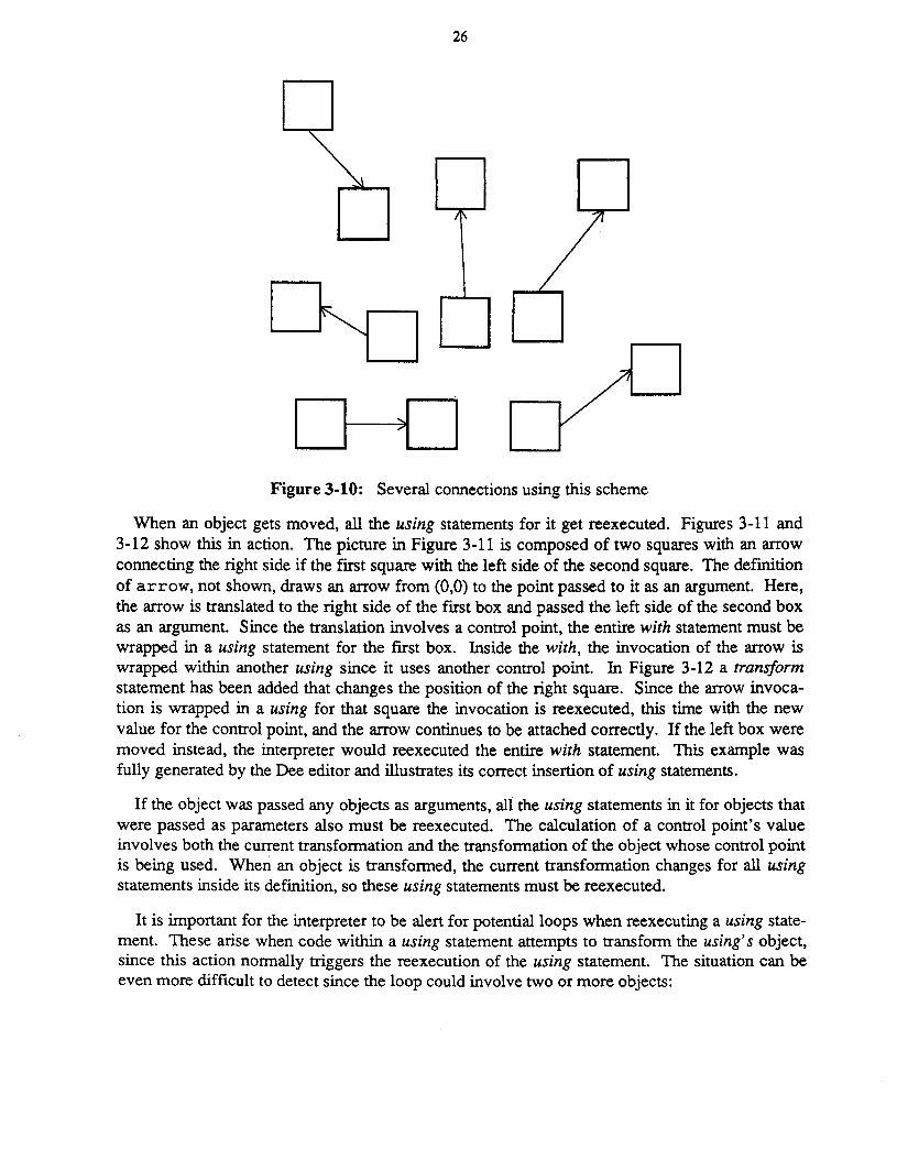
Figure 3-9 shows an example of the flexibility gained this way. This code computes the relative positions of ob j 1 and ob j 2 and determines the best way to connect them: the left edge ofob j 1 to the right edge of ob j 2, the right edge of ob j 1 to the left edge of ob j 2, the bottomedge of ob j 1 to the top edge of ob j 2, or the top edge of ob j 1 to the bottom edge of ob j 2. Itfirst calculates the x and y displacements between the centers of the objects, and determines thebest connection by comparing their magnitudes and signs. If the x displacement is larger inmagnitude than the y displacement, ob j 2 is closer to being to the left or right of ob j 1 than it isto being above or below it, and either a left-right or right-left connection is appropriate depending upon the sign of the x displacement. Figure 3-10 shows several connections generated thisway. Whenever either of the objects moves, the entire section of code needs reexecution.
(point c1 (getpoint obj1 center»(point c2 (getpoint obj2 center»
(number dx (- (px c1) (px c2»)(number dy (- (py c1) (py c2»)
(if (> (abs dx) (abs dy)(if (> dx 0)
(with (translate (getpoint obj1 left) )(draw (arrow (getpoint obj2 right» )
)(with (translate (getpoint obj1 right) )
(draw (arrow (getpoint obj2 left) ) )
)(if (> dy 0)
(with (translate (getpoint objl bottom»(draw (arrow (getpoint obj2 top»)
)(with (translate (getpoint objl top»
(draw (arrow (getpoint obj2 bottom»)
Figure 3-9: Code to determine the best connection strategy
Examples like this can be detected automatically only through dynamic dependency analysis.In keeping with the goal of using static mechanisms whenever possible, Dum instead contains alanguage construct to indicate the relevant portions of the program. All sections of code thatdepend upon the location of an object must be enclosed within a using statement, (using<object reference> <code». A using statement has no immediate effect on the execution of the program; it just informs the interpreter to store the code within it as something thatneeds execution if the using's object is transformed.
The Dee editor automatically includes appropriate usings in code that it produces, and it is notdifficult to see where they belong in user-written code. In the common cases described above,the path construction statement and the statement with the object invocation need to be wrappedin a using. If the dependency is more complex, as with the control point being used in an ifstatement, the author needs to think about the semantics of the program and encapsulate thosesections that depend upon the control points in using statements.
26
I 1r---1 I
1'\
Figure 3-10: Several connections using this scheme
When an object gets moved, all the using statements for it get reexecuted. Figures 3-11 and3-12 show this in action. The picture in Figure 3-11 is composed of two squares with an arrowconnecting the right side if the first square with the left side of the second square. The defmitionof arrow, not shown, draws an arrow from (0,0) to the point passed to it as an argument. Here,the arrow is translated to the right side of the first box and passed the left side of the second boxas an argument. Since the translation involves a control point, the entire with statement must bewrapped in a using statement for the first box. Inside the with, the invocation of the arrow iswrapped within another using since it uses another control point. In Figure 3-12 a transformstatement has been added that changes the position of the right square. Since the arrow invocation is wrapped in a using for that square the invocation is reexecuted, this time with the newvalue for the control point, and the arrow continues to be attached correctly. If the left box weremoved instead, the interpreter would reexecuted the entire with statement. This example wasfully generated by the Dee editor and illustrates its correct insertion of using statements.
If the object was passed any objects as arguments, all the using statements in it for objects thatwere passed as parameters also must be reexecuted. The calculation of a control point's valueinvolves both the current transformation and the transformation of the object whose control pointis being used. When an object is transformed, the current transformation changes for all usingstatements inside its definition, so these using statements must be reexecuted.
It is important for the interpreter to be alert for potential loops when reexecuting a using statement. These arise when code within a using statement attempts to transform the using's object,since this action normally triggers the reexecution of the using statement. The situation can beeven more difficult to detect since the loop could involve two or more objects:
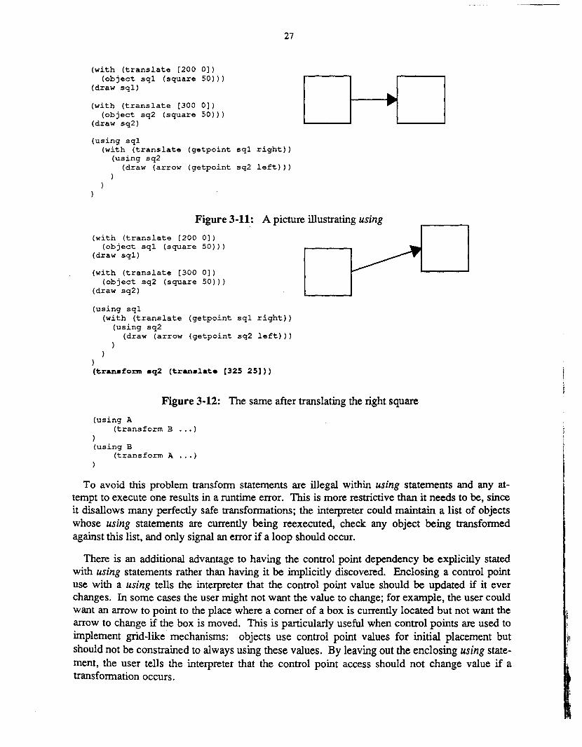
27
(with (translate [200 0])(object sql (square 50»)
(draw sql)
(with (translate [300 0])(object sq2 (square 50»)
(draw sq2)
(using sql(with (translate (getpoint sql right»
(using sq2(draw (arrow (getpoint sq2 left»)
I I , I
Figure 3-11: A picture illustrating using
(with (translate [200 0])(object sql (square 50»)
(draw sql)
{with (translate [300 0])(object sq2 (square 50»)
(draw sq2)
(using sql(with (translate (getpoint sql right»
(using sq2(draw (arrow (getpoint sq2 left»)
)(tranaform aq2 (tranalate [325 25]»
Figure 3-12: The same after translating the right square
(using A(transform B ... )
)(using B
(transform A ... )
To avoid this problem transform statements are illegal within using statements and any attempt to execute one results in a runtime error. This is more restrictive than it needs to be, sinceit disallows many perfectly safe transformations; the interpreter could maintain a list of objectswhose using statements are currently being reexecuted, check any object being transformedagainst this list, and only signal an error if a loop should occur.
There is an additional advantage to having the control point dependency be explicitly statedwith using statements rather than having it be implicitly discovered. Enclosing a control pointuse with a using tells the interpreter that the control point value should be updated if it everchanges. In some cases the user might not want the value to change; for example, the user couldwant an arrow to point to the place where a comer of a box is currently located but not want thearrow to change if the box is moved. This is particularly useful when control points are used toimplement grid-like mechanisms: objects use control point values for initial placement butshould not be constrained to always using these values. By leaving out the enclosing using statement, the user tells the interpreter that the control point access should not change value if atransformation occurs.
28
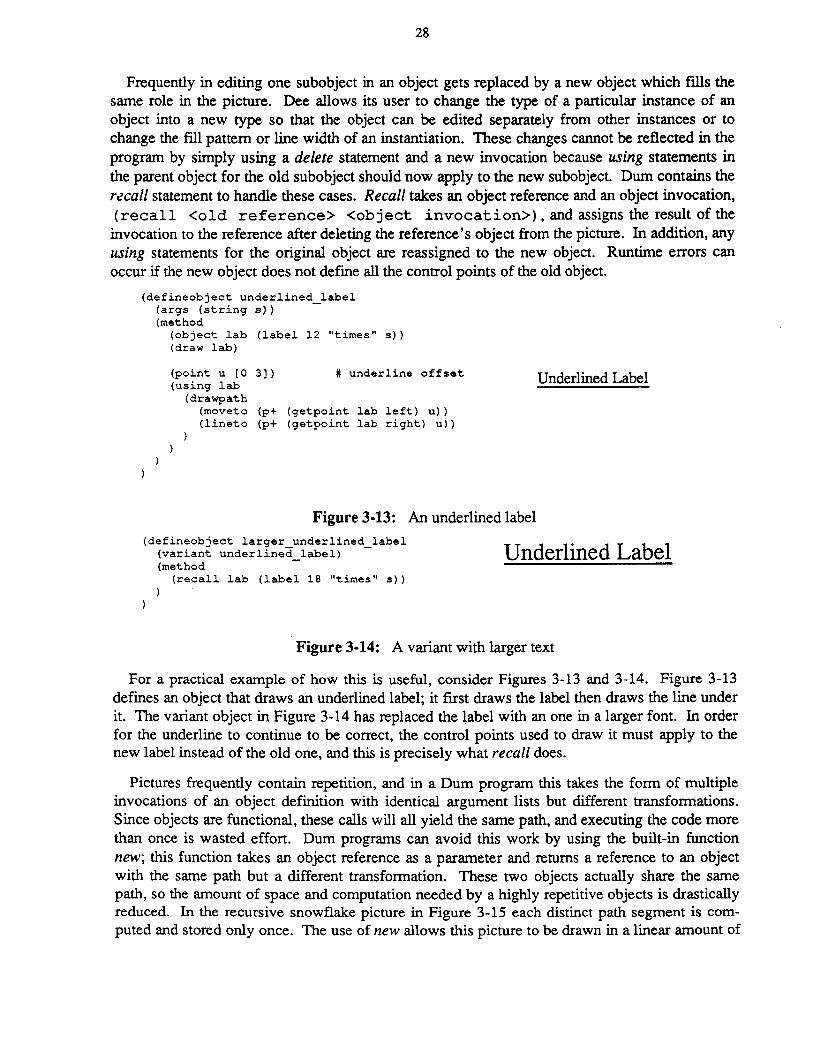
Frequently in editing one subobject in an object gets replaced by a new object which fills thesame role in the picture. Dee allows its user to change the type of a particular instance of anobject into a new type so that the object can be edited separately from other instances or tochange the fill pattern or line width of an instantiation. These changes cannot be reflected in theprogram by simply using a delete statement and a new invocation because using statements inthe parent object for the old subobject should now apply to the new subobject. Dum contains therecall statement to handle these cases. Recall takes an object reference and an object invocation,(recall <old reference> <object invocation», and assigns the result of the
invocation to the reference after deleting the reference's object from the picture. In addition, anyusing statements for the original object are reassigned to the new object. Runtime errors canoccur if the new object does not define all the control points of the old object.
(defineobject underlined label(args . (string s ) -(method
(object lab (label 12 "times" s»(draw lab)
(point u [0(using lab
(drawpath(moveto(lineto
3]) t underline offset
(p+ (getpoint lab left) u»{p+ (getpoint lab right) u»
Figure 3-13: An underlined label
Underlined Label
(defineobject larger underlined label(variant underlined label) -(method -
(recall lab (label 18 "times" s»
Underlined Label
Figure 3-14: A variant with larger text
For a practical example of how this is useful, consider Figures 3-13 and 3-14. Figure 3-13defines an object that draws an underlined label; it first draws the label then draws the line underit. The variant object in Figure 3-14 has replaced the label with an one in a larger font. In orderfor the underline to continue to be correct, the control points used to draw it must apply to thenew label instead of the old one, and this is precisely what recall does.
Pictures frequently contain repetition, and in a Dum program this takes the form of multipleinvocations of an object definition with identical argument lists but different transformations.Since objects are functional, these calls will all yield the same path, and executing the code morethan once is wasted effort. Dum programs can avoid this work by using the built-in functionnew; this function takes an object reference as a parameter and returns a reference to an objectwith the same path but a different transformation. These two objects actually share the samepath, so the amount of space and computation needed by a highly repetitive objects is drasticallyreduced. In the recursive snowflake picture in Figure 3-15 each distinct path segment is computed and stored only once. The use of new allows this picture to be drawn in a linear amount of

29
time and space as a function of the maximum recursion depth; without new it would requireexponential time and space.
Figure 3-15: A picture with a high degree of repetition
Using new is completely transparent; the new object appears and behaves exactly as it wouldhave had it resulted from a call to the appropriate object definition. If the arguments to theobject being new'ed contain any object references, the new function actually does call the appropriate definition. This is because the object being called presumably uses some of the controlpoints of the passed object, and the relation between the called object and the passed object willbe different in the two cases. This is also completely transparent; the program can always callnew with impugnity.
This path sharing among different instances of an object places some restrictions upon the waytransformations are stored in an object. In particular, the transformations of subobjects must bestored relative to the transformation of their parent object. Using relative transformations has theadditional benefit that when objects are moved, the editor need not update the transformations ofsubobjects. When drawing, a transformation stack is maintained so that local coordinates Can bemapped into global coordinates.
One unfortunate side effect of using relative transformations arises when an object is drawn byan object other than the one that created it; this occurs in the binary tree example on page 24.This is a manifestation of the classic funarg problem that arises in programming languages whenfunctions that have been passed to other functions attempt to do non-local references. To resolvethis problem, an object must maintain enough information to enable the drawing routines to findits creator.
30
3.4. Why a new language?One question not yet addressed is whether or not a new language is actually necessary. Would
another language serve equally well? One likely candidate is PostScript [1], a language, likeDurn, explicitly designed to represent images. PostScript is especially attractive since manyprograms produce it as output, and being able to interactively edit these files would be a valuabletool. Although Dum and PostScript share some parts of their imaging models, there are somefundamental differences that make PostScript unsuitable as an interactive representation. Areview of Dum's language design goals will show how Dum satisfies these goals and why otherlanguages, particularly PostScript, do not.
The first goal is conventionality. Dum contains all the features commonly found in standardimperative programming languages: variables, arrays, functions, assignments, for and whileloops, and if statements. PostScript also has these features; their syntax and underlying semantics may be unusual but the features themselves are not.
Another goal is simplicity, and both Dum and PostScript succeed here. A Dum program is asequence of lists containing other lists and atoms, while a PostScript program is just a sequenceof stack-based operations and their operands. The need for simplicity is the primary thing thatkeeps other languages from being appropriate.
The biggest difference between Dum and PostScript is Dum's use of static structure tofacilitate incremental execution. Many program properties that would require simulated execution to discover in PostScript can be found in Dum programs through static semantic analysis ofthe source text. All changes to the graphics state of a Dum program are statically bounded bydrawpath, jillpath, and with statements, so the interpreter can determine the graphics state at anypoint by inspecting the program. If the program is changed to modify the graphics state theinterpreter can tell just what part of the program is affected by the change. This is very differentfrom the way PostScript handles state changes since PostScript programs change the graphicstate by executing operators that can be anywhere. For example, the PostScript code
i 0 eq % test if i '" 0
45 rotate % and rotate axes by 45 degrees
100 100 translate % or translate origin to (100,100)ifelse % depending upon the value
% what is the current transformation now?
leaves the current transformation rotated by 45° if the value of i is 0 and translated to (100,100)if it isn't. These state changes may even be tucked away inside drawing functions:
Ibox { % start definition of box% do some drawing operations
10 10 translate % translate the origin) def % and finish the definition
100 100 translatebox
% translate origin to (100,100)% draw a box
% origin is now translated to (110, 110)
Another way Dum uses static structure is to have all subroutines act as mathematical functions. The nesting structure of graphics state changes already guarantees that subroutine callscannot change the graphical state, and disallowing non-local references guarantees that they can-
31
not change the program state. Since subroutines cannot have side effects, the interpreter can callthem freely without causing incompatible changes to the program state, and since they cannotuse non-local variables, the amount of context associated with a call is limited to the values ofthe subroutine's parameters and local variables.
The fmal application of static structure is the using statement. Using allows the interpreter todetermine all parts of a program that rely upon the position of an object so that it can reexecutethem if that position changes. As will be seen in the next chapter, using also enables the incremental execution mechanism to find what parts of a program require reexecution if the definition of an object changes. PostScript has no formal notion of graphical objects, so it has noconstruct analogous to using.
The last goal is having an object variation hierarchy. Dum allows an object's subobjects to bemanipulated with statements like transform, recall, and raise; these permit the program tochange the graphical output of an object interactively. The idea of having subparts of the picturechange after they have been drawn is dramatically different from PostScript's graphics model.PostScript uses a simulated paint model for graphics: the picture is created by placing areas ofopaque ink upon the current page, and once the ink is on the page it cannot be erased or moved.There are no commands in PostScript to manipulate a picture once it has been produced.
Although Dum and PostScript differ greatly semantically, they share many statements andfunctions. This enables anyone familiar with PostScript to understand and write Dum code withfew difficulties. Further, many programs that generate PostScript for hard copy could easily bechanged to generate Dum instead and thereby produce pictures that can be edited with Dee.
32
4. The Graphics EditorFigures 4-1 and 4-2 illustrate the basic difference between the structure of conventional
graphics editors and the structure of the Dee editor. The Dum language interpreter forms theheart of the Dee editor; whenever the user changes the picture the editor generates new code andpasses it to the interpreter for execution. The execution of this code in tum generates changes tothe displayed picture. This chapter will describe the editor, concentrating on how the interpreterincrementally executes program changes to keep the picture consistent.
Updates
Picture
Figure 4-1: The flow of information in a conventional editor
Updates
Picture
Code
Commands
Figure 4-2: The flow of information in the Dee editor
4.1. Incremental executionThe execution of any program in any language can be thought of on two levels. It is first a
series of transformations upon some set of objects that collectively comprise the internal state ofthe system. But it is also a series of side effects like printing values or drawing on a screen, andit is the production of these side effects that is often the real goal of running the program. Theline between these effects is sometimes a little fuzzy; updating a file can be thought of as changing the state if the file is considered as part of the state or as a side effect if it is not. In Dumprograms the division is quite clear: a program modifies its variables and it produces a picture asa side effect.

33
When a program changes, it needs to be rerun so that the resulting picture will reflect thechanges to the program. Since every editing operation in Dee corresponds to some change to theunderlying Dum program, these changes occur very frequently and good interactive responserequires that the resulting reexecution be done quickly. Any individual change can have twokinds of effects: it can change the way the program transforms the internal state, and it canchange the side effects that the program generates. Having the interpreter produce the correctside effect changes is a fairly straightforward exercise in manipulating data structures; the nextchapter will discuss how it does this. Handling internal state changes is a much more interestingproblem.
initialcode
Figure 4-3: How changing code affects the program state
It is useful at this point to distinguish between two types of program changes: structuralchanges and content changes. Structural changes affect the way various program components fittogether. These can include deleting subroutines, changing objects definitions into functions orvice versa, changing the return types of functions, and changing the number or types of subroutine arguments. Content changes, on the other hand, change the internal code of subroutinesor add new subroutines but do not change how the subroutines interconnect. When a structuralchange occurs the editor reexecutes the program in its entirety; however, with content changes itcan often get by by executing only a subset of the program. Structural changes are quite rare, sothe extra time needed to respond to them is not a problem.
Figure 4-3 shows how the interpreter can avoid executing the entire program in response to acontent change. Initially the program contains a block of code that transforms state 1 into state2, and this is followed by some additional code that transforms state 2 into state 3. If the firstblock is changed, state 1 gets transformed into a new state, state 2' , which may be different fromthe original state 2. After execution of the following code, however, the state may once again bethe same as it was in the original execution. Any side effects produced before the programentered state 1 will be the same as before because the changed code has not yet been encountered, and any side effects produced after state 3 will be the same as before because the programis proceeding from the same state.
The challenge here is identifying the second block of code, that is, to identify how much of theprogram after the change needs to execute in order to return the state to what it was in theoriginal execution. In some cases, no amount of extra code will satisfy the requirement; the stateremains different even after executing the rest of the program. Dum, however, was designed so
34
that common editing operations change the state only in carefully controlled ways so the interpreter needs to execute very little extra code to restore its state. Frequently state 2' is the sameas state 2, and in these cases no extra code needs execution.
As discussed in the previous chapter, Dum's static structure bounds changes to the graphicsstate and forces subroutines to have no side effects. The first feature mostly comes into play indetermining the extent of the effects when the user modifies the text of the program. If graphicsstate changes were unbounded, the user could change the code segment
(object a_shape (triangle))
into# this is not legal Dum code(translate [20 20])(object a_shape (triangle))
# translate origin by (20,20)
and thereby change the position of not' only the object a shape but also the position of everyobject that was created later in the program. The problem here is that the affected part of theexecution is not bound by the change to the text. In Dum, however, the user would change thecode either into
(with (translate [20 20])(object a_shape (triangle))
to translate just the triangle, or into(with (translate [20 20])
(object a_shape (triangle))
)
to translate the triangle and everything following. In either case, the change embraces all thecode affected by the change; there are no lingering after effects.
This is less important when the editor changes the code since it could limit itself to changesthat have no long term effects. In the above example using nonexistent state changing statements, the editor could change to code into something like
# this is not legal Dum code either(gsave) # save the graphics state(translate [20 20]) # translate origin by (20,20)(object a shape (triangle))(grestore) # put it back
The functional nature of object definitions is much more important. Since an object defmitioncannot modify nonlocal variables, the editor can insert an object invocation anywhere in theprogram without worrying what effects it will have on the code that follows: it will have noeffects whatever. It can also change the code within an object definition as much as it wishes,knowing that these changes cannot affect anything besides the actual invocations of that definition. Finally, since the definition carmot look at nonlocal variables Of. at the graphics state,changes to an object definition cannot affect the subobjects as long as their argument lists areunchanged.
A primary issue in incremental execution is establishing the appropriate granularity. When apiece of code changes, the interpreter must reestablish the program state somewhere before thecode and execute until it can be sure that the program state is consistent with what it was before.
-
j)
The interpreter must therefore save the program state at appropriate intervals during the initialexecution and use these saved states in incremental execution. The question is how frequentlythese states should get saved. Saving them too infrequently leads to extra code being executedboth before and after the change; saving them too frequently slows down execution too muchand uses a lot of storage.
The storage problem can be partially alleviated by using data compaction. Each individualsection of code is likely to change only a small part of the state, so the interpreter could save theentire state in some places and save only the changed parts in between. The problem with thisapproach is that reestablishing the state now requires reconstructing it from multiple sources;doing this is likely to be nearly as slow as executing extra code.
Dee's solution is to save the state at the beginning and the end of each execution of an objectdefinition. Saving at the beginning is easy; it only requires saving the values of the arguments.Saving at the end is done by maintaining the program execution stack as a linked list of stackframes; when an object invocation exits its stack frame is removed from the stack and saved inthe object. This allows the final variable values to be saved without doing any copying. Theinitial saved state allows the interpreter to reexecute each invocation of a changed object in isolation from the rest of the program; the final state allows it to avoid completely reexecuting thedefinition when the only change has been to add code to the end.
As discussed in the previous chapter, there are only a few ways a Dum program can use objectreferences: it can draw them, delete them, raise them, lower them, transform them, and recallthem. In particular, the only way a program can use their values to affect the flow of furtherexecution is through their control points; these can be used like any other point value. But theinterpreter knows what parts of the program depend upon the control points; these are just theparts of the program delimited by using statements for the changed object.
Thus, when an object definition changes, it suffices to reexecute each invocation of the object.The original values of the control points for each invocation are compared to the new values,and, if they vary, the using statements associated with these invocations each get reexecuted.fSince the interpreter also maintains the final state of each invocation to an object, it can extendthe executions of the objects rather than completely reexecuting them when additional code getsadded to the end of a definition. Further, when an object that has variants is changed or extended, the interpreter must also reexecute invocations of the variant objects.
There are three other kinds of content changes possible to a program: the definitions of functions can change, the main program can be extended, and the main program can change internally. The second of these cases is easily handled by saving the final state of the main programand restoring it before executing the added code. The other two situations cause more difficulties, and, should they occur, the interpreter abandons incremental execution and justreexecutes the entire program.
8No comparison is done in the current implementation; it just assumes that the control point values alwayschange.
36
The problem with function definitions is that changing a definition is likely to change itsvalue, and changing its value can affect the later execution of the program in unpredictable ways.Since most of the code in Dum programs is dedicated to producing a picture, functions are usedprimarily as support operations peripheral to the main thread of execution. This means that, inpractice, function definitions change much less frequently than object definitions, so the extraoverhead incurred when functions change is not a problem. In particular, the editor neverchanges functions; the only time they change is when the user changes them explicitly throughthe text editor. Call graph analysis could eliminate some of these full executions by reexecutingonly objects that actually use the changed function, but this was not done in the current implementation.
The problem is more severe with the main program since it changes more frequently. Manyfull executions could be avoided by saving additional state checkpoints between some of thestatements in the main program, especially towards the end where changes occur most frequently. About half of the main program changes are to the statements just added to the programby the most recent editor operation, so saving even one checkpoint would eliminate many fullexecutions. The current implementation, however, does not do this.
4.2. User interfaceFigure 4-4 shows a snapshot of the screen as it appears during an editing session with Dee.
On the left is a window containing the text of the current program, and below it are buttons forcommands that operate upon the picture as a whole. On the right is a window with the pictureand buttons for graphics editor operations. At the bottom a dialog window provides an area forDee to display messages and for the user to enter responses.
A text editor runs in the left window to allow the user to modify the program text. The currentimplementation uses a version of Emacs [13] with some customized functions to streamline editing, but Dee does not rely upon any particular features of Emacs so other editors would serveequally welL The buttons below provide the standard editing functions Read, Reread, Save,Save as, and Quit. There are also several functions unique to Dee: Do Changes, which tells theinterpreter to use incremental execution to execute the changes made manually to the text, andRecompile, which tells the interpret to fully reexecute the program. Recompile is actually superfluous since Do Changes will always discover when full reexecution is necessary; however, it issometimes useful for debugging purposes to force reexecution even when no changes have occurred. Other operations are Redraw, to refresh the screen, Generate, to generate a PostScriptfile for hard copy, and Abort, to stop the execution of a running Dum program.
The user begins a session by using the Read function to read in some saved Dum program. Anempty drawing can be obtained by reading a nonexisting file; in this case Dee initializes thedrawing with an empty main program. The interpreter executes the program, and the resultingpicture appears in the window on the right. The user is then free to manipulate the picture eitherby using the graphics editor or by editing the source.
The graphics editor uses the familiar select-then-operate mechanism: a subset of the objects inthe picture comprise the selection and the various operations act upon all selected objects. Theuser modifies the selection by pointing at objects and clicking a mouse button; depending uponwhich button is pushed the pointed-to object becomes the selection, is added to the selection, or
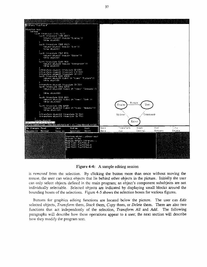
37
Add
/commandS, .'I,~
"".Update,",_,",
Figure 4-4: A sample editing session
is removed from the selection. By clicking the button more than once without moving themouse, the user can select objects that lie behind other objects in the picture. Initially the usercan only select objects defined in the main program; an object's component subobjects are notindividually selectable. Selected objects are indicated by displaying small blocks around thebounding boxes of the selections. Figure 4-5 shows the selection boxes for various figures.
Buttons for graphics editing functions are located below the picture. The user can Editselected objects, Transform them, Stack them, Copy them, or Delete them. There are also twofunctions that act independently of the selection, Transform All and Add. The followingparagraphs will describe how these operations appear to a user; the next section will describehow they modify the program text.
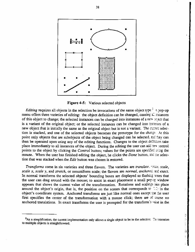
38
• • •l==:tr~'1g =
I::--:-=--
.I. .1.
1-=-1
Figure 4-5: Various selected objects
Editing requires all objects in the selection be invocations of the same object type." .!:. ?Op-upmenu offers three varieties of editing: the object defmition can be changed, causing L zstancesof this object to change; the selected instances can be changed into instances of a nev :r.:ect thatis a variant of the original object; or the selected instances can be changed into ~::::=:ces of anew object that is initially the same as the original object but is not a variant. The ~-~.: selection is stacked, and one of the selected objects becomes the prototype for the chr~ At thispoint only objects that are subobjects of the object being changed can be selected. n: ~.ey canthen be operated upon using any of the editing functions. Changes to the object de~on takeplace immediately to all instances of the object. During the editing the user can ad':~ controlpoints to the object by clicking the Control button; values for the points are specife; :s:"""1g themouse. When the user has fmished editing the object, he clicks the Done button, ::::C :-.e selection that was stacked when the Edit button was chosen is restored.
Transforms come in six varieties and three flavors. The varieties are translate. rxi:e, scale,scale x, scale y, and stretch, or nonuniform scale; the flavors are normal, anchorei. ir"-C exact.In normal transforms the selected objects' bounding boxes are displayed as flasnc; :r.xes thatthe user can drag around with the mouse; to assist in exact placement a small 1X':-~ .indowappears that shows the current value of the transformation. Rotations and scalings ::ice placearound the object's origin, that is, the position on the screen that corresponds to -: .:; in theobject's coordinate system. Anchored transforms are just like normal ones excep: :::z~ userfirst specifies the center of the transformation with a mouse click; there are 0: :"u.-rse noanchored translations. In exact transforms the user is prompted for the transform's i1£ue in the
9As a simplification, the current implementation only allows a single object to be in the selection -:-2 extensionto multiple objects is straightforward. I
iIII,
39
dialog window; the mouse is not used at all. The various types of transforms are selectedthrough a three layer pop-up menu.
Stack allows the selected objects to be either raised or lowered with respect to objects theyoverlap. If more than one object is selected the stacking is done in the order in which the objectswere selected; this is only relevant when the selected objects overlap each other.
Copy duplicates each of the selected objects. As in transforms, the selected objects' boundingboxes are dragged with the mouse.
Delete deletes each of the selected objects from the picture.
Transform All transforms every subobject in the object being edited by the same amount, or, ifthe main program is being edited, every object in the picture. It is different from the other operations in two ways: first, it ignores the current selection, and, second, it also operates upon thepaths in the current object. All the varieties and flavors of regular transforms are also availablethrough Transform All. This function is most useful for transforming the entire picture.
Add presents the user with a multiple level pop-up menu of objects that can be added. Onepane contains all objects defmed in the current program as well as the special entry new, andadditional panes contain all items defmed in libraries included in the program. Several librariesare always included by default; these provide rectangles, curves, labels, arrows, and other common objects. Dee first requests the origin for the object to be added and then requests values foreach of its parameters; a parameter name protocol specifies how Dee obtains these parametervalues. Certain parameters are provided automatically by Dee depending upon the currentvalues set by the user: these are number parameters named %linewidth and %fontsize,paint parameters named %fillpaint, and string parameters named %font. Point valuedparameters are input with the mouse, and if an array parameter is named %pointarray, Deewill fill the array with a sequence of such points. Objects parameters are picked as in the selection mechanism, and string and number parameters are requested in the dialog window.
Any time Dee requests a point, the user can chose either exact positions on the screen ornearby control points by using different mouse buttons. Control points are thus gravity active;mechanisms like grid points can be provided by including objects in the picture that produce nographical output but define control points for other objects to use.
4.2.1. Bounding boxesDee highlights selected objects by putting small squares on the screen at the comers and edges
of their bounding boxes, and gives feedback for interactive transformations by dragging bounding boxes with the mouse. Because of the semantics of objects, these bounding boxes behave inwhat may be a somewhat unexpected manner.
The bounding box of an object is defmed to be the smallest rectangle containing the objectwith sides parallel to the axes of the object's parent. If the object's parent has been rotated orscaled, however, the bounding box on the screen may not have edges parallel to the edges of thewindow and may sometimes not even be a rectangle.

40
For example, consider Figure 4-6. This shows the picture produced by invoking this objectdefinition:
(defineobject boxes(method
(with (translate [50 25])(object rectl (rectangle [75 30] 2»)
(draw rectl)
(with (concat (translate [175 25]) (rotate 30»(object rect2 (new rectl»)
(draw rect2)
(with (concat (translate [300 25]) (scale [1.5 .75]) (rotate 30»)(object rect3 (new rectl»)
(draw rect3)
~-~-jII IIl__~__~
~~. . .~:~
Figure 4-6: Bounding boxes of three objects
Figure 4-7: The same, in a rotated coordinate system
Figure 4-8: The same, in a skewed coordinate system
The three rectangles have been invoked with different transformations: the first was justtranslated, the second rotated then translated, and the third rotated, scaled, and then translated.In all three cases Dee correctly calculates the bounding box of the rectangle. If the boxesobject is rotated in the picture, the result is as in Figure 4-7. The bounding boxes are now rotatedso that their edges remain parallel to the axes of the rotated object. Figure 4-8 shows the results

41
of a skewed transformation of the boxes object. Here the bounding boxes have become parallelograms.
One result of this is that the bounding box used for dragging in interactive transformations canchange its shape. Figure 4-9 shows six snapshots of a rotating bounding box taken in a rectangular coordinate system; the six rotations shown are 20°,40°,60°, 80°, 100°, and 120°. Compare this with Figure 4-10, taken in a skewed coordinate system. Here the shape of the boundingbox is different for each rotation. The same effect occurs in scaling; Figures 4-11 and 4-12 showscale factors of (0.25,2), (0.5,1.67), (0.75,1.33), (0.75,-1.33), (0.5,-1.67), and (0.25,-2) in snapshots taken in a rectangular and in a skewed coordinate system.
Figure 4-9: A bounding box being r tated
Figure 4-10: The same, in a skewed coordinate system
4.3. Generating codeWhen the user performs one of the various graphics editor operations, the editor modifies the
code of the current program and invokes the incremental execution module to do the changes.This section will discuss the forms that these modifications take.
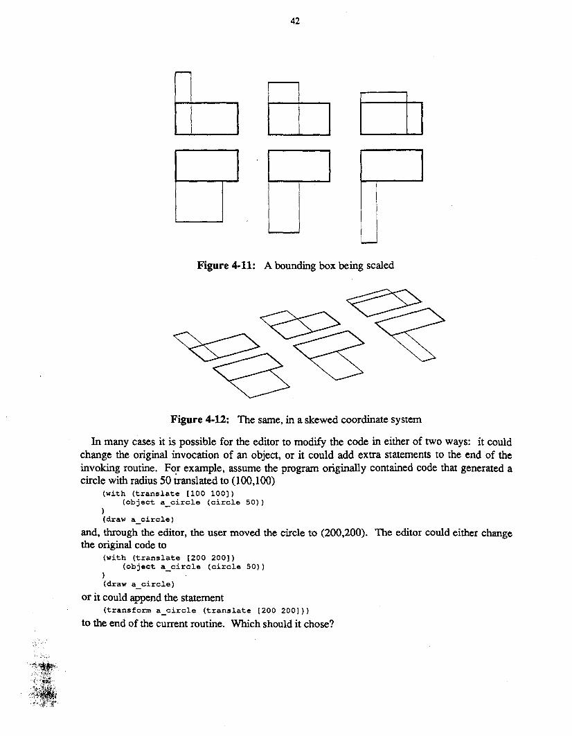
42
Figure 4-11: A bounding box being scaled
Figure 4-12: The same, in a skewed coordinate system
In many cases it is possible for the editor to modify the code in either of two ways: it couldchange the original invocation of an object, or it could add extra statements to the end of theinvoking routine. For example, assume the program originally contained code that generated acircle with radius 50 translated to (100,100)
(with (translate [100 100)(object a_circle (circle 50»
)(draw a_circle)
and, through the editor, the user moved the circle to (200,200). The editor could either changethe original code to
(with (translate [200 200)(object a_circle (circle 50»
)(draw a_circle)
or it could append the statement(transform a_circle (translate [200 200))
to the end of the current routine. Which should it chose?
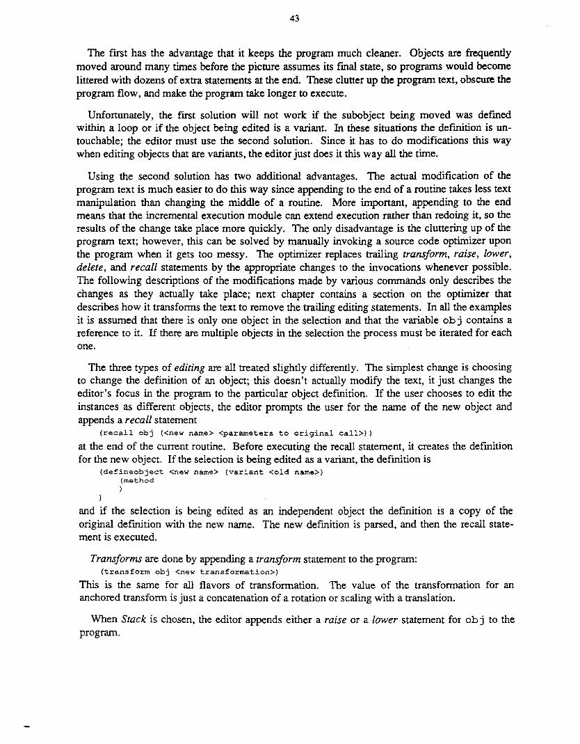
43
The first has the advantage that it keeps the program much cleaner. Objects are frequentlymoved around many times before the picture assumes its final state, so programs would becomelittered with dozens of extra statements at the end. These clutter up the program text, obscure theprogram flow, and make the program take longer to execute.
Unfortunately, the first solution will not work if the subobject being moved was definedwithin a loop or if the object being edited is a variant. In these situations the definition is untouchable; the editor must use the second solution. Since it has to do modifications this waywhen editing objects that are variants, the editor just does it this way all the time.
Using the second solution has two additional advantages. The actual modification of theprogram text is much easier to do this way since appending to the end of a routine takes less textmanipulation than changing the middle of a routine. More important, appending to the endmeans that the incremental execution module can extend execution rather than redoing it, so theresults of the change take place more quickly. The only disadvantage is the cluttering up of theprogram text; however, this can be solved by manually invoking a source code optimizer uponthe program when it gets too messy. The optimizer replaces trailing transform, raise, lower,delete, and recall statements by the appropriate changes to the invocations whenever possible.The following descriptions of the modifications made by various commands only describes thechanges as they actually take place; next chapter contains a section on the optimizer thatdescribes how it transforms the text to remove the trailing editing statements. In all the examplesit is assumed that there is only one object in the selection and that the variable ob j contains areference to it. If there are multiple objects in the selection the process must be iterated for eachone.
The three types of editing are all treated slightly differently. The simplest change is choosingto change the definition of an object; this doesn't actually modify the text, it just changes theeditor's focus in the program to the particular object definition. If the user chooses to edit theinstances as different objects, the editor prompts the user for the name of the new object andappends a recall statement
(recallobj «new name> <parameters to original call»)
at the end of the current routine. Before executing the recall statement, it creates the definitionfor the new object. If the selection is being edited as a variant, the definition is
(defineobject <new name> (variant <old name»(method)
)
and if the selection is being edited as an independent object the definition is a copy of theoriginal definition with the new name. The new definition is parsed, and then the recall statement is executed.
Transforms are done by appending a transform statement to the program:(transform obj <new transformation»
This is the same for all flavors of transformation. The value of the transformation for ananchored transform is just a concatenation of a rotation or scaling with a translation.
When Stack is chosen, the editor appends either a raise or a lower statement for ob j to theprogram.
44
The Copy operation requires the editor to come up with a name for the new object instance.This new name is then assigned the result of calling new on the original object with the appropriate transformation and the result is drawn:
(with <transformation of new object>(object <new name> (new obj»
)
(draw <new name»
Delete just appends a delete statement for obj.
Transform All is the one operation that cannot be done by appending statements since itoperates on paths as well as objects. It instead wraps the entire body of the routine in a withstatement
(with <transformation><original routine body>
)
and reexecutes the routine. Since this involves modification, not appending, it is impossible todo a Transform All on an object that is a variant of another object.
Add acts differently depending on whether the object to add already exists or is a totally newobject. If the latter, the editor prompts for the new name and creates a new skeleton defmitionfor the object:
(defineobject <new name>(method)
)
In either case the editor creates a new name for the instance and appends statements to theprogram to instantiate and draw the object to be added
(with <transformation of new object>(object <new name> «name of object> <parameters»)
)(draw <new name»
and executes the statements. If any control points were specified as parameters, the new code iswrapped with using statements for the objects involved. Finally, if a new type of object is beingadded, the editor shifts its focus to the new object so that the user can add subobjects to thenewly defmed object.
4.4. An extended exampleTo make all this more concrete, here is an extended example that uses most of the interesting
features of the Dee editor. Each step shows the changed section of the program as well as thepicture thus far produced. The part of the code added in each step is shown in boldface.
The user starts out with an empty program, shown in Figure 4-13. He then selects Add newfrom the menu, specifies that this new object is to be called car, and indicates the point (325,25)as the origin for the object using the mouse. Dee transforms the program as shown in Figure4-14. It creates a skeleton definition for the object car and adds an instantiation of car in themain program called a_car. 1O Since the definition of car is empty, the instantiation does not
IODee actually creates variables with uninformative names like object17. They have been changed in thisexample to add clarity.
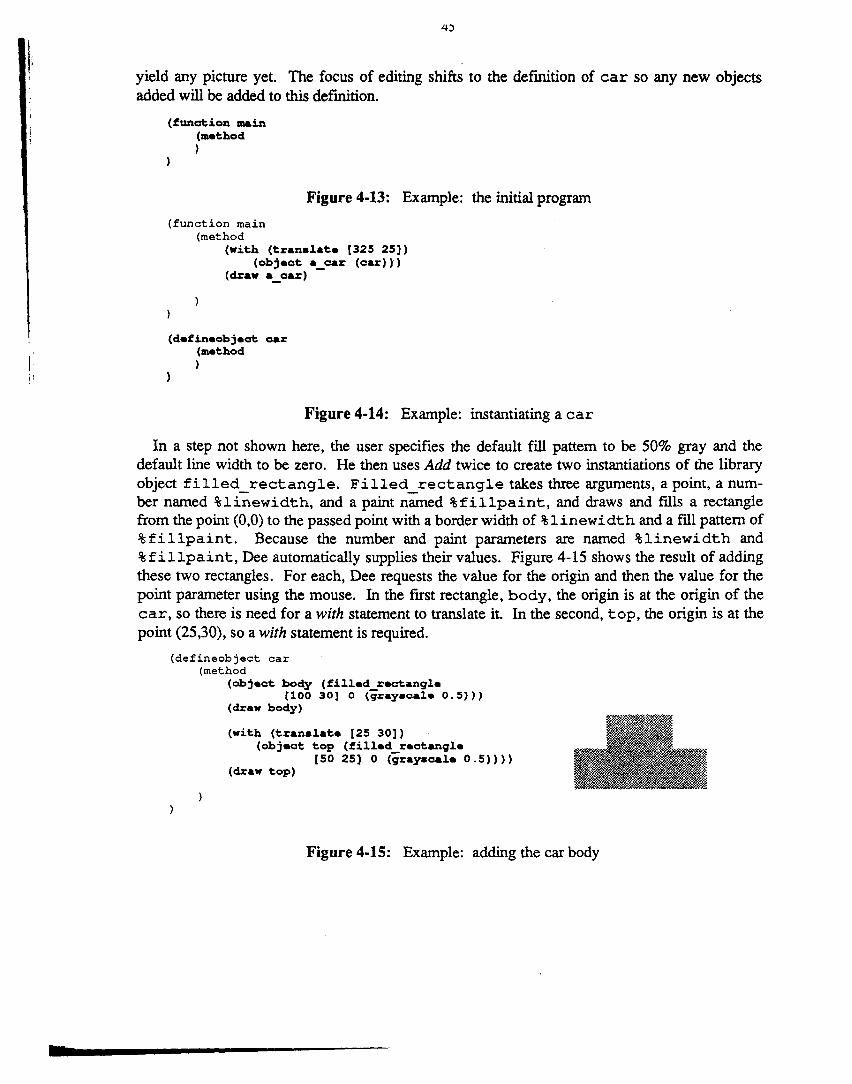
I·
•
yield any picture yet. The focus of editing shifts to the definition of car so any new objectsadded will be added to this definition,
(function main(meehod)
Figure 4-13: Example: the initial program
(function main(method
(wieh (eranalaee [325 25])(objeoe a oar (oar»)
(draw a_oar) -
(defineobjeoe oar(meehod)
Figure 4-14: Example: instantiating a car
In a step not shown here, the user specifies the default fill pattern to be 50% gray and thedefault line width to be zero. He then uses Add twice to create two instantiations of the libraryobject filled_rectangle. Filled_rectangle takes three arguments, a point, a number named %linewidth, and a paint named %fillpaint, and draws and fills a rectanglefrom the point (0,0) to the passed point with a border width of %linewidth and a fill pattern of%fillpaint. Because the number and paint parameters are named %linewidth and%fillpaint, Dee automatically supplies their values. Figure 4-15 shows the result of addingthese two rectangles. For each, Dee requests the value for the origin and then the value for thepoint parameter using the mouse. In the first rectangle, body, the origin is at the origin of thecar, so there is need for a with statement to translate it. In the second, top, the origin is at thepoint (25,30), so a with statement is required.
(defineobject car(method
(objeoe body (filled reoeangle[100 30] 0 (g~ay.oal. 0.5»)
(draw body)
(wieh (eranalaee [25 30])(objeoe eop (filled reaeangle
[50 25] 0 (grayaaale 0.5»»(draw eop)
Figure 4-15: Example: adding the car body
46
The user then changes the default to a white fill and a border width of one. In Figure 4-16 headds another rectangle, winl, using these values.
(defineobject car(method
(with (tran.late [31 31)(object win1 (filled rectangle
[17 20) 1 (gray.cale 1»»(draw win1)
Figure 4-16: Example: adding a window
Figure 4-17 shows the result of a new operation, Copy. Here the user copies winl to a newlocation; this location is specified by dragging the bounding box of winl to the new position(52,31). Dee creates the new instance by adding a call to new with winl as the argument andassigning the result to the variable win2.
(defineobject car(method
(with (tran.late [52 31)(object win2 (new win1»)
(draw win2)
Figure 4-17: Example: copying to make another window
In Figure 4-18 a similar process is used to add two circles for the tires. Thefilled_circle library object draws a circle around its origin though a specified point. Afterdrawing the wheels, the user clicks the Done button and the editing focus returns to the mainpicture.
(defineobject car(method
(with (tran.late [20 0])(object tire1 (filled circle
[0 10] 1 (gray.cale 0»»(draw tire1)
(with (tran.late [80 0])(object tire2 (new tire1»)
(draw tire2)
Figure 4-18: Example: adding wheels
47
The user then uses Copy twice to make two copies of the car; this is illustrated in Figure 4-19.The two copies are named 2nd_car and 3rd_ car.
(function main(method
(with (translate [325 25])(object a_car (car»)
(draw a_car)
(with (tranalate [325 100])(objeot 2nd oar (new a oar»)
(draw 2nd_oar) - -
(with (tranalate [325 175])(objeot 3rd oar (new a oar»)
(draw 3rd_oar) - -
Figure 4-19: Example: creating two more copies of the car
48
Figure 4-20 shows the result of selecting the middle instance, 2nd_car, and then clicking theEdit as variant button. Dee requests a new name for the variant, and when truck is entered itcreates a definition for truck as a variant car. 2nd car is then recalled to be a truck.Since the definition of truck is initially empty, the picture remains unchanged, but the editingfocus is now on truck.
(function main(method
(with (translate [325 25])(object a car (car»)
(draw a_car) -
(with (translate [325 100])(object 2nd car (new a car»)
(draw 2nd_car) - -
(with (translate [325 175])(object 3rd car (new 'a car»)
(draw 3rd_car) - -
(recall 2nd ear (truck»
(de£ineobject truck (variant car)(method)
Figure 4·20: Example: turning one copy into a truck
In Figure 4-21 the user makes two changes to the truck definition. He first deletes win2 andthen uses a Scale x transformation to change the size of the rectangle top. The original transformation of top, (translate [25 30]) is replaced by the new transformation (concat(translate [25 30]) (scale [0.6 1]». After making these changes, the useragain clicks Done and the focus returns to the main picture.
Next the user selects the top instance, 3rd car, and chooses Edit instance (Figure 4-22).The user supplies wagon as the new name and Dee creates a definition for wagon which is acopy of the definition for car and then adds a recall statement for 3rd_car. This is verydifferent from the change made to 2nd car: truck's definition is a variant of car's whilewagon's definition is a copy of it. Again the picture remains the same and Dee changes itsfocus to the new definition.
(defineobject truck (variant car)(method
(delete win2)(tranaform top (oonoat (tranalate [25 30])
(acale [0.61]»)
Figure 4-21: Example: editing the car to make it a truck(function main
(method(with (translate [325 25])
(object a car (car»)(draw a_car) -
(with (translate [325 100])(object 2nd car (new a car»)
(draw 2nd_car) - -
(with (translate [325 175])(object 3rd car (new a car»)
(draw 3rd_car) - -
(recall 2nd car (truck»(reoall 3rd-car (wagon»
(defineobject wagon(method
... copy of code for car
7
Figure 4-22: Example: turning another copy into a wagon
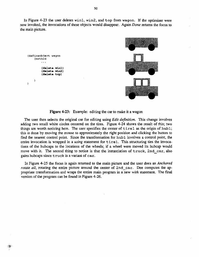
50
In Figure 4-23 the user deletes winl, win2, and top from wagon. If the optimizer werenow invoked, the invocations of these objects would disappear. Again Done returns the focus tothe main picture.
(defineobject wagon(method
(delete winl)(delete win2)(delete top)
Figure 4-23: Example: editing the car to make it a wagon
The user then selects the original car for editing using Edit definition. This change involvesadding two small white circles centered on the tires. Figure 4-24 shows the result of this; twothings are worth noticing here. The user specifies the center of tirel as the origin of hubl;this is done by moving the mouse to approximately the right position and clicking the button tofind the nearest control point. Since the transformation for hubl involves a control point, theentire invocation is wrapped in a using statement for tirel. This structuring ties the invocations of the hubcaps to the locations of the wheels; if a wheel were moved its hubcap wouldmove with it. The second thing to notice is that the instantiation of truck, 2nd_car, alsogains hubcaps since truck is a variant of car.
In Figure 4-25 the focus is again returned to the main picture and the user does an Anchoredrotate all, rotating the entire picture around the center of 2nd_car. Dee computes the appropriate transformation and wraps the entire main program in a new with statement. The finalversion of the program can be found in Figure 4-26.

51
(defineobject car(method
(u.ing t.ire1(wit.h (t.ran.lat.e (get.point. t.ire1 cent.er»
(Object. hub1 (~illed_circle
[0 S] 0 (gray.cale 1»»(draw hub1)
(u.ing t.ire2(wit.h (t.ran.lat.e (get.point. t.ire2 cent.er»
(object. hub2 (new hub1»)(draw hub2)
Figure 4-24: Example: adding hubcaps to the car
(function main(method
(wit.h (concat. (t.ran.lat.e [766.46 137.247])(rot.at.e 165»
(with (translate [325 25])(object a car (car»)
(draw a_car) -
(with (translate [325 100])(object 2nd car (new a car»)
(draw 2nd_car) - -
(with (translate [325 175])(object 3rd car (new a car»)
(draw 3rd_car) - -
(recall 2nd car (truck»(recall 3rd-car (wagon»
Figure 4-25: Example: rotating.the entire picture
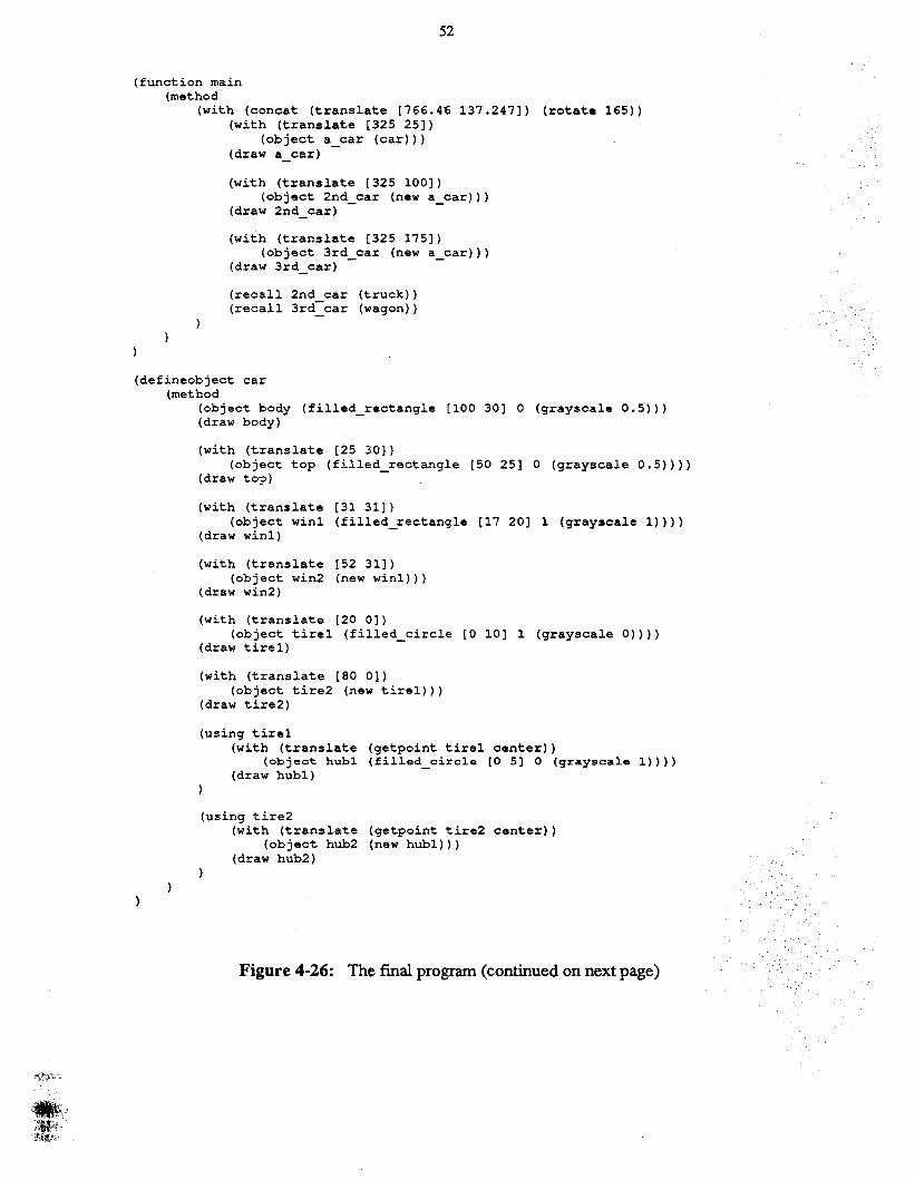
52
(function main(method
(with (concat (translate [766.46 137.247) (rotate 165»(with (translate [325 25)
(object a car (car»)(draw a_car) -
(with (translate [325 100])(object 2nd car (new a car»)
(draw 2nd_car) - -
(with (translate [325 175])(object 3rd car (new a car»)
(draw 3rd_car) - -
(recall 2nd car (truck»(recal13rd-car (wagon»
(defineobject car(method
(object body (filled_rectangle [100 30) 0 (grayscale 0.5»)(draw body)
(with (translate [25 30])(object top (filled rectangle [50 25) 0 (grayscale 0.5»»
(draw top) -
(with (translate [31 31])(object win1 (filled_rectangle [17 20) 1 (grayscale 1»»
(draw winl)
(with (translate [52 31])(object win2 (new win1»)
(draw win2)
(with (translate [20 0])(object tire1 (filled circle [0 10) 1 (grayscale 0»»
(draw tirel) -
(with (translate [80 0)(object tire2 (new tire1»)
(draw tire2)
(using tire1(with (translate (getpoint tirel center»
(objeot hubl (filled_circle [0 5] 0 (grayscale 1»»(draw hubl)
(using tire2(with (translate (getpoint tire2 center»
(object hub2 (new hubl»)(draw hub2)
Figure 4-26: The fmal program (continued on next page)
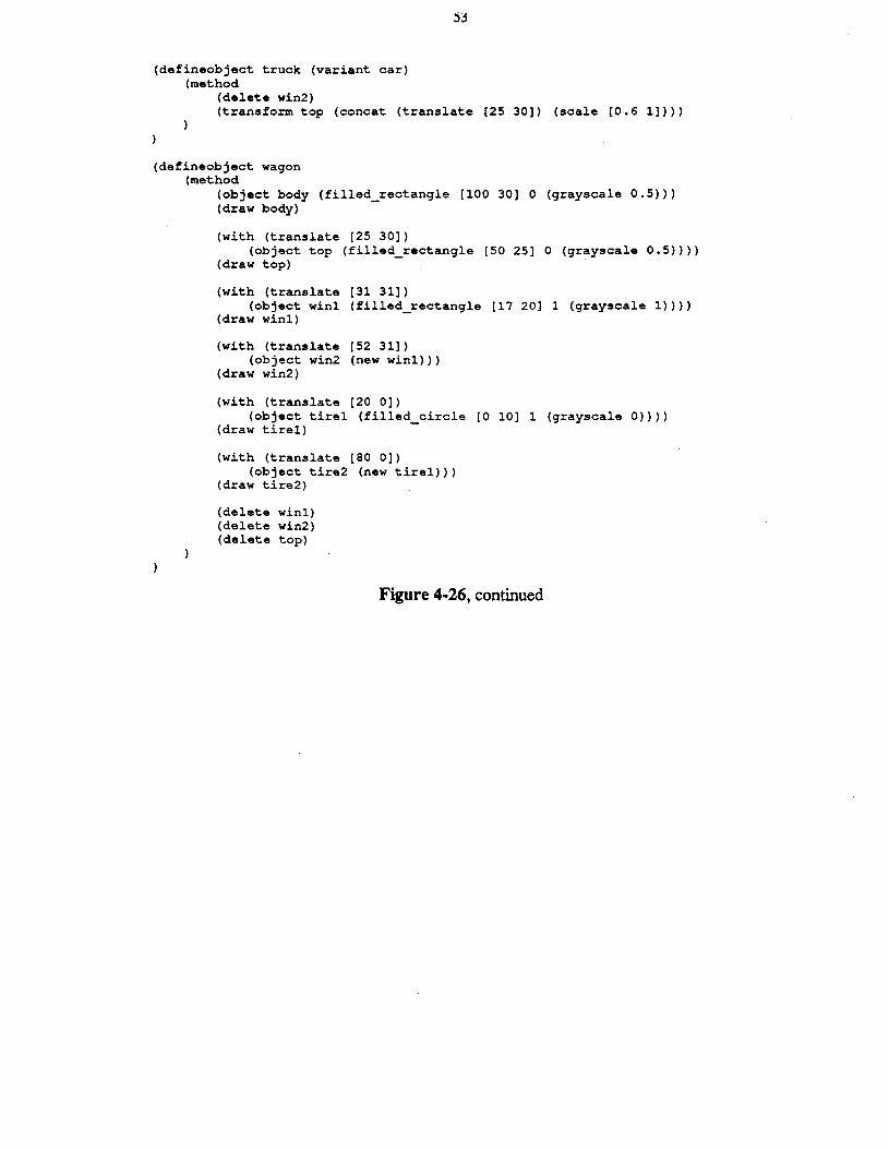
(defineobject truck (variant car)(method
(delete win2)(transform top (concat (translate [25 30]) (scale [0.6 1]»)
(defineobject wagon(method
(object body (filled_rectangle [100 30] 0 (grayscale 0.5»)(draw body)
(with (translate [25 30])(object top (filled rectangle [50 25] 0 (grayscale 0.5»»
(draw top) -
(with (translate [31 31])(object win1 (filled_rectangle [17 20] 1 (grayscale 1»»
(draw win1)
(with (translate [52 31])(object win2 (new win1»)
(draw win2)
(with (translate [20 0])(object tire1 (filled circle [0 10] 1 (grayscale 0»»
(draw tire1) -
(with (translate [80 0])(object tire2 (new tire1»)
(draw tire2)
(delete win1)(delete win2)(delete top)
Figure 4-26, continued

54
5. ImplementationThis chapter covers details of Dee's implementation. Dee consists of about 14,500 lines of C
code, 200 lines of MLisp [13] to streamline the editor interface, 500 lines of Dum code toprovide the default object library, and 600 lines of PostScript [l] for generating hard copy. Deeuses the X Window System [12] as its graphics support.
Since Dee contains an interpreter, there is potential confusion between the Dum language itinterprets and the C language used to implement it. This is particularly severe when talkingabout how data is stored, since some things are stored as Dum types and some are stored as Ctypes. To avoid confusion, I will use the following conventions when talking about datarepresentation:
Number always refers to a Dum number.Integer andfloat always refer to C types.Array always refers to a Dum array.List always refers to a C array.Linked lists will always be qualified as such.
In addition, all unions mentioned are discriminated.
5.1. OverviewFigure 5-1 shows the basic structure of Dee. The program text is parsed to produce a parse
tree and a symbol table; these in tum are interpreted by the interpreter, creating a history of theexecution called the execution tree, a set of object instances, and a display tree representing thestructure of the picture. The display module combines the display tree with the object instancesto produce a picture upon the display. When the user requests a change to the picture, thegraphics editor uses the display tree and the symbol table to construct the appropriate modification to the program.
5.2. ParsingDee parses a program using two passes. The input file is first preparsed into a linked list
containing tokens and sublists. There are three kinds of tokens: numbers, strings, and names.Numbers and strings represent constants of the appropriate type, and names represent variables,routine names, and keywords. Lists are either norma1lists, containing one or more elements, orpoint expressions, containing exactly two elements. This pass performs no name lookup; it justtranslates the program text into a linked list representation.
A simple recursive descent parser then makes another pass over the resulting parse tree. Thispass replaces names with symbol table pointers and checks the structure of all the language constructs. Because Dum's polymorphic arrays require run-time type checking, the parser doesnone other than verifying that expressions are used wherever they are required by the languagesyntax.
Dee maintains a hashed global symbol table containing keywords, subroutine names, and control point names. Since different objects can have control points with the same names, the namesstored in the table have the object name and a "$" concatenated to the name; for example, thetop control point of the box object would be stored as box$top. Each symbol table entry for
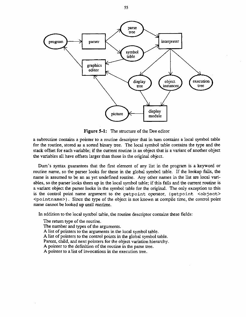
55
Figure 5-1: The structure of the Dee editor
a subroutine contains a pointer to a routine descriptor that in turn contains a local symbol tablefor the routine, stored as a sorted binary tree. The local symbol table contains the type and thestack offset for each variable; if the current routine is an object that is a variant of another objectthe variables all have offsets larger than those in the original object.
Dum's syntax guarantees that the first element of any list in the program is a keyword orroutine name, so the parser looks for these in the global symbol table. If the lookup fails, thename is assumed to be an as yet undefmed routine. Any other names in the list are local variables, so the parser looks them up in the local symbol table; if this fails and the current routine isa variant object the parser looks in the symbol table for the original. The only exception to thisis the control point name argument to the getpoint operator, (getpoint <object><pointnarne». Since the type of the object is not known at compile time, the control pointname cannot be looked up until runtime.
In addition to the local symbol table, the routine descriptor contains these fields:
The return type of the routine.The number and types of the arguments.A list of pointers to the arguments in the local symbol table.A list of pointers to the control points in the global symbol table.Parent, child, and next pointers for the object variation hierarchy.A pointer to the definition of the routine in the parse tree.A pointer to a list of invocations in the execution tree.
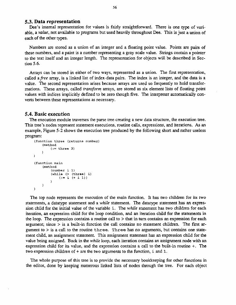
56
5.3. Data representationDee's internal representation for values is fairly straightforward. There is one type of vari
able, a value, not available to programs but used heavily throughout Dee. This is just a union ofeach of the other types.
Numbers are stored as a union of an integer and a floating point value. Points are pairs ofthese numbers, and a paint is a number representing a gray scale value. Strings contain a pointerto the text itself and an integer length. The representation for objects will be described in Section 5.6.
Arrays can be stored in either of two ways, represented as a union. The first representation,called afree array, is a linked list of index-data pairs. The index is an integer, and the data is avalue. The second representation arises because arrays are used so frequently to hold transformations. These arrays, called transform, arrays, are stored as six element lists of floating pointvalues with indices implicitly defined to be zero though five. The interpreter automatically converts between these representations as necessary.
5.4. Basic executionThe execution module traverses the parse tree creating a new data structure, the execution tree.
This tree's nodes represent statement executions, routine calls, expressions, and iterations. As anexample, Figure 5-2 shows the execution tree produced by the following short and rather uselessprogram:
(function three (returns number)(method
(:= three 3)
(function main(method
(number i 1)(while (> (three) i)
(:= i (+ i 1))
The top node represents the execution of the main function. It has two children for its twostatements, a datatype statement and a while statement. The datatype statement has an expression child for the initial value of the variable i. The while statement has two children for eachiteration, an expression child for the loop condition, and an iteration child for the statements inthe loop. The expression contains a routine call to > that in tum contains an expression for eachargument; since> is a built-in function the call contains no statement children. The first argument to > is a call to the routine three. Three has no arguments, but contains one statement child, an assignment statement. This assignment statement has an expression child for thevalue being assigned. Back in the while loop, each iteration contains an assignment node with anexpression child for its value, and the expression contains a call to the built-in routine +. Thetwo expression children of + are the two arguments to the function, i and 1.
The whole purpose of this tree is to provide the necessary bookkeeping for other functions inthe editor, done by keeping numerous linked lists of nodes through the tree. For each object
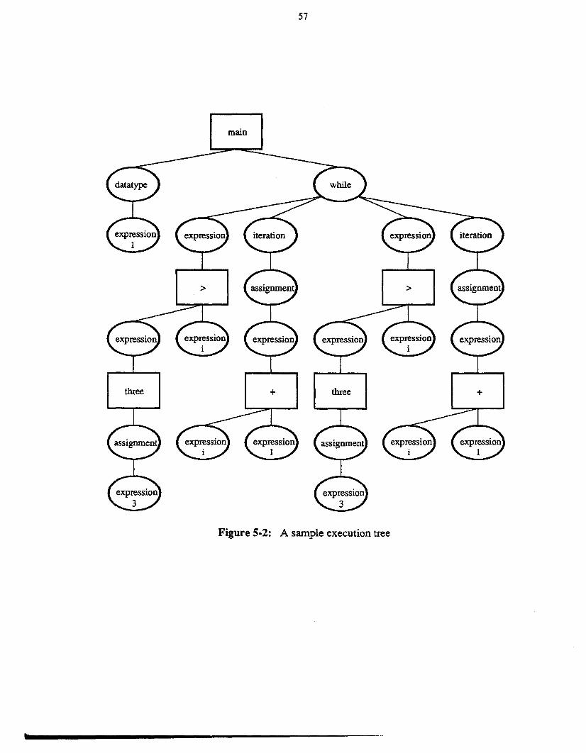
57
main
three + three +
t
Figure 5-2: A sample execution tree
58
type, Dee maintains a linked list of instantiations, and for each object instance, it maintains alinked list of all using statements for that object and a linked list of all using statements forobject arguments within the execution of the object. The node for a using statement containssome extra information: a copy of the current routine's stack frame, the current graphical transformation, and the state of the current path; these allow the interpreter to restore the programstate before reexecuting the using statement.
5.5. Paths and the display treeA path is maintained as a recursive data structure, each instance containing whether or not the
path is to be filled, the border width, the fill paint, the path's bounding box, and a linked list ofpath components. Path components can be simple path construction operators like moveto,lineto, and arc, subpaths, transformation pushes and pops, drawn objects, or start and end marks.
When the interpreter begins execution of the main program, it creates a new empty path. Asthe program executes, various path components get linked into the current path. Drawpath andfillpath statements create subpaths, statements like moveto and lineto statements add the corresponding path components, and with adds a transformation push and pop. Each invocation ofan object creates a new empty path, and statements within the object definition add componentsto this path. Drawing an object links its path into the current path. Start and end marks areadded by the using statement to delineate the section of the path created by code within theusing.
The final top-level path is called the display tree. This is used to draw the picture, both initially and when the window system notifies Dee that it needs to refresh its picture window. Thistree is also used by the graphics editor interface to find objects pointed to by the mouse.
5.6. Objects and inheritanceAn object value consists of a pass count, described later, and a pointer to an object descriptor.
This descriptor contains the following information:
The transformation in effect when the object was created.The pass count when the object was drawn.The head of the using chain for the object.The head of the using chain in the object.The object's bounding box relative to its parent object.A pointer to the object creating this object.A pointer to the arguments in the instantiation call.A pointer to an object low-level descriptor.
The low-level descriptor in tum contains
The object's path.A pointer to the object's routine descriptor.A list of values of the object's control points.The final values of the object's local variables.
The reason for this distinction is that the low-level descriptor contains all the information common to multiple copies of the object, while the object descriptor contains the information thatdiffers for each copy. When one object is created from another using new, the created objectgets a new object descriptor, but shares the original object's low-level descriptor.

59
This sharing can potentially save an enormous amount of time and storage. Figure 5.6 showsthe familiar recursive snowflake curve, this time only expanded to two levels, and below it thestructure of its display tree. Here the rectangles represent paths, and the ellipses components ofthe path. The display is represented as a path with three components, each a side object. Sincethe second and third objects were created by calls to new rather than by direct calls to side, thethree objects share the low-level descriptor with the path for the side. This call to side is with thearguments 0, for the current depth, and 2, for the maximum depth. The definition of side callsitself recursively with an increased depth parameter, (side 1 2), and calls new with theresult three times to create the four segments of the side. They again share a low-level descriptor, and the process recurs until the depth parameter is equal to the maximum parameter, (side2 2). In this case side just draws a simple line segment.
Without the path sharing, this structure would be a very bushy tree. Dee can compute anddraw the snowflake expanded to three levels in 2 seconds using 61 kilobytes of data storage. Ifthe program is rewritten without new, the same picture requires 9 seconds and 1023 kilobytes ofstorage. Expanding the snowflake to four levels requires 10 seconds and 151 kilobytes usingnew and cannot be drawn without running out of virtual memory without new.
Text objects are created using a built-in function, text, that returns an object reference. Thelow-level descriptor for a text object contains a string and a font instead of a path.
When an object is linked into a path, a reference to the object descriptor is put in the pathcomponent. This means that object descriptors must stay around, even if no variables in theprogram refer to them. Objects may also be multiply referred to if one object variable is assigned to another. These facts make it rather difficult to determine exactly when object descriptors should be deallocated. To simplify things, all object descriptors and low-level descriptorsare kept in linked lists and deallocated only before a program is fully executed.
Whenever the interpreter executes an object definition it creates a stack frame to hold thedefinition's variables. The frame is a list of values (recall that a value is the union of all othertypes); having each entry be the same size simplifies addressing. If the object being executed isa variant of another object, the frame is large enough to hold the variables of both the originaland the variant objects. Before executing the variant definition the interpreter executes thedefinition of the original using the variant's stack frame. Since, as described above, the variablesin the variant all have offsets different from those in the original, the variant can use both its ownvariables and the variables of the original.
5.7. Display and funargsThe display module generates the picture through a simple traversal of the display tree. When
it encounters an object, it must convert the object's relative position to an absolute position. Todo this it maintains a stack of transformations; each stack entry contains both the new transformation and the cumulative product of all transformations thus far.
As mentioned in Chapter 3, funarg problems arise with transformations whenever an objectgets drawn by an object other than the one that created it. Since objects can only be passed downas parameters, not up as return values, the creator's transformation must be on the transformstack somewhere. The display module needs to find this transformation and make a branch in
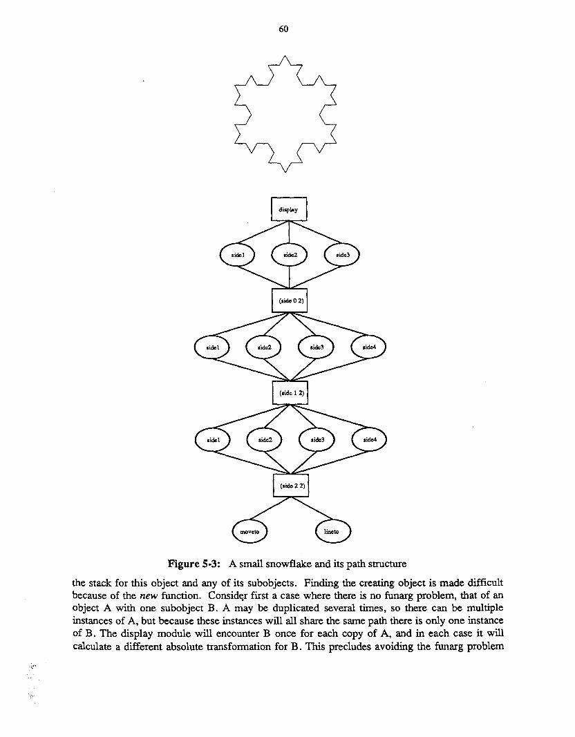
60
Figure 5-3: A small snowflake and its path structure
the stack for this object and any of its subobjects. Finding the creating object is made difficultbecause of the new function. Consider first a case where there is no funarg problem, that of anobject A with one subobject B. A may be duplicated several times, so there can be multipleinstances of A, but because these instances will all share the same path there is only one instanceof B. The display module will encounter B once for each copy of A, and in each case it willcalculate a different absolute transformation for B. This precludes avoiding the funarg problem
61
completely by using stored absolute transformations, This also precludes the use of any funargsolution that involves maintaining and following a parent pointer to the creating object, since anobject's parent is not unique.
What Dee does is maintain a pass count for each object. This count tells how many levelsseparate the current location of the object from its creator's frame. When an object is passed as aparameter, the count is incremented, and when the routine to which it was passed returns thecount is decremented. The pass count is copied into the object descriptor when the object isdrawn. This saved count tells the display module how many transformation stack entries it mustskip before it finds the entry for the creating object.
The pass count is also used by the interpreter to calculate the value of control points. Recallthat the value of a control point is the value assigned within the object definition, transformed byobject's transformation, and then inversely transformed by the current transformation, The difficulty occurs when an object has been passed; in this case the calculation must invert the currenttransformation relative to the object that created the control point's object. An example maymake this clearer. Consider the following objects:
(defineobject a(control p)(method
(::p[OO])
(defineobject b (args (object 0»(method
(with (translate [5 5])(print (getpoint 0 p»)
(defineobject c(method
(with (translate [10 10])(object A (a»)
(with (translate [100 100])(object B (b A»
)
Here object a defines one control point, p, and gives it the value [0 0]. Object b takes anobject 0 as an argument, and prints the value of its control point p under a translation of [5 5].Object c instantiates an a translated by [10 10 ] , and then passes the result to b with a translation of [100 100]. The value of the control point p relative to c (c itself could be instantiated with any transformation) is [10 10], so the value of the control point when it is printedis [- 95 - 95]. In order to calculate this the interpreter must take into account not only thecurrent transformation in b, (translate [5 5]), but also the transformation of b in c,(t rans 1 ate [ 1 00 1 0 0 ] ). It does this by keeping the same sort of transformation stack as
the display module and using the pass count to determine how many transformations must beconsidered to find the current transformation.
62
5.8. The using statementWhen an object is transformed, the interpreter must reexecute all using statements that depend
upon the object's location. These consist of all using statements for the object being moved, aswell as all using statements in the object for objects that were passed to it as parameters. Theseusings are found by following the two using chains stored in the object descriptor. There areseveral steps involved for each using statement; this section will call the object that is the subjectof the using statement the used object, and the object whose definition contains the using statement the containing object.
The interpreter first frees the part of the execution tree below the using statement's node. Thismay delete other using statements; the interpreter must take care to remove these from theirusing chains. When the using was first executed it placed a start mark in the display tree beforeexecuting any subordinate statements .and placed an end mark afterwards. By consultingpointers to these marks within the using node, the interpreter deletes any portion of the displaytree created by statements within the using.
At this point all results of the original execution have been deleted. The interpreter nowrecreates the environment that was in effect when the using was first executed. The using nodecontains a copy of the current stack frame when the using was first executed, a pointer to thecurrent path, and the current transformation. These all temporarily replace the values of thecorresponding variables in the interpreter state. If the used object was passed to the containingobject, the interpreter has to do some extra work. Any calculations of control point values require taking into consideration the transformations of ancestors of the containing object, so thesetransformations must be put onto the stack before the stored current transformation. In order tofind these transformations the interpreter follows the parent pointer in the containing object'sdescriptor and uses the stored transformations in the descriptors found along the way; the passcount tells how far the parent chain must be followed. This parent pointer is not usually accurate, as described in the previous section, since calling new for an object creates multipleparents for all of the object's subobjects, but recall that new actually does a call when copying anobject that was passed any objects as arguments. The parent pointer is correct in this one instance, and this is precisely when it is needed for using.
Once the environment has been reestablished, the interpreter reexecutes the code in the usingstatement. This reexecution may include new using statements; the interpreter makes sure theseget put into the using chains ahead of the using currently being reexecuted to avoid needlessreexecution.
5.9. Incremental parsingWhen the user makes changes to the textual representation of the picture Dee must determine
just what has been changed and alter the parse tree appropriately. Some window systems [23]provide the tools needed to do this easily; unfortunately X [12] does not. Building the propertools would have been a time-consuming process clearly irrelevant to the research issues inTweedle.
Dee runs a subprocess of Emacs [13] and communicates to it using Unix's interprocess communication mechanisms. When the user asks Dee to do the changes to the text, Dee has Emacscopy the program into a temporary file. Dee then parses this changed file and compares the new
63
and the old parse trees to determine where the changes occur. This technique, clumsy as it is,works acceptably well in practice and has the advantage of basing the results upon changes to theparse tree rather than changes to the text of the program. The user can add or change commentsor indentation, or can change a variable's name, and when the changes get executed the comparison module will report that no changes were made, causing no reexecution to take place.
5.10. Incremental executionAs discussed in Section 4.1, there are four different possibilities in incremental execution.
Some objects may need reexecution, some objects may need extension, the main program mayneed extension, and the main program may need full reexecution. The final possibility is easy,the other three are more complicated.
If an object needs reexecution, the interpreter redoes each execution in the invocation chain.For each one, the statements in the execution and the components in the object's path are freed.The argument values stored in the object descriptor initialize the parameters, and the body of theobject is executed. After this, the interpreter reexecutes all using statements for the object asdescribed in the previous section.
When objects are extended, the stored final values of the stack frame are used to reestablishthe state at the end of the object's execution, then the newly added code is executed. As in theprevious case the interpreter reexecutes the appropriate using statements, and the new finalvalues replace the previous ones.
Extending the main program is quite simple; the interpreter just maintains the main program'sfinal stack frame between executions.
When an object with variants is changed the interpreter must also reexecute any invocations tothe variant objects. A possible problem occurs if the changed original object definition has newvariables added, since the original's variables' offsets now conflict with the offsets of thevariant's variables. The most common case for this to occur is when the original object getsextended, and the problem solves itself then. The interpreter assigns offsets in the order that thevariables occur in the program text, so the only conflicts that occur are between the new variables and the variables in the variant. If the variant definition is unchanged, it cannot refer tothese new variables, and the original's variables and the variant's variables peacefully coexist inthe stack frame since all stack frame entries are the same size. If the variant defmition uses thesevariables, it must have changed too, so it will have been reparsed with new, nonconflicting offsets for its variables.
In the other case, the new variables were added internally to the original definition. This willcause some of the old variables to have larger offsets, and some of these will conflict with thosein the variant. Moreover, the variant can use these variables, so it would have two variablesavailable to it with the same offset. When this occurs, the interpreter forces all the variants to bereparsed and thereby gain new variable offsets.
64
5.11. Display and graphics editorThe display module calculates bounding boxes for objects as it traverses the tree. These
bounding boxes are used by the editor to determine which object the user is pointing to when heattempts to a selection. The editor maintains a current path pointer into the display tree, andwhen the user makes a selection it looks through the components of the current path to find theappropriate object. If the user clicks the mouse multiple times without moving the mouse, thecomponents are searched starting with the last object found, and if another object is foundbeneath the cursor it replaces the last object in the selection. This allows the selection of objectsthat are obscured by other objects in the display. If the user edits the selected objects, theeditor's current path pointer is moved to the object's path.
Every element in the picture is not necessarily selectable; in particular output generatedthrough the direct use of paths cannot be selected. There must also be some variable in thecurrent routine that refers to the object at the end of the routine. This restriction is not normallya problem since the editor creates new object variables for each object it creates. The onlyproblems can occur in user-written code; for example, object creations passed directly to drawstatements, as in
(draw (rectangle»
cannot be selected. The interpreter will fmd object references even if they are stored in arrays,so programs can create editable objects in loops by storing their references in an array.
A more severe restriction is that the user cannot select objects that were created within usingstatements. The problem with these objects is that they are defined within the program to have aparticular relationship with other objects; if, for example, an arrow is drawn connecting twoboxes the semantics of getpoint and using guarantee that the arrow is guaranteed to connect thecorrect points, no matter how the boxes move or change. If the user moves the arrow and thenmoves one of the boxes, the reexecution of the using statement would cause the change to thearrow to be undone. Just what the appropriate behavior here should be is rather unclear; thissolution has the advantage of being at least consistent. In practice this requires the user to dividethe elements of picture into two classes, editable objects and subordinate objects that connectthem. For most pictures this division causes no problems, but for others it is rather contrived.
The editor generates new code in response to user input in the form of a text string, which isinserted into the program text at the correct place. The editor calls the preparser to translate thestring into a linked list and then passes this list on to the parser. The parser inserts the new codeinto the parse tree at the appropriate place and then parses it, and finally editor invokes the incremental execution module on the changed routine defmitions.
5.12. Display optimizationWhenever the display tree for a program changes, the editor must update the window contain
ing the current picture. The current implementation always fully redraws the picture in responseto these changes, but there are several possible optimizations not implemented because of timepressure. These are display coordinate caching, incremental bounding box calculations, and incremental redisplay.
65
5.12.1. Display coordinate cachingThe editor display module always has to draw changed portions of a picture, but is sometimes
must also redraw unchanged portions. This occurs very frequently in the current full redisplayscheme, but will also occur in optimized schemes when the window containing the picture isuncovered by the window system or when the display module has to patch up newly exposedparts of the drawing in response to a user change. Each redisplay transforms the relative coordinates stored in the display tree into the absolute display coordinates required by the windowsystem. Caching these absolute coordinates can make this redisplay more efficient.
Any caching scheme is complicated by the fact that the display tree is not really a tree butrather a directed acyclic graph. If an object is copied with new its path appears only once in thetree even though it appears multiple times in the drawing. The following caching method onlysaves the display coordinates for one instance of the shared part of the tree; it could easily beextended to save any fixed number of instances by sacrificing storage in the non-shared case.
The tree traversal can tell which parts of the tree it has encountered before by tagging eachtree entry as it encounters it. This tagging must uniquely identify each traversal; a simple twostate tag will not suffice since each traversal will not necessarily visit each node in the tree.Further, altering the display will cause some nodes to be marked as changed, and the cachedinformation in these nodes will be out of date. There are thus four possible cases to consider foreach node:
1. Marked as changed, tag not equal to current tag: The cached information isobsolete, and this is the first time the traversal has encountered this node. Recalculate the display coordinates, cache them, and tag this node with the current tag.
2. Marked as changed, tag is equal to current tag: This node has been encountered before, so its cached values do not apply to this visit. Calculate the displaycoordinates and use them.
3. Not marked as changed, tag not equal to current tag: The cached informationis still valid and applies to this visit. Use the cached coordinates and tag this nodewith the current tag.
4. Not marked as changed, tag is equal to current tag: This node has been encountered before, so its cached values do not apply to this visit. Calculate the display coordinates and use them.
This caching will save some execution time, but it-may not make the picture display morequickly. A moderately complicated picture like Figure 5-2 takes about 2 seconds of real timeand 1 second of execution time to display. Profiling reveals that between 5 and 10 percent of theexecution time is spent performing matrix multiplications and coordinate transformations, so thebenefits of caching would be slight. Nonetheless, it requires very little extra storage and thesoftware overhead for maintaining a cache is very small, so it would be a worthwhile addition.
5.12.2. Incremental bounding box calculationsBounding boxes are used by the editor to resolve mouse hits and by the incremental redisplay
algorithm described in the next section to determine what parts of the picture need to beredisplayed. Changing the picture will cause some of the bounding boxes to change.
66
An objects' bounding box is the smallest rectangle containing the bounding boxes of its subobjects and paths. When an object is moved, added, or deleted the bounding boxes of all itsancestor objects may change. These changes can be carried out by a two pass algorithm: firstinformation about what boxes need recalculation propagates up the display tree, then a secondpass downward performs all these calculations.
Because of path sharing with new and object connection with control points, a single editingoperation can affect many different objects throughout the display tree. Were this not the case, asingle pass up the tree would suffice, but when multiple changes occur this approach can resultin calculating bounding boxes for some objects multiple times. By doing two passes this extrawork is avoided. Here is the bounding box algorithm:
1. For each changed object, mark it and its ancestors as needing recalculation all theway up the tree to the root. If a node that is already marked is encountered, stop;all its ancestors will already be marked.
2. Traverse the tree. At each node, recompute the bounding boxes of all markedchildren by recursively applying this procedure; then set the current bounding boxto include the boxes of all children.
During this bounding box calculation, the cached display coordinates can be used and updated.
5.12.3. Incremental redisplayThe biggest potential perfomance gain comes from incremental redisplay, since only the parts
of the picture that need redrawing are sent to the window system. This algorithm requiresbounding regions for both the old and the new locations of an object; if an object is added to thepicture its old bounding region is null and if it is deleted from the picture the new boundingregion is null.
The bounding regions used by this algorithm could be either simple bounding boxes or shapesthat fit the object more closely. Closer approximations to the true shape of an object will requireless patching up of the picture, but the union and intersection calculations on regions will become more complex. The optimum balance to achieve fastest redisplay will depend upon therelative speeds of calculation and drawing in a particular system.
This algorithm relies on the ordered organization of the display tree, with the leftmost childrenof a node being drawn first and being overlapped by the children to the right of it.
1. Set up two clipping regions on the picture window, OLD and OLD+NEW. OLD is theunion of the previous bounding regions of all changed objects, and OLD+NEW is theunion of the previous bounding regions and the new bounding regions.
2. Fill the OLD region with the background pattern. This erases the previous objects.
3. Construct a line of nodes through the tree through the leftmost chain of nodes froma changed object to the root. Continue this line to a leaf node, always followingthe leftmost child. This line divides the tree in two parts, those nodes lower in thestacking hierarchy than any changed objects and those nodes at least as high in thishierarchy as the lowest changed object.

67
4. Do a preorder traversal of the tree:
• If a node is to the left of the dividing line, check if its bounding region intersects the OLD region.
• If the node is a leaf and intersects OLD, draw it using OLD as a clippingregion. If it is a leaf and does not intersect OLD, ignore it; it does notneed drawing.
• If the node is not a leaf and does not intersect OLD, ignore the node'schildren; they do not need drawing. If it does, apply the same criteriato each of the node's children.
• If a node is on the dividing line or to the right of it, do the same except useOLD+NEW as the testing and clipping region. Any recursive applicationsshould be tested against the appropriate region depending upon whether thechild is to the left or the right of the dividing line.
Figure 5-4 shows this at work. Figure 5-4a shows the display tree for Figure 5-4b just beforethe central box is moved to the position shown by the hollow square. Each of the five children inthe tree is shaded the same as the corresponding box in the picture. The OLD region is themedium shaded area, and the OLD+NEW region is that plus the area in the hollow box. Figure5-4c shows the display after OLD is filled with the background pattern. The dividing line isconstructed next, going from the center child node up through the root node.
The display tree now gets traversed. The root node is on the dividing line, so all of its childrenare examined. The leftmost child is to the left of the dividing line and intersects OLD, so the partof it in OLD is redrawn, yielding Figure 5-4d. The next node is also to the left of the line but itdoesn't intersect OLD, so nothing happens. The third node is the moved object. It is on the lineand intersects OLD+NEW, so it is redrawn in OLD+NEW giving Figure 5-4e. The last two nodesare each compared to OLD+NEW, each intersects it, and so they are redrawn clipped to OLD+NEW,
Figures 5-4f and 5-4g.
The effect of this algorithm is to compare all objects in the tree against the OLD region; anyintersecting it need redisplay because filling the background pattern will have erased them. Anyobjects in the tree to the right of the dividing line should overlap the redrawn object, so they arealso compared to the NEW region by comparing them with OLD+NEW.
5.13. Relative transformationsWhen the user moves an object in the editor, the result is a transformation relative to the
object's current location. The transform statement requires an absolute transformation; howshould the relative transformation be converted to an absolute one? Four solutions come tomind.
The original transformation of the object is stored in the object descriptor; use(concat <object's transform> <new transform»
as the transformation in the transform statement. Unfortunately the object's transformation isjust stored as an array; inserting this into the program text is unenlightening.
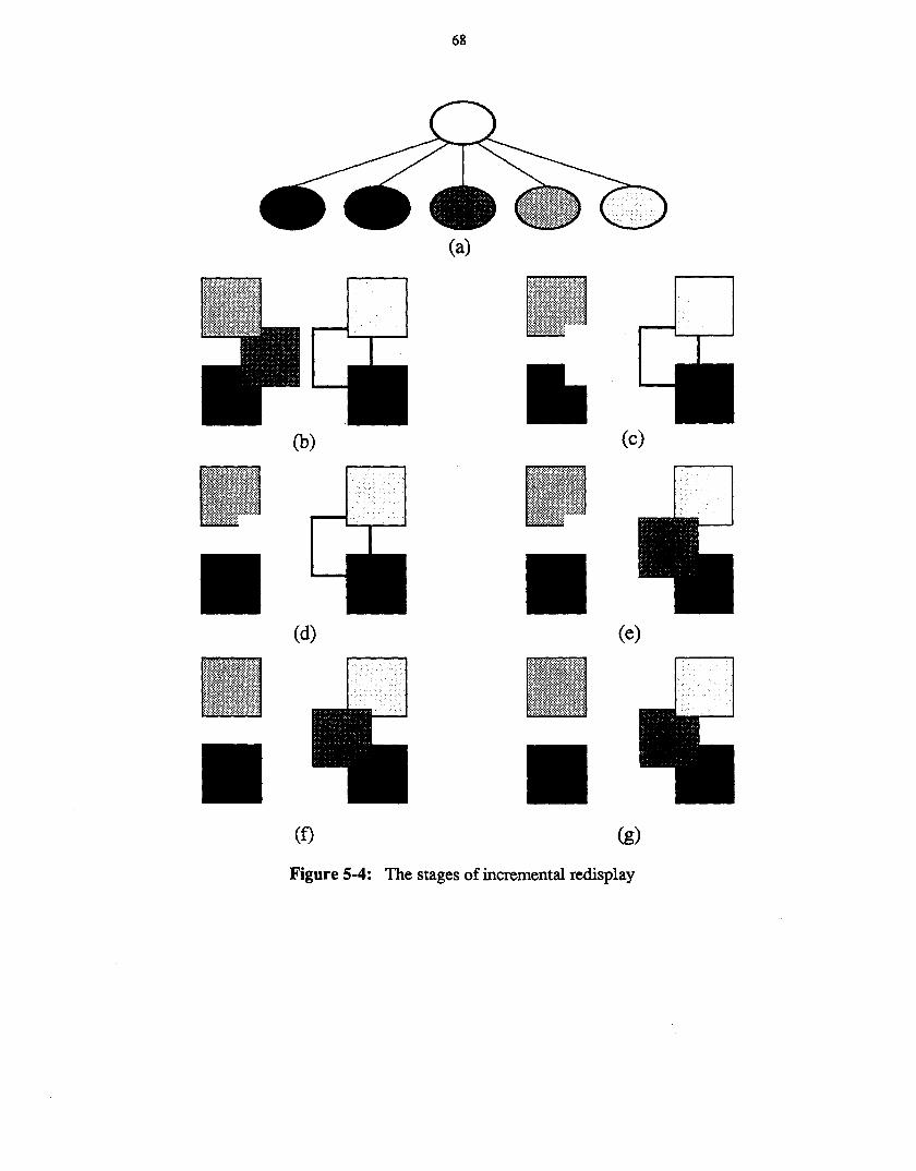
68
(a)
(b)
•• (c)
•
•
Cd)
(0
•
•
(e)
(g)
Figure 5-4: The stages of incremental redisplay
69
Another solution is to add a built-in function to the language that takes an object and returnsits current transformation. The editor would use
(concat (currtrans <object» <new transform»
in the transform statement. This has the problem that it makes an object's transformation anaccessible part of the program state. All the benefits obtained by making this state invisible arelost.
The best solution would be to keep a symbolic representation of the current transformation,and use that as the old transformation in the transform statement. This solution works well but isquite a bit of bookkeeping.
The solution actually used in Dee solves the problem by avoiding it: a new statementrtransform, or relative transform, was added to Dum. Rtransform is defined so that the twostatements
(rtransform <object> <new transform»(transform <object> (concat <object's transform> <new transform»)
have the same results. This solution, while not quite as elegant as the previous solution, wasconsiderably easier to implement. The editor actually produces rtransform statements ratherthan transform statements in response to the user moving objects.
The same problem arises when the user copies an object: Dee must translate the displacementfor the new object into an absolute position. This is solved in the same way, by adding an mewfunction that creates a new copy of an object relative to where the old one is.
Something subtly unusual goes on with transformations when transforming things in agraphics editor. This is best explained by first giving an example: Assume the user has created asquare at the point (50,50). The correct code to do this is
(with (translate [50 50])(object a_square (square»
)
If the user then rotates the square by 10°, the resulting code should have the same effect as(with (translate [50 50])
(with (rotate 10)(object a_square (square»
)
In other words, the rotation should be performed upon the square before the translation (Recallthat transformations are successively applied to the coordinate system from the outside in orsuccessively applied to the object from the inside out. Either view yields the same results). Itappears that subsequent transformations should be nested inside the extant ones. If, however, therotation is then followed by a translation of (20,0) the user expects the rotated square to movetwenty units to the right; that is, the result should have the effect of
(with (translate [70 50])(with (rotate 10)
(object a_square (square»
)
and not of
70
(with (translate [50 50])(with (rotate 10)
(with (translate [20 0])(object a_square (square»
)
In the second code example the innermost translation would be along a line rotated 10° from thehorizontal, not the same thing at all.
More generally, the object's current transformation C can be decomposed into a linear component CL and a translation component CT; C is the product C~L- A new transformation, N,can similarly be decomposed into NrNL- IfN is applied to the object after C the result should be,not NC as might be expected, but rather N~yNLCL' The graphics editor must be careful to putthe transformations together in the right order.
5.14. Source-code optimizationAfter being edited for a while with Dee, Dum programs tend to become littered with lots of
rtransform, raise, lower, delete and recall statements, obscuring program flow and increasingexecution time. A source code optimizer can improve the program considerably.11
This version of the optimization algorithm removes rtransform, delete, and recall statementsbut leaves raise and lower statements in the program. Removing these statements is slightlymore complex since it involves reordering the statements in the program but would proceedalong the same general scheme.
This is the optimization algorithm:
1. Traverse the execution tree of the program. For every object that is created, keepthe following information:
• A pointer into the parse tree to the invocation.
• Whether or not the invocation is in a loop. If so, the invocation cannot bemodified or deleted since doing so might change or delete the invocations ofother objects.
• Whether or not the invocation contains any calls to user-defined functions.If it does, it cannot be deleted since user-defined functions can have sideeffects in the picture.
• Pointers to each object used in the invocation. As long as the current objectexists, these objects cannot be removed.
• A pointer into the parse tree to the draw statement that drew the object, ifany.
• Whether or not the draw statement is in a loop and also uses a subscript calculation to find the object. If so, it cannot be removed since doing so mightdelete the other objects from the picture .
IlOue to time pressure, Dee's source code optimizer was never completely implemented.
7
71
• A list of actions for the object: recall, delete, and rtransform statements,uses of the object or its control points in other object invocations, and uses ofthe object or its control points in other places. Each of these contains apointer into the parse tree where the action occurs; the recall, delete, andrtransform statements also indicate whether or not the statement is safe tooptimize away. A statement is unsafe if it uses user-defined functions, if itoccurs in a loop and uses a subscript calculation to fmd the object, or if itoccurs in a variant of the object originally defining the current object.
Put all records containing this information into a list of unoptimized objects.
2. Repeat until the list of unoptimized objects is empty:a. Pick an unoptimized object.
b. Move it to a list of optimized objects.
c. Go down the list of activities and, depending upon the type, do differentthings:
• Recall: If the recall statement is unsafe to remove or the invocationis unsafe to modify, skip this activity. Otherwise, change the invocation into the result of the recall statement and remove the recall statement from the parse tree.
• Delete: If either the delete statement or the object's draw statementis unsafe to remove, skip this activity. Otherwise, remove the deletestatement and the draw statement from the parse tree. Be sure to fixthe pointer to the draw statement in the optimization record.
• Rtransform: If the rtransform statement is unsafe to remove, skipthis activity. If not, there are two possibilities. If the invocation issafe to modify, remove the rtransform statement and add a new withstatement around the invocation. Otherwise, if there is a previousrtransform statement that is safe to modify, remove the currentrtransform and concatenate its transformation into that of the previous rtransform. This can only be done if the current rtransform isnot contained in a variant of the object containing the previousrtransform.
• Object and control point uses: skip these activities.
d. After going through the activities, see if the invocation can be removed.This is possible if the activity list is now empty, the optimization recordindicates there is no draw statement, and the invocation is safe to modify.If these all hold, remove the invocation of this object and go through the listof objects used in the invocation and, for each one, delete the activityrecord referring to the use. Move the object from the optimized list back tothe unoptimized list if it has already been optimized, thereby allowing objects used only in other invocations to be removed if the other invocationsall go away.
3. Now go through the parse tree and collapse any nested with statements into a singleone. If consecutive transformations are of the same type, for example two translations, they can be combined into a single transformation; if not, they can be combined with the concat function. Also in this pass remove any statements that have
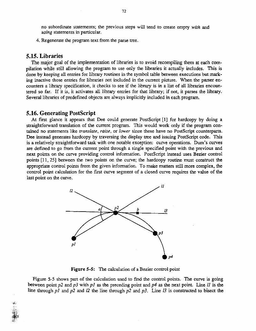
72
no subordinate statements; the previous steps will tend to create empty with andusing statements in particular.
4. Regenerate the program text from the parse tree.
5.15. LibrariesThe major goal of the implementation of libraries is to avoid recompiling them at each com
pilation while still allowing the program to use only the libraries it actually includes. This isdone by keeping all entries for library routines in the symbol table between executions but marking inactive those entries for libraries not included in the current picture. When the parser encounters a library specification, it checks to see if the library is in a list of all libraries encountered so far. If it is, it activates all library entries for that library; if not, it parses the library.Several libraries of predefined objects are always implicitly included in each program.
5.16. Generating PostScriptAt first glance it appears that Dee could generate PostScript [1] for hardcopy by doing a
straightforward translation of the current program. This would work only if the program contained no statements like translate, raise, or lower since these have no PostScript counterparts.Dee instead generates hardcopy by traversing the display tree and issuing PostScript code. Thisis a relatively straightforward task with one notable exception: curve operations. Dum's curvesare defined to go from the current point through a single specified point with the previous andnext points on the curve providing control information. PostScript instead uses Bezier controlpoints [11, 25] between the two points on the curve; the hardcopy routine must construct theappropriate control points from the given information. To make matters still more complex, thecontrol point calculation for the first curve segment of a closed curve requires the value of thelast point on the curve.
p4
Figure 5-5: The calculation of a Bezier control point
Figure 5-5 shows part of the calculation used to fmd the control points. The curve is goingbetween point p2 and p3 with pI as the preceding point and p4 as the next point. Line II is theline through pI and p2 and 12 the line through p2 and p3. Line /3 is constructed to bisect the
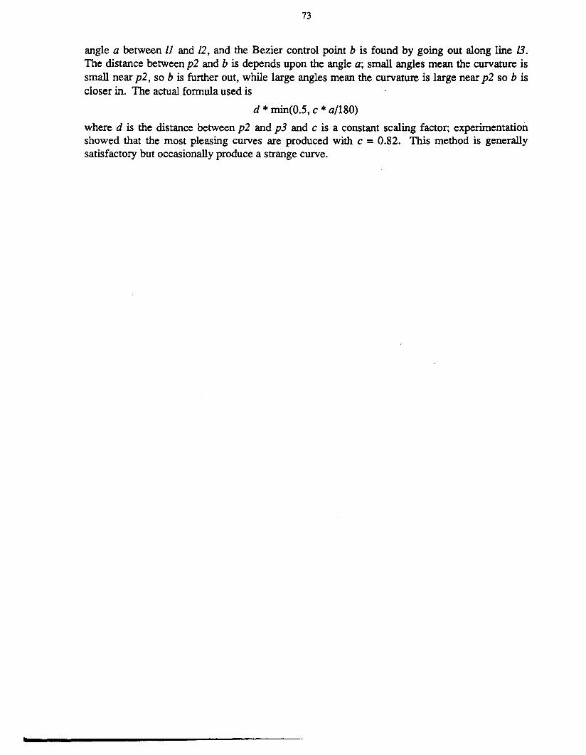
•
73
angle a between 11 and /2, and the Bezier control point b is found by going out along line 13.The distance between p2 and b is depends upon the angle a; small angles mean the curvature issmall near p2, so b is further out, while large angles mean the curvature is large near p2 so b iscloser in. The actual formula used is
d * min(O.5, c *a/180)
where d is the distance between p2 and p3 and c is a constant scaling factor; experimentationshowed that the most pleasing curves are produced with c = 0.82. This method is generallysatisfactory but occasionally produce a strange curve.
74
6. Contributions and Future Work
6.1. ContributionsTweedle fully integrates a procedural language and a graphics editor. Chapter 3 referred to
the "carefully cultivated illusion" that the language serves a subsidiary function to the editor;one measure of the success of the marriage between language and editor is how well this illusionsucceeds. How frequently does the user need to edit the program text directly? In my experience creating drawings for this thesis I have encountered four classes of situations requiringtext editing:
1. Creating objects which require procedurality: these are the cases for which textediting was intended. Because of the nature of the illustrations they tended tocome up more frequently than they might normally.
2. Providing exact values for point variables: this was also intended, but proved to befar commoner and far more tedious than originally expected. Gargoyle's snapdragging technique [9] would drastically reduce the need for these types of interactions.
3. Deleting code for editing actions performed incorrectly or by mistake: Dee has no"Undo" function, so these had to be manually removed from the program. An"Undo" function would eliminate these interactions.
4. Hand-optimizing code: since the source code optimizer was never fmished, anyoptimization had to be done manually. This only arose for examples where thecode was to be shown in the text. Finishing the optimizer would eliminate this.
The editing process in general runs quite smoothly. I frequently would switch back and forthbetween making text changes and graphics changes in the same session; having both styles ofinteraction available at the same time is a valuable tool. Even if the graphics editor were unavailable the incremental execution facilities make Dee a good environment for writing anddebugging graphics programs. The current implementation frequently sacrifices efficiency forsimplicity and yet its response time is quite good; this shows that there is nothing inherently slowabout the ideas embodied in Dee, and with some work Dee could be made to execute as quicklyas any other graphics editor.
Tweedle's greatest contribution is in extending the realm of procedural representations to interactive programs. All procedural representations done previously have been rather batchoriented: the representation is created and them moved as a whole to its consumer, a documentcompiler or a printer. Tweedle is interactive; changes to a program take place incrementally. Inorder to make this work well the interpreter must understand the structure and execution of aprogram so that it can execute appropriate parts of a program as the representation changes.Static structure in the language allows the interpreter to gain the information it needs by staticanalysis of the program text.
Tweedle's drawing model combines segment and procedure based models by treating drawingprocedures in an object-oriented fashion. Object defmitions are as simple as drawingprocedures, but having their result be manipulable by the program gives the advantages of segments. The variation hierarchy in Dum is analogous to the class hierarchy in object-orientedsystems.
75
The moral of the story is that procedural representation languages are still progranuning languages, and their design can benefit from the same techniques used to design general purposelanguages. Besides static structure and an object-oriented drawing model, Dum has subroutinelibraries and typed subroutine parameters. Libraries allow multiple pictures to share commonelements and allow people other than the picture creator to do the programming necessary forcomplicated objects. Typed parameters allow the editor to figure out what kinds of values tosupply as arguments to newly instantiated objects and how it should supply them.
The object variation hierarchy is a new idea in editing facilitated by Dum's procedurality.Describing the change from original to variant as the series of editing operations that effect thechange is natural, intuitive, and directly models the editing process. In Dum one can move asubobject around; in the procedural model having something be in different places at differentpoints in the execution is perfectly reasonable. A declarative model would require either somesort of meta-syntax to describe the change process or a means of resolving conflicting descriptions such as the original claiming the subobject is in location A but the variant claiming it's inlocation B. The main benefit of variation over simply copying the definition and changing it isthat the variant can follow later changes made to the original object. This benefit has shown upmost in allowing slightly different objects that should remain consistent with each other; thevarious labeled ellipses and rectangles used in illustrations in this theses are an example of this.
The incremental execution facilities have worked out extremely well and should be applicableto other systems with rapidly changing representations.
6.2. Deficiencies & future workDee is far from being a production-quality editor. Besides small things like line join styles,.
generalized fill patterns, and color, the two major missing features are source-code optimizationand grouping. Optimization was fully described in Section 5.14; grouping is the ability to perform actions in the graphics editor to more than one object at a time.
There are many places in Dee where it was easier to always recompute information than tokeep state that would allow Dee to determine if the current information was still valid. Boundingboxes and redisplay are the two most notable examples of this; whenever the structure of theimage changes at all Dee recomputes all the bounding boxes and redisplays the picture. Thedelay caused by this could easily be eliminated by the more clever algorithms described in Section 5.12.
The editor would benefit from a finer grade of incremental execution. The present schemeworks well for nicely structured diagrams with many short object defmitions; unfortunately, thischaracterizes only a subset of possible pictures. Many programs tum out to have a very flatstructure consisting of a long main program calling library objects. Any change other than adding new code at the end of the program requires complete reexecution. The interpreter couldimprove its response for programs like these by checkpointing the state at frequent intervalsthrough the main program.
When adding an object the editor always prompts for the parameters the same way; as far as itis concerned a line segment with one point parameter and a circle with one point parameter lookthe same. More sophisticated interaction techniques like rubber-banded lines, circles, or rec-

76
tangles could be provided by allowing an object definition to designate some kind of interactionfunction that the editor would call for each parameter. These interaction functions, written inDum and included in the same libraries as the objects they apply to, would provide the interactive feedback necessary to support the appropriate type of rubber banding for each type ofobject.
Object definitions act as mathematical functions since their action depends only upon thevalues of their variables. Object invocations are thus well suited to being executed in parallel;one invocation cannot affect the execution of another. The parallel execution of Dum programsis an interesting research area.
Dee's internal model has the editor creating new code and passing it to the interpreter, whichadds it to the program and executes it to update the display. This has the advantage that it isimmediately obvious if the editor is generating incorrect code. An interesting alternative structure would be for the editor to both modify the program and change the display directly. Withthis approach the incremental execution mechanism only needs to be invoked when the userchanges the program with the text editor. Changes to the text should occur rarely enough thatthe extra time needed to fully reexecute in response to such a change shouldn't be too much of abother, so incremental execution could be completely disposed of. Experimentation is needed tosee if the extra time spent by Dee providing for incremental execution is recovered by the timesaved by incrementally executing programs.
6.3. What I would do differentlyThe X Window System [12] proved to be simple and easy to use; it also proved to be critically
lacking in high-level capabilities. Particularly missed was the ability to define editable sectionsof text on the screen, a feature present in Andrew [23]. This lack led to a baroque process structure for Dee: an editing session consists of the main Dee process, two copies of the terminalemulator program, and a copy of Emacs, all communicating through interprocess communicationmechanisms. This turned out to work surprisingly well (1 was rather surprised to get it to work atall!) but would have all been completely unnecessary in a more full-featured window system.
Dee uses X's curve mechanism; this was easy to implement but has been a source of difficultyever since. X's curves go through specified points but frequently do very unintuitive thingsbetween these points. Duplicating these curves exactly in hard copy is neither easy nor in manycases particularly desirable. 1 originally believed simulating a more accurate curve mechanismlike B-splines using straight line segments would be intolerably slow but recent work by otherpeople has demonstrated otherwise.
An editing session in Dee consists of creating a complex interlinked data structure, the execution tree, and then repeatedly throwing pieces of it away and replacing them with new data. Thememory management problems turned out to be immense; 1 estimate that a month of implementation time was spent on tasks that would have completely gone away if garbage collection hadbeen available.
Paths need to become full-fledged datatypes. They were not so designed at first sincePostScript seemed to get along quite well without them, but they have ended up in something ofa state of limbo. The editor never creates paths and it cannot do anything useful with them if the

<I
.-
I I
user does. Paths end up getting hidden away in object defmitions where the editor never needsto look at them. An even more serious deficiency is that variant objects cannot modify paths inthe original object since it has no way to refer to them. The lack of a path datatype also makes itimpossible to extend the various routines used to create different line styles in Figure 1-2 to work:on arbitrary paths.
78
Acknowledgments"You ought to return thanks in a neat speech," the Red
Queen said, frowning at Alice as she spoke.- Lewis Carroll
First, my sincerest thanks go to my advisor, Brian Reid, whose assistance and good naturehave been a constant source of inspiration throughout the years. Without Brian's confidence inme this thesis would most likely never have been written.
Thanks also to the other members of my reading committee, Forest Baskett and especiallyMark Linton. Mark's constant questioning of my assumptions helped me to crystallize myreasoning and improve my explanations; he also provided the hardware I used for my implementation.
Of the many people I have known at Stanford, two deserve special recognition: Barry Hayes,who frequently provided a willing and critical ear when I wanted to discuss possible alternativesduring the design and implementation of Tweedle; and Glenn Trewitt, who was always willing tobe dragged out to see my latest demonstration and who always seemed to be able to provideanything I needed, be it office supplies, documentation, tools, or chocolate. I would also like tothank Lia Adams, Ginger Edighoffer, Jay Gischer, Tom Lehmann, Harold Ossher, MarvinTheimer, and Frank Yellin for many enjoyable times, and the Diners Club for regularlyscheduled comic relief.
My years at Stanford would have been far less enjoyable were it not for my association withthe Stanford Savoyards. Special thanks go to my friends Ronnie Cooperstein, Richard Dodge,David Gauntt, Bonnie Senko, and Mike Thornburg.
Finally, there is one person whose love and companionship have kept me going through thepast several years, who made my successes more fulfilling and my discouragements morebearable by sharing them. I would like to dedicate this thesis, with love, to Ron Jenks.

80
I. Syntax of the Dum LanguageIn this description, SMALL CAPITALS denote nontenninals, boldface denotes terminals, and
italics indicate explanatory information.
Conventional syntax is used: ' '*" indicates zero or more of the preceding item, square brackets enclose optional material, and "I" separates alternatives. Quotation marks and parenthesesare always terminals; square brackets, asterisks and vertical bars are always meta-syntax exceptin the productions for LBRACKET, RBRACKET, STAR, and VBAR.
PROGRAM ~ LffiRARY-SPEC* ROUTINE*
LIBRARY-SPEC ~ $library TEXT-STRING NEWLINE
ROUTINE ~ FUNCTION-DEFINITION I OBJECT-DEFINITION
FUNCTION-DEFINITION ~ ( function NAME [ RETURNS-CLAUSE] [ ARGS·CLAUSE ]METHOD-CLAUSE)
OBJECT-DEFINITION ~ (defineobject NAME [VARIANT-CLAUSE] [ARGS-CLAUSE][ CONTROL-CLAUSE] METHOD-CLAUSE)
RETURNS-CLAUSE ~ (returns DATATYPE)
VARIANT-CLAUSE ~ ( variant NAME )
ARGS-CLAUSE ~ ( args ARG-SPEC* )
ARG-SPEC ~ (DATATYPE NAME*)
CON1ROL-CLAUSE ~ ( control NAME* )
METHOD-CLAUSE ~ ( method STATEMENT-LIST)
STATEMENT-LIST ~ STATEMENT*
STATEMENT ~ NORMAL-STATEMENT I ROUTINE-CALL
NORMAL-STATEMENT ~ DATA-DEFINITION I WITH-STATEMENT I PATH-STATEMENT IIF-STATEMENT I FOR-STATEMENT IWHILE-STATEMENT IBEGIN-STATEMENT I ASSIGNMENT ITRANSFORM-STATEMENT I RTRANSFORM-STATEMENT IRECALL-STATEMENT I DELETE-STATEMENT IDRAW-STATEMENT I RAISE-STATEMENT ILOWER-STATEMENT I USING-STATEMENT IPATH-CONSTRUCTOR
DATA-DEFINITION ~ ( DATATYPE NAME [ initial-EXPRESSION] )
WITH-STATEMENT ~ ( with transformation-EXPRESSION STATEMENT-LIST)
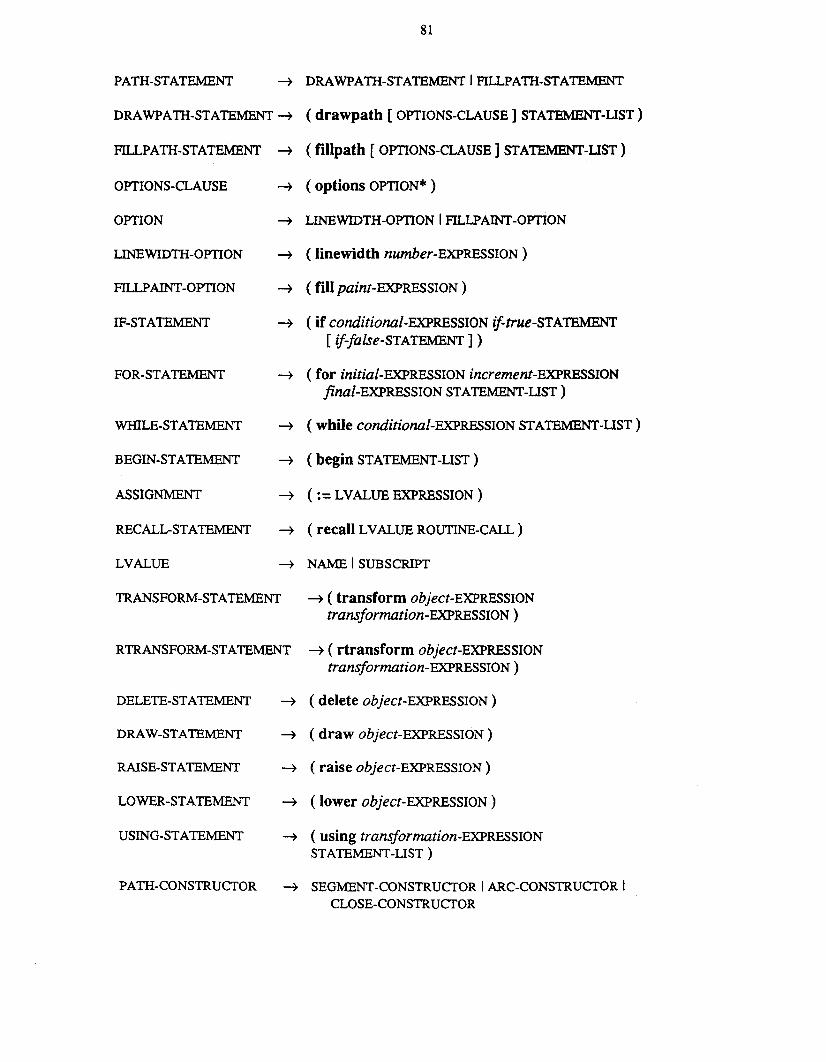
PATH-STATEMENT
81
~ DRAWPATH-STAlEMENT I FILLPATH-STAlEMENT
DRAWPATH-STAlEMENT ~ (drawpath [OPTIONS-CLAUSE] STATEMENT-UST)
FILLPATH-STATEMENT ~ (fillpath [ OPTIONS-CLAUSE] STATEMENT-LIST)
OPTIONS-CLAUSE ~ (options OPTION* )
OPTION ~ LINEWIDTH-OPTION I FILLPAINT-OPTION
UNEWIDTH-OPTION ~ (linewidth number-EXPRESSION)
FILLPAINT-OPTION ~ (fillpaint-EXPRESSION)
IF-STAlEMENT ~ (if conditional-EXPRESSION if=-true-STAlEMENT[ if-false-STATEMENT] )
FOR-STAlE:MENT ~ (for initial-EXPRESSION increment-EXPRESSIONjinal-EXPRESSION STAlEMENT-LIST )
WHILE-STAlEMENT ~ (while conditional-EXPRESSION STAlEMENT-UST)
BEGIN-STAlEMENT ~ (begin STAlEMENT-LIST)
ASSIGNMENT ~ (:= LVALUE EXPRESSION)
RECALL-STAlEMENT ~ (recall LVALUE ROUTINE-CALL)
LVALUE ~ NAME I SUBSCRIPT
TRANSFORM-STATEMENT ~ ( transform object-EXPRESSIONtransformation-EXPRESSION)
RTRANSFORM-STAlEMENT ~ ( rtransform object-EXPRESSIONtransformation-EXPRESSION)
DELETE-STAlEMENT ~ ( delete object-EXPRESSION)
DRAW-STAlEMENT ~ ( draw object-EXPRESSION)
RAISE-STAlEMENT ~ ( raise object-EXPRESSION)
LOWER-STAlEMENT ~ (lower object-EXPRESSION)
USING-STAlEMENT ~ (using transformation-EXPRESSIONSTAlEMENT-LIST)
PATH-CONSTRUCTOR ~ SEGMENT-CONSTRUCTOR I ARC-CONSTRUCTOR ICLOSE-CONSTRUCTOR
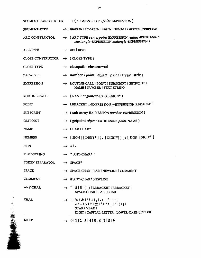

83
CAPITAL-LEITER -+ A IB IC IDIE IFIG I H II IJ IK ILIM INIOIPIQIRISITIUIVIWIXIYIZ
LOWER-CASE-LETTER -+ a I b I c I die I fig I h I i I j I kill m Inlolplqlrlsltlulvlwlxlylz
LBRACKET -+ [
RBRACKET -+ ]
STAR -+ *
VBAR -+
Notes:1. A TOKEN·SEPARATOR may appear between any two consecutive tokens. Any two
adjacent NAMES must be separated by a TOKEN-SEPARATOR.
2. At least one of the DIGIT strings in a NUMBER must be present.
3. NUMBERS are a subset of NAMES; any NAME that qualifies as a NUMBER is aNUMBER, not a NAME.
4. Quotation marks are included in STRINGS by doubling them.
5. SPACE·CHAR, TAB, and NEWLINE are ASCn characters octal 40, 11, and 12,respectively.
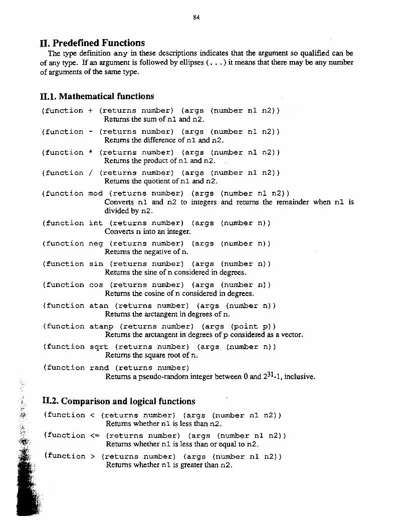
84
Il, Predefined FunctionsThe type defmition any in these descriptions indicates that the argument so qualified can be
of any type. If an argument is followed by ellipses ( .•. ) it means that there may be any numberof arguments of the same type.
11.1. Mathematical functions
(function + (returns number) (args (number nl n2»Returns the sum of nl and n2.
(function - (returns number) (args (number nl n2»Returns the difference of nl and n2.
(function * (returns number) (args (number nl n2»Returns the product of nl and n2.
(function / (returns number) (args (number nl n2»Returns the quotient of nl and n2.
(function mod (returns number) (args (number nl n2»Converts nl and n2 to integers and returns the remainder when nl isdivided by n2.
(function int (returns number) (args (number n»Converts n into an integer.
(function neg (returns number) (args (number n»Returns the negative of n.
(function sin (returns number) (args (number n»Returns the sine of n considered in degrees.
(function cos (returns number) (args (number n»Returns the cosine of n considered in degrees.
(function atan (returns number) (args (number n»Returns the arctangent in degrees of n.
(function atanp (returns number) (args (point p»Returns the arctangent in degrees of p considered as a vector.
(function sqrt (returns number) (args (number n»Returns the square root of n.
(function rand (returns number)Returns a pseudo-random integer between 0 and 231_1, inclusive.
1I.2. Comparison and logical functions
(function < (returns number) (args (number nl n2»Returns whether nl is less than n2.
(function <= (returns number) (args (number nl n2»Returns whether nl is less than or equal to n2.
(function> (returns number) (args (number nl n2»Returns whether n 1 is greater than n2.
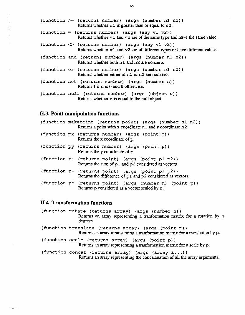
(function >= (returns number) (args (number nI n2»Returns whether n 1 is greater than or equal to n2.
(function = (returns number) (args (any vI v2»Returns whether v I and v2 are of the same type and have the same value.
(function <> (returns number) (args (any vI v2»Returns whether vI and v2 are of different types or have different values.
(function and (returns number) (args (number nI n2»Returns whether both n l, and n2 are nonzero.
(function or (returns number) (args (number nI n2»Returns whether either of nI or n2 are nonzero.
(function not (returns number) (args (number n»Returns 1 if n is 0 and 0 otherwise.
(function null (returns number) (args (object 0»Returns whether 0 is equal to the null object.
II.3. Point manipulation functions
(function makepoint (returns point) (args (number nl n2»Returns a point with x coordinate n l, and y coordinate n2.
(function px (returns number) (args (point p»Returns the x coordinate of p.
(function py (returns number) (args (point p»Returns the y coordinate of p.
(function p+ (returns point) (args (point pI p2»Returns the sum of p L and p2 considered as vectors.
(function p- (returns point) (args (point pI p2»Returns the difference of p l, and p2 considered as vectors.
(function p* (returns point) (args (number n) (point p»Returns p considered as a vector scaled by n.
11.4. Transformation functions
(function rotate (returns array) (args (number n»Returns an array representing atranformation matrix for a rotation by ndegrees.
(function translate (returns array) (args (point p»Returns an array representing a tranfonnation matrix for a translation by p.
(function scale (returns array) (args (point p»Returns an array representing a tranfonnation matrix for a scale by p.
(function concat (returns array) (args (array a ... »Returns an array representing the concatenation of all the array arguments.
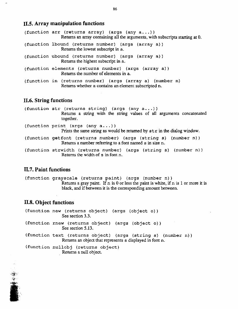
86
I1.5. Array manipulation functions
(function arr (returns array) (args (any a ... »Returns an array containing all the arguments, with subscripts starting at O.
(function lbound (returns number) (args (array a»Returns the lowest subscript in a.
(function ubound (returns number) (args (array a»Returns the highest subscript in a.
(function elements (returns number) (args (array a»Returns the number of elements in a.
(function in (returns number) (args (array a) (number n)Returns whether a contains an element subscripted n.
I1.6. String functions
(function str (returns string) (args (any a ... »Returns a string with the string values of all arguments concatenatedtogether.
(function print (args (any a ... »Prints the same string as would be returned by str in the dialog window.
(function getfont (returns number) (args (string s) (number n»Returns a number referring to a font named s in size n.
(function strwidth (returns number) (args (string s) (number n»Returns the width of s in font n.
IT.7. Paint functions
(function grayscale (returns paint) (args (number n»Returns a gray paint. If n is 0 or less the paint is white, if n is 1 or more it isblack, and if between it is the corresponding amount between.
IT.S. Object functions
(function new (returns object) (args (object 0»See section 3.3.
(function rnew (returns object) (args (object 0»See section 5.13.
(function text (returns object) (args (string s) (number n»Returns an object that represents s displayed in font n.
(function nullobj (returns object)Returns a null object.
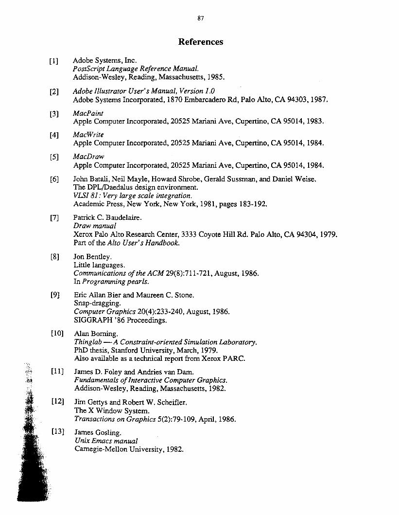
87
References
[1] Adobe Systems, Inc.Postscript Language Reference Manual.Addison-Wesley, Reading, Massachusetts, 1985.
[2] Adobe Illustrator User's Manual, Version 1.0Adobe Systems Incorporated, 1870 Embarcadero Rd, Palo Alto, CA 94303,1987.
[3] MacPaintApple Computer Incorporated, 20525 Mariani Ave, Cupertino, CA 95014,1983.
[4] MacWriteApple Computer Incorporated, 20525 Mariani Ave, Cupertino, CA 95014, 1984.
[5] MacDrawApple Computer Incorporated, 20525 Mariani Ave, Cupertino, CA 95014,1984.
[6] John Batali, Neil Mayle, Howard Shrobe, Gerald Sussman, and Daniel Weise.The DPL/Daedalus design environment.VLSI 81: Very large scale integration.Academic Press, New York, New York, 1981, pages 183-192.
[7] Patrick C. Baudelaire.Draw manualXerox Palo Alto Research Center, 3333 Coyote Hill Rd. Palo Alto, CA 94304, 1979.Part of the Alto User's Handbook.
[8] Jon Bentley.Little languages.Communications ofthe ACM 29(8):711-721, August, 1986.In Programming pearls.
[9] Eric Allan Bier and Maureen C. Stone.Snap-dragging.Computer Graphics 20(4):233-240, August, 1986.SIGGRAPH '86 Proceedings.
[10] Alan Borning.Thinglab -A Constraint-oriented Simulation Laboratory.PhD thesis, Stanford University, March, 1979.Also available as a technical report from Xerox PARC.
[11] James D. Foley and Andries van Dam.Fundamentals ofInteractive Computer Graphics.Addison-Wesley, Reading, Massachusetts, 1982.
[12] Jim Gettys and Robert W. Scheifler.The X Window System.Transactions on Graphics 5(2):79-109, April, 1986.
[13] James Gosling.Unix Emacs manualCarnegie-Mellon University, 1982.
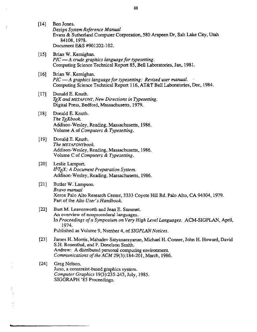
t
88
[14] Ben Jones.Design System Reference ManualEvans & Sutherland Computer Corporation, 580 Arapeen Dr, Salt Lake City, Utah
84108, 1978.Document E&S #901202-102.
[15] Brian W. Kernighan.PIC-A crude graphics language for typesetting.Computing Science Technical Report 85, Bell Laboratories, Jan, 1981.
[16] Brian W. Kernighan.PIC - A graphics language for typesetting: Revised user manual. .Computing Science Technical Report 116, AT&T Bell Laboratories, Dec, 1984.
[17] Donald E. Knuth.TEX and METAFONI', New Directions in Typesetting.Digital Press, Bedford, Massachusetts, 1979.
[18] Donald E. Knuth.The TEXbook.Addison-Wesley, Reading, Massachusetts, 1986.Volume A of Computers & Typesetting.
[19] Donald E. Knuth.The METAFONI'book.Addison-Wesley, Reading, Massachusetts, 1986.Volume C of Computers & Typesetting.
[20] Leslie Lamport.LATEX: A Document Preparation System.Addison-Wesley, Reading, Massachusetts, 1986.
[21] Butler W. Lampson.Bravo manualXerox Palo Alto Research Center, 3333 Coyote Hill Rd. Palo Alto, CA 94304,1979.Part of the Alto User's Handbook.
[22] Burt M. Leavenworth and Jean E. Sammet.An overview of nonprocedural languages.In Proceedings ofa Symposium on Very High Level Languages. ACM-SIGPLAN, April,
1974.Published as Volume 9, Number 4, of SIGPLAN Notices.
[23] James H. Morris, Mahadev Satyanarayanan, Michael H. Conner, John H. Howard, DavidS.H. Rosenthal, and F. Donelson Smith.Andrew: A distributed personal computing environment.Communications of the ACM 29(3):184-201, March, 1986.
[24] Greg Nelson.Juno, a constraint-based graphics system.Computer Graphics 19(3):235-243, July, 1985.SIGGRAPH '85 Proceedings.
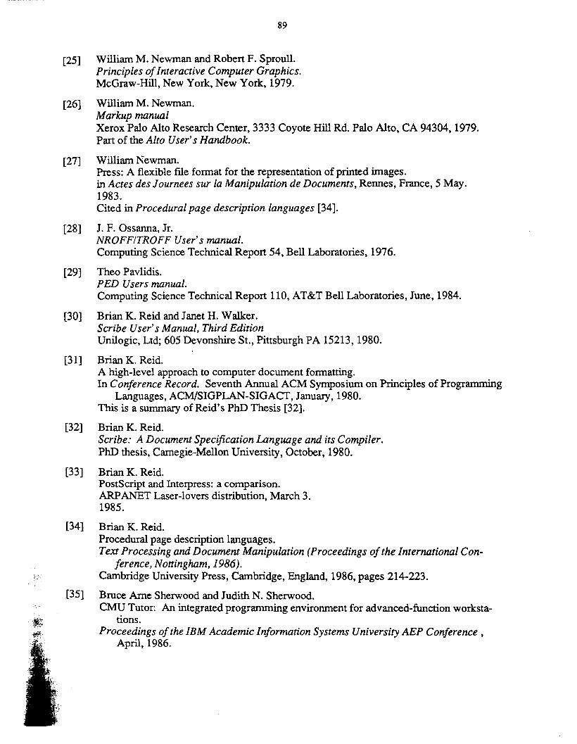
89
[25] William M. Newman and Robert F. Sproull.Principles ofInteractive Computer Graphics.McGraw-Hill, New York, New York, 1979.
[26] William M. Newman.Markup manualXerox Palo Alto Research Center, 3333 Coyote Hill Rd. Palo Alto, CA 94304,1979.Part of the Alto User's Handbook.
[27] William Newman.Press: A flexible file format for the representation of printed images.in Actes des Journees sur la Manipulation de Documents, Rennes, France, 5 May.1983.Cited in Procedural page description languages [34].
[28] J. F. Ossanna, JI.NROFFITROFF User's manual.Computing Science Technical Report 54, Bell Laboratories, 1976.
[29] Theo Pavlidis.PED Users manual.Computing Science Technical Report 110, AT&T Bell Laboratories, June, 1984.
[30] Brian K. Reid and Janet H. Walker.Scribe User's Manual, Third EditionUnilogic, Ltd; 605 Devonshire St., Pittsburgh PA 15213, 1980.
[31] Brian K. Reid.A high-level approach to computer document formatting.In Conference Record. Seventh Annual ACM Symposium on Principles of Programming
Languages, ACM/SIGPLAN-SIGACT, January, 1980.This is a summary of Reid's PhD Thesis [32].
[32] Brian K. Reid.Scribe: A Document Specification Language and its Compiler.PhD thesis, Carnegie-Mellon University, October, 1980.
[33] Brian K. Reid.PostScript and Interpress: a comparison.ARPANET Laser-lovers distribution, March 3.1985.
[34] Brian K. Reid.Procedural page description languages.Text Processing and Document Manipulation (Proceedings ofthe International Con
ference, Nottingham, 1986).Cambridge University Press, Carnbridge, England, 1986, pages 214-223.
[35] Bruce Arne Sherwood and Judith N. Sherwood.CMU Tutor: An integrated programming environment for advanced-function worksta
tions.Proceedings of the IBM Academic Information Systems University AEP Conference,
April, 1986.
fI~.
90
[36] Bruce Arne Sherwood and Judith N. Sherwood.The CMU Tutor Language (Preliminary Edition).Stipes Publishing, Champaign, Illinois, 1986.
[37] ACM SIGGRAPH.Status report of the graphic standards planning committee of ACM/SIGGRAPH.Computer Graphics 11(3), Fall, 1977.
[38] ACM SIGGRAPH.Information Processing Systems Computer Graphics Graphical Kemal System.Computer Graphics 18(Special issue), Feb, 1984.
[39] Richard M. Stallman.EMACS: The Extensible, Customizable, Self-Documenting Display Editor.AI Memo 519a, MIT, March, 1981.
[40] Ivan Edward Sutherland.Sketchpad, A Man-machine Graphics Communication System.Garland Publishing, New York, New York, 1980.Ph.D. Thesis, MIT, 1963.
[41] Xerox Corporation.JaM ManualXerox Palo Alto Research Center, 1980.Never published.
[42] Interpress Electronic Printing StandardXerox Corporation, Stamford, Connecticut 06904, 1984.Document number XSIS 04804, cited in Procedural page description languages [34].