edition 1.0 2013-08 international standard …ed1.0}b.pdf · edition 1.0 2013-08 international...
TRANSCRIPT

IEC 62680-3 Edition 1.0 2013-08
INTERNATIONAL STANDARD NORME INTERNATIONALE
Universal serial bus interfaces for data and power – Part 3: USB Battery Charging Specification, Revision 1.2 Interfaces de bus universel en série pour les données et l'alimentation électrique – Partie 3: Spécification de chargement des batteries USB, révision 1.2
INTERNATIONAL ELECTROTECHNICAL COMMISSION
COMMISSION ELECTROTECHNIQUE INTERNATIONALE XB ICS 29.220; 35.200
PRICE CODE CODE PRIX
ISBN 978-2-8322-1049-9
® Registered trademark of the International Electrotechnical Commission Marque déposée de la Commission Electrotechnique Internationale
®
Warning! Make sure that you obtained this publication from an authorized distributor. Attention! Veuillez vous assurer que vous avez obtenu cette publication via un distributeur agréé.
colourinside
This is a preview - click here to buy the full publication

– 2 – 62680-3 © IEC:2013 © USB-IF:2012
INTERNATIONAL ELECTROTECHNICAL COMMISSION
____________
UNIVERSAL SERIAL BUS INTERFACES FOR DATA AND POWER –
Part 3: USB Battery Charging Specification, Revision 1.2
FOREWORD
1) The International Electrotechnical Commission (IEC) is a worldwide organization for standardization comprising all national electrotechnical committees (IEC National Committees). The object of IEC is to promote international co-operation on all questions concerning standardization in the electrical and electronic fields. To this end and in addition to other activities, IEC publishes International Standards, Technical Specifications, Technical Reports, Publicly Available Specifications (PAS) and Guides (hereafter referred to as “IEC Publication(s)”). Their preparation is entrusted to technical committees; any IEC National Committee interested in the subject dealt with may participate in this preparatory work. International, governmental and non-governmental organizations liaising with the IEC also participate in this preparation. IEC collaborates closely with the International Organization for Standardization (ISO) in accordance with conditions determined by agreement between the two organizations.
2) The formal decisions or agreements of IEC on technical matters express, as nearly as possible, an international consensus of opinion on the relevant subjects since each technical committee has representation from all interested IEC National Committees.
3) IEC Publications have the form of recommendations for international use and are accepted by IEC National Committees in that sense. While all reasonable efforts are made to ensure that the technical content of IEC Publications is accurate, IEC cannot be held responsible for the way in which they are used or for any misinterpretation by any end user.
4) In order to promote international uniformity, IEC National Committees undertake to apply IEC Publications transparently to the maximum extent possible in their national and regional publications. Any divergence between any IEC Publication and the corresponding national or regional publication shall be clearly indicated in the latter.
5) IEC itself does not provide any attestation of conformity. Independent certification bodies provide conformity assessment services and, in some areas, access to IEC marks of conformity. IEC is not responsible for any services carried out by independent certification bodies.
6) All users should ensure that they have the latest edition of this publication.
7) No liability shall attach to IEC or its directors, employees, servants or agents including individual experts and members of its technical committees and IEC National Committees for any personal injury, property damage or other damage of any nature whatsoever, whether direct or indirect, or for costs (including legal fees) and expenses arising out of the publication, use of, or reliance upon, this IEC Publication or any other IEC Publications.
8) Attention is drawn to the Normative references cited in this publication. Use of the referenced publications is indispensable for the correct application of this publication.
9) Attention is drawn to the possibility that some of the elements of this IEC Publication may be the subject of patent rights. IEC shall not be held responsible for identifying any or all such patent rights.
International Standard IEC 62680-3 has been prepared by technical area 14: Interfaces and methods of measurement for personal computing equipment, of IEC technical committee 100: Audio, video and multimedia systems and equipment.
The text of this standard is based on documents prepared by the USB Implementers Forum (USB-IF). The structure and editorial rules used in this publication reflect the practice of the organization which submitted it.
The text of this standard is based on the following documents:
FDIS Report on voting
100/2157/FDIS 100/2190/RVD
Full information on the voting for the approval of this standard can be found in the report on voting indicated in the above table.
This is a preview - click here to buy the full publication

62680-3 © IEC:2013 – 3 – © USB-IF:2012
A list of all the parts in the IEC 62680 series, published under the general title Universal serial bus interfaces for data and power can be found on the IEC website.
The committee has decided that the contents of this publication will remain unchanged until the stability date indicated on the IEC web site under "http://webstore.iec.ch" in the data related to the specific publication. At this date, the publication will be
• reconfirmed, • withdrawn, • replaced by a revised edition, or • amended.
IMPORTANT – The 'colour inside' logo on the cover page of this publication indicates that it contains colours which are considered to be useful for the correct understanding of its contents. Users should therefore print this document using a colour printer.
This is a preview - click here to buy the full publication

– 4 – 62680-3 © IEC:2013 © USB-IF:2012
INTRODUCTION
The IEC 62680 series is based on a series of specifications that were originally developed by the USB Implementers Forum (USB-IF). These specifications were submitted to the IEC under the auspices of a special agreement between the IEC and the USB-IF.
The USB Implementers Forum, Inc. (USB-IF) is a non-profit corporation founded by the group of companies that developed the Universal Serial Bus specification. The USB-IF was formed to provide a support organization and forum for the advancement and adoption of Universal Serial Bus technology. The Forum facilitates the development of high-quality compatible USB peripherals (devices), and promotes the benefits of USB and the quality of products that have passed compliance testing.
ANY USB SPECIFICATIONS ARE PROVIDED TO YOU "AS IS, "WITH NO WARRANTIES WHATSOEVER, INCLUDING ANY WARRANTY OF MERCHANTABILITY, NON-INFRINGEMENT, OR FITNESS FOR ANY PARTICULAR PURPOSE. THE USB IMPLEMENTERS FORUM AND THE AUTHORS OF ANY USB SPECIFICATIONS DISCLAIM ALL LIABILITY, INCLUDING LIABILITY FOR INFRINGEMENT OF ANY PROPRIETARY RIGHTS, RELATING TO USE OR IMPLEMENTATION OR INFORMATION IN THIS SPECIFICAITON.
THE PROVISION OF ANY USB SPECIFICATIONS TO YOU DOES NOT PROVIDE YOU WITH ANY LICENSE, EXPRESS OR IMPLIED, BY ESTOPPEL OR OTHERWISE, TO ANY INTELLECTUAL PROPERTY RIGHTS.
Entering into USB Adopters Agreements may, however, allow a signing company to participate in a reciprocal, royalty-free licensing arrangement for compliant products. For more information, please see: http://www.usb.org/developers/docs/ http://www.usb.org/developers/devclass_docs#approved
IEC DOES NOT TAKE ANY POSITION AS TO WHETHER IT IS ADVISABLE FOR YOU TO ENTER INTO ANY USB ADOPTERS AGREEMENTS OR TO PARTICIPATE IN THE USB IMPLEMENTERS FORUM.”
This series covers the Universal Series Bus interfaces for data and power and consists of the following parts:
IEC 62680-1, Universal Serial Bus interfaces for data and power - Part 1: Universal Serial Bus Specification, Revision 2.0 IEC 62680-2, Universal Serial Bus interfaces for data and power - Part 2: USB Micro-USB Cables and Connectors Specification, Revision 1.01 IEC 62680-3, Universal Serial Bus interfaces for data and power - Part 3: USB Battery Charging Specification, Revision 1.2 IEC 62680-4, Universal Serial Bus interfaces for data and power - Part 4: Universal Serial Bus Cables and Connectors Class Document Revision. 2.0
This part of the IEC 62680 series consists of several distinct parts:
• the main body of the text, which consists of the original specification and all ECN and Errata developed by the USB-IF;
This is a preview - click here to buy the full publication
62680-3 © IEC:2013 – 5 – © USB-IF:2012
CONTENTS
1 Introduction ..................................................................................................................... 12 1.1 Scope .................................................................................................................... 12 1.2 Background ........................................................................................................... 12 1.3 Reference Documents ........................................................................................... 12 1.4 Definitions of Terms ............................................................................................... 12
1.4.1 Accessory Charger Adaptor ....................................................................... 12 1.4.2 ACA-Dock .................................................................................................. 13 1.4.3 Attach versus Connect ............................................................................... 13 1.4.4 Charging Downstream Port ........................................................................ 13 1.4.5 Charging Port ............................................................................................ 13 1.4.6 Dead Battery Threshold ............................................................................. 13 1.4.7 Dedicated Charging Port ............................................................................ 13 1.4.8 Downstream Port ....................................................................................... 14 1.4.9 Micro ACA ................................................................................................. 14 1.4.10 Portable Device ......................................................................................... 14 1.4.11 Rated Current ............................................................................................ 14 1.4.12 Standard ACA ........................................................................................... 14 1.4.13 Standard Downstream Port ........................................................................ 14 1.4.14 USB Charger ............................................................................................. 14 1.4.15 Weak Battery Threshold ............................................................................ 14
1.5 Parameter Values .................................................................................................. 14 1.6 OTG Considerations .............................................................................................. 15 1.7 Super Speed Considerations ................................................................................. 15
2 Dead Battery Provision ................................................................................................... 15 2.1 Background ........................................................................................................... 15 2.2 DBP – Unconfigured Clause .................................................................................. 15 2.3 DBP – Configured Clause ...................................................................................... 16
3 Charging Port Detection .................................................................................................. 17 3.1 Overview ............................................................................................................... 17 3.2 Charger Detection Hardware .................................................................................. 18
3.2.1 Overview ................................................................................................... 18 3.2.2 VBUS Detect ............................................................................................. 18 3.2.3 Data Contact Detect .................................................................................. 19 3.2.4 Primary Detection ...................................................................................... 22 3.2.5 Secondary Detection.................................................................................. 29 3.2.6 ACA Detection ........................................................................................... 32
3.3 Charger Detection Algorithms ................................................................................ 34 3.3.1 Weak Battery Algorithm ............................................................................. 34 3.3.2 Good Battery Algorithm .............................................................................. 35
3.4 Charger Detection Timing ...................................................................................... 36 3.4.1 Data Contact Detect Timing ....................................................................... 36 3.4.2 Detection Timing, CDP .............................................................................. 39
3.5 Ground Current and Noise Margins ........................................................................ 40 4 Charging Port and Portable Device Requirements ........................................................... 40
4.1 Charging Port Requirements .................................................................................. 40 4.1.1 Overshoot .................................................................................................. 40 4.1.2 Maximum Current ...................................................................................... 40
This is a preview - click here to buy the full publication
– 6 – 62680-3 © IEC:2013 © USB-IF:2012
4.1.3 Detection Renegotiation ............................................................................. 41 4.1.4 Shutdown Operation .................................................................................. 41 4.1.5 Failure Voltage .......................................................................................... 41 4.1.6 Multiple Ports............................................................................................. 41
4.2 Charging Downstream Port .................................................................................... 41 4.2.1 Required Operating Range ........................................................................ 41 4.2.2 Shutdown Operation .................................................................................. 42 4.2.3 Undershoot ................................................................................................ 42 4.2.4 Detection Signaling .................................................................................... 42 4.2.5 Connector .................................................................................................. 43
4.3 ACA-Dock .............................................................................................................. 43 4.3.1 Required Operating Range ........................................................................ 43 4.3.2 Undershoot ................................................................................................ 43 4.3.3 Detection Signaling .................................................................................... 43 4.3.4 Connector .................................................................................................. 43
4.4 Dedicated Charging Port ........................................................................................ 43 4.4.1 Required Operating Range ........................................................................ 43 4.4.2 Undershoot ................................................................................................ 44 4.4.3 Detection Signaling .................................................................................... 44 4.4.4 Connector .................................................................................................. 44
4.5 Accessory Charger Adapter ................................................................................... 45 4.5.1 Required Operating Range ........................................................................ 45 4.5.2 Undershoot ................................................................................................ 45 4.5.3 Detection Signaling .................................................................................... 45 4.5.4 Connector .................................................................................................. 45
4.6 Portable Device ..................................................................................................... 45 4.6.1 Allowed Operating Range .......................................................................... 45 4.6.2 Detection Signaling .................................................................................... 46 4.6.3 Detection Renegotiation ............................................................................. 46 4.6.4 Connector .................................................................................................. 47
5 Parameter Values ........................................................................................................... 47 6 Accessory Charger Adapter ............................................................................................ 50
6.1 Introduction ........................................................................................................... 50 6.2 Micro ACA ............................................................................................................. 52
6.2.1 Micro ACA Ports ........................................................................................ 52 6.2.2 Micro ACA Connectivity Options ................................................................ 53 6.2.3 Micro ACA Architecture .............................................................................. 54 6.2.4 Micro ACA Modes of Operation .................................................................. 54 6.2.5 Implications of not Supporting Micro ACA Detection .................................. 55 6.2.6 Micro ACA Requirements ........................................................................... 56 6.2.7 Portable Device State Diagram .................................................................. 57
6.3 Standard ACA ........................................................................................................ 59 6.3.1 Standard ACA Ports ................................................................................... 59 6.3.2 Standard ACA Architecture ........................................................................ 60 6.3.3 Standard ACA Modes of Operation ............................................................ 61 6.3.4 Implications of not Supporting Standard ACA Detection ............................. 61 6.3.5 Standard ACA Requirements ..................................................................... 61
This is a preview - click here to buy the full publication

62680-3 © IEC:2013 – 7 – © USB-IF:2012
Battery Charging Specification
(Including errata and ECNs through March 15, 2012)
Revision 1.2 March 15, 2012
Copyright © 2012, USB Implementers Forum, Inc.
All rights reserved.
A LICENSE IS HEREBY GRANTED TO REPRODUCE THIS SPECIFICATION FOR INTERNAL USE ONLY. NO OTHER LICENSE, EXPRESS OR IMPLIED, BY ESTOPPEL OR OTHERWISE, IS GRANTED OR INTENDED HEREBY.
USB-IF AND THE AUTHORS OF THIS SPECIFICATION EXPRESSLY DISCLAIM ALL LIABILITY FOR INFRINGEMENT OF INTELLECTUAL PROPERTY RIGHTS, RELATING TO IMPLEMENTATION OF INFORMATION IN THIS SPECIFICATION. USB-IF AND THE AUTHORS OF THIS SPECIFICATION ALSO DO NOT WARRANT OR REPRESENT THAT SUCH IMPLEMENTATION(S) WILL NOT INFRINGE THE INTELLECTUAL PROPERTY RIGHTS OF OTHERS.
THIS SPECIFICATION IS PROVIDED "AS IS” AND WITH NO WARRANTIES, EXPRESS OR IMPLIED, STATUTORY OR OTHERWISE. ALL WARRANTIES ARE EXPRESSLY DISCLAIMED. NO WARRANTY OF MERCHANTABILITY, NO WARRANTY OF NON-INFRINGEMENT, NO WARRANTY OF FITNESS FOR ANY PARTICULAR PURPOSE, AND NO WARRANTY ARISING OUT OF ANY PROPOSAL, SPECIFICATION, OR SAMPLE.
IN NO EVENT WILL USB-IF OR USB-IF MEMBERS BE LIABLE TO ANOTHER FOR THE COST OF PROCURING SUBSTITUTE GOODS OR SERVICES, LOST PROFITS, LOSS OF USE, LOSS OF DATA OR ANY INCIDENTAL, CONSEQUENTIAL, INDIRECT, OR SPECIAL DAMAGES, WHETHER UNDER CONTRACT, TORT, WARRANTY, OR OTHERWISE, ARISING IN ANY WAY OUT OF THE USE OF THIS SPECIFICATION, WHETHER OR NOT SUCH PARTY HAD ADVANCE NOTICE OF THE POSSIBILITY OF SUCH DAMAGES.
This is a preview - click here to buy the full publication

– 8 – 62680-3 © IEC:2013 © USB-IF:2012
Contributors
Mark Lai Allion Test Labs
Sammy Mbanta Astec Power
Abel Astley Broadcom
Kenneth Ma Broadcom
Shimon Elkayam Broadcom
Gaurav Singh Cypress
Dan Ellis DisplayLink
Graham Connolly Fairchild
Oscar Freitas Fairchild
Joel Silverman Kawasaki
Pat Crowe MQP Electronics
Juha Heikkila Nokia
Richard Petrie Nokia
Sten Carlsen Nokia
Jeroen Kleinpenning NXP Semiconductors
Terry Remple, Chair Qualcomm
Dave Haglan SMSC
Mark Bohm SMSC
Morgan Monks SMSC
Tim Knowlton SMSC
Morten Christiansen ST Ericsson
Nicolas Florenchie ST Ericsson
Shaun Reemeyer ST Ericsson
George Paparrizos Summit Microelectronics
Adam Burns Synopsys
Wei Ming Telecommunication Metrology Center of MII
Jean Picard Texas Instruments
Ivo Huber Texas Instruments
Pasi Palojarvi Texas Instruments
Steven Tom Texas Instruments
Ed Beeman USB-IF
Mark Paxson USB-IF
This is a preview - click here to buy the full publication

62680-3 © IEC:2013 – 9 – © USB-IF:2012
Revision History
Revision Date Author Description
BC1.0 Mar 8, 2007 Terry Remple First release
BC1.1 April 15, 2009 Terry Remple Major updates to all sections. Added Data Contact Detect protocol, and Accessory Charger Adapter.
BC1.2 Oct 5, 2010 Terry Remple
Adam Burns
Following items indicate changes from BC1.1 to BC1.2. References below to Section, Figures and Tables refer to BC1.2, unless BC1.1 is specifically indicated.
1. Allow DCPs to output more than 1.5A. Allows Portable Devices (PDs) with switch mode chargers to draw more power. Section 4.4.1.
2. Increase minimum CDP current to 1.5A. Without change, PDs had to draw less than 500mA, to avoid CDP shutdown. Table 5-2.
3. Indicate that ICDP max and IDCP max limits of 5A come from USB 2.0, and are safety limits. Table 5-2 note 1.
4. Allow PDs to draw up to 1.5A during HS chirp and traffic. Remove previous limits of 560mA and 900mA which was based on HS common mode ranges. Section 3.5.
5. Require CDPs to support 1.5A during HS chirp and traffic. Affects CDP common mode range. Section 3.5.
6. Reduce maximum PD current from 1.8A to 1.5A, to avoid shutdown when attached to CDP. Table 5-2.
7. Rename Docking Station to ACA-Dock, to avoid confusion with other types of Docking Stations.
8. Require ACA-Dock to differentiate itself from an ACA, by enabling VDM_SRC during no activity. Section 3.2.4.4.
9. Allow CDP to leave VDM_SRC enabled while peripheral not connected. Section 3.2.4.2.
10. Remove ICHG_SHTDWN. This was a recommended max output current for Charging Ports with VBUS grounded. BC1.1 Section 4.1.
11. Require VDP_SRC to not pull D+ below 2.2V when D+ is being pulled to VDP_UP through RDP_UP. Require VDM_SRC to not pull D- below 2.2V when D- is being pulled high. Required for ACA-Dock support. Table 5-1 notes 1 and 2.
12. Make DCD current source optional for PDs. Section 3.2.3.
13. Make DCD timeout required for PDs. Section 3.2.3.
14. Make Secondary Detection optional for PDs. Section 4.6.2.
15. Make Good Battery Algorithm required behavior for PDs. Section 3.2.4.
16. Remove resistive detection. BC1.1 Section 3.9.
17. Change PD Required Operating Range to include 4.5V at 500mA. Figure 4-3.
18. Allow any downstream port to act as a DCP. Section 4.1.3.
19. Require PDs to enable VDP_SRC or RDP_PU when charging from a DCP. Section 3.3.2.
20. Allow chargers to renegotiate current with PD by dropping and reasserting VBUS. Section 4.1.3.
This is a preview - click here to buy the full publication
– 10 – 62680-3 © IEC:2013 © USB-IF:2012
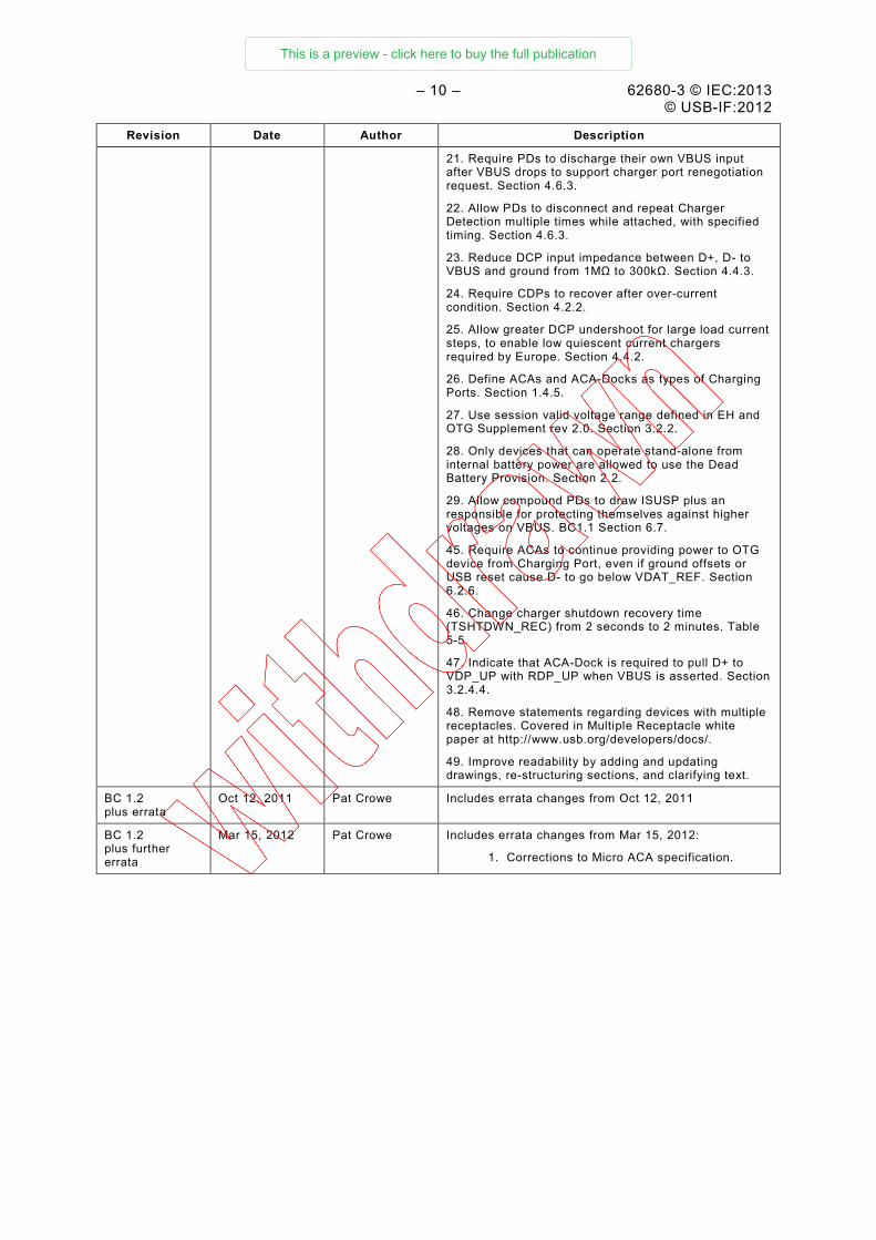
Revision Date Author Description
21. Require PDs to discharge their own VBUS input after VBUS drops to support charger port renegotiation request. Section 4.6.3.
22. Allow PDs to disconnect and repeat Charger Detection multiple times while attached, with specified timing. Section 4.6.3.
23. Reduce DCP input impedance between D+, D- to VBUS and ground from 1MΩ to 300kΩ. Section 4.4.3.
24. Require CDPs to recover after over-current condition. Section 4.2.2.
25. Allow greater DCP undershoot for large load current steps, to enable low quiescent current chargers required by Europe. Section 4.4.2.
26. Define ACAs and ACA-Docks as types of Charging Ports. Section 1.4.5.
27. Use session valid voltage range defined in EH and OTG Supplement rev 2.0. Section 3.2.2.
28. Only devices that can operate stand-alone from internal battery power are allowed to use the Dead Battery Provision. Section 2.2.
29. Allow compound PDs to draw ISUSP plus an responsible for protecting themselves against higher voltages on VBUS. BC1.1 Section 6.7.
45. Require ACAs to continue providing power to OTG device from Charging Port, even if ground offsets or USB reset cause D- to go below VDAT_REF. Section 6.2.6.
46. Change charger shutdown recovery time (TSHTDWN_REC) from 2 seconds to 2 minutes. Table 5-5.
47. Indicate that ACA-Dock is required to pull D+ to VDP_UP with RDP_UP when VBUS is asserted. Section 3.2.4.4.
48. Remove statements regarding devices with multiple receptacles. Covered in Multiple Receptacle white paper at http://www.usb.org/developers/docs/.
49. Improve readability by adding and updating drawings, re-structuring sections, and clarifying text.
BC 1.2 plus errata
Oct 12, 2011 Pat Crowe Includes errata changes from Oct 12, 2011
BC 1.2 plus further errata
Mar 15, 2012 Pat Crowe Includes errata changes from Mar 15, 2012:
1. Corrections to Micro ACA specification.
This is a preview - click here to buy the full publication

62680-3 © IEC:2013 – 11 – © USB-IF:2012
Acronyms ACA Accessory Charger Adapter CDP Charging Downstream Port DBP Dead Battery Provision DCD Data Contact Detect DCP Dedicated Charging Port FS Full Speed HS High-Speed LS Low-Speed OTG On-The-Go PC Personal Computer PD Portable Device PHY Physical Layer Interface for High-Speed USB PS2 Personal System 2 SDP Standard Downstream Port SRP Session Request Protocol TPL Targeted Peripheral List USB Universal Serial Bus USBCV USB Command Verifier USB-IF USB Implementers Forum VBUS Voltage line of the USB interface
This is a preview - click here to buy the full publication

– 12 – 62680-3 © IEC:2013 © USB-IF:2012
1 Introduction
1.1 Scope
The Battery Charging Working Group is chartered with creating specifications that define limits as well as detection, control and reporting mechanisms to permit devices to draw current in excess of the USB 2.0 specification for charging and/or powering up from dedicated chargers, hosts, hubs and charging downstream ports. These mechanisms are backward compatible with USB 2.0 compliant hosts and peripherals.
1.2 Background
The USB ports on personal computers are convenient places for Portable Devices (PDs) to draw current for charging their batteries. This convenience has led to the creation of USB Chargers that simply expose a USB standard-A receptacle. This allows PDs to use the same USB cable to charge from either a PC or from a USB Charger.
If a PD is attached to a USB host or hub, then the USB 2.0 specification requires that after connecting, a PD must draw less than:
• 2.5 mA average if the bus is suspended
• 100 mA if bus is not suspended and not configured
• 500 mA if bus is not suspended and configured for 500 mA
If a PD is attached to a Charging Port, (i.e. CDP, DCP, ACA-Dock or ACA), then it is allowed to draw IDEV_CHG without having to be configured or follow the rules of suspend.
In order for a PD to determine how much current it is allowed to draw from an upstream USB port, there need to be mechanisms that allow the PD to distinguish between a Standard Downstream Port and a Charging Port. This specification defines just such mechanisms.
Since PDs can be attached to USB chargers from various manufacturers, it is important that all provide an acceptable user experience. This specification defines the requirements for a compliant USB charger, which is referred to in this spec as a USB Charger.
If a PD has a Dead or Weak Battery, then the Connect Timing Engineering Change Notice (ECN) issued by the USB-IF on the USB 2.0 spec allows that device to draw up to IUNIT while attached but not connected. The conditions associated with this ECN are contained in Section 2 of this specification, and are referred to as the Dead Battery Provision (DBP).
1.3 Reference Documents
The following specifications contain information relevant to the Battery Charging Specification.
• OTG and Embedded Host Supplement, Revision 2.0
• USB 2.0 Specification
• USB 3.0 Specification
1.4 Definitions of Terms
This section contains definitions for some of the terms used in this specification.
1.4.1 Accessory Charger Adaptor
An Accessory Charger Adaptor (ACA) is an adaptor which allows a single USB port to be attached to both a charger and another device at the same time.
This is a preview - click here to buy the full publication

– 64 – 62680-3 © CEI:2013 © USB-IF:2012
COMMISSION ÉLECTROTECHNIQUE INTERNATIONALE
____________
INTERFACES DE BUS UNIVERSEL EN SÉRIE
POUR LES DONNÉES ET L'ALIMENTATION ÉLECTRIQUE –
Partie 3: Spécification de chargement des batteries USB, révision 1.2
AVANT-PROPOS 1) La Commission Electrotechnique Internationale (CEI) est une organisation mondiale de normalisation
composée de l'ensemble des comités électrotechniques nationaux (Comités nationaux de la CEI). La CEI a pour objet de favoriser la coopération internationale pour toutes les questions de normalisation dans les domaines de l'électricité et de l'électronique. A cet effet, la CEI – entre autres activités – publie des Normes internationales, des Spécifications techniques, des Rapports techniques, des Spécifications accessibles au public (PAS) et des Guides (ci-après dénommés "Publication(s) de la CEI"). Leur élaboration est confiée à des comités d'études, aux travaux desquels tout Comité national intéressé par le sujet traité peut participer. Les organisations internationales, gouvernementales et non gouvernementales, en liaison avec la CEI, participent également aux travaux. La CEI collabore étroitement avec l'Organisation Internationale de Normalisation (ISO), selon des conditions fixées par accord entre les deux organisations.
2) Les décisions ou accords officiels de la CEI concernant les questions techniques représentent, dans la mesure du possible, un accord international sur les sujets étudiés, étant donné que les Comités nationaux de la CEI intéressés sont représentés dans chaque comité d’études.
3) Les Publications de la CEI se présentent sous la forme de recommandations internationales et sont agréées comme telles par les Comités nationaux de la CEI. Tous les efforts raisonnables sont entrepris afin que la CEI s'assure de l'exactitude du contenu technique de ses publications; la CEI ne peut pas être tenue responsable de l'éventuelle mauvaise utilisation ou interprétation qui en est faite par un quelconque utilisateur final.
4) Dans le but d'encourager l'uniformité internationale, les Comités nationaux de la CEI s'engagent, dans toute la mesure possible, à appliquer de façon transparente les Publications de la CEI dans leurs publications nationales et régionales. Toutes divergences entre toutes Publications de la CEI et toutes publications nationales ou régionales correspondantes doivent être indiquées en termes clairs dans ces dernières.
5) La CEI elle-même ne fournit aucune attestation de conformité. Des organismes de certification indépendants fournissent des services d'évaluation de conformité et, dans certains secteurs, accèdent aux marques de conformité de la CEI. La CEI n'est responsable d'aucun des services effectués par les organismes de certification indépendants.
6) Tous les utilisateurs doivent s'assurer qu'ils sont en possession de la dernière édition de cette publication.
7) Aucune responsabilité ne doit être imputée à la CEI, à ses administrateurs, employés, auxiliaires ou mandataires, y compris ses experts particuliers et les membres de ses comités d'études et des Comités nationaux de la CEI, pour tout préjudice causé en cas de dommages corporels et matériels, ou de tout autre dommage de quelque nature que ce soit, directe ou indirecte, ou pour supporter les coûts (y compris les frais de justice) et les dépenses découlant de la publication ou de l'utilisation de cette Publication de la CEI ou de toute autre Publication de la CEI, ou au crédit qui lui est accordé.
8) L'attention est attirée sur les références normatives citées dans cette publication. L'utilisation de publications référencées est obligatoire pour une application correcte de la présente publication.
9) L’attention est attirée sur le fait que certains des éléments de la présente Publication de la CEI peuvent faire l’objet de droits de brevet. La CEI ne saurait être tenue pour responsable de ne pas avoir identifié de tels droits de brevets et de ne pas avoir signalé leur existence.
La Norme internationale CEI 62680-3 a été établie par le domaine technique 14: Interfaces et méthodes de mesure pour les équipements d'ordinateur personnel, du comité d'études 100 de la CEI: Systèmes et appareils audio, vidéo et multimédia.
Le texte de la présente norme est issu de documents élaborés par l'USB Implementers Forum (USB-IF). Les règles structurelles et éditoriales utilisées dans la présente publication reflètent les pratiques en vigueur au sein de l'organisme responsable de sa soumission.
This is a preview - click here to buy the full publication

62680-3 © CEI:2013 – 65 – © USB-IF:2012
Le texte de la présente norme est issu des documents suivants:
FDIS Rapport de vote
100/2157/FDIS 100/2190/RVD
Le rapport de vote indiqué dans le tableau ci-dessus donne toute information sur le vote ayant abouti à l'approbation de cette norme.
Afin d'éviter toute corruption des Figures, les originaux de la version anglaise ont été inclus dans la version française de la présente norme. Toutefois, pour les besoins des utilisateurs de la version française, une traduction du texte anglais a été ajoutée sous forme d'un tableau sous chaque Figure. A noter que ces "Légendes" ne contiennent aucune information supplémentaire par rapport à l'original anglais.
Une liste de toutes les parties de la série des CEI 62680, publiées sous le titre général Interfaces de bus universel en série pour les données et l'alimentation électrique est disponible sur le site internet de la CEI.
Le comité a décidé que le contenu de cette publication ne sera pas modifié avant la date de stabilité indiquée sur le site Web de la CEI sous http://webstore.iec.ch dans les données relatives à la publication recherchée. A cette date, la publication sera
• reconduite, • supprimée, • remplacée par une édition révisée, ou • amendée.
IMPORTANT – Le logo "colour inside" qui se trouve sur la page de couverture de cette publication indique qu'elle contient des couleurs qui sont considérées comme utiles à une bonne compréhension de son contenu. Les utilisateurs devraient, par conséquent, imprimer cette publication en utilisant une imprimante couleur.
This is a preview - click here to buy the full publication
– 66 – 62680-3 © CEI:2013 © USB-IF:2012
INTRODUCTION
La série CEI 62680 est issue d'une série de spécifications initialement établies par l'USB Implementers Forum (USB-IF). Ces spécifications ont été soumises à la CEI dans le cadre d'un accord particulier conclu entre la CEI et l'USB-IF.
L'USB Implementers Forum, Inc. (USB-IF) est une entreprise à but non lucratif fondée par le groupe de sociétés responsable de l'établissement de la spécification de bus universel en série . L'USB-IF a été créée dans le but de proposer un organisme et un forum à même de favoriser la progression et l'adoption de la technologie USB. Le Forum contribue au développement de périphériques (appareils) USB compatibles de qualité supérieure. Il met également en avant les avantages de la technologie USB, ainsi que la qualité des produits qui réussissent les essais de conformité.
TOUTES LES SPÉCIFICATIONS USB VOUS SONT FOURNIES "TELLES QUELLES" SANS AUCUNE GARANTIE DE QUELQUE SORTE QUE CE SOIT, Y COMPRIS LES GARANTIES DE QUALITÉ MARCHANDE, DE NON-VIOLATION OU D'ADÉQUATION À UN USAGE PARTICULIER. L'USB IMPLEMENTERS FORUM ET LES AUTEURS DES SPÉCIFICATIONS USB DÉCLINENT TOUTE RESPONSABILITÉ, Y COMPRIS LA VIOLATION DES DROITS D'AUTEUR, CONCERNANT L'UTILISATION, LA MISE EN APPLICATION OU LES INFORMATIONS DE LA PRÉSENTE SPÉCIFICATION. LA DISPOSITION DE SPÉCIFICATIONS USB NE SAURAIT VOUS ACCORDER UNE LICENCE, EXPLICITE OU IMPLICITE, PAR ESTOPPEL OU DE TOUTE AUTRE FAÇON, À DES DROITS DE PROPRIÉTE INTELLECTUELLE. La conclusion d'accords USB Adopters Agreements peut cependant permettre à une société signataire de prendre part à un accord de licence réciproque et libre de redevance sur des produits compatibles. Pour plus d'informations, rendez-vous sur: http://www.usb.org/developers/docs/ http://www.usb.org/developers/devclass_docs#approved
LA CEI NE PREND AUCUNE POSITION QUANT À SAVOIR S'IL VOUS EST RECOMMANDÉ DE CONCLURE TOUT ACCORD DES ADOPTANTS DE L'USB OU DE PARTICIPER À L'USB IMPLEMENTERS FORUM." La présente série traite des interfaces de bus universel en série pour les données et l'alimentation électrique et est composée des parties suivantes:
CEI 62680-1, Interfaces de bus universel en série pour les données et l'alimentation électrique – Partie 1: Spécification du bus universel en série, révision 2.0 CEI 62680-2, Interfaces de bus universel en série pour les données et l'alimentation électrique – Partie 2: Bus universel en série – Spécification des câbles et des connecteurs Micro-USB, révision 1.01 CEI 62680-3, Interfaces de bus universel en série pour les données et l'alimentation électrique – Partie 3: Spécification de chargement des batteries USB, révision 1.2 CEI 62680-4, Interfaces de bus universel en série pour les données et l'alimentation électrique – Partie 4: Document des classes des câbles et des connecteurs de bus universel en série, révision 2.0 La présente partie de la série CEI 62680 se compose de différentes parties distinctes:
• le corps du texte, qui correspond à la spécification initiale et l'ensemble des ECN et des errata développés par l'USB-IF.
This is a preview - click here to buy the full publication

62680-3 © CEI:2013 – 67 – © USB-IF:2012
SOMMAIRE
1 Introduction .................................................................................................................... 74 1.1 Domaine d'application ........................................................................................... 74 1.2 Contexte ............................................................................................................... 74 1.3 Documents de référence ....................................................................................... 74 1.4 Définitions de termes............................................................................................. 75
1.4.1 Adaptateur de chargeur auxiliaire .............................................................. 75 1.4.2 ACA-Dock.................................................................................................. 75 1.4.3 Différence entre "relier" et "connecter" ...................................................... 75 1.4.4 Port en aval de chargement ....................................................................... 75 1.4.5 Port de chargement ................................................................................... 75 1.4.6 Seuil de décharge de batterie .................................................................... 75 1.4.7 Port de chargement dédié .......................................................................... 76 1.4.8 Port en aval ............................................................................................... 76 1.4.9 ACA micro ................................................................................................. 76 1.4.10 Appareil portatif ......................................................................................... 76 1.4.11 Courant assigné ........................................................................................ 76 1.4.12 ACA standard ............................................................................................ 76 1.4.13 Port en aval normalisé ............................................................................... 76 1.4.14 Chargeur USB ........................................................................................... 76 1.4.15 Seuil de batterie faible ............................................................................... 77
1.5 Valeurs des paramètres ........................................................................................ 77 1.6 Considérations relatives aux appareils OTG .......................................................... 77 1.7 Considérations relatives aux ports SuperSpeed ..................................................... 77
2 Disposition relative aux batteries déchargées ................................................................. 77 2.1 Contexte ............................................................................................................... 77 2.2 DBP – Article non configuré................................................................................... 78 2.3 DBP – Article configuré ......................................................................................... 78
3 Détection de port de chargement .................................................................................... 80 3.1 Vue d'ensemble ..................................................................................................... 80 3.2 Matériel de détection de chargeur ......................................................................... 81
3.2.1 Vue d'ensemble ......................................................................................... 81 3.2.2 Détection de VBUS .................................................................................... 83 3.2.3 Détection de contact de données ............................................................... 83 3.2.4 Détection primaire ..................................................................................... 87 3.2.5 Détection secondaire ................................................................................. 96 3.2.6 Détection d'ACA ...................................................................................... 100
3.3 Algorithmes de détection de chargeur ................................................................. 102 3.3.1 Algorithme de batterie faible .................................................................... 102 3.3.2 Algorithme de charge suffisante .............................................................. 103
3.4 Déroulement de la détection de chargeur ............................................................ 105 3.4.1 Déroulement de la détection de contact de données ................................ 105 3.4.2 Déroulement de la détection, CDP ........................................................... 109
3.5 Courant à la masse et marges de bruit ................................................................ 110 4 Exigences relatives au port de chargement et à l'appareil portatif ................................. 110
4.1 Exigences relatives au port de chargement ......................................................... 111 4.1.1 Dépassement .......................................................................................... 111 4.1.2 Courant maximal ..................................................................................... 111
This is a preview - click here to buy the full publication
– 68 – 62680-3 © CEI:2013 © USB-IF:2012
4.1.3 Renégociation de la détection .................................................................. 111 4.1.4 Opération d'arrêt ..................................................................................... 111 4.1.5 Tension de panne .................................................................................... 111 4.1.6 Ports multiples ......................................................................................... 111
4.2 Port en aval de chargement ................................................................................. 111 4.2.1 Plage d'exploitation exigée ...................................................................... 111 4.2.2 Opération d'arrêt ..................................................................................... 112 4.2.3 Sous-performance ................................................................................... 113 4.2.4 Signalisation de la détection .................................................................... 113 4.2.5 Connecteur .............................................................................................. 113
4.3 ACA-Dock ........................................................................................................... 113 4.3.1 Plage d'exploitation exigée ...................................................................... 113 4.3.2 Sous-performance ................................................................................... 113 4.3.3 Signalisation de la détection .................................................................... 113 4.3.4 Connecteur .............................................................................................. 113
4.4 Port de chargement dédié ................................................................................... 114 4.4.1 Plage d'exploitation exigée ...................................................................... 114 4.4.2 Sous-performance ................................................................................... 115 4.4.3 Signalisation de la détection .................................................................... 115 4.4.4 Connecteur .............................................................................................. 115
4.5 Adaptateur de chargeur auxiliaire ........................................................................ 115 4.5.1 Plage d'exploitation exigée ...................................................................... 115 4.5.2 Sous-performance ................................................................................... 116 4.5.3 Signalisation de la détection .................................................................... 116 4.5.4 Connecteur .............................................................................................. 116
4.6 Appareil portatif ................................................................................................... 116 4.6.1 Plage d'exploitation autorisée .................................................................. 116 4.6.2 Signalisation de la détection .................................................................... 117 4.6.3 Renégociation de la détection .................................................................. 118 4.6.4 Connecteur .............................................................................................. 118
5 Valeurs des paramètres ................................................................................................ 118 6 Adaptateur de chargeur auxiliaire ................................................................................. 123
6.1 Introduction ......................................................................................................... 123 6.2 ACA micro ........................................................................................................... 124
6.2.1 Ports d'un ACA micro .............................................................................. 124 6.2.2 Options de connectivité d'un ACA micro .................................................. 127 6.2.3 Architecture d'un ACA micro .................................................................... 128 6.2.4 Modes de fonctionnement d'un ACA micro ............................................... 128 6.2.5 Répercussions de la non prise en charge de la détection d'ACA micro .... 130 6.2.6 Exigences relatives à l'ACA micro ........................................................... 130 6.2.7 Diagramme d'états d'un appareil portatif .................................................. 131
6.3 ACA standard ...................................................................................................... 133 6.3.1 Ports d'un ACA standard ......................................................................... 133 6.3.2 Architecture d'un ACA standard ............................................................... 135 6.3.3 Modes de fonctionnement d'un ACA standard .......................................... 136 6.3.4 Répercussions de la non prise en charge de la détection d'ACA
standard .................................................................................................. 136 6.3.5 Exigences relatives à l'ACA standard ...................................................... 136
This is a preview - click here to buy the full publication
62680-3 © CEI:2013 – 69 – © USB-IF:2012
Recharge des batteries Spécification
(Y compris les errata et les ECN jusqu'au 15 mars 2012)
Révision 1.2 15 mars 2012
Copyright © 2012, USB Implementers Forum, Inc.
Tous droits réservés.
LE PRÉSENT DOCUMENT ACCORDE UNE LICENCE POUR LA REPRODUCTION DE LA PRÉSENTE SPÉCIFICATION POUR UN USAGE INTERNE UNIQUEMENT. LE PRÉSENT DOCUMENT N'ACCORDE NI NE VISE À ACCORDER AUCUNE AUTRE LICENCE, EXPRESSE OU IMPLICITE, PAR ESTOPPEL OU AUTRE.
USB-IF ET LES AUTEURS DE LA PRÉSENTE SPÉCIFICATION DÉCLINENT EXPRESSÉMENT TOUTE RESPONSABILITÉ DE VIOLATION DE DROITS DE PROPRIÉTÉ INTELLECTUELLE EN CE QUI CONCERNE LA MISE EN ŒUVRE DES INFORMATIONS CONTENUES DANS LA PRÉSENTE SPÉCIFICATION. EN OUTRE, USB-IF ET LES AUTEURS DE LA PRÉSENTE SPÉCIFICATION NE GARANTISSENT NI NE DÉCLARENT QUE LA OU LESDITES MISES EN ŒUVRE NE VIOLERONT PAS LES DROITS DE PROPRIÉTÉ INTELLECTUELLE DE TIERS.
LA PRÉSENTE SPÉCIFICATION EST FOURNIE "EN L'ÉTAT", SANS GARANTIE, EXPRESSE OU IMPLICITE, LÉGALE OU AUTRE. TOUTES LES GARANTIES SONT EXPRESSÉMENT EXCLUES. LE PRÉSENT DOCUMENT N'OFFRE AUCUNE GARANTIE DE QUALITÉ MARCHANDE, AUCUNE GARANTIE DE NON-VIOLATION, AUCUNE GARANTIE D'ADAPTATION À UN USAGE PARTICULIER NI AUCUNE GARANTIE ÉMANANT D'UNE PROPOSITION, D'UNE SPÉCIFICATION OU D'UN ÉCHANTILLON QUELCONQUES.
USB-IF ET LES MEMBRES D'USB-IF NE POURRONT EN AUCUN CAS ÊTRE REDEVABLES À UN TIERS DU COÛT D'ACQUISITION DE BIENS OU DE SERVICES DE REMPLACEMENT, D'UN MANQUE À GAGNER, D'UNE PRIVATION DE JOUISSANCE, D'UNE PERTE DE DONNÉES OU DE TOUT DOMMAGE ACCESSOIRE, CONSÉCUTIF, INDIRECT OU PARTICULIER, EN VERTU D'UN CONTRAT, D'UN DÉLIT, D'UNE GARANTIE OU AUTRE, ÉMANANT DE QUELQUE MANIÈRE QUE CE SOIT DE L'UTILISATION DE LA PRÉSENTE SPÉCIFICATION, QUE LEDIT TIERS AIT OU NON ÉTÉ AVISÉ AU PRÉALABLE DE LA POSSIBILITÉ DE TELS DOMMAGES.
This is a preview - click here to buy the full publication

– 70 – 62680-3 © CEI:2013 © USB-IF:2012
Collaborateurs
Mark Lai Allion Test Labs
Sammy Mbanta Astec Power
Abel Astley Broadcom
Kenneth Ma Broadcom
Shimon Elkayam Broadcom
Gaurav Singh Cypress
Dan Ellis DisplayLink
Graham Connolly Fairchild
Oscar Freitas Fairchild
Joel Silverman Kawasaki
Pat Crowe MQP Electronics
Juha Heikkila Nokia
Richard Petrie Nokia
Sten Carlsen Nokia
Jeroen Kleinpenning NXP Semiconductors
Terry Remple, Chair Qualcomm
Dave Haglan SMSC
Mark Bohm SMSC
Morgan Monks SMSC
Tim Knowlton SMSC
Morten Christiansen ST Ericsson
Nicolas Florenchie ST Ericsson
Shaun Reemeyer ST Ericsson
George Paparrizos Summit Microelectronics
Adam Burns Synopsys
Wei Ming Telecommunication Metrology Center of MII
Jean Picard Texas Instruments
Ivo Huber Texas Instruments
Pasi Palojarvi Texas Instruments
Steven Tom Texas Instruments
Ed Beeman USB-IF
Mark Paxson USB-IF
This is a preview - click here to buy the full publication

62680-3 © CEI:2013 – 71 – © USB-IF:2012
Historique de révision
Révision Date Auteur Description
BC1.0 8 mars 2007 Terry Remple Première version
BC1.1 15 avril 2009 Terry Remple Mise à jour de l'ensemble des sections. Ajout du protocole de détection de contact de données et de l'adaptateur de chargeur auxiliaire.
BC1.2 5 octobre 2010 Terry Remple
Adam Burns
Les points ci-dessous indiquent les modifications apportées entre la révision BC1.1 et la révision BC1.2. Les références à des sections, figures et tableaux ci-dessous se rapportent à la révision BC1.2, sauf indication expresse désignant la révision BC1.1.
1. Permettre aux DCP de fournir plus de 1,5 A. Permet aux PD (Portable Devices, appareils portables) dotés de chargeurs à découpage de puiser davantage d'énergie. Section 4.4.1.
2. Augmenter le courant minimal du CDP pour le porter à 1,5 A. Avant cette modification, les PD devaient puiser moins de 500 mA pour éviter que le CDP ne s'arrête. Tableau 5-2.
3. Indiquer que les limites ICDP max et IDCP max de 5 A proviennent de la spécification USB 2.0, et constituent des limites de sécurité. Tableau 5-2, note 1.
4. Permettre aux PD de puiser jusqu'à 1,5 A pendant la compression d'impulsion et le trafic HS. Supprimer les anciennes limites de 560 mA et de 900 mA, qui se rapportaient aux plages de mode commun HS. Section 3.5.
5. Exiger des CDP qu'ils prennent en charge 1,5 A pendant la compression d'impulsion et le trafic HS. Concerne la plage de mode commun du CDP. Section 3.5.
6. Ramener le courant maximal du PD de 1,8 A à 1,5 A pour éviter qu'il ne s'arrête lorsqu'il est relié au CDP. Tableau 5-2.
7. Renommer la station d'accueil ACA-Dock pour éviter toute confusion avec les autres types de station d'accueil.
8. Exiger d'ACA-Dock qu'il se différencie d'un ACA en activant VDM_SRC en période d'inactivité. Section 3.2.4.4.
9. Permettre au CDP de laisser VDM_SRC activé lorsque le périphérique n'est pas connecté. Section 3.2.4.2.
10. Supprimer ICHG_SHTDWN. Il s'agissait d'un courant de sortie max. recommandé pour les ports de chargement avec VBUS mise à la terre. BC1.1, Section 4.1.
11. Exiger de VDP_SRC qu'il ne ramène pas D+ en dessous de 2,2 V lorsque D+ est amenée à VDP_UP via RDP_UP. Exiger de VDM_SRC qu'il ne ramène pas D- en dessous de 2,2 V lorsque D- est tirée vers le haut. Exigé pour la prise en charge d'ACA-Dock. Tableau 5-1, notes 1 et 2.
12. Rendre la source de courant de la DCD facultative pour les PD. Section 3.2.3.
13. Rendre le délai d'attente DCD obligatoire pour les PD. Section 3.2.3.
14. Rendre la détection secondaire facultative pour les PD. Section 4.6.2.
15. Rendre l'algorithme de charge suffisante obligatoire pour les PD. Section 3.2.4.
16. Supprimer la détection résistive. BC1.1, Section 3.9.
This is a preview - click here to buy the full publication
– 72 – 62680-3 © CEI:2013 © USB-IF:2012
Révision Date Auteur Description
17. Modifier la plage d'exploitation exigée du PD afin d'inclure 4,5 V à 500 mA. Figure 4-3.
18. Permettre à tous les ports en aval de jouer le rôle de DCP. Section 4.1.3.
19. Exiger des PD qu'ils activent VDP_SRC ou RDP_PU lors de leur chargement à partir d'un DCP. Section 3.3.2.
20. Permettre aux chargeurs de renégocier le courant avec le PD en faisant chuter VBUS et en la rétablissant. Section 4.1.3.
21. Exiger des PD qu'ils déchargent leur entrée VBUS après la chute de VBUS afin de prendre en charge la demande de renégociation du port chargeur. Section 4.6.3.
22. Permettre aux PD de se déconnecter et de procéder à plusieurs détections de chargeur lorsqu'ils sont reliés, selon le déroulement spécifié. Section 4.6.3.
23. Ramener l'impédance d'entrée du DCP entre D+, D-à VBUS et la masse de 1 MΩ à 300 kΩ. Section 4.4.3.
24. Exiger la reprise des CDP après chaque condition de surintensité. Section 4.2.2.
25. Permettre une sous-performance du DCP supérieure pour les grands échelons de courant de charge afin d'activer les chargeurs à faible courant de repos exigés par l'Europe. Section 4.4.2.
26. Définir les ACA et les ACA-Dock comme étant des types de port de chargement. Section 1.4.5.
27. Utiliser la plage de tension de validation de session définie dans l'EH et dans le supplément OTG rév. 2.0. Section 3.2.2.
28. Seuls les appareils qui peuvent fonctionner de manière autonome grâce à l'énergie fournie par leur batterie interne sont autorisés à utiliser la disposition relative aux batteries déchargées. Section 2.2.
29. Permettre aux PD composés de puiser ISUSP plus un responsable pour se protéger des tensions supérieures sur VBUS. BC1.1, Section 6.7.
45. Exiger des ACA qu'ils continuent d'alimenter l'appareil OTG à l'aide du port de chargement, même si les différences de masse ou la réinitialisation du bus USB ramènent D- en dessous de VDAT_REF. Section 6.2.6.
46. Modifier le temps de reprise sur arrêt du chargeur (TSHTDWN_REC) pour le porter de 2 s à 2 min. Tableau 5-5.
47. Indiquer qu'ACA-Dock doit amener D+ à VDP_UP avec RDP_UP lorsque VBUS est établie. Section 3.2.4.4.
48. Supprimer les énoncés relatifs aux appareils dotés de plusieurs embases. Ce sujet est traité dans le livre blanc sur les appareils à plusieurs embases disponible sous http://www.usb.org/developers/docs/.
49. Améliorer la lisibilité en ajoutant des dessins et en mettant à jour les dessins existants, en restructurant les sections, et en clarifiant le texte.
BC 1.2 plus errata
12 octobre 2011 Pat Crowe Inclut les modifications d'errata depuis le 12 octobre 2011
BC 1.2 plus autres errata
15 mars 2012 Pat Crowe Inclut les modifications d'errata depuis le 15 mars 2012:
1. Corrections à la spécification micro ACA.
This is a preview - click here to buy the full publication

62680-3 © CEI:2013 – 73 – © USB-IF:2012
Acronymes ACA Accessory Charger Adapter (adaptateur de chargeur auxiliaire) CDP Charging Downstream Port (port en aval de chargement) DBP Dead Battery Provision (disposition relative aux batteries déchargées) DCD Data Contact Detect (détection de contact de données) DCP Dedicated Charging Port (port de chargement dédié) FS Full Speed (pleine vitesse) HS High Speed (grande vitesse) LS Low Speed (basse vitesse) OTG On-The-Go PC Personal Computer (ordinateur personnel) PD Portable Device (appareil portatif) PHY Physical Layer Interface for High-Speed USB (interface de couche physique pour
USB grande vitesse) PS2 Personal System (système personnel) 2 SDP Standard Downstream Port (port en aval normalisé) SRP Session Request Protocol (protocole de demande de session) TPL Targeted Peripheral List (liste des périphériques cibles) USB Universal Serial Bus (bus universel en série ) USBCV USB Command Verifier (vérificateur de commande USB) USB-IF USB Implementers Forum VBUS Voltage line of the USB interface (ligne de tension de l'interface USB)
This is a preview - click here to buy the full publication

– 74 – 62680-3 © CEI:2013 © USB-IF:2012
1 Introduction
1.1 Domaine d'application
Le groupe de travail Battery Charging est chargé de créer des spécifications définissant des limites ainsi que des mécanismes de détection, de contrôle et de rapports pour permettre à des appareils de puiser une quantité de courant supérieure à celle prévue par la spécification USB 2.0 pour se charger et/ou s'allumer à l'aide de chargeurs, d'hôtes, de concentrateurs et de ports en aval de chargement dédiés. Ces mécanismes sont rétrocompatibles avec les hôtes et périphériques compatibles USB 2.0.
1.2 Contexte
Les ports USB des ordinateurs personnels sont très pratiques puisqu'ils permettent aux appareils portatifs (PD) de puiser du courant pour charger leur batterie. Cette commodité a conduit à la création de chargeurs USB possédant tout simplement une embase USB normale A. Cela permet aux PD d'utiliser le même câble USB pour charger leur batterie à partir d'un PC ou d'un chargeur USB.
Si un PD est relié à un hôte ou un concentrateur USB, la spécification USB 2.0 exige qu'une fois connecté, ce PD puise moins de:
• 2,5 mA en moyenne si le bus est suspendu
• 100 mA si le bus n'est ni suspendu, ni configuré
• 500 mA si le bus n'est pas suspendu, mais configuré pour 500 mA
Si un PD est relié à un port de chargement (CDP, DCP, ACA-Dock ou ACA), il est autorisé à puiser IDEV_CHG sans être configuré ni respecter les règles de la suspension.
Pour qu'un PD détermine la quantité de courant qu'il est autorisé à puiser à partir d'un port USB en amont, il doit exister des mécanismes qui permettent à ce PD de faire la distinction entre un port en aval normalisé et un port de chargement. La présente spécification définit justement ces mécanismes.
Les PD peuvent être reliés aux chargeurs USB de divers fabricants; il est donc important que tous ces chargeurs offrent une expérience utilisateur acceptable. La présente spécification définit les exigences relatives à un chargeur USB conforme, qu'elle désigne sous le terme "Chargeur USB".
Si la batterie d'un PD est déchargée ou faible, la notice de modification technique (Engineering Change Notice, ECN) concernant le temps de connexion, publiée par l'USB-IF au sujet de la spécification USB 2.0, permet à cet appareil de puiser jusqu'à IUNIT lorsqu'il est relié mais pas connecté. Les conditions associées à cette ECN sont indiquées dans la Section 2 de la présente spécification et sont regroupées sous le terme "disposition relative aux batteries déchargées" (DBP).
1.3 Documents de référence
Les spécifications ci-dessous contiennent des informations pertinentes pour la spécification de chargement de batterie.
• OTG and Embedded Host Supplement, révision 2.0
• Spécification USB 2.0
• Spécification USB 3.0
This is a preview - click here to buy the full publication