ee 136 final presentation professor dr. zhou presented by: cynthia david
Post on 21-Dec-2015
217 views
TRANSCRIPT

EE 136 Final PresentationProfessor Dr. Zhou
Presented by:Cynthia David
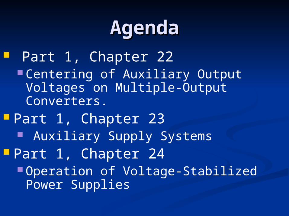
AgendaAgenda Part 1, Chapter 22
Centering of Auxiliary Output Voltages on Multiple-Output Converters.
Part 1, Chapter 23 Auxiliary Supply Systems
Part 1, Chapter 24 Operation of Voltage-Stabilized Power
Supplies
Centering Auxiliary Output Voltages Centering Auxiliary Output Voltages on Multiple-Output Converterson Multiple-Output Converters
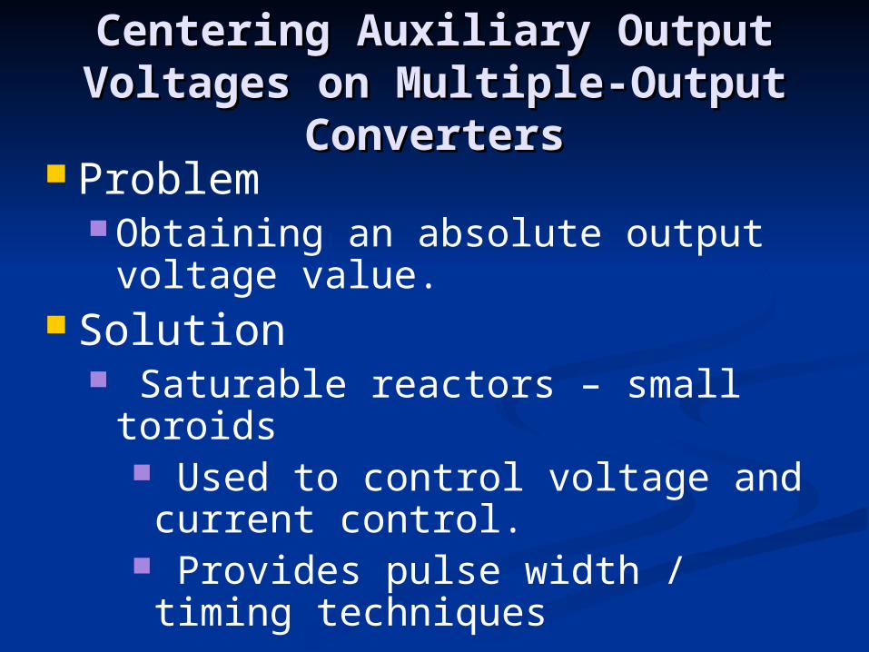
Problem Obtaining an absolute output voltage
value. Solution
Saturable reactors – small toroids Used to control voltage and current
control. Provides pulse width / timing
techniques
Centering Auxiliary Output Voltages Centering Auxiliary Output Voltages on Multiple-Output Converterson Multiple-Output Converters
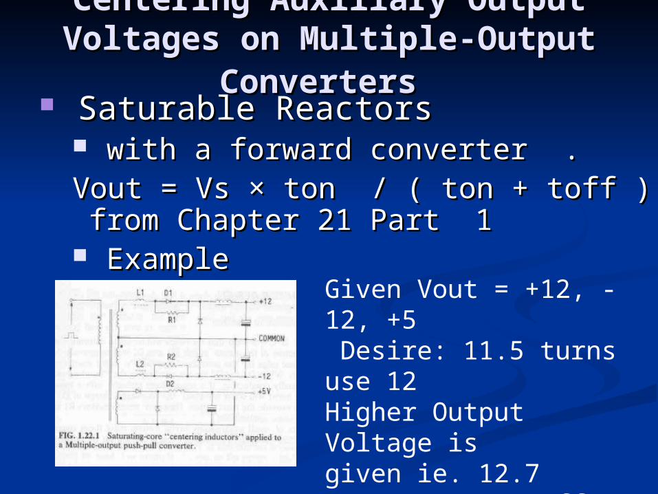
Saturable ReactorsSaturable Reactors with a forward converter .with a forward converter .Vout = Vs × ton / ( ton + toff ) from Chapter Vout = Vs × ton / ( ton + toff ) from Chapter
21 Part 121 Part 1 ExampleExample
Given Vout = +12, -12, +5 Desire: 11.5 turns use 12 Higher Output Voltage is given ie. 12.7 ton = 15 µs toff = 18 µs

Centering Auxiliary Output Voltages Centering Auxiliary Output Voltages on Multiple-Output Converterson Multiple-Output Converters
Saturable ReactorsSaturable Reactors td = ton – required V × ton / (actual Vout )
= 15 - (12*15) / (12.7) = .827 µs
td is delay time, ton is on cycle, Vs = Vout ( ton + toff) / ton = 27.9 V . td = Np × ∆B × Ae / (Vs) Np is the primary turns, ∆B difference in remanance flux
from flux density saturation. Ae is the effective area of the core. Given ∆B = .4
Ae = Vs × td / ( Np × ∆B ) assume Np = 1.

Centering Auxiliary Output Voltages Centering Auxiliary Output Voltages on Multiple-Output Converterson Multiple-Output Converters
Saturable ReactorsSaturable Reactors Ae = Vs × td / ( Np × ∆B ) assume Np = 1. = 27.9*.827 µs / (1 * .4) = 57.7 mm^2
Centering Auxiliary Output Voltages Centering Auxiliary Output Voltages on Multiple-Output Converterson Multiple-Output Converters
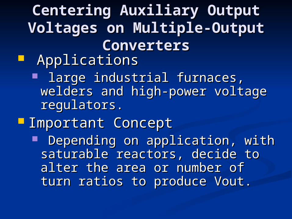
ApplicationsApplications large industrial furnaces, welders and large industrial furnaces, welders and
high-power voltage regulators.high-power voltage regulators. Important ConceptImportant Concept
Depending on application, with Depending on application, with saturable reactors, decide to alter the saturable reactors, decide to alter the area or number of turn ratios to produce area or number of turn ratios to produce Vout.Vout.

Auxiliary Supply Systems
Auxiliary Supply Systems Provide power for control Drive circuits within the main switch-mode
unit. Need to be common to input and output
lines. Safety factors must be given
Creepage distance, isolation requirementsCreepage distance, isolation requirements Auxiliary supply methods must be Auxiliary supply methods must be
consideredconsidered
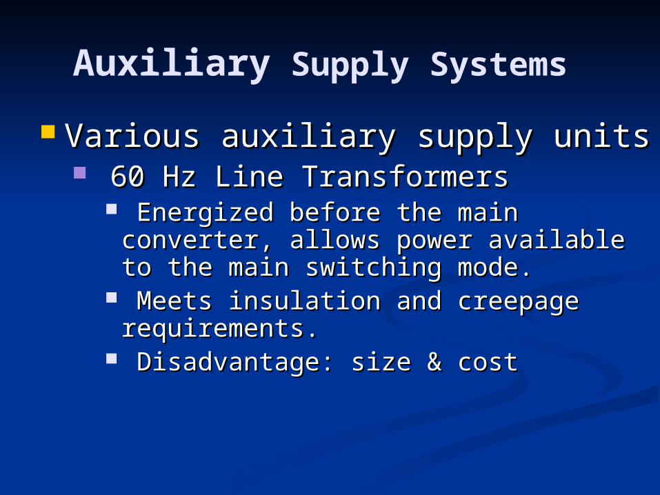
Auxiliary Supply Systems
Various auxiliary supply units Various auxiliary supply units 60 Hz Line Transformers 60 Hz Line Transformers
Energized before the main converter, allows Energized before the main converter, allows power available to the main switching mode. power available to the main switching mode.
Meets insulation and creepage requirements.Meets insulation and creepage requirements. Disadvantage: size & costDisadvantage: size & cost

Auxiliary Supply Systems
Auxiliary ConvertersAuxiliary Converters Two auxiliary power supplies from high Two auxiliary power supplies from high
frequency flyback converters.frequency flyback converters.
+ More efficient because energyIs returnted to the supply during Flyback period.
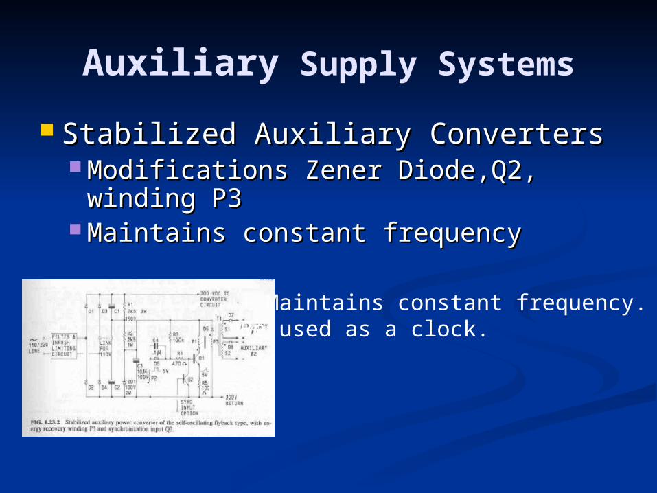
Auxiliary Supply Systems
Stabilized Auxiliary ConvertersStabilized Auxiliary Converters Modifications Zener Diode,Q2, winding Modifications Zener Diode,Q2, winding
P3P3 Maintains constant frequencyMaintains constant frequency
+ Maintains constant frequency. CanBe used as a clock.

Auxiliary Supply Systems
High-efficiency auxiliary supply.High-efficiency auxiliary supply. Includes a bridge rectifier supply the Includes a bridge rectifier supply the
converter & fan applicationconverter & fan application
+ Most efficient supply system+ Useful in 110-220V applications
Parallel Operation of Voltage-Parallel Operation of Voltage-Stabilized Power SuppliesStabilized Power Supplies
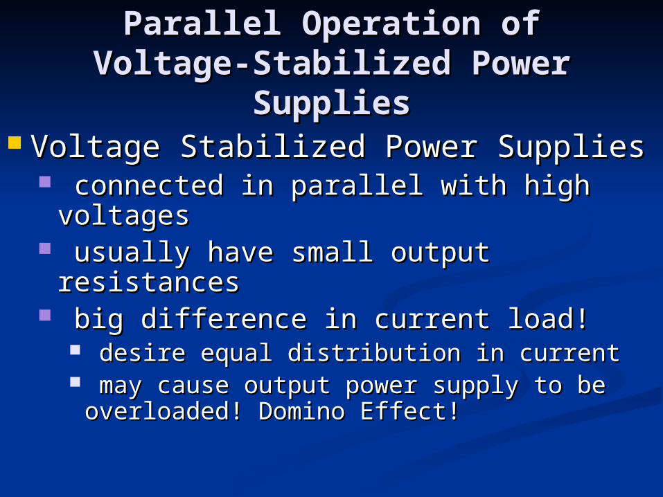
Voltage Stabilized Power Supplies Voltage Stabilized Power Supplies connected in parallel with high voltagesconnected in parallel with high voltages usually have small output resistancesusually have small output resistances big difference in current load!big difference in current load!
desire equal distribution in currentdesire equal distribution in current may cause output power supply to be may cause output power supply to be
overloaded! Domino Effect!overloaded! Domino Effect!

Parallel Operation of Voltage-Parallel Operation of Voltage-Stabilized Power SuppliesStabilized Power Supplies
Configurations of Power SuppliesConfigurations of Power Supplies Master Slave OperationMaster Slave Operation
Master controls the parallel supplies. P-Master controls the parallel supplies. P-terminal and Transistor 3 control currentterminal and Transistor 3 control current
KEY POINTS+ Similar output current - 20% Accurate - Limited to the number of supplies - If Master Fails, other units follow
Parallel Operation of Voltage-Parallel Operation of Voltage-Stabilized Power SuppliesStabilized Power Supplies
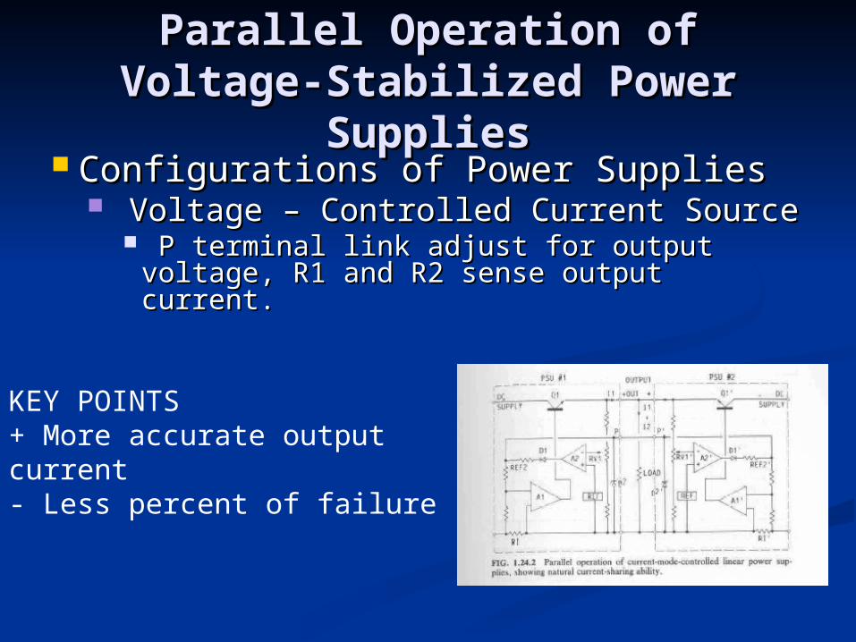
Configurations of Power SuppliesConfigurations of Power Supplies Voltage – Controlled Current SourceVoltage – Controlled Current Source
P terminal link adjust for output voltage, R1 P terminal link adjust for output voltage, R1 and R2 sense output current. and R2 sense output current.
KEY POINTS+ More accurate output current- Less percent of failure
Parallel Operation of Voltage-Parallel Operation of Voltage-Stabilized Power SuppliesStabilized Power Supplies
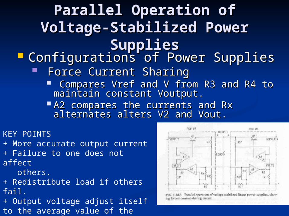
Configurations of Power SuppliesConfigurations of Power Supplies Force Current SharingForce Current Sharing
Compares Vref and V from R3 and R4 to maintain Compares Vref and V from R3 and R4 to maintain constant Voutput.constant Voutput.
A2 compares the currents and Rx alternates alters A2 compares the currents and Rx alternates alters V2 and Vout.V2 and Vout.
KEY POINTS+ More accurate output current+ Failure to one does not affect others.+ Redistribute load if others fail.+ Output voltage adjust itself to the average value of the independent units.
Parallel Operation of Voltage-Parallel Operation of Voltage-Stabilized Power SuppliesStabilized Power Supplies
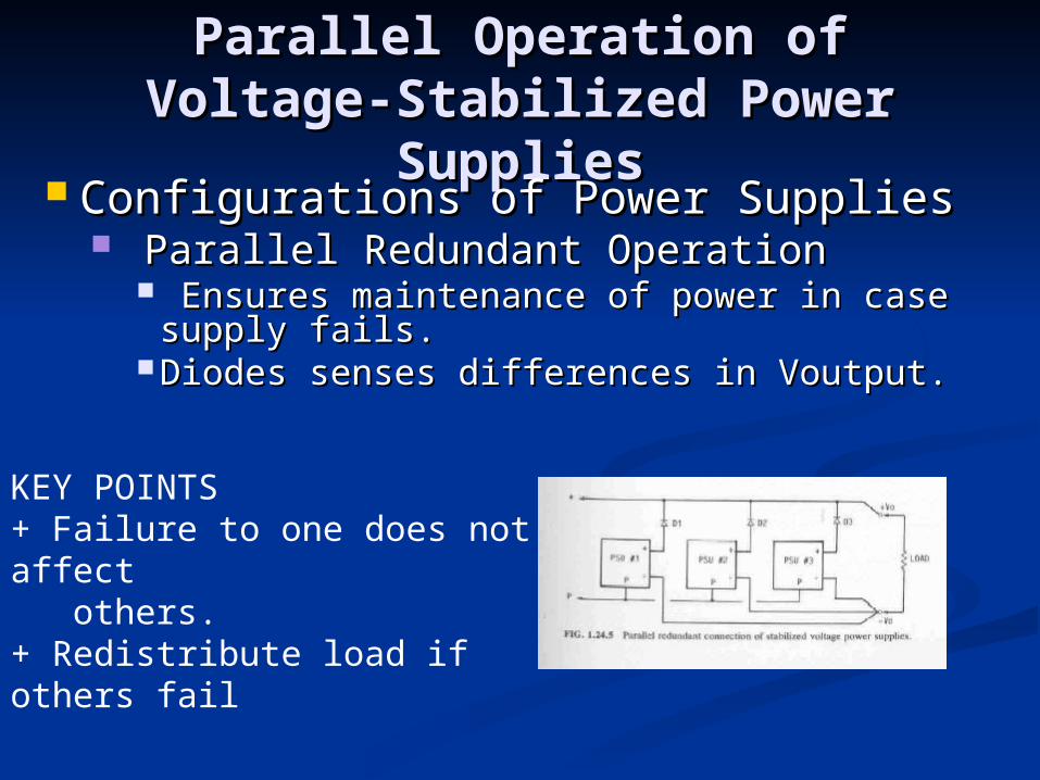
Configurations of Power SuppliesConfigurations of Power Supplies Parallel Redundant OperationParallel Redundant Operation
Ensures maintenance of power in case Ensures maintenance of power in case supply fails. supply fails.
Diodes senses differences in Voutput.Diodes senses differences in Voutput.
KEY POINTS+ Failure to one does not affect others.+ Redistribute load if others fail
ConclusionConclusion
ReviewReview Centering of Auxiliary Output Voltages on Centering of Auxiliary Output Voltages on
Multiple-Output ConvertersMultiple-Output Converters Auxiliary Supply SystemsAuxiliary Supply Systems Parallel Operation of Voltage Stabilized Power Parallel Operation of Voltage Stabilized Power
Supplies.Supplies.