ee 308 spring 2014 hc12 addressing modes o inherent ...erives/308_14/lecture4_s14.pdf · ee 308...
TRANSCRIPT

EE 308 Spring 2014
• HC12 Addressing Modes o Inherent, Extended, Direct, Immediate, Indexed, and
Relative Modes o Summary of MC9S12 Addressing Modes o Using X and Y registers as pointers o How to tell which branch instruction to use
• Instruction coding and execution o How to hand assemble a program o Number of cycles and time taken to execute an
MC9S12 program
The MC9S12 has 6 addressing modes
Most of the HC12’s instructions access data in memoryThere are several ways for the HC12 to determine which address to access
Effective address:Memory address used by instruction (all modes except INH)
Addressing mode:How the MC9S12 calculates the effective address
EE 308 Spring 2014
HC12 ADDRESSING MODES:
INH Inherent
IMM Immediate
DIR Direct
EXT Extended
REL Relative (used only with branch instructions)
IDX Indexed (won’t study indirect indexed mode)
EE 308 Spring 2014
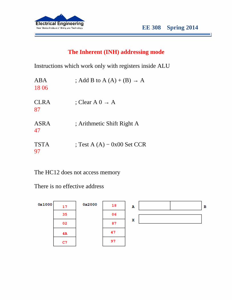
The Inherent (INH) addressing mode
Instructions which work only with registers inside ALU
ABA ; Add B to A (A) + (B) → A18 06
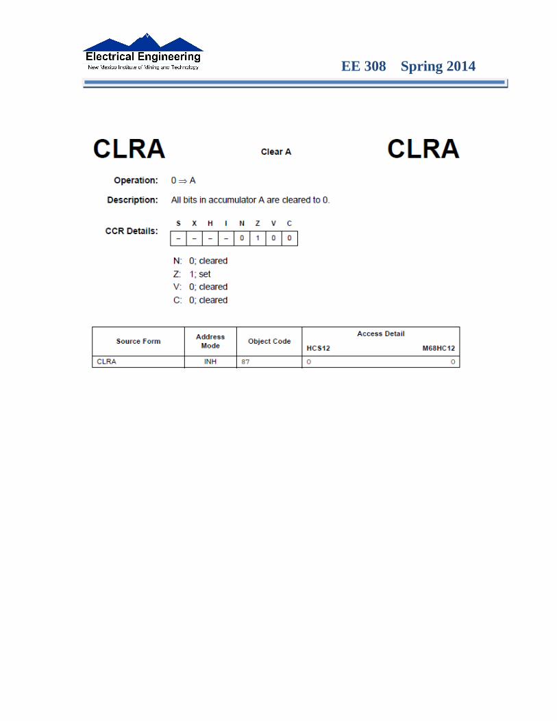
CLRA ; Clear A 0 → A87
ASRA ; Arithmetic Shift Right A47
TSTA ; Test A (A) − 0x00 Set CCR97
The HC12 does not access memory
There is no effective address
EE 308 Spring 2014
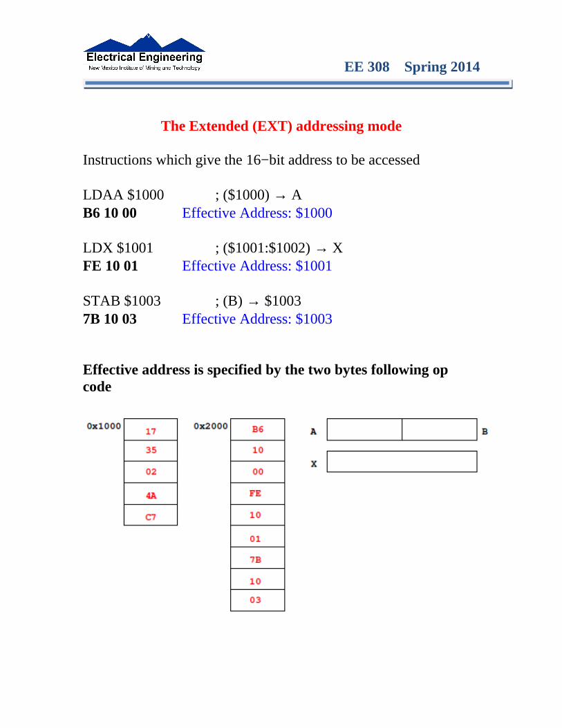
The Extended (EXT) addressing mode
Instructions which give the 16−bit address to be accessed
LDAA $1000 ; ($1000) → AB6 10 00 Effective Address: $1000
LDX $1001 ; ($1001:$1002) → XFE 10 01 Effective Address: $1001
STAB $1003 ; (B) → $10037B 10 03 Effective Address: $1003
Effective address is specified by the two bytes following op code
EE 308 Spring 2014
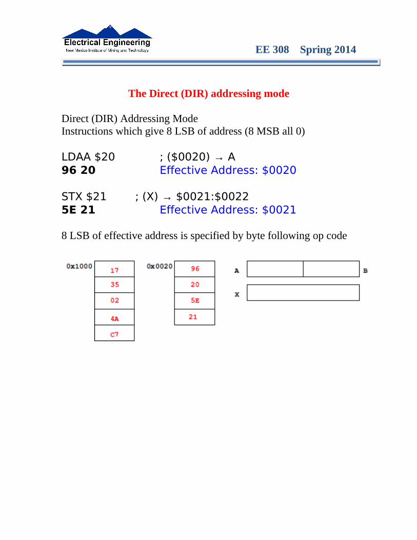
The Direct (DIR) addressing mode
Direct (DIR) Addressing ModeInstructions which give 8 LSB of address (8 MSB all 0)
LDAA $20 ; ($0020) → A96 20 Effective Address: $0020
STX $21 ; (X) → $0021:$00225E 21 Effective Address: $0021
8 LSB of effective address is specified by byte following op code
EE 308 Spring 2014
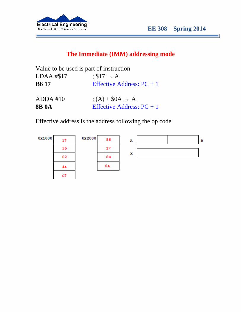
The Immediate (IMM) addressing mode
Value to be used is part of instructionLDAA #$17 ; $17 → AB6 17 Effective Address: PC + 1
ADDA #10 ; (A) + $0A → A8B 0A Effective Address: PC + 1
Effective address is the address following the op code

EE 308 Spring 2014
The Indexed (IDX, IDX1, IDX2) addressing mode
Effective address is obtained from X or Y register (or SP or PC)Simple Forms
LDAA 0,X ; Use (X) as address to get value to put in AA6 00 Effective address: contents of X
ADDA 5,Y ; Use (Y) + 5 as address to get value to add toAB 45 Effective address: contents of Y + 5
More Complicated Forms
INC 2,X− ; Post−decrement Indexed; Increment the number at address (X),; then subtract 2 from X
62 3E Effective address: contents of X
INC 4,+X ; Pre−increment Indexed; Add 4 to X; then increment the number at address (X)
62 23 Effective address: contents of X + 4

EE 308 Spring 2014
Different types of indexed addressing modes(Note: We will not discuss indirect indexed mode)
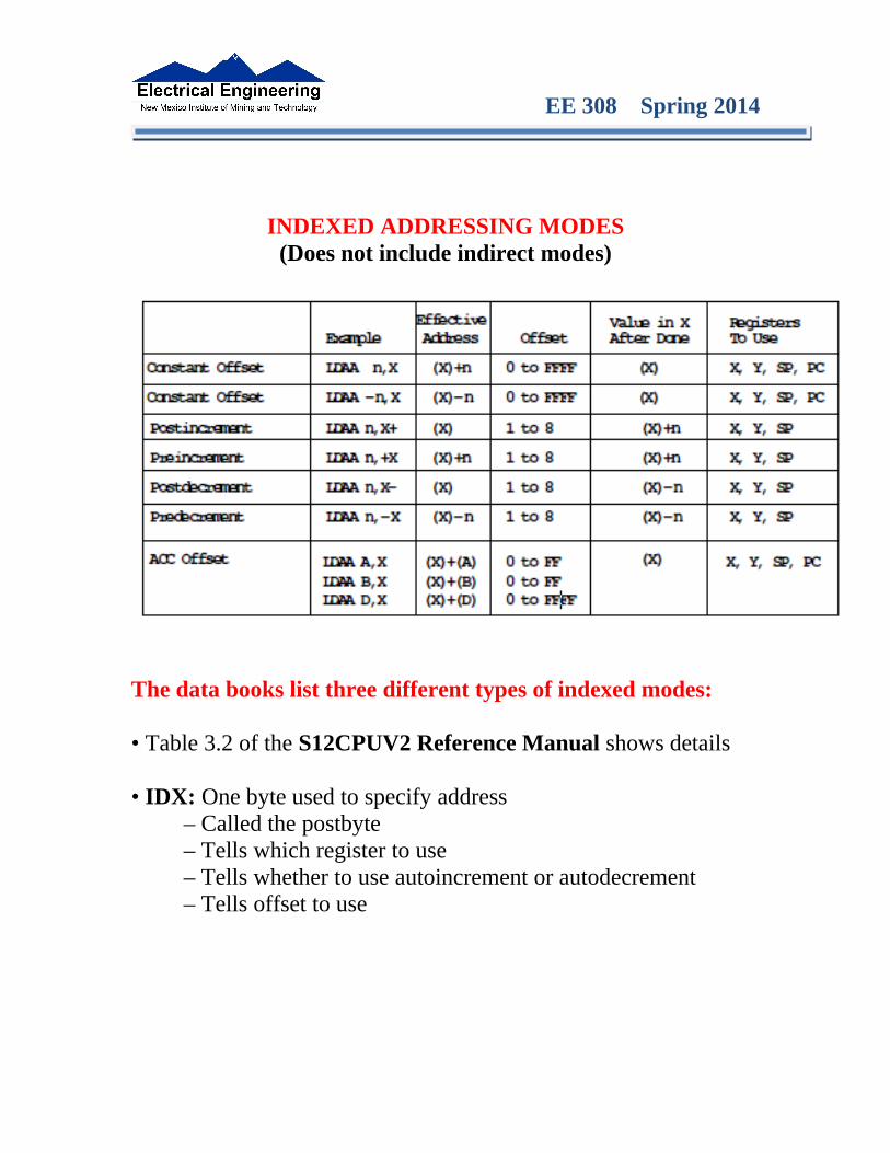
EE 308 Spring 2014
INDEXED ADDRESSING MODES(Does not include indirect modes)
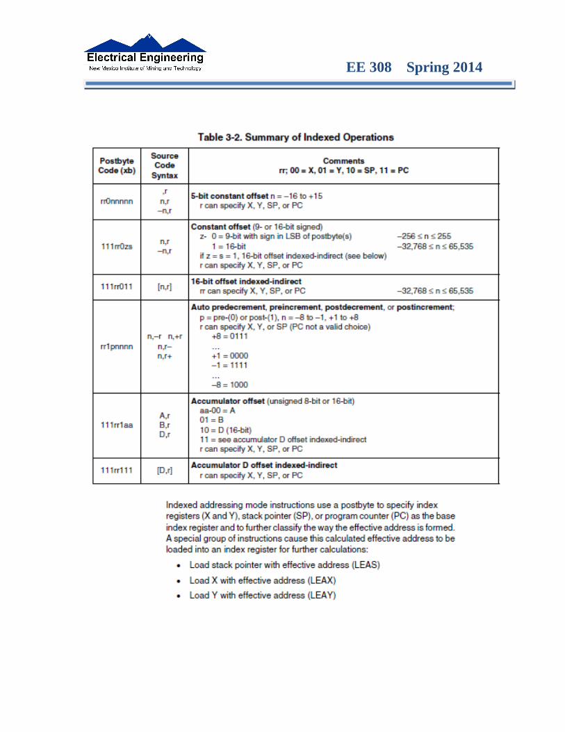
The data books list three different types of indexed modes:
• Table 3.2 of the S12CPUV2 Reference Manual shows details
• IDX: One byte used to specify address– Called the postbyte– Tells which register to use– Tells whether to use autoincrement or autodecrement– Tells offset to use
EE 308 Spring 2014
• IDX1: Two bytes used to specify address– First byte called the postbyte– Second byte called the extension– Postbyte tells which register to use, and sign of offset– Extension tells size of offset
• IDX2: Three bytes used to specify address– First byte called the postbyte– Next two bytes called the extension– Postbyte tells which register to use– Extension tells size of offset
EE 308 Spring 2014

EE 308 Spring 2014
Relative (REL) Addressing Mode
The relative addressing mode is used only in branch and long branch instructions.
Branch instruction: One byte following op code specifies how far to branch.
Treat the offset as a signed number; add the offset to the address following the current instruction to get the address of the instruction to branch to
(BRA) 20 35 PC + 2 + 0035 → PC
(BRA) 20 C7 PC + 2 + FFC7 → PC PC + 2 − 0039 → PC
Long branch instruction: Two bytes following op code specifies how far to branch.
Treat the offset as an unsigned number; add the offset to the address following the current instruction to get the address of the instruction to branch to
(LBEQ) 18 27 02 1A If Z == 1 then PC + 4 + 021A → PC If Z == 0 then PC + 4 → PC
When writing assembly language program, you don’t have to calculate offset. You indicate what address you want to go to, and the assembler calculates the offset
EE 308 Spring 2014
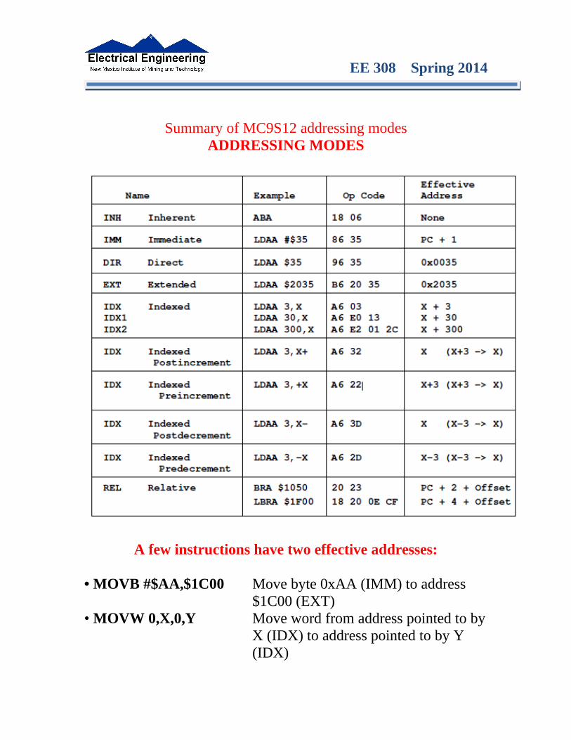
Summary of MC9S12 addressing modesADDRESSING MODES
A few instructions have two effective addresses:
• MOVB #$AA,$1C00 Move byte 0xAA (IMM) to address$1C00 (EXT)
• MOVW 0,X,0,Y Move word from address pointed to byX (IDX) to address pointed to by Y(IDX)
EE 308 Spring 2014
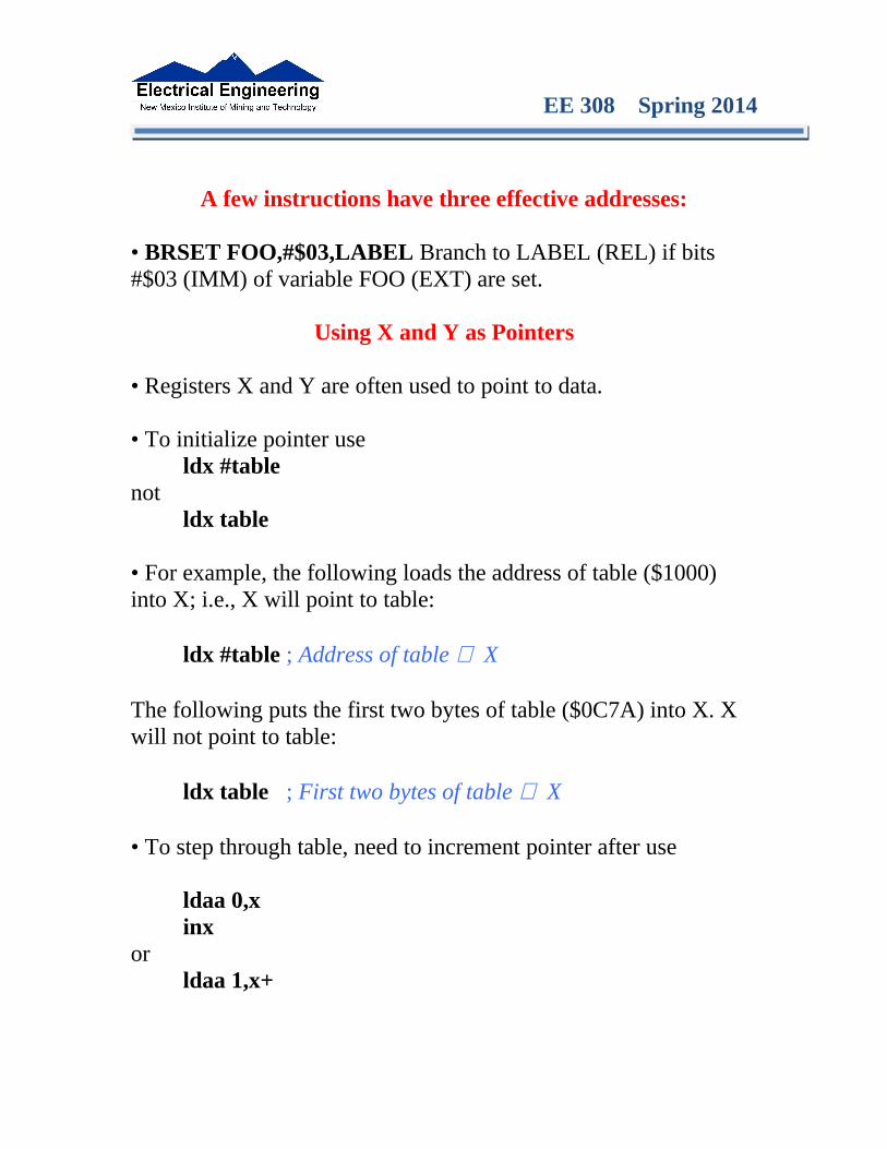
A few instructions have three effective addresses:
• BRSET FOO,#$03,LABEL Branch to LABEL (REL) if bits #$03 (IMM) of variable FOO (EXT) are set.
Using X and Y as Pointers
• Registers X and Y are often used to point to data.
• To initialize pointer useldx #table
notldx table
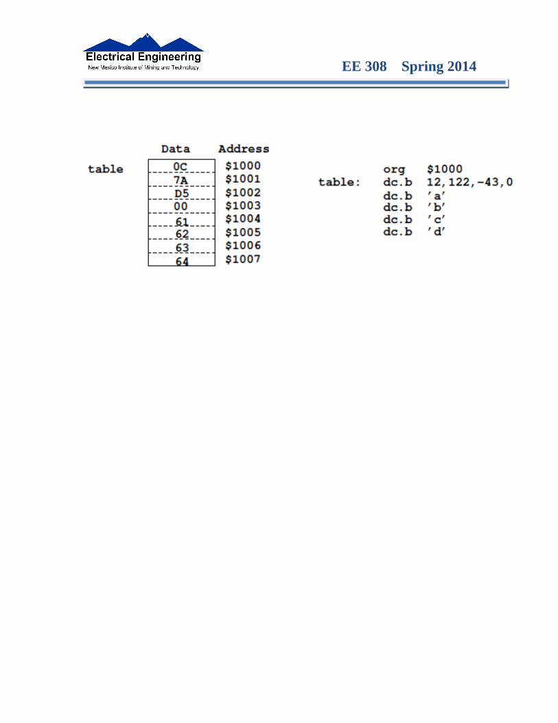
• For example, the following loads the address of table ($1000) into X; i.e., X will point to table:
ldx #table ; Address of table ⇒ X
The following puts the first two bytes of table ($0C7A) into X. X will not point to table:
ldx table ; First two bytes of table ⇒ X
• To step through table, need to increment pointer after use
ldaa 0,xinx
orldaa 1,x+
EE 308 Spring 2014

EE 308 Spring 2014
Which branch instruction should you use?
Branch if A > B
Is 0xFF > 0x00?
If unsigned, 0xFF = 255 and 0x00 = 0,so 0xFF > 0x00
If signed, 0xFF = −1 and 0x00 = 0,so 0xFF < 0x00
Using unsigned numbers: BHI (checks C bit of CCR)
Using signed numbers: BGT (checks V bit of CCR)
For unsigned numbers, use branch instructions which check C bit
For signed numbers, use branch instructions which check V bit
EE 308 Spring 2014
Hand Assembling a ProgramTo hand-assemble a program, do the following:
1. Start with the org statement, which shows where the first byte of the program will go into memory.(e.g., org $2000 will put the first instruction at address $2000.)
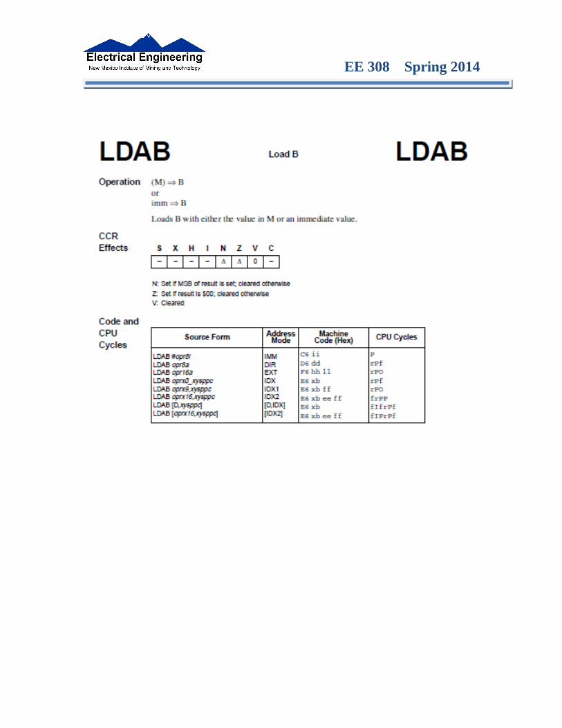
2. Look at the first instruction. Determine the addressing mode used.(e.g., ldab #10 uses IMM mode.)
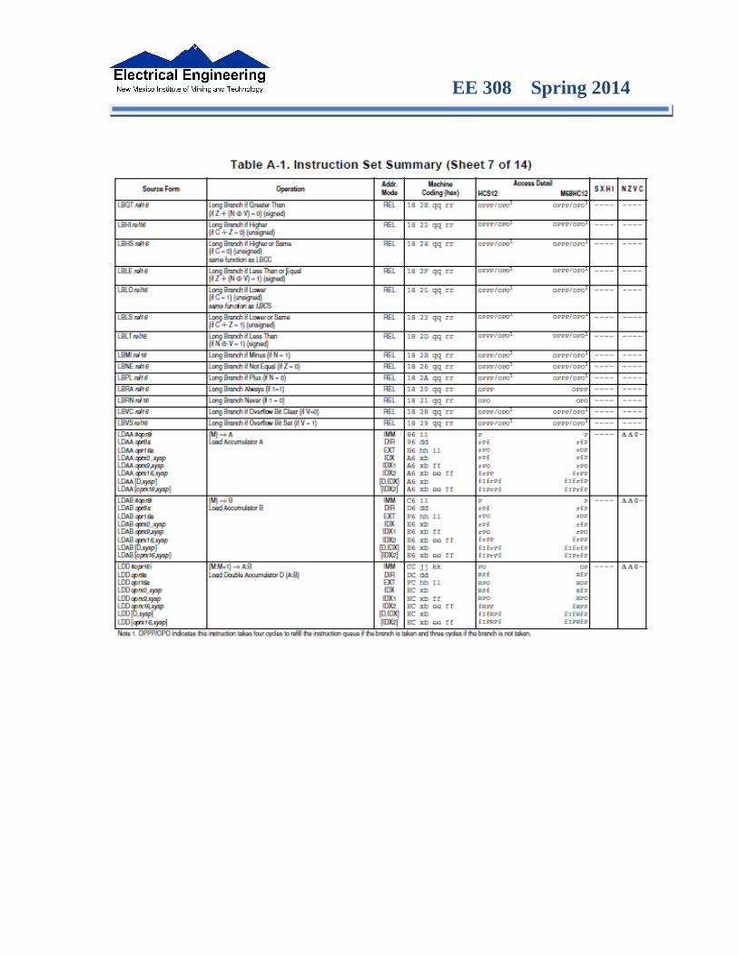
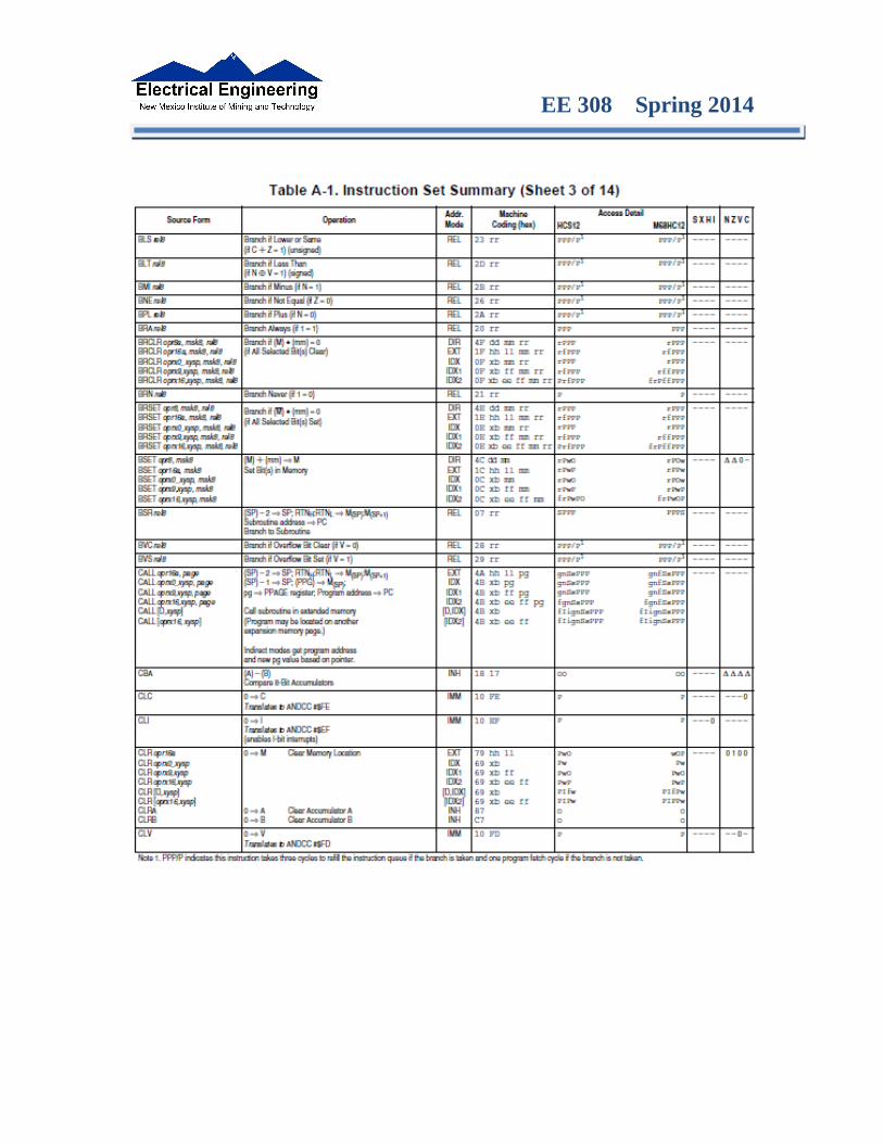
3. Look up the instruction in the MC9S12 S12CPUV2 Reference Manual, find the appropriate Addressing Mode, and the Object Code for that addressing mode. (e.g., ldab IMM has object code C6 ii.)
• Table A.1 of S12CPUV2 Reference Manual has a concise summary of the instructions, addressing modes, op-codes, and cycles.
4. Put in the object code for the instruction, and put in the appropriate operand. Be careful to convert decimal operands to hex operands if necessary. (e.g., ldab #10 becomes C6 0A.)
5. Add the number of bytes of this instruction to the address of the instruction to determine the address of the next instruction.(e.g., $2000 + 2 = $2002 will be the starting address of the next instruction.)

EE 308 Spring 2014
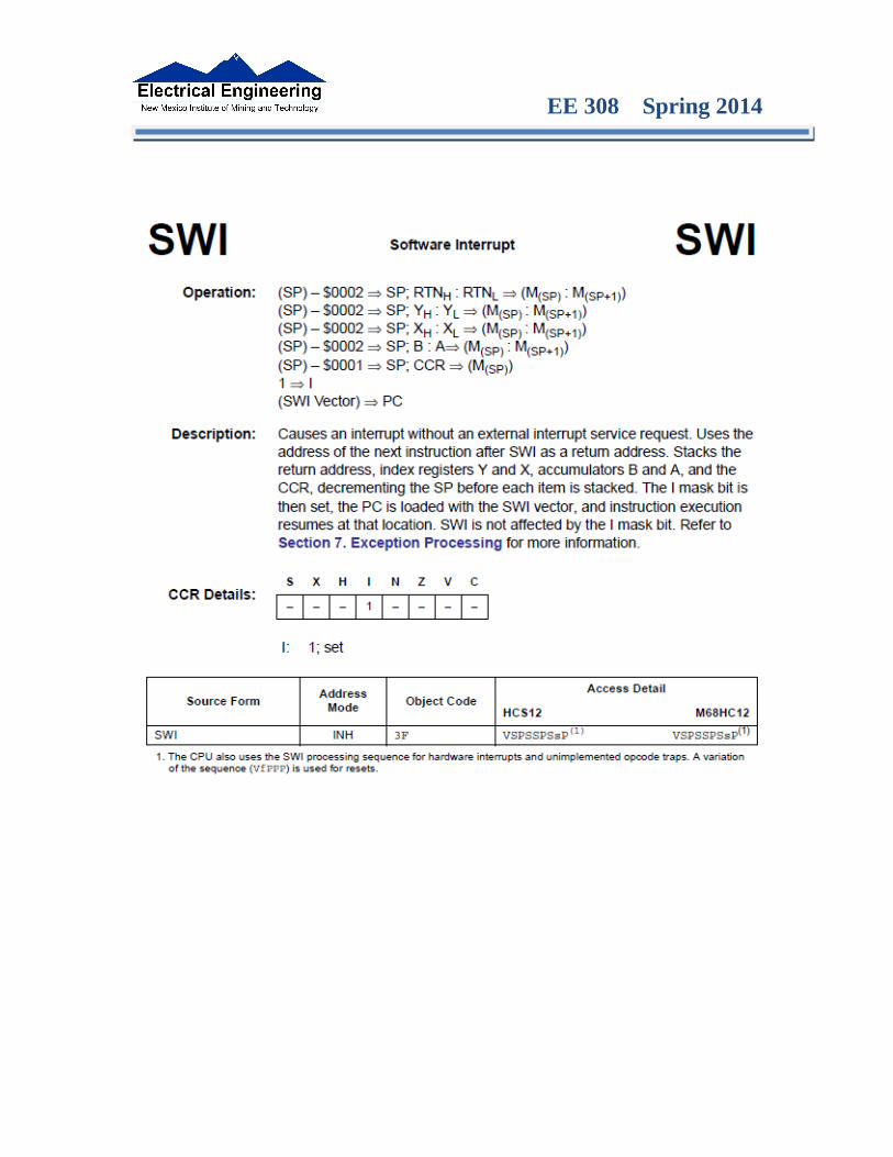
org $2000 ldab #10loop: clra dbne b,loop swi
Freescale HC12-Assembler (c) Copyright Freescale 1987-2010
Abs. Rel. Loc Obj. code Source line ---- ---- ------ --------- ----------- 1 1 2 2 0000 2000 prog: equ $2000 3 3 org prog 4 4 a002000 C60A ldab #10 5 5 a002002 87 loop: clra 6 6 a002003 0431 FC dbne b,loop 7 7 a002006 3F swi
EE 308 Spring 2014
EE 308 Spring 2014

EE 308 Spring 2014

EE 308 Spring 2014
MC9S12 Cycles
• 68HC12 works on 48 MHz clock
• A processor cycle takes 2 clock cycles –P clock is 24 MHz
• Each processor cycle takes 41.7 ns (1/24 MHz) to execute
• An instruction takes from 1 to 12 processor cycles to execute
• You can determine how many cycles an instruction takes by looking up the CPU cycles for that instruction in the S12CPUV2 Core Users Guide.
– For example, LDAA using the IMM addressing mode shows one CPU cycle (of type P).
– LDAA using the EXT addressing mode shows three CPU cycles (of type rPO).
- Section 6.6 of the S12CPUV2 Reference Manual explains what the MC9S12 is doing during each of the different types of CPU cycles.
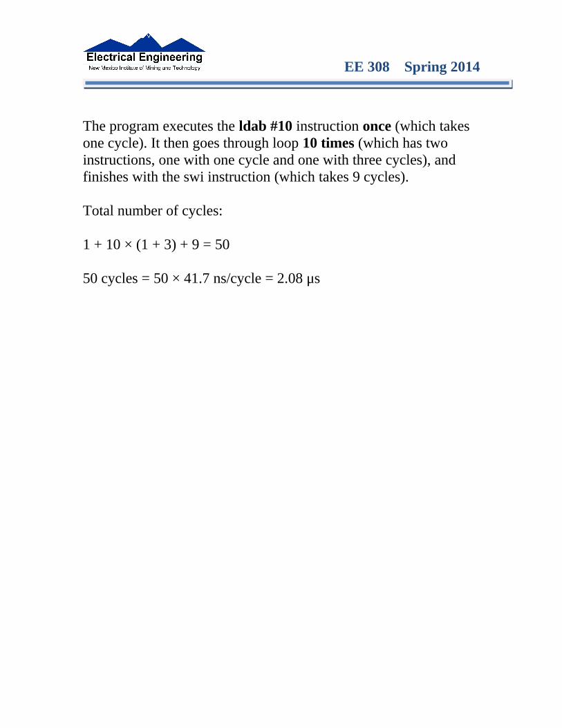
2000 org $2000 ; Inst Mode Cycles2000 C6 0A ldab #10 ; LDAB (IMM) 12002 87 loop: clra ; CLRA (INH) 12003 04 31 FC dbne b,loop ; DBNE (REL) 32006 3F swi ; SWI 9
How many cycles does it take?How long does it take to execute?
EE 308 Spring 2014
The program executes the ldab #10 instruction once (which takes one cycle). It then goes through loop 10 times (which has two instructions, one with one cycle and one with three cycles), and finishes with the swi instruction (which takes 9 cycles).
Total number of cycles:
1 + 10 × (1 + 3) + 9 = 50
50 cycles = 50 × 41.7 ns/cycle = 2.08 μs
EE 308 Spring 2014
EE 308 Spring 2014

EE 308 Spring 2014
EE 308 Spring 2014