ee 6351 electrical drives and control 3 0 0 100 …
TRANSCRIPT
EE 6351 ELECTRICAL DRIVES AND CONTROL 3 0 0 100
OBJECTIVE
1.
To understand the basic concepts of different types of electrical machines and their Performance. To study the different methods of starting D.C motors and induction motors. To study the conventional and solid-state drives.
8 INTRODUCTION
Basic Elements – Types of Electric Drives – factors influencing the choice of electrical drives – heating and cooling curves – Loading conditions and classes of duty – Selection of power rating for drive motors with regard to thermal overloading and Load variation factors
4. CONVENTIONAL AND SOLID STATE SPEED CONTROL OF D.C. DRIVES
Types of D.C Motor starters – Typical control circuits for shunt and series motors – Three phase squirrel cage and slip ring induction motors.
10
Speed control of three phase induction motor – Voltage control, voltage / frequency control, slip power recovery scheme – Using inverters and AC voltage regulators – applications.
TOTAL : 45
McGraw-
TEXT BOOKS
1.
2.
REFERENCES
1.PILLAI.S.K “A first course on Electric drives”, Wiley Eastern Limited, 1998 2.M.D.SINGH, K.B.KHANCHANDANI, “Power Electronics”, Tata McGraw-Hill, 1998 H.Partab, “Art and Science and Utilisation of electrical energy”, Dhanpat Rai and Sons, 1994
VEDAM SUBRAHMANIAM, “Electric Drives (concepts and applications)”, Tata Hill, 2001 NAGRATH.I.J. & KOTHARI.D.P, “Electrical Machines”, Tata McGraw-Hill, 1998
5. CONVENTIONAL AND SOLID STATE SPEED CONTROL OF A.C. DRIVES
Speed control of DC series and shunt motors – Armature and field control, Ward-Leonard control system - Using controlled rectifiers and DC choppers –applications.
10
3. STARTING METHODS
Mechanical characteristics – Speed-Torque characteristics of various types of load and drive motors – Braking of Electrical motors – DC motors: Shunt, series and compound - single phase and three phase induction motors.
8
2. DRIVE MOTOR CHARACTERISTICS 9
www.Vidyarthiplus.com

UNIT-I
INTRODUCTION TO ELECTRICAL DRIVES
Drives are employed for systems that require motion control – e.g. transportation
system, fans, robots, pumps, machine tools, etc. Prime movers are required in drive systems to
provide the sources: diesel engines, petrol engines, hydraulic motors, electric motors etc.
movement or motion and energy that is used to provide the motion can come from various
Drives that use electric motors as the prime movers are known as electrical drives.
There are several advantages of electrical drives:
a. Flexible control characteristic – This is particularly true when power electronic
Converters are employed where the dynamic and steady state characteristics of the motor
can be controlled by controlling the applied voltage or current.
b. Available in wide range of speed, torque and power
c. High efficiency, lower noise, low maintenance requirements and cleaner operation
d. Electric energy is easy to be transported.
With the advancement of power electronics, microprocessors and digital electronics,
typical Electric drive systems nowadays are becoming more compact, efficient, cheaper and
versatile this is shown in Figure 2. The voltage and current applied to the motor can be
changed at will by employing power electronic converters. AC motor is no longer limited to
application where only AC source is available, however, it can also be used when the power
source available is DC or vice versa
A typical conventional electric drive system for variable speed application employing
multi-machine system is shown in Figure 1. The system is obviously bulky, expensive,
inflexible and require regular maintenance. In the past, induction and synchronous machines
were used for constant speed applications – this was mainly because of the unavailability of
variable frequency supply.
www.Vidyarthiplus.comwww.Vidyarthiplus.com

COM PONENTS OF ELECTRICAL DRIVES
The main components of a modern electrical drive are the motors, power processor, control
unit and electrical source. These are briefly discussed below
a) Motors : Motors obtain power from electrical sources. They convert energy from
electrical to mechanical - therefore can be regarded as energy converters. In braking mode, the
flow of power is reversed. Depending upon the type of power converters
Electric drives is multi-disciplinary field. Various research areas can be sub-divided from
electric drives as shown in Figure 3.
www.Vidyarthiplus.comwww.Vidyarthiplus.com

used, it is also possible for the power to be fed back to the sources rather than dissipated as
heat
There are several types of motors used in electric drives – choice of type used depends on
applications, cost, environmental factors and also the type of sources available.. Broadly, they
can be classified as either DC or AC motors they can be classified as either DC or AC motors:
DC motors (wound or permanent magnet)
AC motors
Induction motors – squirrel cage, wound rotor
Synchronous motors – wound field, permanent magnet
Brushless DC motor – require power electronic converters
Stepper motors – require power electronic converters
Synchronous reluctance motors or switched reluctance motor – require power electronic
converters
b) Power processor or power modulator
Since the electrical sources are normally uncontrollable, it is therefore necessary to be able to
control the flow of power to the motor – this is achieved using power processor or power modulator.
With controllable sources, the motor can be reversed, brake or can be operated with variable speed.
Conventional methods used, for example, variable impedance or relays, to shape the voltage or
current that is supplied to the motor – these methods however are inflexible and inefficient. Modern
electric drives normally used power electronic converters to shape the desired voltage or current
supplied to the motor. In other words, the characteristic of the motors can be changed at will. Power
electronic converters have several advantages over classical methods of power conversion, such as
1) More efficient – since ideally no losses occur in power electronic converters
2) Flexible – voltage and current can be shaped by simply controlling switching functions of the
power converter.
3) Compact – smaller, compact and higher ratings solid–state power electronic devices are
continuously being developed – the prices are getting cheaper. Converters are used to convert and
possibly regulate (i.e. using closed-loop control) the available sources to suit the load i.e. motors.
These converters are efficient because the switches operate in either cut-off or saturation modes.
Several conversions are possible.
www.Vidyarthiplus.comwww.Vidyarthiplus.com

b) Control Unit
The complexity of the control unit depends on the desired drive performance and the type of
motors used. A controller can be as simple as few op-amps and/or a few digital ICs, or it can
be as complex as the combinations of several ASICs and digital signal processors (DSPs). The
types of the main controllers can be
• analog - which is noisy, inflexible. However analog circuit ideally has infinite bandwidth.
• digital – immune to noise, configurable. The bandwidth is obviously smaller than the analog
controllers – depends on sampling frequency.
www.Vidyarthiplus.comwww.Vidyarthiplus.com
• DSP/microprocessor – flexible, lower bandwidth compared to above. DSPs perform faster
operation than microprocessors (multiplication in single cycle). With DSP/micro., complex
estimations and observers can be easily implemented.
d) Source
Electrical sources or power supplies provide the energy to the electrical motors. For
high efficiency operation, the power obtained from the electrical sources need to be regulated
using power electronic converters Power sources can be of AC or D C in nature and normally
are uncontrollable, i.e. their magnitudes or frequencies are fixed or depend on the sources of
energy such as solar or wind. AC source can be either three-phase or single-phase; 3-phase
sources are normally for high power applications
There can be several factors that affect the selection of different configuration of electrical
drive system such as
a) Torque and speed profile - determine the ratings of converters and the quadrant of operation
required.
b) Capital and running cost – Drive systems will vary in terms of start-up cost and running
cost, e.g. maintenance
c) Space and weight restrictions
d) Environment and location
3.1 Overall Considerations.
• Check the Current rating of the inverter and the motor. Power rating is only a rough guide
• Check that you have selected the correct operating voltage. 230V three phase input
MICROMASTERs will operate with single or three phase inputs; MIDIMASTERs will
operate with three phase only. Single phase input units can be more cost effective in some
cases, but note that 230V units will be damaged if operated at 400V.
• Check the speed range you require. Operation above normal supply frequency (50 or 60Hz)
is usually only possible at reduced power. Operation at low frequency and high torque can
cause the motor to overheat due to lack of cooling
• Synchronous motors require de-rating, typically by 2 -3 times. This is because the power
factor, and hence the current, can be very high at low frequency.
• Check overload performance. The inverter will limit current to 150 or 200 % of full current
very quickly - a standard, fixed speed motor will tolerate these overloads.
• Do you need to stop quickly? If so, consider using a braking resistor (braking unit on
MIDIMASTERs) to absorb the energy.
3. Selecting a Drive
Often drive selection is straight forward, as a motor is already installed and the speed
range requirement is not excessive. However, when a drive system is selected from first
principles, careful consideration may avoid problems in installation and operation, and may
also save significant cost.
www.Vidyarthiplus.comwww.Vidyarthiplus.com

• Do you need to operate with cables longer than 50m, or screened or armoured cables
longer than 25m? If so, it may be necessary to de-rate, or fit a choke to compensate for the
cable capacitance.
3.2 Motor limitations
For more information concerning calculation of Power requirements, Torque, and
Moment of Inertia, see later. The motor speed is determined mainly by the applied frequency.
The motor slows down a little as the load increases and the slip increases. If the load is too
great the motor will exceed the maximum torque and stall or „pull out‟. Most motors and
inverters will operate at 150% load
The constructions of the machines are very complex; normally built from various types
of materials (heterogeneous) with complex geometrical shapes. To exactly predict the heat
flow and hence the temperature distribution is extremely difficult. Based on the assumptions
that the temperature limits of all parts does not exceed the temperature limits under certain
operating conditions, the motors can therefore adequately modeled as homogeneous bodies.
Obviously, this assumption cannot determine the specific internal thermal conditions for the
motors.
Friction and wind age losses:
Mainly due to ball bearings, brushes, ventilation losses
Core losses:
Mainly due to eddy current and hysteresis losses
Conductor losses:
Exist in the windings, cables, brushes, slip rings, commutator, etc. .
The losses in the machines contribute to the temperature increase in the machine. The
various parts of the machine use different type of insulation materials which have different
temperature limits. Particularly important is the insulation used for the windings which give
rise to the different classes of machines. Allowable power losses are higher for materials
which can withstand higher temperature which translates to higher costs. Three main cause of
power losses are:
Thermal considerations
www.Vidyarthiplus.comwww.Vidyarthiplus.com

Where is the thermal time constant? With power input p1
from 0 to ph at t=0, the solution for is
where is the coefficient of heat transfer. If we let equation
(12) can be written as
The heat dissipated by convection is given by
and a step change in the
At steady state,\
During cooling, i.e. when heat is removed at t=0, the temperature of the body decays to
the ambient temperature.
Let us assume that a homogeneous body shown in Figure 12 represents a motor which
has a thermal capacity C. The input power, which is the losses incurred in the motor, is
represented by p1 whereas the output power, which is the power released as heat by
convection, is represented by p2. The output power due to radiation is assumed negligible
because of the low operating temperature and back radiation. Under a steady state condition,
the input power equals the output power; this is when the steady state temperature is reached.
The equation describing the power balance is given by
www.Vidyarthiplus.comwww.Vidyarthiplus.com

Ratings of converters and motors
In order to accelerate to a given reference value, the motor torque has to be larger than the
load torque. According to (1), the difference between T1 and Te determines how fast the
angular acceleration is. For example, the speed and torque responses for a closed-loop speed
control DC drive with two different torque limit setting (10 Nm and 15 Nm) is shown in
Figure 7. The higher the torque during the speed transient, the faster is the speed gets to its
reference
If the thermal time constant is large, a temporary overload is therefore possible without
exceeding the temperature limits. Three typical modes of operation are:
- Continuous duty
- Short time intermittent duty
- Periodic intermittent duty
www.Vidyarthiplus.comwww.Vidyarthiplus.com

In most cases, the torque during this transient condition can be up to 3 times the rated
torque of the motor and for servo motor, it can be as high as 8 to 10 times the rated value. This
momentary high torque is possible due to the large thermal capacity of the motor with suitable
insulators used for the winding. The converter, which conducts the motor current, must be able
to sustain this condition. However since the thermal capacity of the converter is small, the
current cannot be higher than its rated value. Consequently, the current rating of the converter
is normally set to equal the maximum allowable motor current and this can be as high as the 3
times the motor rated current. The maximum allowable torque during transient of a drive
system is determined by the current rating of the converter used whereas the continuous torque
limit depends on the current rating of the motor. The operating area of a 4-quadrant motor
drive is shown in Figure 8. The converter is normally protected from the over-current
condition by the current limiter mechanism within the converter system, which means that
sustained overloads on the motor has to be protected by an additional thermal protection the
torque is limited by the maximum mechanism. Above the base speed, allowable power, which
depends on whether the transient or continuous torque limit is considered? The speed limit
basically depends on the mechanical limitation of the motor.
www.Vidyarthiplus.comwww.Vidyarthiplus.com

Fig. Limits for torque, speed and power for drive system
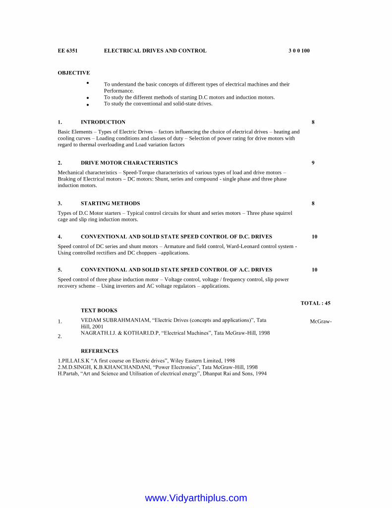
The motor will operate at the steady-state speed (point where T1 = Te) provided that
the speed is of stable equilibrium. The stable equilibrium speed is investigated using steady-
state torque- speed characteristics of the load and motor. A disturbance in any part of the drive
will result in a speed to depart from the steady state speed. However, if the steady-state speed
is of stable equilibrium, the speed will return to the stable equilibrium speed. On the other
hand, if the speed is not of the stable equilibrium, the disturbance will results in the speed to
drift away from the equilibrium speed. It can be shown that the condition for stable
equilibrium is:
Steady-state stability
www.Vidyarthiplus.comwww.Vidyarthiplus.com
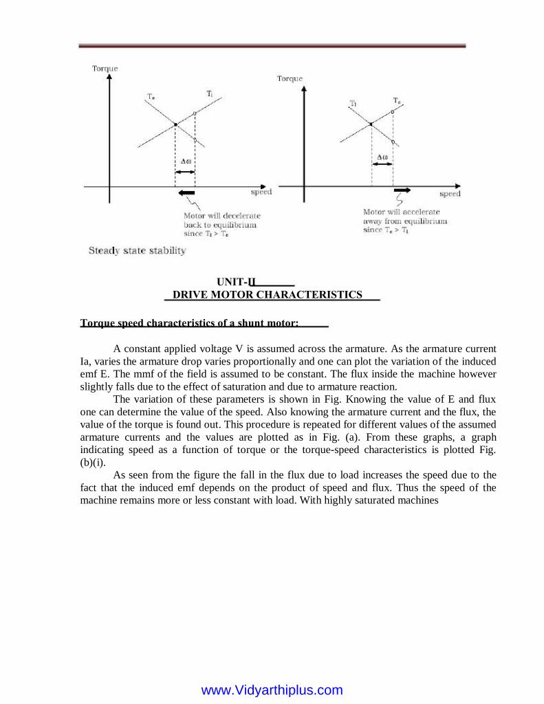
A constant applied voltage V is assumed across the armature. As the armature current
Ia, varies the armature drop varies proportionally and one can plot the variation of the induced
emf E. The mmf of the field is assumed to be constant. The flux inside the machine however
slightly falls due to the effect of saturation and due to armature reaction.
The variation of these parameters is shown in Fig. Knowing the value of E and flux
one can determine the value of the speed. Also knowing the armature current and the flux, the
value of the torque is found out. This procedure is repeated for different values of the assumed
armature currents and the values are plotted as in Fig. (a). From these graphs, a graph
indicating speed as a function of torque or the torque-speed characteristics is plotted Fig.
(b)(i).
As seen from the figure the fall in the flux due to load increases the speed due to the
fact that the induced emf depends on the product of speed and flux. Thus the speed of the
machine remains more or less constant with load. With highly saturated machines
Torque speed characteristics of a shunt motor:
UNIT-II
DRIVE MOTOR CHARACTERISTICS
www.Vidyarthiplus.comwww.Vidyarthiplus.com
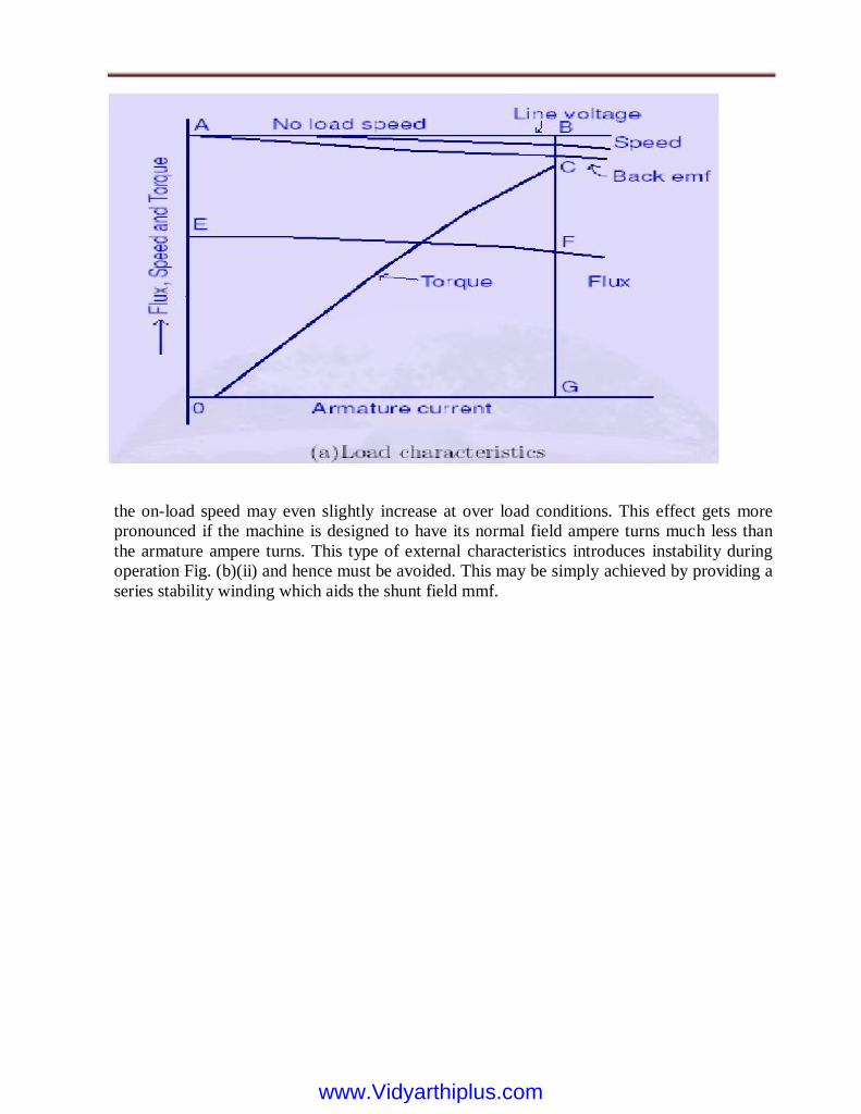
the on-load speed may even slightly increase at over load conditions. This effect gets more
pronounced if the machine is designed to have its normal field ampere turns much less than
the armature ampere turns. This type of external characteristics introduces instability during
operation Fig. (b)(ii) and hence must be avoided. This may be simply achieved by providing a
series stability winding which aids the shunt field mmf.
www.Vidyarthiplus.comwww.Vidyarthiplus.com

Load characteristics of a series motor
Following the procedure described earlier under shunt motor, the torque speed
Characteristics of a series motor can also be determined. The armature current also happens to
be the excitation current of the series field and hence the flux variation resembles the
magnetization curve of the machine. At large value of the armature currents the useful flux
would be less than the no-load magnetization curve for the machine. Similarly for small values
of the load currents the torque varies as a square of the armature currents as the flux is
proportional to armature current in this region. As the magnetic circuit becomes more and
more saturated the torque becomes proportional to Ia as flux variation becomes small. Fig. (a)
shows the variation of E1, flux, torque and speed following the above procedure from which
the torque-speed characteristics of the series motor for a given applied voltage V can be
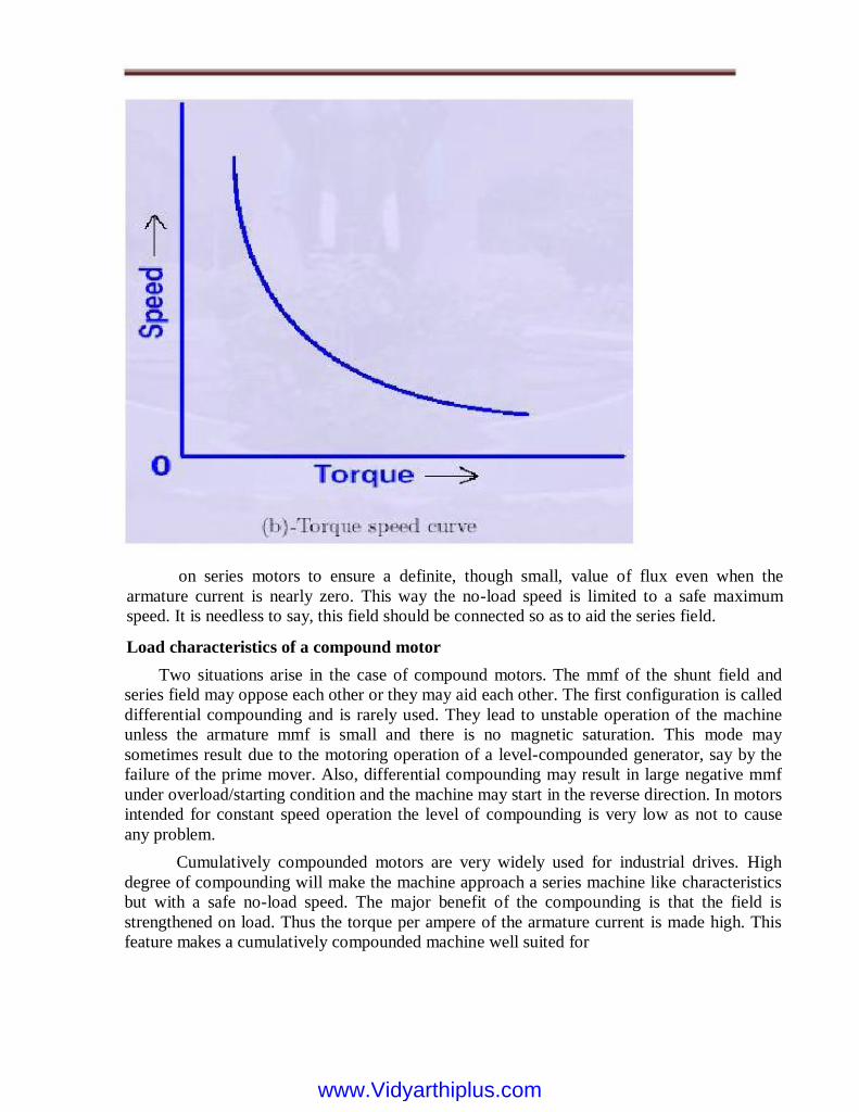
plotted as shown in Fig.(b) The initial portion of this torque-speed curve is seen to be a
rectangular hyperbola and the final portion is nearly a straight line. The speed under light load
conditions is many times more than the rated speed of the motor. Such high speeds are unsafe,
as the centrifugal forces acting on the armature and
www.Vidyarthiplus.comwww.Vidyarthiplus.com
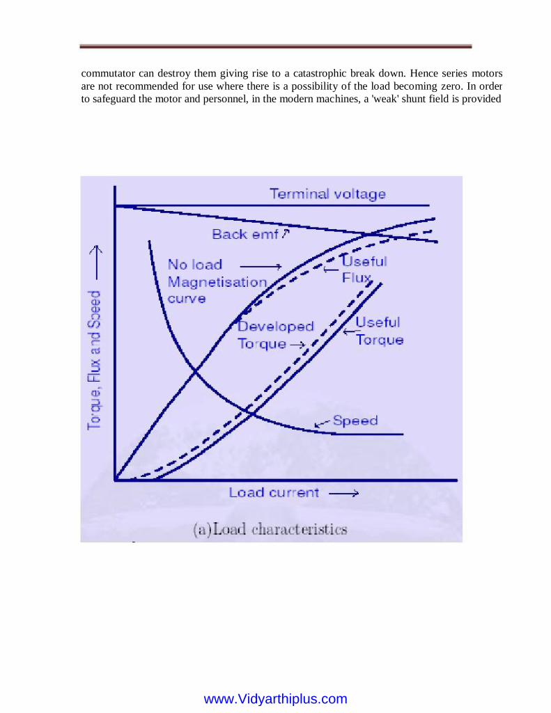
commutator can destroy them giving rise to a catastrophic break down. Hence series motors
are not recommended for use where there is a possibility of the load becoming zero. In order
to safeguard the motor and personnel, in the modern machines, a 'weak' shunt field is provided
www.Vidyarthiplus.comwww.Vidyarthiplus.com
Two situations arise in the case of compound motors. The mmf of the shunt field and
series field may oppose each other or they may aid each other. The first configuration is called
differential compounding and is rarely used. They lead to unstable operation of the machine
unless the armature mmf is small and there is no magnetic saturation. This mode may
sometimes result due to the motoring operation of a level-compounded generator, say by the
failure of the prime mover. Also, differential compounding may result in large negative mmf
under overload/starting condition and the machine may start in the reverse direction. In motors
intended for constant speed operation the level of compounding is very low as not to cause
any problem.
Cumulatively compounded motors are very widely used for industrial drives. High
degree of compounding will make the machine approach a series machine like characteristics
but with a safe no-load speed. The major benefit of the compounding is that the field is
strengthened on load. Thus the torque per ampere of the armature current is made high. This
feature makes a cumulatively compounded machine well suited for
Load characteristics of a compound motor
on series motors to ensure a definite, though small, value of flux even when the
armature current is nearly zero. This way the no-load speed is limited to a safe maximum
speed. It is needless to say, this field should be connected so as to aid the series field.
www.Vidyarthiplus.comwww.Vidyarthiplus.com

intermittent peak loads. Due to the large speed variation between light load and peak load
conditions, a y wheel can be used with such motors with advantage. Due to the reasons
provided under shunt and series motors for the provision of an additional series/shunt
winding, it can be seen that all modern machines are compound machines. The difference
between them is only in the level of compounding.
Braking of D.C. Motors
When a motor is switched off it `coasts' to rest under the action of frictional
forces. Braking is employed when rapid stopping is required. In many cases
mechanical braking is adopted. The electric braking may be done for various reasons
such as those mentioned below:
1. To augment the brake power of the mechanical brakes.
2. To save the life of the mechanical brakes.
3. To regenerate the electrical power and improve the energy efficiency.
4. In the case of emergencies to step the machine instantly.
5. To improve the throughput in many production processes by reducing the stopping time.
In many cases electric braking makes more brake power available to the braking process
where mechanical brakes are applied. This reduces the wear and tear of the mechanical brakes
and reduces the frequency of the replacement of these parts. By recovering the mechanical
energy stored in the rotating parts and pumping it into the supply lines the overall energy
efficiency is improved. This is called regeneration. Where the safety of the personnel or the
equipment is at stake the machine may be required to stop instantly.
Extremely large brake power is needed under those conditions. Electric braking can help
in these situations also. In processes where frequent starting and stopping is involved the
process time requirement can be reduced if braking time is reduced. The reduction of the
1. Dynamic
2. Regenerative
3. Reverse voltage braking or plugging
These are now explained briefly with reference to shunt, series and compound motors.
Dynamic braking
Shunt machine
In dynamic braking the motor is disconnected from the supply and connected to a
dynamic braking resistance RDB. In and Fig. 49 this is done by changing the switch from
position 1 to 2. The supply to the field should not be removed. Due to the rotation of the
armature during motoring mode and due to the inertia, the armature continues to rotate. An
emf is induced due to the presence of the field and the rotation. This voltage drives a
www.Vidyarthiplus.comwww.Vidyarthiplus.com
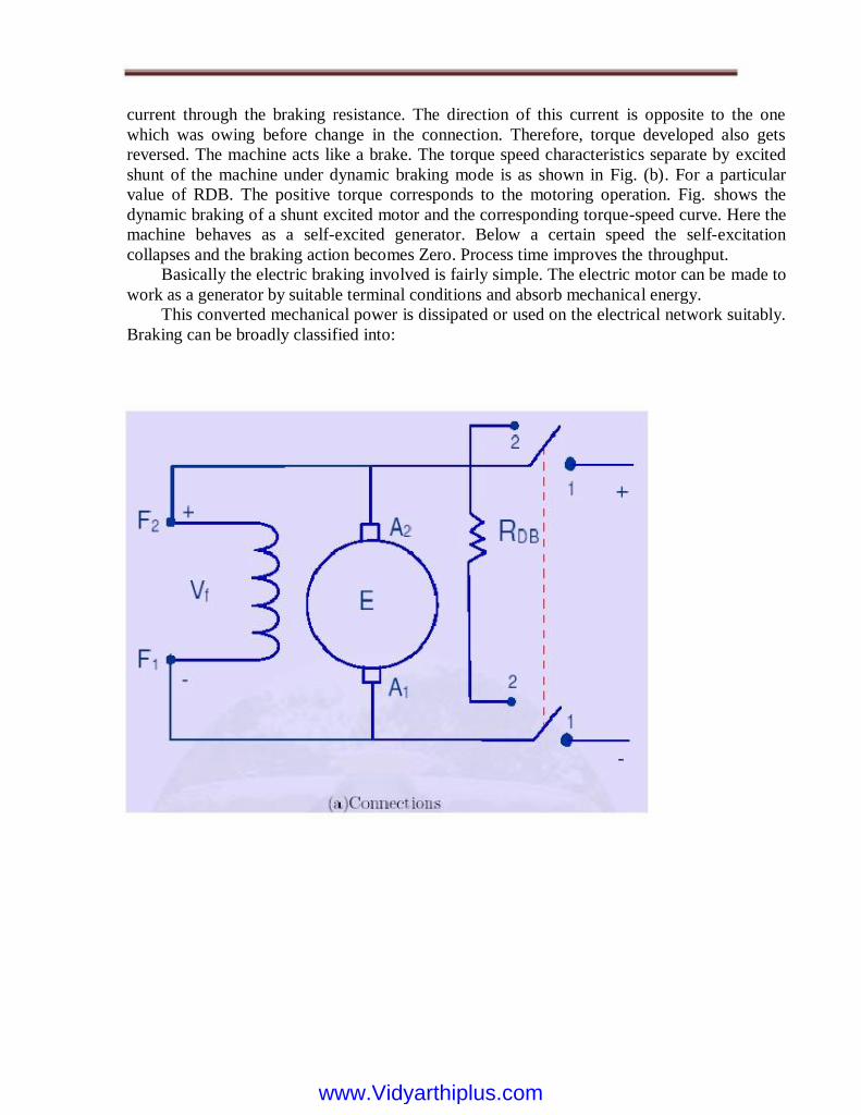
current through the braking resistance. The direction of this current is opposite to the one
which was owing before change in the connection. Therefore, torque developed also gets
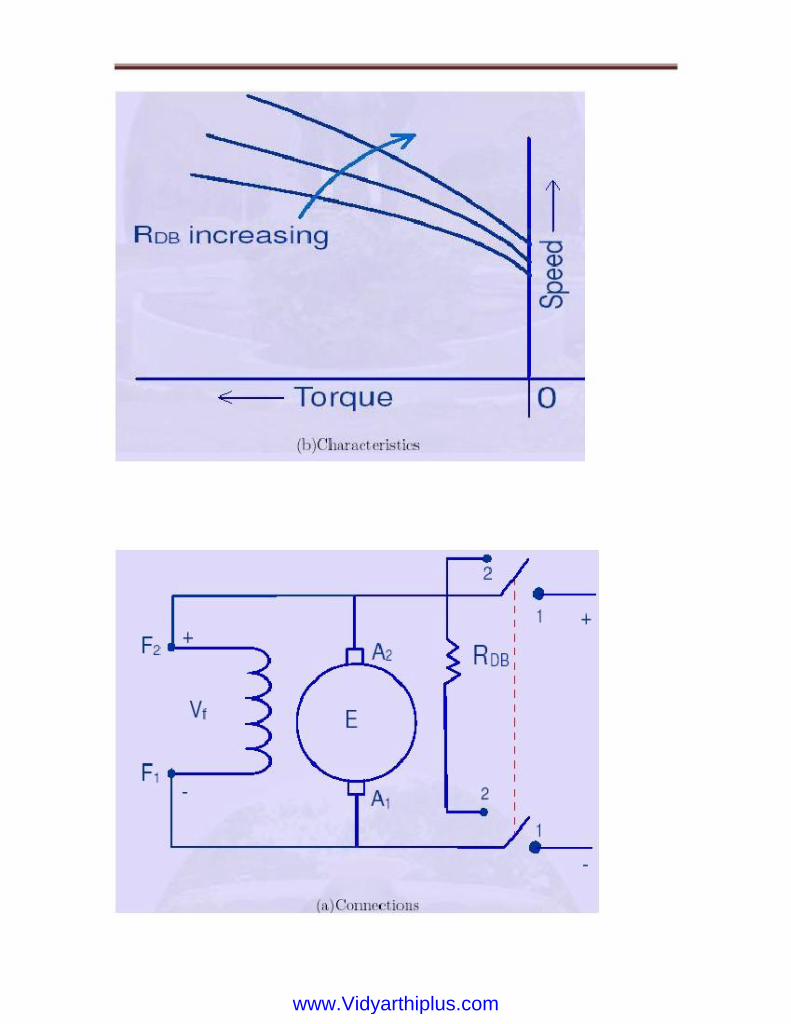
reversed. The machine acts like a brake. The torque speed characteristics separate by excited
shunt of the machine under dynamic braking mode is as shown in Fig. (b). For a particular
value of RDB. The positive torque corresponds to the motoring operation. Fig. shows the
dynamic braking of a shunt excited motor and the corresponding torque-speed curve. Here the
machine behaves as a self-excited generator. Below a certain speed the self-excitation
collapses and the braking action becomes Zero. Process time improves the throughput.
Basically the electric braking involved is fairly simple. The electric motor can be made to
work as a generator by suitable terminal conditions and absorb mechanical energy.
This converted mechanical power is dissipated or used on the electrical network suitably.
Braking can be broadly classified into:
www.Vidyarthiplus.comwww.Vidyarthiplus.com
www.Vidyarthiplus.comwww.Vidyarthiplus.com

Figure: Dynamic braking of shunt excited shunt machine
Compound generators
In the case of compound machine, the situation is like in a shunt machine. A separately
excited shunt field and the armature connected across the braking resistance are used.
A cumulatively connected motor becomes differentially compounded generator and the
braking torque generated comes down. It is therefore necessary to reverse the series field if
large braking torques are desired.
In the case of a series machine the excitation current becomes zero as soon as the
armature is disconnected from the mains and hence the induced emf also vanishes. In order to
achieve dynamic braking the series field must be isolated and connected to a low voltage high
current source to provide the field. Rather, the motor is made to work like a separately excited
machine. When several machines are available at any spot, as in railway locomotives,
dynamic braking is feasible. Series connection of all the series fields with parallel connection
of all the armatures connected across a single dynamic braking resistor is used in that case.
Series machine
www.Vidyarthiplus.comwww.Vidyarthiplus.com
Regenerative braking
In regenerative braking as the name suggests the energy recovered from the rotating
masses is fed back into the d.c. power source. Thus this type of braking improves the energy
efficiency of the machine. The armature current can be made to reverse for a constant voltage
operation by increase in speed/excitation only. Increase in speed does not result in braking and
the increase in excitation is feasible only over a small range, which may be of the order of 10
to 15%. Hence the best method for obtaining the regenerative braking is to operate, the
machine on a variable voltage supply. As the voltage is continuously pulled below the value
of the induced emf the speed steadily comes down. The field current is held constant by means
of separate excitation. The variable d.c. supply voltage can be obtained by Ward-Leonard
arrangement, shown schematically in Fig. .
Braking torque can be obtained right up to zero speed. In modern times static Ward-
Leonard scheme is used for getting the variable d.c. voltage. This has many advantages over
its rotating machine counter part. Static set is compact, has higher efficiency, and requires
lesser space and silent in operation; however it suffers from drawbacks like large ripple at low
voltage levels, unidirectional power flow and low over load capacity. Bidirectional power
flow capacity is a must if regenerative braking is required. Series motors cannot be
regenerative braked as the characteristics do not extend to the second quadrant.
Plugging
The third method for braking is by plugging. Fig. shows the method of connection for the
plugging of a shunt motor. Initially the machine is connected to the supply with the switch S
in position number 1. If now the switch is moved to position 2, then a reverse voltage is
applied across the armature. The induced armature voltage E and supply voltage V aid each
other and a large reverse current flows through the armature. This produces a large negative
torque or braking torque. Hence plugging is also termed as reverse voltage braking. The
machine instantly comes to rest. If the motor is not switched off at this instant the direction of
rotation reverses and the motor starts rotating the reverse direction. This type of braking
therefore has two modes viz. 1) plug to reverse and 2) plug to stop. If we need the plugging
only for bringing the speed to zero, then we have to open the switch S at zero speed. If nothing
is done it is plug to reverse mode. Plugging is a convenient mode for quick reversal of
direction of rotation in reversible drives. Just as in starting, during
www.Vidyarthiplus.comwww.Vidyarthiplus.com

www.Vidyarthiplus.comwww.Vidyarthiplus.com

Figure: Plugging or reverse voltage braking of a shunt motor
www.Vidyarthiplus.comwww.Vidyarthiplus.com
Plugging also it is necessary to limit the current and thus the torque, to reduce the
stress on the mechanical system and the commutator. This is done by adding additional
resistance in series with the armature during plugging.
Series motors
In the case of series motors plugging cannot be employed as the field current too gets
reversed when reverse voltage is applied across the machine. This keeps the direction of the
torque produced unchanged. This fact is used with advantage, in operating a D.C. series motor
on D.C. or A.C. supply. Series motors thus qualify to be called as `Universal motors'.
From the equivalent circuit, many aspects of the steady state behavior of the machine can
be deduced. We will begin by looking at the speed-torque characteristic of the machine. We
will consider the approximate equivalent circuit of the machine. We have reasoned earlier that
the power consumed by the 'rotor-portion' of the equivalent circuit is the power transferred
across the air-gap. Out of that quantity the amount dissipated in R0 r is the rotor copper loss
and the quantity consumed by R0r(1 + s)=s is the mechanical power developed. Neglecting
mechanical losses, this is the power available at the shaft. The torque available can be
obtained by dividing this number by the shaft speed.
The complete torque-speed characteristic of Induction motor
In order to estimate the speed torque characteristic let us suppose that a sinusoidal voltage
is impressed on the machine. Recalling that the equivalent circuit is the per-phase
representation of the machine, the current drawn by the circuit is given by
Deducing the machine performance (Single phase Induction motor)
Plugging of compound motors proceeds on similar lines as the shunt motors. However
some precautions have to be observed due to the presence of series field winding. A
cumulatively compounded motor becomes differentially compounded on plugging. The MMF
due to the series field can 'over power' the shunt field forcing the flux to low values or even
reverse the net field. This decreases the braking torque, and increases the duration of the large
braking current. To avoid this it may be advisable to deactivate the series field at the time of
braking by short-circuiting the same. In such cases the braking proceeds just as in a shunt
motor. If plugging is done to operate the motor in the negative direction of rotation as well,
then the series field has to be reversed and connected for getting the proper mmf. Unlike
dynamic braking and regenerative braking where the motor is made to work as a generator
during braking period, plugging makes the motor work on reverse motoring mode.
Compound motors
www.Vidyarthiplus.comwww.Vidyarthiplus.com

Where Vs is the phase voltage phases and Is is the current phases. The magnetizing current is
neglected. Since this current is owing through, the air-gap power is given by
The mechanical power output was shown to be (1_s) Pg (power dissipated in R0r=s). The
torque is obtained by dividing this by the shaft speed .Thus we have,
The torque may be plotted as a function of `s' and is called the torque-slip (or torque-
speed, since slip indicates speed) characteristic a very important characteristic of the induction
machine. Equation 16 is valid for a two-pole (one pole pair) machine. In general, this
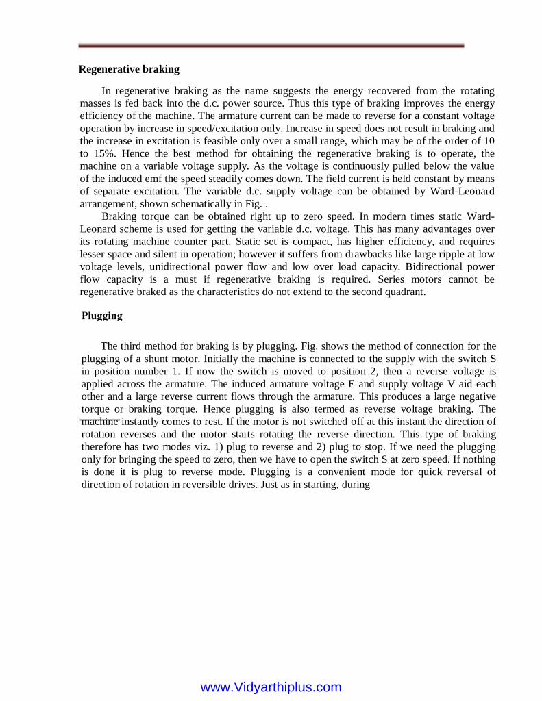
expression should be multiplied by p, the number of pole-pairs. A typical torque-speed
characteristic is shown in fig. 22. This plot corresponds to a 3 kW, 4 pole and 60 Hz machine.
The rated operating speed is 1780 rpm.
We must note that the approximate equivalent circuit was used in deriving this
relation. Readers with access to MATLAB or suitable equivalents (octave, scalar available
free under GNU at the time of this writing) may find out the difference caused by using the
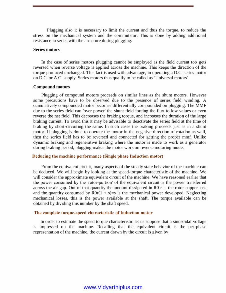
`exact' equivalent circuit by using the script found here. A comparison between the two is
found in the plot of fig. The plots correspond to a 3 kW, 4 poles, 50 machines, with a rated
speed of 1440 rpm. It can be seen that the approximate equivalent circuit is a good
approximation in the operating speed range of the machine. Comparing the two figures. We
can see that the slope and shape of the characteristics are dependent intimately on the machine
parameters.
Further, this curve is obtained by varying slip with the applied voltage being held
constant. Coupled with the fact that this is an equivalent circuit valid under steady state, it
implies that if this characteristic is to be measured experimentally, we need to look at the
torque for a given speed after all transients have died down. One cannot, for example, try
Where! S is the synchronous speed in radians per second and s is the slip. Further, this is the
torque produced per phase. Hence the overall torque is given by
www.Vidyarthiplus.comwww.Vidyarthiplus.com
Torque, Nm to obtain this curve by directly starting the motor with full voltage applied
to the terminals and measuring the torque and speed dynamically as it runs up to steady speed.
Another point to note is that the equivalent circuit and the values of torque predicted is
valid when the applied voltage waveform is sinusoidal. With non-sinusoidal voltage
waveforms, the procedure is not as straight forward.
With respect to the direction of rotation of the air-gap flux, the rotor maybe driven to
higher speeds by a prime mover or may also be rotated in the reverse direction. The torque-
speed relation for the machine under the entire speed range is called the complete speed-
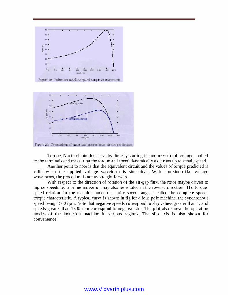
torque characteristic. A typical curve is shown in fig for a four-pole machine, the synchronous
speed being 1500 rpm. Note that negative speeds correspond to slip values greater than 1, and
speeds greater than 1500 rpm correspond to negative slip. The plot also shows the operating
modes of the induction machine in various regions. The slip axis is also shown for
convenience.
www.Vidyarthiplus.comwww.Vidyarthiplus.com
Substituting ^s into the expression for torque gives us the value of the stalling torque ^ T
the negative sign being valid for negative slip.
The expression shows that ^ Te is the independent of R0 r, while ^s is directly
proportional to R0 r. This fact can be made use of conveniently to alter ^s. If it is possible to
change R0 r, then we can get a whole series of torque-speed characteristics, the maximum
torque remaining constant all the while. But this is a subject to be discussed later.
The value of the stalling torque may be obtained by differentiating the expression for
torque with respect to zero and setting it to zero to find the value of ^s. Using this method,
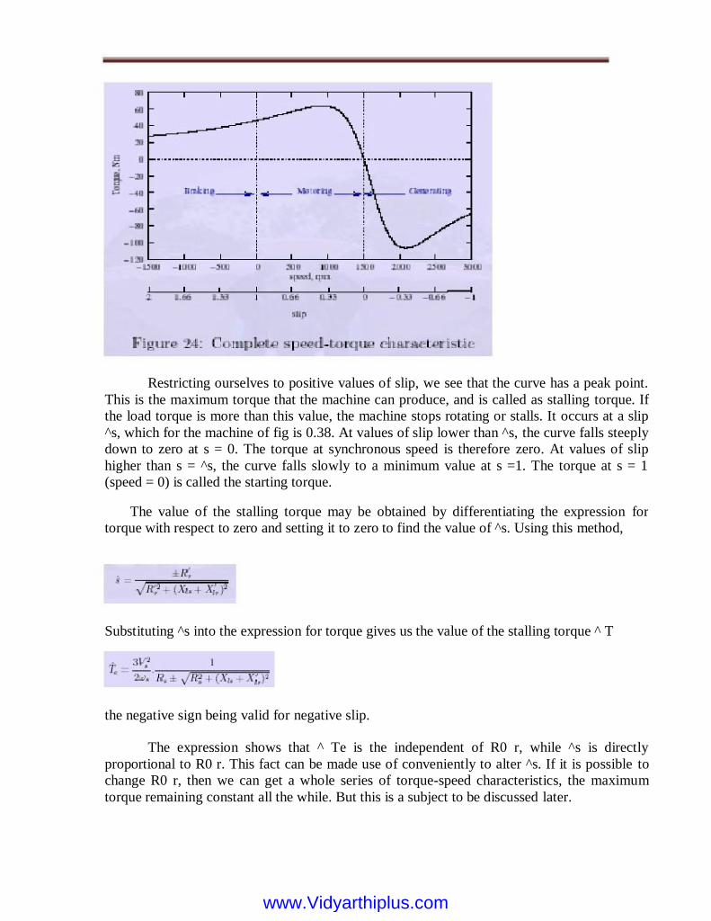
Restricting ourselves to positive values of slip, we see that the curve has a peak point.
This is the maximum torque that the machine can produce, and is called as stalling torque. If
the load torque is more than this value, the machine stops rotating or stalls. It occurs at a slip
^s, which for the machine of fig is 0.38. At values of slip lower than ^s, the curve falls steeply
down to zero at s = 0. The torque at synchronous speed is therefore zero. At values of slip
higher than s = ^s, the curve falls slowly to a minimum value at s =1. The torque at s = 1
(speed = 0) is called the starting torque.
www.Vidyarthiplus.comwww.Vidyarthiplus.com

We may note that if R is chosen equal to becomes unity, which p means that the maximum
torque occurs at starting. Thus changing of R r, wherever possible can serve as a means to
control the starting torque.
While considering the negative slip range, (generator mode) we note that the maximum
torque is higher than in the positive slip region (motoring mode).
Operating Point
Consider a speed torque characteristic shown in fig. For an induction machine, having the
load characteristic also superimposed on it. The load is a constant torque load i.e., the torque
required for operation is fixed irrespective of speed. The system consisting of the motor and
load will operate at a point where the two characteristics meet. From the above plot, we note
that there are two such points. We therefore need to find out which of these is the actual
operating point.
To answer this we must note that, in practice, the characteristics are never fixed; they
change slightly with time. It would be appropriate to consider a small band around the curve
drawn where the actual points of the characteristic will lie. This being the case let us considers
that the system is operating at point 1, and the load torque demand increases slightly. This is
shown in fig, where the change is exaggerated for clarity. This would shift the point of
operation to a point 10 at which the slip would be less and the developed torque higher.
The difference in torque-developed 4Te, being positive will accelerate the machine. Any
overshoot in speed as it approaches the point 10 will cause it to further accelerate since the
developed torque is increasing. Similar arguments may be used to show that if for some reason
the developed torque becomes smaller the speed would drop and the effect is cumulative.
Therefore we may conclude that 1 is not a stable operating point.
Let us consider the point 2. If this point shifts to 20, the slip is now higher (speed is
lower) and the positive difference in torque will accelerate the machine. This behavior will
tend to bring the operating point towards 2 once again. In other words, disturbances at point 2
will not cause a runaway effect. Similar arguments may be given for the case where the load
characteristic shifts down. Therefore we conclude that point 2 is a stable operating point.
www.Vidyarthiplus.comwww.Vidyarthiplus.com
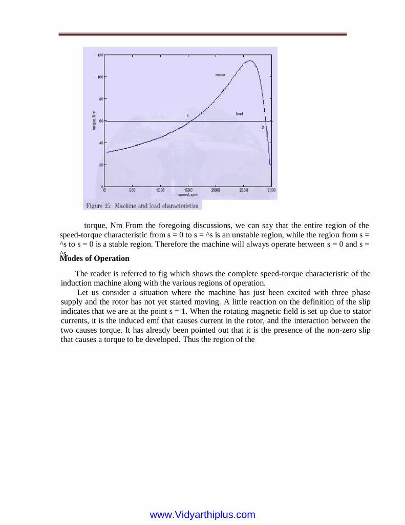
The reader is referred to fig which shows the complete speed-torque characteristic of the
induction machine along with the various regions of operation.
Let us consider a situation where the machine has just been excited with three phase
supply and the rotor has not yet started moving. A little reaction on the definition of the slip
indicates that we are at the point s = 1. When the rotating magnetic field is set up due to stator
currents, it is the induced emf that causes current in the rotor, and the interaction between the
two causes torque. It has already been pointed out that it is the presence of the non-zero slip
that causes a torque to be developed. Thus the region of the
Modes of Operation
torque, Nm From the foregoing discussions, we can say that the entire region of the
speed-torque characteristic from s = 0 to s = ^s is an unstable region, while the region from s =
^s to s = 0 is a stable region. Therefore the machine will always operate between s = 0 and s =
^s.
www.Vidyarthiplus.comwww.Vidyarthiplus.com

Figure: Stability of operating point
s = 0 and s = 1 is the region where the machine produces torque to rotate a passive load
and hence is called the motoring region. Note further that the direction of rotation of the rotor
is the same as that of the air gap flux.
Suppose when the rotor is rotating, we change the phase sequence of excitation to the
machine. This would cause the rotating stator field to reverse its direction the rotating stator
mmf and the rotor are now moving in opposite directions. If we adopt the convention that
positive direction is the direction of the air gap flux, the rotor speed would then be a negative
quantity. The slip would be a number greater than unity. Further, the rotor as we know should
be "dragged along" by the stator field. Since the rotor is rotating in the opposite direction to
that of the field, it would now tend to slow down, and reach zero speed.
Therefore this region (s > 1) is called the braking region. (What would happen if the
supply is not cut-off when the speed reaches zero?) . There is yet another situation. Consider a
situation where the induction machine is operating from mains and is driving an active load (a
load capable of producing rotation by itself). A typical example is that of a windmill, where
the fan like blades of the windmill are connected to the shaft of the induction machine.
Rotation of the blades may be caused by the motoring action of the machine, or by wind
blowing. Further suppose that both acting independently cause rotation in the same direction.
Now when both grid and wind act, a strong wind may cause the rotor to rotate faster than the
mmf produced by the stator excitation. A little reaction shows that slip is then negative.
Further, the wind is rotating the rotor to a speed higher than what the electrical supply
alone would cause. In order to do this it has to contend with an opposing torque generated by
the machine preventing the speed build up. The torque generated is therefore negative. It is
this action of the wind against the torque of the machine that enables wind-energy generation.
The region of slip s > 1 is the generating mode of operation. Indeed this is at present the most
commonly used approach in wind-energy
curve between
www.Vidyarthiplus.comwww.Vidyarthiplus.com

generation. It may be noted from the torque expression of equation that torque is negative
for negative values of slip.
Braking of D.C. shunt motor: basic idea
It is often necessary in many applications to stop a running motor rather quickly. We
know that any moving or rotating object acquires kinetic energy. Therefore, how fast we can
bring the object to rest will depend essentially upon how quickly we can extract its kinetic
energy and make arrangement to dissipate that energy somewhere else. If you stop pedaling
your bicycle, it will eventually come to a stop eventually after moving quite some distance.
The initial kinetic energy stored, in this case dissipates as heat in the friction of the road.
However, to make the stopping faster, brake is applied with the help of rubber brake shoes on
the rim of the wheels.
Thus stored K.E now gets two ways of getting dissipated, one at the wheel-brake shoe
interface (where most of the energy is dissipated) and the other at the road-tier interface. This
is a good method no doubt, but regular maintenance of brake shoes due to wear and tear is
necessary.
If a motor is simply disconnected from supply it will eventually come to stop no doubt,
but will take longer time particularly for large motors having high rotational inertia. Because
here the stored energy has to dissipate mainly through bearing friction and wind friction. The
situation can be improved, by forcing the motor to operate as a generator during braking. The
idea can be understood remembering that in motor mode electromagnetic torque acts along the
direction of rotation while in generator the electromagnetic torque acts in the opposite
direction of rotation. Thus by forcing the machine to operate as generator during the braking
period, a torque opposite to the direction of rotation will be imposed on the shaft, thereby
helping the machine to come to stop quickly. During braking action, the initial K.E stored in
the rotor is either dissipated in an external resistance or fed back to the supply or both.
Rheostat braking
Consider a d.c shunt motor operating from a d.c supply with the switch S connected to
position 1 as shown in figure. S is a single pole double throw switch and can be connected
either to position 1 or to position 2. One end of an external resistance Rb is connected to
position 2 of the switch S as shown.
Let with S in position 1, motor runs at n rpm, drawing an armature current Ia and the back
emf is
www.Vidyarthiplus.comwww.Vidyarthiplus.com

opposition with the supply voltage. Also note Te and n have same clockwise direction.
since Ia has changed direction but has notAs time passes after switching, n decreases reducing
K.E and as a consequence both Eb and Ia decrease. In other words value of braking torque
will be highest at t = 0+, and it decreases progressively and becoming zero when the machine
finally come to a stop.
Plugging or dynamic braking
This method of braking can be understood by referring to figures 39.25 and 39.26. Here
S is a double pole double throw switch. For usual motoring mode, S is connected to positions
1 and 1'.
Now if S is suddenly thrown to position 2 at t = 0, the armature gets disconnected from
the supply and terminated by Rb with field coil remains energized from the supply. Since
speed of the rotor cannot change instantaneously, the back emf value Eb is still maintained
with same polarity prevailing at t = 0-. Thus at t = 0+, armature current will be Ia = Eb/(ra +
Rb) and with reversed direction compared to direction prevailing during motor mode at t = 0-.
Obviously for t > 0, the machine is operating as generator dissipating power to Rb and
now the electromagnetic torque Te must act in the opposite direction to that of n
www.Vidyarthiplus.comwww.Vidyarthiplus.com
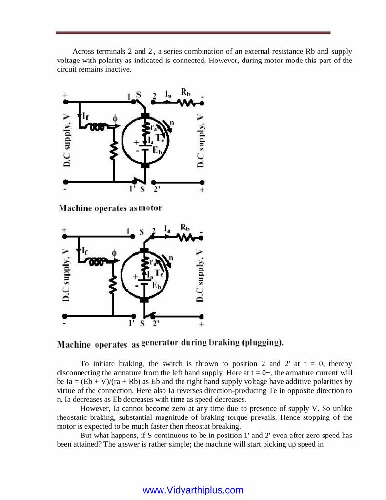
Across terminals 2 and 2', a series combination of an external resistance Rb and supply
voltage with polarity as indicated is connected. However, during motor mode this part of the
circuit remains inactive.
To initiate braking, the switch is thrown to position 2 and 2' at t = 0, thereby
disconnecting the armature from the left hand supply. Here at t = 0+, the armature current will
be Ia = (Eb + V)/(ra + Rb) as Eb and the right hand supply voltage have additive polarities by
virtue of the connection. Here also Ia reverses direction-producing Te in opposite direction to
n. Ia decreases as Eb decreases with time as speed decreases.
However, Ia cannot become zero at any time due to presence of supply V. So unlike
rheostatic braking, substantial magnitude of braking torque prevails. Hence stopping of the
motor is expected to be much faster then rheostat breaking.
But what happens, if S continuous to be in position 1' and 2' even after zero speed has
been attained? The answer is rather simple; the machine will start picking up speed in
www.Vidyarthiplus.comwww.Vidyarthiplus.com

the reverse direction operating as a motor. So care should be taken to disconnect the right
hand supply, the moment armature speed becomes zero.
Regenerative braking
A machine operating as motor may go into regenerative braking mode if its speed
becomes sufficiently high so as to make back emf greater than the supply voltage i.e., Eb > V.
Obviously under this condition the direction of Ia will reverse imposing torque which is
opposite to the direction of rotation. The situation is explained in figures 39.27 and 39.28. The
normal motor operation is shown in figure 39.27 where armature motoring current Ia is drawn
from the supply and as usual Eb < V. Since
The question is how speed on its own become large enough to make Eb < V causing
regenerative braking. Such a situation may occur in practice when the mechanical load itself
becomes active. Imagine the DC motor is coupled to the wheel of locomotive which is moving
along a plain track without any gradient as shown in figure. Machine is running as a motor at a
speed of n1 rpm. However, when the track has a downward gradient (shown in figure 39.28),
component of gravitational force along the track also appears which will try to accelerate the
motor and may increase its speed to n2
such that Eb. In such a scenario, direction of Ia reverses, feeding power back to supply.
Regenerative braking here will not stop the motor but will help to arrest rise of dangerously
high speed.
www.Vidyarthiplus.comwww.Vidyarthiplus.com

STARTING OF D.C. MACHINES:
For the machine to start, the torque developed by the motor at zero speed must exceed
that demanded by the load. Then TM _ TL will be positive so also is di=dt, and the machine
accelerates. The induced emf at starting point is zero as the i = 0 The armature current with
rated applied voltage is given by V=Ra where Ra is armature circuit resistance.
Normally the armature resistance of a d.c. machine is such as to cause 1 to 5 percent
drop at full load current. Hence the starting current tends to rise to several times the full load
current. The same can be told of the torque if full flux is already established. The machine
instantly picks up the speed. As the speed increases the induced emf appears across the
terminals opposing the applied voltage. The current drawn from the mains thus decreases, so
also the torque. This continues till the load torque and the motor torque are equal to each
other. Machine tends to run continuously at this speed, as the acceleration is zero at this point
of operation. The starting is now discussed with respect to specific machines.
DC shunt motor
UNIT-III
STARTING METHODS
www.Vidyarthiplus.comwww.Vidyarthiplus.com
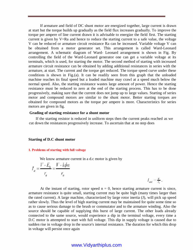
If armature and field of DC shunt motor are energized together, large current is drawn
at start but the torque builds up gradually as the field flux increases gradually. To improve the
torque per ampere of line current drawn it is advisable to energize the field first. The starting
current is given by V=Ra and hence to reduce the starting current to a safe value, the voltage
V can be reduced or armature circuit resistance Ra can be increased. Variable voltage V can
be obtained from a motor generator set. This arrangement is called Ward-Leonard
arrangement. A schematic diagram of Ward- Leonard arrangement is shown in Fig. By
controlling the field of the Ward-Leonard generator one can get a variable voltage at its
terminals, which is used, for starting the motor. The second method of starting with increased
armature circuit resistance can be obtained by adding additional resistances in series with the
armature, at start. The current and the torque get reduced. The torque speed curve under these
conditions is shown in Fig.(a). It can be readily seen from this graph that the unloaded
machine reaches its final speed but a loaded machine may crawl at a speed much below the
normal speed. Also, the starting resistance wastes large amount of power. Hence the starting
resistance must be reduced to zero at the end of the starting process. This has to be done
progressively, making sure that the current does not jump up to large values. Starting of series
motor and compound motors are similar to the shunt motor. Better starting torques are
obtained for compound motors as the torque per ampere is more. Characteristics for series
motors are given in fig.
At the instant of starting, rotor speed n = 0, hence starting armature current is since,
armature resistance is quite small, starting current may be quite high (many times larger than
the rated current). A large machine, characterized by large rotor inertia (J), will pick up speed
rather slowly. Thus the level of high starting current may be maintained for quite some time so
as to cause serious damage to the brush or commutator and to the armature winding. Also the
source should be capable of supplying this burst of large current. The other loads already
connected to the same source, would experience a dip in the terminal voltage, every time a
D.C motor is attempted to start with full voltage. This dip in supply voltage is caused due to
sudden rise in voltage drop in the source's internal resistance. The duration for which this drop
in voltage will persist once again
We know armature current in a d.c motor is given by
1. Problems of starting with full voltage
Starting of D.C shunt motor
If the starting resistor is reduced in uniform steps then the current peaks reached as we
cut down the resistances progressively increase. To ascertain that at no step does
Grading of starting resistance for a shunt motor .
www.Vidyarthiplus.comwww.Vidyarthiplus.com

Depends on inertia (size) of the motor. Hence, for small D.C motors extra precaution may not
be necessary during starting as large starting current will very quickly die down because of
fast rise in the back emf. However, for large motor, a starter is to be used during starting.
2. A simple starter
To limit the starting current, a suitable external resistance R ext is connected in
series (Figure (a)) with the armature so that at the time of starting, to have sufficient
starting torque, field current is maximized by keeping the external field resistance Rf,
to zero value.
As the motor picks up speed, the value of R ext is gradually decreased to zero so that
during running no external resistance remains in the armature circuit. But each time one has to
restart the motor, the external armature resistance must be set to maximum value by moving
the jockey manually.
Now if the supply goes off (due to some problem in the supply side or due to load
shedding), motor will come to a stop. All on a sudden, let us imagine, supply is restored. This
is then nothing but full voltage starting. In other words, one should be constantly alert to set
the resistance to maximum value whenever the motor comes to a stop. This is one major
limitation of a simple rheostat starter.
3. 3-point starter
A “3-point starter” is extensively used to start a D.C shunt motor. It not only overcomes
the difficulty of a plain resistance starter, but also provides additional protective features such
as over load protection and no volt protection. The diagram of a 3-point starter connected to a
shunt motor is shown in figure . Although, the circuit looks a bit clumsy at a first glance, the
basic working principle is same as that of plain resistance starter The starter is shown enclosed
within the dotted rectangular box having
Imagine, the motor to be running with R ext = 0 (Figure (b)).
www.Vidyarthiplus.comwww.Vidyarthiplus.com
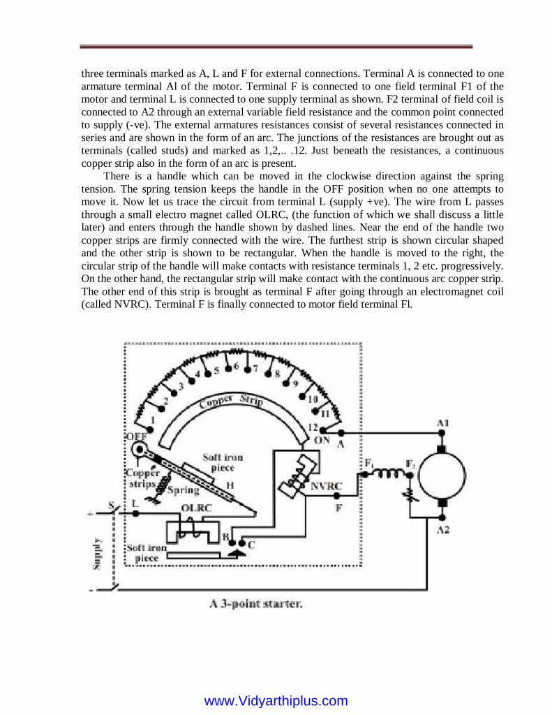
three terminals marked as A, L and F for external connections. Terminal A is connected to one
armature terminal Al of the motor. Terminal F is connected to one field terminal F1 of the
motor and terminal L is connected to one supply terminal as shown. F2 terminal of field coil is
connected to A2 through an external variable field resistance and the common point connected
to supply (-ve). The external armatures resistances consist of several resistances connected in
series and are shown in the form of an arc. The junctions of the resistances are brought out as
terminals (called studs) and marked as 1,2,.. .12. Just beneath the resistances, a continuous
copper strip also in the form of an arc is present.
There is a handle which can be moved in the clockwise direction against the spring
tension. The spring tension keeps the handle in the OFF position when no one attempts to
move it. Now let us trace the circuit from terminal L (supply +ve). The wire from L passes
through a small electro magnet called OLRC, (the function of which we shall discuss a little
later) and enters through the handle shown by dashed lines. Near the end of the handle two
copper strips are firmly connected with the wire. The furthest strip is shown circular shaped
and the other strip is shown to be rectangular. When the handle is moved to the right, the
circular strip of the handle will make contacts with resistance terminals 1, 2 etc. progressively.
On the other hand, the rectangular strip will make contact with the continuous arc copper strip.
The other end of this strip is brought as terminal F after going through an electromagnet coil
(called NVRC). Terminal F is finally connected to motor field terminal Fl.
www.Vidyarthiplus.comwww.Vidyarthiplus.com
4. Working principle
Let us explain the operation of the starter. Initially the handle is in the OFF position.
Neither armature nor the field of the motor gets supply. Now the handle is moved to stud
number 1. In this position armature and all the resistances in series gets connected to the
supply. Field coil gets full supply as the rectangular strip makes contact with arc copper strip.
As the machine picks up speed handle is moved further r to stud number 2. In this position the
external resistance in the armature circuit is less as the first resistance is left out. Field
however, continues to get full voltage by virtue of the continuous arc strip. Continuing in this
way, all resistances will be left out when stud number 12 (ON) is reached. In this position, the
electromagnet (NVRC) will attract the soft iron piece attached to the handle. Even if the
operator removes his hand from the handle, it will still remain in the ON position as spring
restoring force will be balanced by the force of attraction between NVRC and the soft iron
piece of the handle. The no volt release coil (NVRC) carries same current as that of the field
coil. In case supply voltage goes off, field coil current will decrease to zero. Hence NVRC will
be reenergized and will not be able to exert any force on the soft iron piece of the handle.
Restoring force of the spring will bring the handle back in the OFF position.
The starter also provides over load protection for the motor. The other electromagnet,
OLRC overload release coil along with a soft iron piece kept under it, is used to achieve this.
The current flowing through OLRC is the line current IL drawn by the motor. As the motor is
loaded, Ia hence IL increases. Therefore, IL is a measure of loading of the motor. Suppose we
want that the motor should not be over loaded beyond rated current. Now gap between the
electromagnet and the soft iron piece is so adjusted
that forth iron piece will not be pulled up. However, if rated I I force of attraction will be
sufficient to pull up iron piece. This upward movement of the iron piece of OLRC is utilized
to de-energize NVRC. To the iron a copper strip (Ä shaped in figure) is attached. During over
loading condition, this copper strip will also move up and put a short circuit between two
terminals B and C. Carefully note that B and C are nothing but the two ends of the NVRC. In
other words, when over load occurs a short circuit path is created across the NVRC. Hence
NVRC will not carry any current now and gets reenergized. The moment it gets reenergized,
spring action will bring the handle in the OFF position thereby disconnecting the motor from
the supply.
Three-point starter has one disadvantage. If we want to run the machine at higher speed
(above rated speed) by field weakening (i.e., by reducing field current), the strength of NVRC
magnet may become so weak that it will fail to hold the handle in the ON position and the
spring action will bring it back in the OFF position. Thus we find that a false disconnection of
the motor takes place even when there is neither over load nor any sudden disruption of
supply.
DIFFERENT TYPES OF STARTERS FOR 3 PHASE INDUCTION MOTOR (IM)
INSTRUCTIONAL OBJECTIVES
www.Vidyarthiplus.comwww.Vidyarthiplus.com

• Need of using starters for Induction motor
• Two (Star-Delta and Auto-transformer) types of starters used for Squirrel cage Induction
motor
• Starter using additional resistance in rotor circuit, for Wound rotor (Slip-ring) Induction
motor
Introduction
Induction motors can be started Direct-on-Line (DOL), which means that the rated
voltage is supplied to the stator, with the rotor terminals short-circuited in a wound rotor (slip-
ring) motor. For the cage rotor, the rotor bars are short circuited via two end rings. Neglecting
stator impedance, the starting current in the stator windings
Direct-on-Line (DOL) Starters
Direct-on-Line (DOL) starter, Star-delta starter, auto-transformer starter, rotor resistance
starter, starting current, starting torque, starters for squirrel cage and wound rotor induction
motor, need for starters.
In the previous, i.e. fourth, lesson of this module, the expression of gross torque
developed, as a function of slip (speed), in IM has been derived first. The sketches of the
different torque-slip (speed) characteristics, with the variations in input (stator) voltage and
rotor resistance, are presented, along with the explanation of their features. Lastly, the
expression of maximum torque developed and also the slip, where it occurs, have been
derived. In this lesson, starting with the need for using starters in IM to reduce the starting
current, first two (Star-Delta and Auto-transformer) types of starters used for Squirrel cage IM
and then, the starter using additional resistance in rotor circuit, for Wound rotor (Slip-ring)
IM, are presented along with the starting current drawn from the input (supply) voltage, and
also the starting torque developed using the above starters.
www.Vidyarthiplus.comwww.Vidyarthiplus.com

Need for Starters in IM
torque is which shows that, as the starting current increases, the starting torque also increases.
This results in higher accelerating torque (minus the load torque and the torque component of
the losses), with the motor reaching rated or near rated speed quickly.
The input voltage per phase to the stator is equal to the induced emf per phase in the stator
winding, as the stator impedance is neglected (also shown in the last lesson (#32)). In the
formula for starting current, no load current is neglected. It may be noted that the starting
current is quite high, about 4-6 times the current at full load, may be higher, depending on the
rating of IM, as compared to no load current. The starting
www.Vidyarthiplus.comwww.Vidyarthiplus.com

Starters for Cage IM
the motor (stator), i.e.
The starting current in IM is proportional to the input voltage per phase
, where,
The main problem in starting induction motors having large or medium size lies
mainly in the requirement of high starting current, when started direct-on-line (DOL). Assume
that the distribution line is starting from a substation (Fig.), where the supply voltage is
constant. The line feeds a no. of consumers, of which one consumer has an induction motor
with a DOL starter, drawing a high current from the line, which is higher than the current for
which this line is designed. This will cause a drop (dip) in the voltage, all along the line, both
for the consumers between the substation and this consumer, and those, who are in the line
after this consumer. This drop in the voltage is more than the drop permitted, i.e. higher than
the limit as per ISS, because the current drawn is more than the current for which the line is
designed. Only for the current lower the current for which the line is designed, the drop in
voltage is lower the limit. So, the supply authorities set a limit on the rating or size of IM,
which can be started DOL. Any motor exceeding the specified rating, is not permitted to be
started DOL, for which a starter is to be used to reduce the current drawn at starting.
to
as the voltage drop in the
stator impedance is small compared to the input voltage, or if the stator impedance is
neglected. This has been shown earlier. So, in a (squirrel) cage induction motor, the starter is
used only to decrease the input voltage to the motor so as to decrease the starting current. As
described later, this also results in decrease of starting torque.
www.Vidyarthiplus.comwww.Vidyarthiplus.com

www.Vidyarthiplus.comwww.Vidyarthiplus.com

is of the starting current, if DOL starter is used. The voltage per phase in each stator
winding is now (. 3 / s V ). So, the starting current using star-delta starter is reduced by 33.3%.
As for starting torque, being proportional to the square of the current in each of the stator
windings in two different connections as shown earlier, is also reduced by ( 2 ) 3 / 1 ( 3 / 1 = ),
as the ratio of the two currents is ( 3 / 1 ), same as that (ratio) of the voltages applied to each
winding as shown earlier. So, the starting torque is reduced by 33.3%, which is a disadvantage
of the use of this starter. The load torque and the loss torque, must be lower than the starting
torque, if the motor is to be started using this starter. The advantage is that, no extra
component, except that shown in Fig. 33.2c, need be used, thus making it simple. As shown
later, this is an auto-transformer starter with the voltage ratio as 57.7%. Alternatively, the
starting current in the second case with the stator winding reconnected as star, can be found by
using star-
phase or line current drawn from supply at start (standstill) is
the input current to the motor is which is the current, if the motor is started direct-on-line
(DOL). Now, if the stator winding is connected as star, the
, where is the impedance of the motor per phase at standstill or start (stator impedance
and rotor impedance referred to the stator, at standstill). The line current or
This type is used for the induction motor, the stator winding of which is nominally delta-
connected (Fig. 33.2a). If the above winding is reconnected as star (Fig.33.2b), the voltage per
phase supplied to each winding is reduced by 3(.577). This is a simple starter, which can
be easily reconfigured as shown in Fig. 33.2c. As the voltage per phase in delta connection is
V s, the phase current in each stator winding is
which
www.Vidyarthiplus.comwww.Vidyarthiplus.com
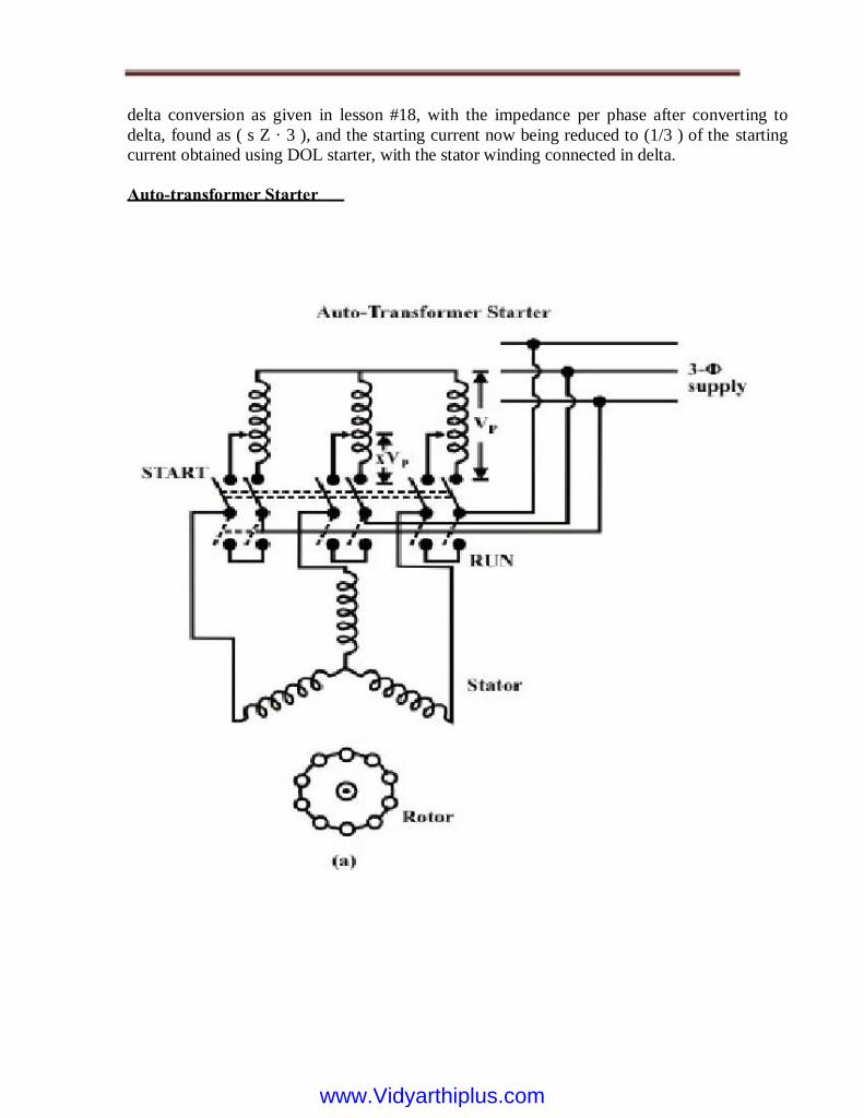
delta conversion as given in lesson #18, with the impedance per phase after converting to
delta, found as ( s Z · 3 ), and the starting current now being reduced to (1/3 ) of the starting
current obtained using DOL starter, with the stator winding connected in delta.
Auto-transformer Starter
www.Vidyarthiplus.comwww.Vidyarthiplus.com

Let be the starting current, when the motor is started using DOL starter, (i.e.,) applying
rated input voltage. The input current of IM, which is the output current of auto-transformer,
when this starter is used with input voltage. The input current of auto-transformer, which is
the starting current drawn from the supply, is obtained by equating input and output volt-
amperes, neglecting losses and assuming nearly same power factor on both sides. As
discussed earlier, the starting torque, being proportional to the square of the input current to
IM in two cases, with and without auto-transformer (i.e. direct), is also reduced by , as the
ratio of the two currents is same as that (ratio) of the voltages applied to the motor as shown
earlier. So, the starting torque is reduced by the same ratio as that of the starting current.
If the ratio is both starting current and torque are %) 80 ( 8 . 0 = x %) 64 ( 64 . 0) 8 . 0 (
2 2 = = x times the values of starting current and torque with DOL starting, which is nearly 2
times the values obtained using star-delta starter. So, the disadvantage is that starting current is
increased, with the result that lower rated motor can now be started, as the current drawn from
the supply is to be kept within limits, while the advantage is that the starting torque is now
doubled, such that the motor can start against higher load torque. The star-delta starter can be
considered equivalent to an autotransformer starter with the ratio, %) 7 . 57 ( 577 . 0 = x . If
%) 70 ( 7 . 0 = x , both starting current and
An auto-transformer, whose output is fed to the stator and input is from the supply
(Fig. 33.3), is used to start the induction motor. The input voltage of IM is, which is the output
voltage of the auto-transformer, the input voltage being V s. The output voltage/input voltage
ratio is x , the value of which lies between 0.0 and 1.0
www.Vidyarthiplus.comwww.Vidyarthiplus.com
torque are times the values of starting current and torque with DOL starting, which is nearly
1.5 times the values obtained using star delta starter.
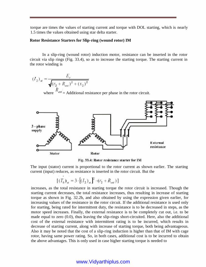
Rotor Resistance Starters for Slip-ring (wound rotor) IM
In a slip-ring (wound rotor) induction motor, resistance can be inserted in the rotor
circuit via slip rings (Fig. 33.4), so as to increase the starting torque. The starting current in
the rotor winding is
where = Additional resistance per phase in the rotor circuit.
increases, as the total resistance in starting torque the rotor circuit is increased. Though the
starting current decreases, the total resistance increases, thus resulting in increase of starting
torque as shown in Fig. 32.2b, and also obtained by using the expression given earlier, for
increasing values of the resistance in the rotor circuit. If the additional resistance is used only
for starting, being rated for intermittent duty, the resistance is to be decreased in steps, as the
motor speed increases. Finally, the external resistance is to be completely cut out, i.e. to be
made equal to zero (0.0), thus leaving the slip-rings short-circuited. Here, also the additional
cost of the external resistance with intermittent rating is to be incurred, which results in
decrease of starting current, along with increase of starting torque, both being advantageous.
Also it may be noted that the cost of a slip-ring induction is higher than that of IM with cage
rotor, having same power rating. So, in both cases, additional cost is to be incurred to obtain
the above advantages. This is only used in case higher starting torque is needed to
The input (stator) current is proportional to the rotor current as shown earlier. The starting
current (input) reduces, as resistance is inserted in the rotor circuit. But the
www.Vidyarthiplus.comwww.Vidyarthiplus.com

start IM with high load torque. It may be observed from Fig. 32.2b that the starting torque
increases till it reaches maximum value,
rotor circuit is increased, the range of total resistance being
The range of external resistance is between
zero (0.0) and
torque is equal to the maximum value, i.e.
inserted is equal to
further,
2 r x -). The starting
if the external resistance
the external resistance in the
if the external resistance in the rotor circuit is increased
the starting torque decreases. This is, because the
STARTING METHODS FOR SINGLE-PHASE INDUCTION MOTOR
Instructional Objectives
• Why there is no starting torque in a single-phase induction motor with one (main) winding in
the stator?
• Various starting methods used in the single-phase induction motors, with the introduction of
additional features, like the addition of another winding in the stator, and/or capacitor in series
with it.
Introduction
In the previous, i.e. fifth, lesson of this module, the direct-on-line (DOL) starter used
in three-phase IM, along with the need for starters, has been described first. Two types of
starters - star-delta, for motors with nominally delta-connected stator winding, and
autotransformer, used for cage rotor IM, are then presented, where both decrease in starting
current and torque occur. Lastly, the rotor resistance starter for slip-ring (wound rotor) IM has
been discussed, where starting current decreases along with increase in starting torque. In all
such
This is, because the starting current decreases at a faster rate, even if the total
resistance in the rotor circuit is increased.
In this lesson - the fifth one of this module, the direct-on-line (DOL) starter used for
IM, along with the need for other types of starters, has been described first. Then, two types of
starters - star-delta and autotransformer, for cage type IM, are presented. Lastly, the rotor
resistance starter for slip-ring (wound rotor) IM is briefly described. In the next (sixth and last)
lesson of this module, the various types of single-phase induction motors, along with the
starting methods, will be presented.
www.Vidyarthiplus.comwww.Vidyarthiplus.com
cases, additional cost is to be incurred. In the last (sixth) lesson of this module, firstly it is
shown that there is no starting torque in a single-phase induction motor with only one (main)
winding in the stator. Then, the various starting methods used for such motors, like, say, the
addition of another (auxiliary) winding in the stator, and/or capacitor in series with it.
Keywords:
Single-phase induction motor, starting torque, main and auxiliary windings, starting
methods, split-phase, capacitor type, motor with capacitor start/run.
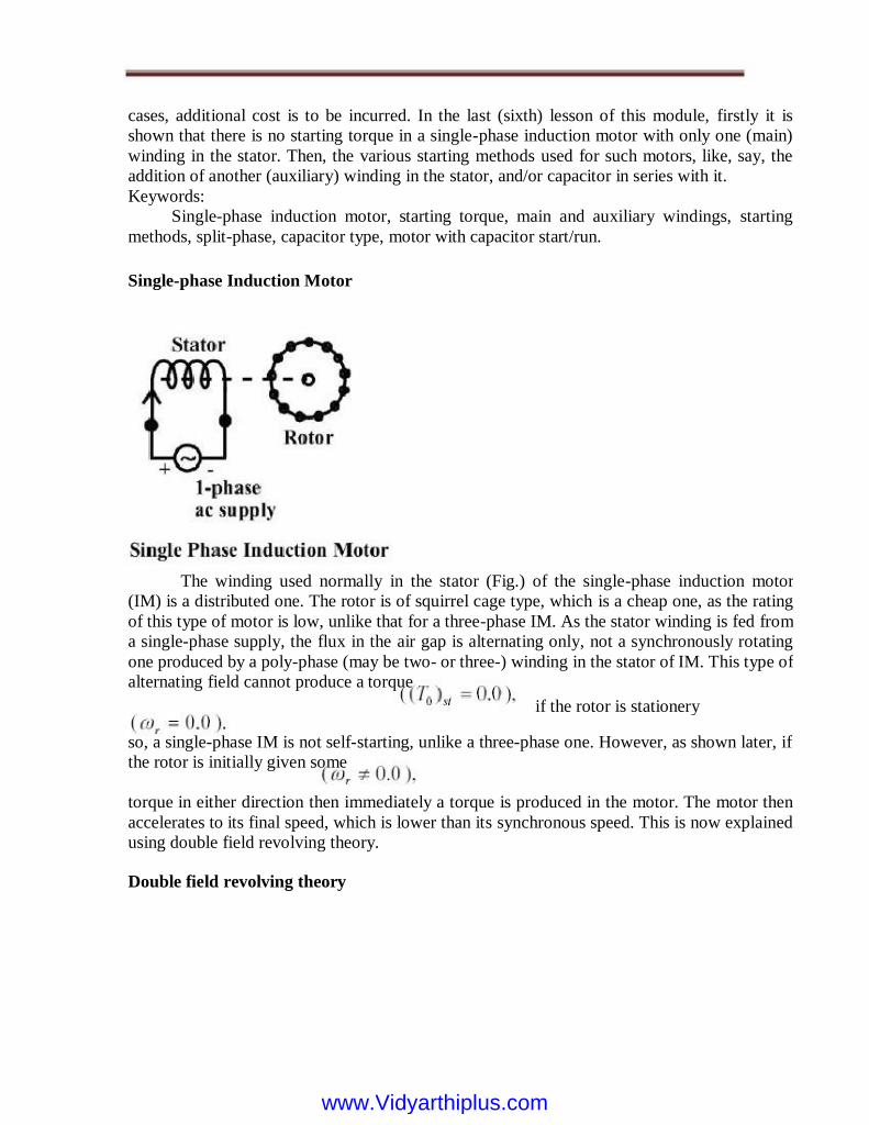
Single-phase Induction Motor
The winding used normally in the stator (Fig.) of the single-phase induction motor
(IM) is a distributed one. The rotor is of squirrel cage type, which is a cheap one, as the rating
of this type of motor is low, unlike that for a three-phase IM. As the stator winding is fed from
a single-phase supply, the flux in the air gap is alternating only, not a synchronously rotating
one produced by a poly-phase (may be two- or three-) winding in the stator of IM. This type of
alternating field cannot produce a torque
if the rotor is stationery
torque in either direction then immediately a torque is produced in the motor. The motor then
accelerates to its final speed, which is lower than its synchronous speed. This is now explained
using double field revolving theory.
Double field revolving theory
so, a single-phase IM is not self-starting, unlike a three-phase one. However, as shown later, if
the rotor is initially given some
www.Vidyarthiplus.comwww.Vidyarthiplus.com

in opposite directions. This is shown in Fig. The first set of figures (Fig. 34.1a (i-iv)) show the
resultant sum of the two rotating fluxes or fields, as the time axis (angle) is changing from Fig.
shows the alternating or pulsating flux (resultant)
varying with time or angle.
When the stator winding (distributed one as stated earlier) carries a sinusoidal current (being
fed from a single-phase supply), a sinusoidal space distributed mmf, whose peak or maximum
value pulsates (alternates) with time, is produced in the air gap. This sinusoidal varying flux is
the sum of two rotating fluxes or fields, the magnitude of
which is equal to half the value of the alternating flux
and both the fluxes rotating synchronously at the speed,
www.Vidyarthiplus.comwww.Vidyarthiplus.com
(space
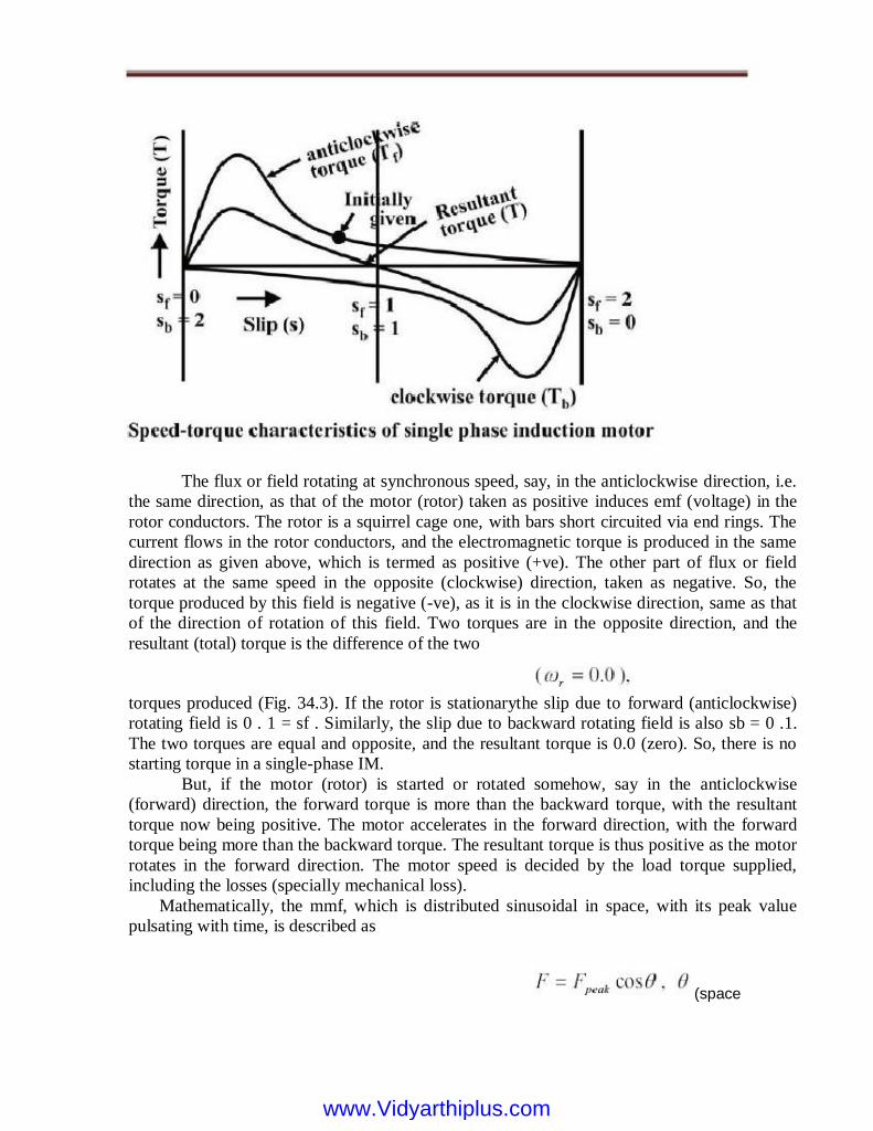
torques produced (Fig. 34.3). If the rotor is stationarythe slip due to forward (anticlockwise)
rotating field is 0 . 1 = sf . Similarly, the slip due to backward rotating field is also sb = 0 .1.
The two torques are equal and opposite, and the resultant torque is 0.0 (zero). So, there is no
starting torque in a single-phase IM.
But, if the motor (rotor) is started or rotated somehow, say in the anticlockwise
(forward) direction, the forward torque is more than the backward torque, with the resultant
torque now being positive. The motor accelerates in the forward direction, with the forward
torque being more than the backward torque. The resultant torque is thus positive as the motor
rotates in the forward direction. The motor speed is decided by the load torque supplied,
including the losses (specially mechanical loss).
Mathematically, the mmf, which is distributed sinusoidal in space, with its peak value
pulsating with time, is described as
The flux or field rotating at synchronous speed, say, in the anticlockwise direction, i.e.
the same direction, as that of the motor (rotor) taken as positive induces emf (voltage) in the
rotor conductors. The rotor is a squirrel cage one, with bars short circuited via end rings. The
current flows in the rotor conductors, and the electromagnetic torque is produced in the same
direction as given above, which is termed as positive (+ve). The other part of flux or field
rotates at the same speed in the opposite (clockwise) direction, taken as negative. So, the
torque produced by this field is negative (-ve), as it is in the clockwise direction, same as that
of the direction of rotation of this field. Two torques are in the opposite direction, and the
resultant (total) torque is the difference of the two
www.Vidyarthiplus.comwww.Vidyarthiplus.com

angle) measured from the winding axis. Now,
is distributed both in space and time, i.e. it can be
expressed as,
So, the mmf
which shows that a pulsating field can be considered as the sum of two synchronously rotating
fields
and the backward rotating field is
The forward rotating field is,
Both the fields have the same amplitude equal to
with angular speed the slip due to the forward rotating field is,
is the maximum value of the pulsating mmf along the axis of the winding. When
the motor rotates in the forward (anticlockwise) direction
Similarly, the slip
due to the backward rotating field, the speed of which is
The resultant torque is,
It was earlier shown that, when the rotor is stationary,
with both as
The torque produced by the two fields is in opposite direction.
Therefore, the resultant torque at start is 0.0 (zero).
STARTING METHODS
The single-phase IM has no starting torque, but has resultant torque, when it rotates at
any other speed, except synchronous speed. It is also known that, in a balanced two-phase IM
having two windings, each having equal number of turns and placed at a space angle of 90o
(electrical), and are fed from a balanced two-phase supply, with two voltages equal in
magnitude, at an angle of 90o, the rotating magnetic fields are produced, as in a three-phase
IM. The torque-speed characteristic is same as that of a three-phase one, having both starting
and also running torque as shown earlier. So, in a single-phase IM, if an auxiliary winding is
introduced in the stator, in addition to the main winding, but placed at a space angle of 90o
(electrical), starting torque is produced.
www.Vidyarthiplus.comwww.Vidyarthiplus.com
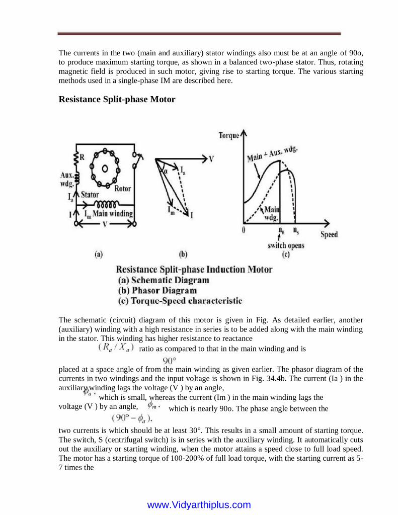
The currents in the two (main and auxiliary) stator windings also must be at an angle of 90o,
to produce maximum starting torque, as shown in a balanced two-phase stator. Thus, rotating
magnetic field is produced in such motor, giving rise to starting torque. The various starting
methods used in a single-phase IM are described here.
Resistance Split-phase Motor
The schematic (circuit) diagram of this motor is given in Fig. As detailed earlier, another
(auxiliary) winding with a high resistance in series is to be added along with the main winding
in the stator. This winding has higher resistance to reactance
placed at a space angle of from the main winding as given earlier. The phasor diagram of the
currents in two windings and the input voltage is shown in Fig. 34.4b. The current (Ia ) in the
auxiliary winding lags the voltage (V ) by an angle,
which is small, whereas the current (Im ) in the main winding lags the
which is nearly 90o. The phase angle between the voltage (V ) by an angle,
two currents is which should be at least 30°. This results in a small amount of starting torque.
The switch, S (centrifugal switch) is in series with the auxiliary winding. It automatically cuts
out the auxiliary or starting winding, when the motor attains a speed close to full load speed.
The motor has a starting torque of 100-200% of full load torque, with the starting current as 5-
7 times the
ratio as compared to that in the main winding and is
www.Vidyarthiplus.comwww.Vidyarthiplus.com

full load current. The torque-speed characteristics of the motor with/without auxiliary winding
are shown in Fig. The change over occurs, when the auxiliary winding is switched off as given
earlier. The direction of rotation is reversed by reversing the terminals of any one of two
windings, but not both, before connecting the motor to the supply terminals. This motor is
used in applications, such as fan, saw, small lathe, centrifugal pump, blower, office
equipment, washing machine, etc.
The motor described earlier, is a simple one, requiring only second (auxiliary) winding placed
at a space angle of 90 o from the main winding, which is there in nearly all such motors as
discussed here. It does not need any other thing, except for centrifugal switch, as the auxiliary
winding is used as a starting winding. But the main problem is low starting torque in the
motor, as this torque is a function of, or related to the phase difference (angle) between the
currents in the two windings. To get high starting torque, the phase difference required is
90°(Fig. 34.5b), when the starting torque will be proportional to the product of the magnitudes
of two currents. As the current in the main winding is lagging by
Capacitor-start Motor
is taken as negative (-ve), while is positive (+ve). This can be can be achieved by having a
capacitor in series with the auxiliary winding, which results in additional cost, with the
increase in starting torque. The two types of such motors are described here.
the current in the auxiliary winding has to lead the input voltage by with
www.Vidyarthiplus.comwww.Vidyarthiplus.com

Capacitor-start and Capacitor-run Motor
The schematic (circuit) diagram of this motor is given in Fig. It may be observed that a
capacitor along with a centrifugal switch is connected in series with the auxiliary winding,
which is being used here as a starting winding. The capacitor may be rated only for
intermittent duty, the cost of which decreases, as it is used only at the time of starting. The
function of the centrifugal switch has been described earlier. The phasor diagram of two
currents as described earlier, and the torque-speed characteristics of the motor with/without
auxiliary winding, are shown in Fig. respectively. This motor is used in applications, such as
compressor, conveyor, machine tool drive, refrigeration and air-conditioning equipment, etc.
www.Vidyarthiplus.comwww.Vidyarthiplus.com
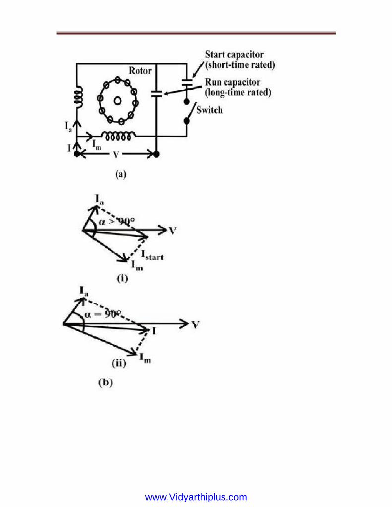
www.Vidyarthiplus.comwww.Vidyarthiplus.com

in the first case (starting), while it is for between the two currents is 90° second case
(running). In the second case, the motor is a balanced two phase one, the two windings having
same number of turns and other conditions as given earlier, are also satisfied. So, only the
forward rotating field is present, and the no backward rotating field exists. The efficiency of
the motor under this condition is higher. Hence, using two capacitors, the performance of the
motor improves both at the time of starting and then running. This motor is used in
applications, such as compressor, refrigerator, etc.
In this motor (Fig. 34.6a), two capacitors -Cs for starting, and Cr for running, are used.
The first capacitor is rated for intermittent duty, as described earlier, being used only for
starting. A centrifugal switch is also needed here. The second one is to be rated for continuous
duty, as it is used for running. The phasor diagram of two currents in both cases, and the
torque-speed characteristics with two windings having different values of capacitors, are
shown in Fig. 34.6b and Fig. 34.6c respectively. The phase difference
www.Vidyarthiplus.comwww.Vidyarthiplus.com

Shaded-pole Motor
Let the main winding flux be
A typical shaded-pole motor with a cage rotor is shown in Fig. This is a single phase
induction motor, with main winding in the stator. A small portion of each pole is covered with
a short-circuited, single-turn copper coil called the shading coil. The sinusoidal varying flux
created by ac (single-phase) excitation of the main winding induces emf in the shading coil.
As a result, induced currents flow in the shading coil producing their own flux in the shaded
portion of the pole.
Beside the above two types of motors, a Permanent Capacitor Motor (Fig.) with the
same capacitor being utilized for both starting and running, is also used. The power factor of
this motor, when it is operating (running), is high. The operation is also quiet and smooth.
This motor is used in applications, such as ceiling fans, air circulator, blower, etc.
www.Vidyarthiplus.comwww.Vidyarthiplus.com
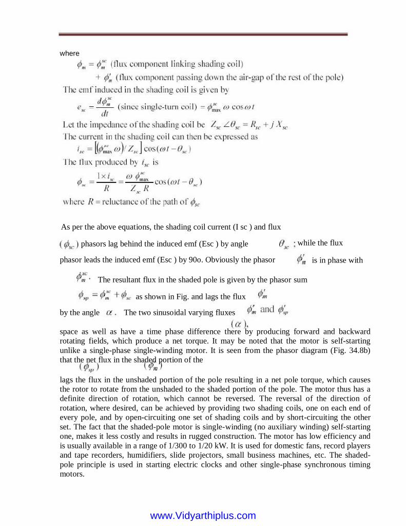
where
As per the above equations, the shading coil current (I sc ) and flux
phasors lag behind the induced emf (Esc ) by angle
while the flux
is in phase with
by the angle
The resultant flux in the shaded pole is given by the phasor sum
lags the flux in the unshaded portion of the pole resulting in a net pole torque, which causes
the rotor to rotate from the unshaded to the shaded portion of the pole. The motor thus has a
definite direction of rotation, which cannot be reversed. The reversal of the direction of
rotation, where desired, can be achieved by providing two shading coils, one on each end of
every pole, and by open-circuiting one set of shading coils and by short-circuiting the other
set. The fact that the shaded-pole motor is single-winding (no auxiliary winding) self-starting
one, makes it less costly and results in rugged construction. The motor has low efficiency and
is usually available in a range of 1/300 to 1/20 kW. It is used for domestic fans, record players
and tape recorders, humidifiers, slide projectors, small business machines, etc. The shaded-
pole principle is used in starting electric clocks and other single-phase synchronous timing
motors.
space as well as have a time phase difference there by producing forward and backward
rotating fields, which produce a net torque. It may be noted that the motor is self-starting
unlike a single-phase single-winding motor. It is seen from the phasor diagram (Fig. 34.8b)
that the net flux in the shaded portion of the
The two sinusoidal varying fluxes
as shown in Fig. and lags the flux
phasor leads the induced emf (Esc ) by 90o. Obviously the phasor
www.Vidyarthiplus.comwww.Vidyarthiplus.com

In this lesson - the sixth and last one of this module, firstly, it is shown that, no starting
torque is produced in the single-phase induction motor with only one (main) stator winding, as
the flux produced is a pulsating one, with the winding being fed from single phase supply.
Using double revolving field theory, the torque-speed characteristics of this type of motor are
described, and it is also shown that, if the motor is initially given some torque in either
direction, the motor accelerates in that direction, and also the torque is produced in that
direction. Then, the various types of single-phase induction motors, along with the starting
methods used in each one are presented. Two stator windings - main and auxiliary, are needed
to produce the starting torque. The merits and demerits of each type, along with their
application area, are presented. The process of production of starting torque in shade-pole
motor is also described in brief. In the next module consisting of seven lessons, the
construction and also operation of dc machines, both as generator and motor, will be
discussed.
www.Vidyarthiplus.comwww.Vidyarthiplus.com
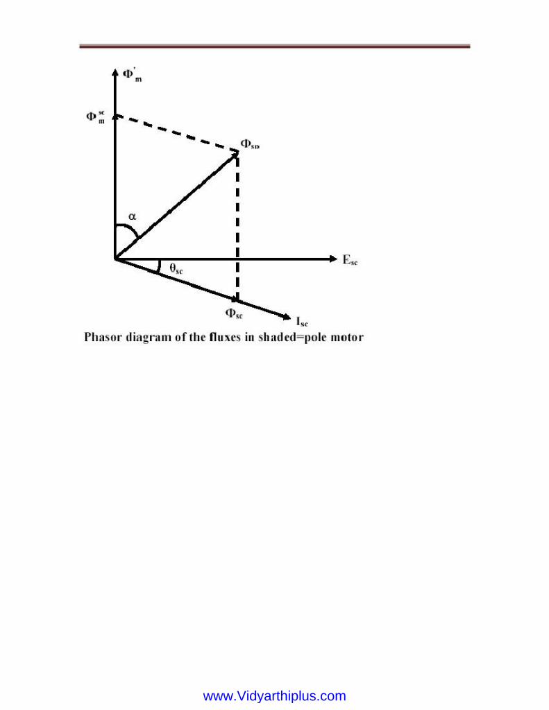
www.Vidyarthiplus.comwww.Vidyarthiplus.com
UNIT-IV
CONVENTIONAL AND SOLID STATE SPEED CONTROL OF D.C. DRIVES
SPEED CONTROL OF D.C. MOTORS
In the case of speed control, armature voltage control and flux control methods are
available. The voltage control can be from a variable voltage source like Ward-Leonard
arrangement or by the use of series armature resistance. Unlike the starting conditions the
series resistance has to be in the circuit throughout in the case of speed control. That means
considerable energy is lost in these resistors. Further these resistors must be adequately cooled
for continuous operation. The variable voltage source on the other hand gives the motor the
voltage just needed by it and the losses in the control gear is a minimum. This method is
commonly used when the speed ratio required is large, as also the power rating.
Field control or flux control is also used for speed control purposes. Normally field
weakening is used. This causes operation at higher speeds than the nominal speed.
Strengthening the field has little scope for speed control as the machines are already in a state
of saturation and large field mmf is needed for small increase in the flux. Even though flux
weakening gives higher speeds of operation it reduces the torque produced by the machine for
a given armature current and hence the power delivered does not increase at any armature
current. The machine is said to be in constant power mode under field weakening mode of
control. Above the nominal speed of operation, constant ux mode with increased applied
voltage can be used; but this is never done as the stress on the commutator insulation
increases.
Thus operation below nominal speed is done by voltage control. Above the nominal
speed field weakening is adopted. For weakening the field, series resistances are used for
shunt as well as compound motors. In the case of series motors however field weakening is
done by the use of „diverters‟. Diverters are resistances that are connected in parallel to the
series winding to reduce the field current without affecting the armature current.
We know that the speed of shunt motor is given by:
where, Va is the voltage applied across the armature and ö is the flux per pole and is
proportional to the field current If. As explained earlier, armature current Ia is decided by the
mechanical load present on the shaft. Therefore, by varying Va and If we can vary n. For fixed
supply voltage and the motor connected as shunt we can vary Va by controlling an external
resistance connected in series with the armature. If of course can be varied by controlling
external field resistance Rf connected with the field circuit. Thus for shunt motor we have
essentially two methods for controlling speed, namely by:
Speed control of shunt motor
www.Vidyarthiplus.comwww.Vidyarthiplus.com

1. varying armature resistance.
2. varying field resistance.
1. Speed control by varying armature resistance
The inherent armature resistance ra being small, speed n versus armature current Ia
characteristic will be a straight line with a small negative slope as shown in figure. In the
discussion to follow we shall not disturb the field current from its rated value. At no
load (i.e., Ia = 0) speed is highest and Note that for shunt motor voltage applied to the field
and armature circuit are same and equal to the supply voltage V. However, as the motor is
loaded, Ia ra drop increases making speed a little less than the no load speed n0. For a well-
designed shunt motor this drop in speed is small and about 3 to 5% with respect to no load
speed. This drop in speed from no load to full load condition expressed as a percentage of no
load speed is called the inherent speed regulation of the motor.
It is for this reason, a d.c shunt motor is said to be practically a constant speed motor
(with no external armature resistance connected) since speed drops by a small amount from no
load to full load condition.
Since for constant operation, Te becomes simply proportional to Ia. Therefore, speed vs.
torque characteristic is also similar to speed vs. armature current characteristic as shown in
figure. The slope of the n vs Ia or n vs Te characteristic can be modified by deliberately
connecting external resistance rext in the armature circuit. One can get a family of speed
www.Vidyarthiplus.comwww.Vidyarthiplus.com

vs. armature curves as shown in figures for various values of r ext. From these characteristics
it can be explained how speed control is achieved. Let us assume that the load torque TL is
constant and field current is also kept constant. Therefore, since steady state operation
demands Te = TL, Te = a k I ö too will remain constant; which means Ia will not change.
Suppose rext = 0, then at rated load torque, operating point will be at C and motor speed will
be n. If additional resistance rext1 is introduced in the armature circuit, new steady state
operating speed will be n1 corresponding to the operating point D. In this way one can get a
speed of n2 corresponding to the operating point E, when rext2 is introduced in the armature
circuit. This same load torque is supplied at various speed. Variation of the speed is smooth
and speed will decrease smoothly if r ext is increased.
Obviously, this method is suitable for controlling speed below the base speed and for
supplying constant rated load torque which ensures rated armature current always. Although,
this method provides smooth wide range speed control (from base speed down to zero speed),
has a serious draw back since energy loss takes place in the external resistance r ext reducing
the efficiency of the motor.
www.Vidyarthiplus.comwww.Vidyarthiplus.com
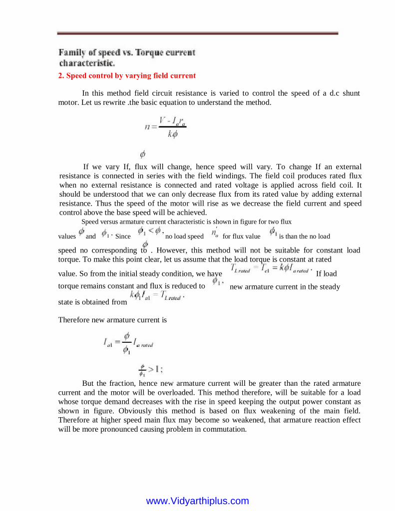
2. Speed control by varying field current
In this method field circuit resistance is varied to control the speed of a d.c shunt
motor. Let us rewrite .the basic equation to understand the method.
torque remains constant and flux is reduced to
state is obtained from
value. So from the initial steady condition, we have
speed no corresponding to . However, this method will not be suitable for constant load
torque. To make this point clear, let us assume that the load torque is constant at rated
values and Since no load speed
Speed versus armature current characteristic is shown in figure for two flux
for flux value is than the no load
If we vary If, flux will change, hence speed will vary. To change If an external
resistance is connected in series with the field windings. The field coil produces rated flux
when no external resistance is connected and rated voltage is applied across field coil. It
should be understood that we can only decrease flux from its rated value by adding external
resistance. Thus the speed of the motor will rise as we decrease the field current and speed
control above the base speed will be achieved.
If load
new armature current in the steady
Therefore new armature current is
But the fraction, hence new armature current will be greater than the rated armature
current and the motor will be overloaded. This method therefore, will be suitable for a load
whose torque demand decreases with the rise in speed keeping the output power constant as
shown in figure. Obviously this method is based on flux weakening of the main field.
Therefore at higher speed main flux may become so weakened, that armature reaction effect
will be more pronounced causing problem in commutation.
www.Vidyarthiplus.comwww.Vidyarthiplus.com
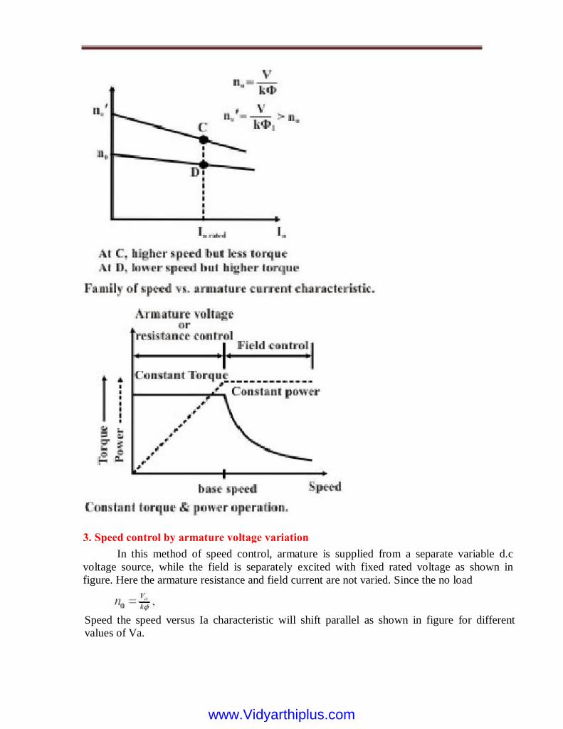
3. Speed control by armature voltage variation
In this method of speed control, armature is supplied from a separate variable d.c
voltage source, while the field is separately excited with fixed rated voltage as shown in
figure. Here the armature resistance and field current are not varied. Since the no load
Speed the speed versus Ia characteristic will shift parallel as shown in figure for different
values of Va.
www.Vidyarthiplus.comwww.Vidyarthiplus.com

As flux remains constant, this method is suitable for constant torque loads. In a way
armature voltage control method is similar to that of armature resistance control method
except that the former one is much superior as no extra power loss takes place in the armature
circuit. Armature voltage control method is adopted for controlling speed from base speed
down to very small speed, as one should not apply across the armature a voltage, which is
higher than the rated voltage.
4. Ward Leonard method: combination of Va and If control
In this scheme, both field and armature control are integrated as shown in figure.
Arrangement for field control is rather simple. One has to simply connect an appropriate
rheostat in the field circuit for this purpose. However, in the pre power electronic era,
obtaining a variable d.c supply was not easy and a separately excited d.c generator was used to
supply the motor armature. Obviously to run this generator, a prime mover is required. A 3-
phase induction motor is used as the prime mover which is supplied from a 3-phase supply.
By controlling the field current of the generator, the generated emf,
www.Vidyarthiplus.comwww.Vidyarthiplus.com
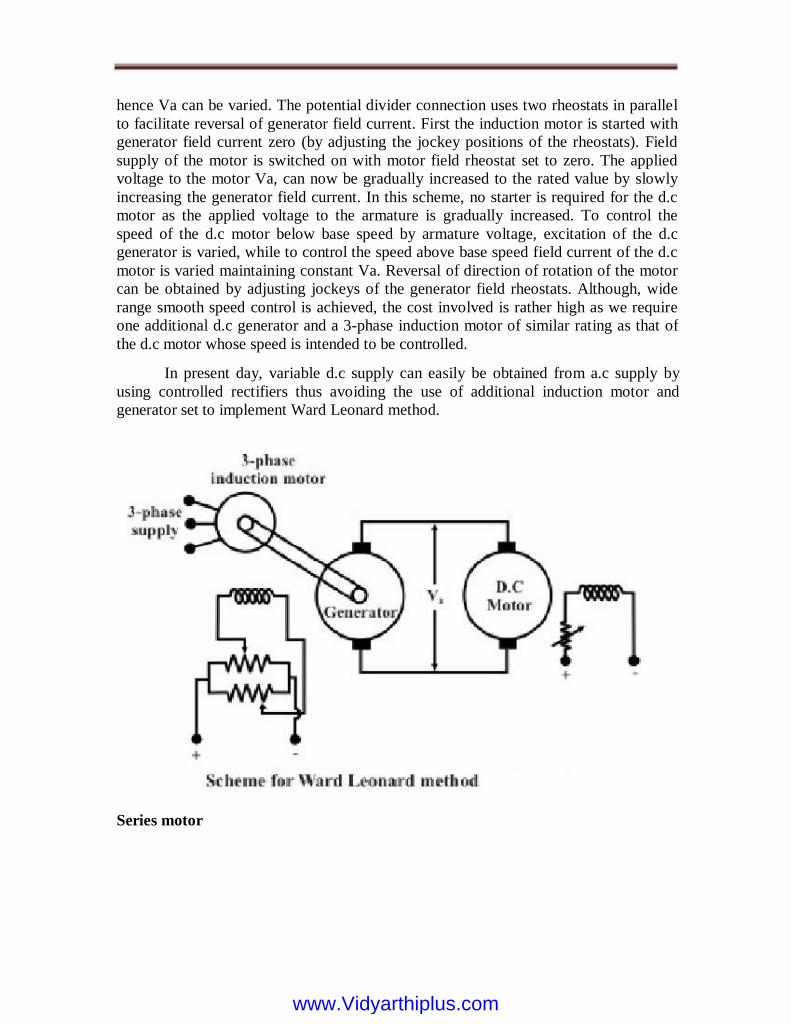
hence Va can be varied. The potential divider connection uses two rheostats in parallel
to facilitate reversal of generator field current. First the induction motor is started with
generator field current zero (by adjusting the jockey positions of the rheostats). Field
supply of the motor is switched on with motor field rheostat set to zero. The applied
voltage to the motor Va, can now be gradually increased to the rated value by slowly
increasing the generator field current. In this scheme, no starter is required for the d.c
motor as the applied voltage to the armature is gradually increased. To control the
speed of the d.c motor below base speed by armature voltage, excitation of the d.c
generator is varied, while to control the speed above base speed field current of the d.c
motor is varied maintaining constant Va. Reversal of direction of rotation of the motor
can be obtained by adjusting jockeys of the generator field rheostats. Although, wide
range smooth speed control is achieved, the cost involved is rather high as we require
one additional d.c generator and a 3-phase induction motor of similar rating as that of
the d.c motor whose speed is intended to be controlled.
In present day, variable d.c supply can easily be obtained from a.c supply by
using controlled rectifiers thus avoiding the use of additional induction motor and
generator set to implement Ward Leonard method.
Series motor
www.Vidyarthiplus.comwww.Vidyarthiplus.com

In this motor the field winding is connected in series with the armature and the
combination is supplied with d.c voltage as depicted in figure 39.13. Unlike a shunt
motor, here field current is not independent of armature current. In fact, field and
armature currents are equal i.e.,
Now torque produced in a d.c motor is:
Torque vs. armature current characteristic
Since in the linear zone and characteristic is as
shown in figure the saturation zone, the T vs. Ia
Speed vs. armature current
From the KVL equation of the motor, the relation between speed and armature current can
be obtained as follows:
1. Characteristics of series motor
Since torque is proportional to the square of the armature current, starting torque of a
series motor is quite high compared to a similarly rated d.c shunt motor. .
www.Vidyarthiplus.comwww.Vidyarthiplus.com

Remember that the value of Ia, is a measure of degree of loading. Therefore, a series
motor should never be operated under no load condition. Unlike a shunt motor, a series motor
has no finite no load speed. Speed versus armature current characteristic is shown in figure
side
The relationship is inverse in nature making speed dangerously high as
www.Vidyarthiplus.comwww.Vidyarthiplus.com
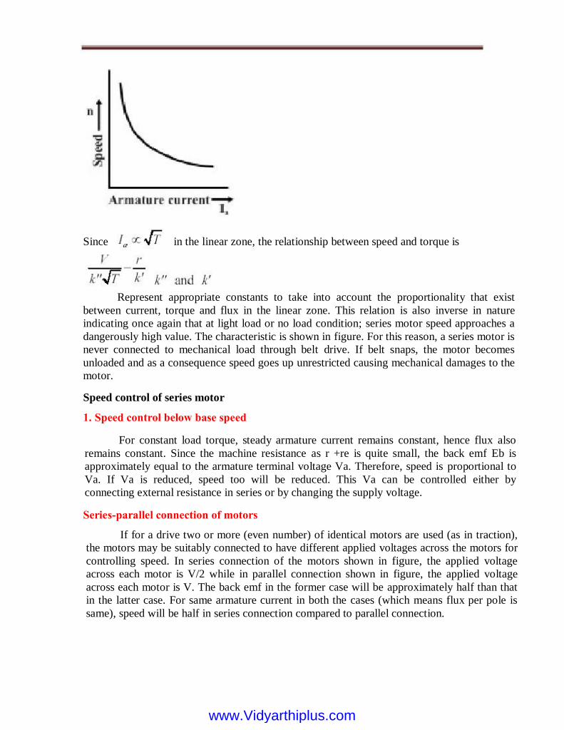
Since in the linear zone, the relationship between speed and torque is
1. Speed control below base speed
For constant load torque, steady armature current remains constant, hence flux also
remains constant. Since the machine resistance as r +re is quite small, the back emf Eb is
approximately equal to the armature terminal voltage Va. Therefore, speed is proportional to
Va. If Va is reduced, speed too will be reduced. This Va can be controlled either by
connecting external resistance in series or by changing the supply voltage.
Series-parallel connection of motors
If for a drive two or more (even number) of identical motors are used (as in traction),
the motors may be suitably connected to have different applied voltages across the motors for
controlling speed. In series connection of the motors shown in figure, the applied voltage
across each motor is V/2 while in parallel connection shown in figure, the applied voltage
across each motor is V. The back emf in the former case will be approximately half than that
in the latter case. For same armature current in both the cases (which means flux per pole is
same), speed will be half in series connection compared to parallel connection.
Speed control of series motor
Represent appropriate constants to take into account the proportionality that exist
between current, torque and flux in the linear zone. This relation is also inverse in nature
indicating once again that at light load or no load condition; series motor speed approaches a
dangerously high value. The characteristic is shown in figure. For this reason, a series motor is
never connected to mechanical load through belt drive. If belt snaps, the motor becomes
unloaded and as a consequence speed goes up unrestricted causing mechanical damages to the
motor.
www.Vidyarthiplus.comwww.Vidyarthiplus.com
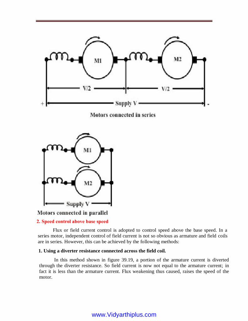
2. Speed control above base speed
Flux or field current control is adopted to control speed above the base speed. In a
series motor, independent control of field current is not so obvious as armature and field coils
are in series. However, this can be achieved by the following methods:
1. Using a diverter resistance connected across the field coil.
In this method shown in figure 39.19, a portion of the armature current is diverted
through the diverter resistance. So field current is now not equal to the armature current; in
fact it is less than the armature current. Flux weakening thus caused, raises the speed of the
motor.
www.Vidyarthiplus.comwww.Vidyarthiplus.com

2. Changing number of turns of field coil provided with tapings.
In this case shown figure 39.20, armature and field currents are same. However
provision is kept to change the number of turns of the field coil. When number of turns
changes, field mmf se f N I changes, changing the flux hence speed of the motor.
3. Connecting field coils wound over each pole in series or in. parallel.
Generally the field terminals of a d.c machine are brought out after connecting the
field coils (wound over each pole) in series. Consider a 4-pole series motor where there will
be 4 individual coils placed over the poles. If the terminals of the individual coils are
www.Vidyarthiplus.comwww.Vidyarthiplus.com
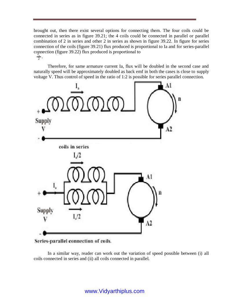
brought out, then there exist several options for connecting them. The four coils could be
connected in series as in figure 39.21; the 4 coils could be connected in parallel or parallel
combination of 2 in series and other 2 in series as shown in figure 39.22. In figure for series
connection of the coils (figure 39.21) flux produced is proportional to Ia and for series-parallel
connection (figure 39.22) flux produced is proportional to
Therefore, for same armature current Ia, flux will be doubled in the second case and
naturally speed will be approximately doubled as back emf in both the cases is close to supply
voltage V. Thus control of speed in the ratio of 1:2 is possible for series parallel connection.
In a similar way, reader can work out the variation of speed possible between (i) all
coils connected in series and (ii) all coils connected in parallel.
www.Vidyarthiplus.comwww.Vidyarthiplus.com
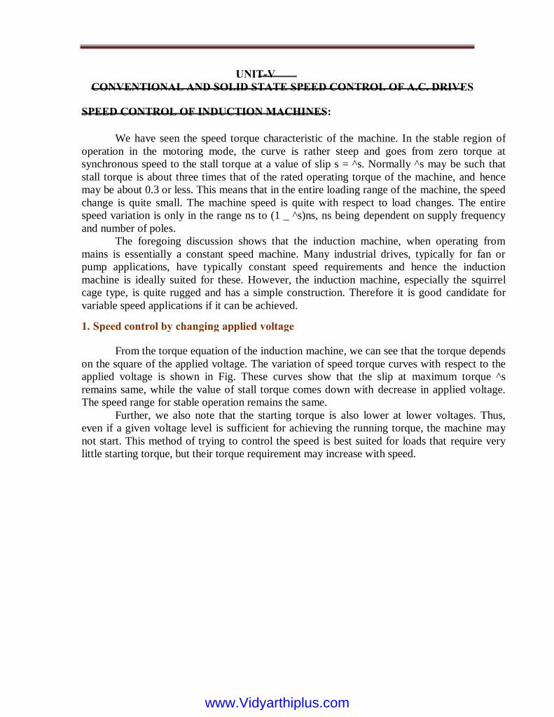
UNIT-V
CONVENTIONAL AND SOLID STATE SPEED CONTROL OF A.C. DRIVES
SPEED CONTROL OF INDUCTION MACHINES:
We have seen the speed torque characteristic of the machine. In the stable region of
operation in the motoring mode, the curve is rather steep and goes from zero torque at
synchronous speed to the stall torque at a value of slip s = ^s. Normally ^s may be such that
stall torque is about three times that of the rated operating torque of the machine, and hence
may be about 0.3 or less. This means that in the entire loading range of the machine, the speed
change is quite small. The machine speed is quite with respect to load changes. The entire
speed variation is only in the range ns to (1 _ ^s)ns, ns being dependent on supply frequency
and number of poles.
The foregoing discussion shows that the induction machine, when operating from
mains is essentially a constant speed machine. Many industrial drives, typically for fan or
pump applications, have typically constant speed requirements and hence the induction
machine is ideally suited for these. However, the induction machine, especially the squirrel
cage type, is quite rugged and has a simple construction. Therefore it is good candidate for
variable speed applications if it can be achieved.
From the torque equation of the induction machine, we can see that the torque depends
on the square of the applied voltage. The variation of speed torque curves with respect to the
applied voltage is shown in Fig. These curves show that the slip at maximum torque ^s
remains same, while the value of stall torque comes down with decrease in applied voltage.
The speed range for stable operation remains the same.
Further, we also note that the starting torque is also lower at lower voltages. Thus,
even if a given voltage level is sufficient for achieving the running torque, the machine may
not start. This method of trying to control the speed is best suited for loads that require very
little starting torque, but their torque requirement may increase with speed.
1. Speed control by changing applied voltage
www.Vidyarthiplus.comwww.Vidyarthiplus.com
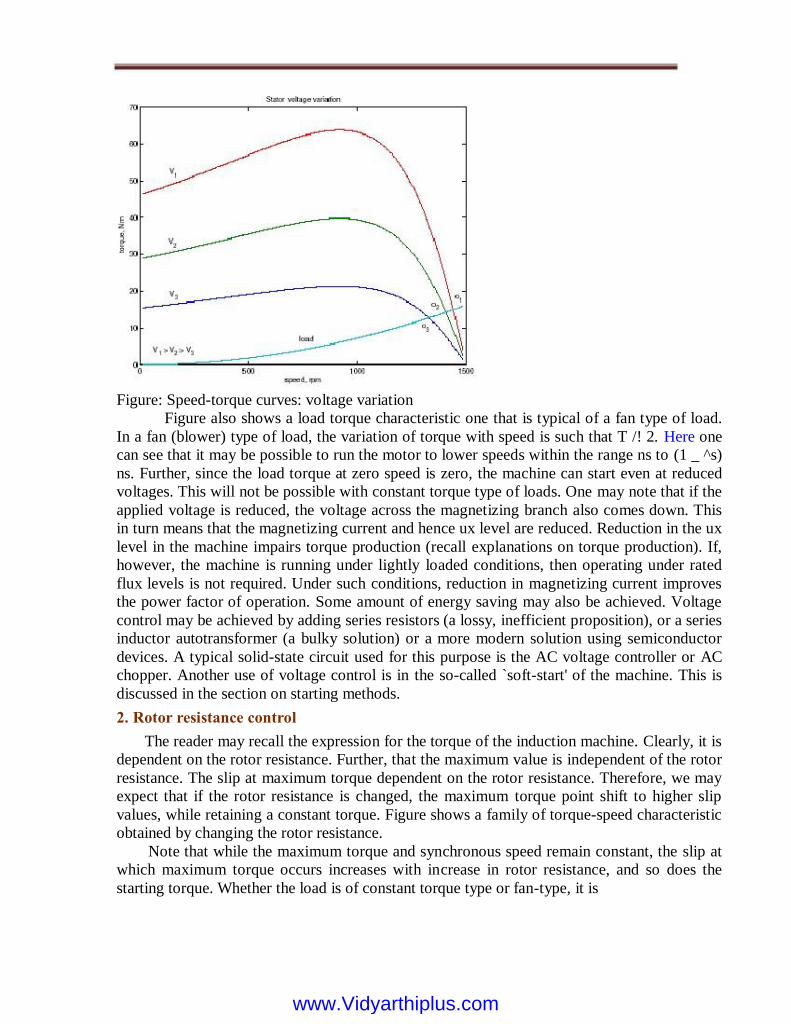
2. Rotor resistance control
The reader may recall the expression for the torque of the induction machine. Clearly, it is
dependent on the rotor resistance. Further, that the maximum value is independent of the rotor
resistance. The slip at maximum torque dependent on the rotor resistance. Therefore, we may
expect that if the rotor resistance is changed, the maximum torque point shift to higher slip
values, while retaining a constant torque. Figure shows a family of torque-speed characteristic
obtained by changing the rotor resistance.
Note that while the maximum torque and synchronous speed remain constant, the slip at
which maximum torque occurs increases with increase in rotor resistance, and so does the
starting torque. Whether the load is of constant torque type or fan-type, it is
Figure: Speed-torque curves: voltage variation
Figure also shows a load torque characteristic one that is typical of a fan type of load.
In a fan (blower) type of load, the variation of torque with speed is such that T /! 2. Here one
can see that it may be possible to run the motor to lower speeds within the range ns to (1 _ ^s)
ns. Further, since the load torque at zero speed is zero, the machine can start even at reduced
voltages. This will not be possible with constant torque type of loads. One may note that if the
applied voltage is reduced, the voltage across the magnetizing branch also comes down. This
in turn means that the magnetizing current and hence ux level are reduced. Reduction in the ux
level in the machine impairs torque production (recall explanations on torque production). If,
however, the machine is running under lightly loaded conditions, then operating under rated
flux levels is not required. Under such conditions, reduction in magnetizing current improves
the power factor of operation. Some amount of energy saving may also be achieved. Voltage
control may be achieved by adding series resistors (a lossy, inefficient proposition), or a series
inductor autotransformer (a bulky solution) or a more modern solution using semiconductor
devices. A typical solid-state circuit used for this purpose is the AC voltage controller or AC
chopper. Another use of voltage control is in the so-called `soft-start' of the machine. This is
discussed in the section on starting methods.
www.Vidyarthiplus.comwww.Vidyarthiplus.com

evident that the speed control range is more with this method. Further, rotor resistance control
could also be used as a means of generating high starting torque.
For all its advantages, the scheme has two serious drawbacks. Firstly, in order to vary the
rotor resistance, it is necessary to connect external variable resistors (winding resistance itself
cannot be changed). This therefore necessitates a slip-ring machine, since only in that case rotor
terminals are available outside. For cage rotor machines, there are no rotor terminals. Secondly,
the method is not very efficient since the additional resistance and operation at high slips entails
dissipation resistors connected to the slip-ring brushes should have good power dissipation
capability. Water based rheostats may be used for this. A `solid-state' alternative to a rheostat is
a chopper controlled resistance where the duty ratio control of the chopper presents a variable
resistance load to the rotor of the induction machine.
The power drawn from the rotor terminals could be spent more usefully. Apart from
using the heat generated in meaning full ways, the slip ring output could be connected to
another induction machine. The stator of the second machine would carry slip frequency
currents of the first machine, which would generate some useful mechanical power. A still
better option would be to mechanically couple the shafts of the two machines together. This
sort of a connection is called cascade connection and it gives some measure of speed control
as shown below.
Let the frequency of supply given to the first machine be f1, its number poles be p1,
and its slip of operation be s1. Let f2; p2 and s2 be the corresponding quantities for the second
machine. The frequency of currents owing in the rotor of the first machine and hence in the
stator of the second machine is s1f1. Therefore f2 = s1f1. Since the machines are coupled at
the shaft, the speed of the rotor is common for both. Hence, if n is the speed of the rotor
3. Cascade control
Figure: Speed-torque curves: rotor resistance variation
www.Vidyarthiplus.comwww.Vidyarthiplus.com

Figure: Generalized rotor control
in radians,
Clearly now, the value of s can be changed by the value of Pr. For Pr = 0, the machine is
like a normal machine with a short circuited rotor. As Pr becomes positive, for all other circuit
conditions remaining constant, s increases or in the other words, speed reduces. As Pr
becomes negative, the right hand side of the equation and hence the slip decreases. The
physical interpretation is that we now have an active source connected on the rotor side, which
is able to supply part of the rotor copper losses. When Pr = _I02 2 R2 the entire copper loss is
supplied by the external source. The RHS and hence the slip is zero. This corresponds to
operation at synchronous speed. In general the circuitry connected to the rotor may not be a
simple resistor or a machine but a power electronic circuit, which can process this power
requirement. This circuit may drive a machine or recover power back to the mains. Such
circuits are called static Kramer drives.
4. Pole changing schemes
The latter expression is for the case where the second machine is connected in opposite
phase sequence to the first. The cascade-connected system can therefore run at two possible
speeds. Speed control through rotor terminals can be considered in a much more general way.
Consider the induction machine equivalent circuit, where the rotor circuit has been terminated
with a voltage source Er.
If the rotor terminals are shorted, it behaves like a normal induction machine. This is
equivalent to saying that across the rotor terminals a voltage source of zero magnitude is
connected. Different situations could then be considered if this voltage source Er had a non-
zero magnitude. Let the power consumed by that source be Pr. Then considering the rotor side
circuit power dissipation per phase
Note that while giving the rotor output of the first machine to the stator of the second,
the resultant stator mmf of the second machine may set up an air-gap flux which rotates in the
same direction as that of the rotor, or opposes it. This results in values for speed as
www.Vidyarthiplus.comwww.Vidyarthiplus.com

In case (b) however, the flux lines are out of the poles in A & C. The flux lines will be
then have to complete the circuit by owing into the pole structures on the sides. If, when seen
from the rotor, the pole emanating flux lines is considered as north pole and the pole into
which they enter is termed as south, then the pole configurations produced by these
connections is a two-pole arrangement in fig and a four-pole arrangement. Thus by changing
the terminal connections we get either a two pole air-gap field or a four- pole field. In an
induction machine this would correspond to a synchronous speed reduction in half from case
(a) to case (b). Further note that irrespective of the connection, the applied voltage is balanced
by the series addition of induced emfs in two coils. Therefore the air-gap flux in both cases is
the same. Cases (a) and (b) therefore form a pair of constant torque connections.
Figure: Pole arrangement
Sometimes induction machines have a special stator winding capable of being
externally connected to form two different number of pole numbers. Since the synchronous
speed of the induction machine is given by ns = fs=p (in rev./s) where p is the number of pole
pairs, this would correspond to changing the synchronous speed. With the slip now
corresponding to the new synchronous speed, the operating speed is changed. This method of
speed control is a stepped variation and generally restricted to two steps.
If the changes in stator winding connections are made so that the air gap flux remains
constant, then at any winding connection, the same maximum torque is achievable. Such
winding arrangements are therefore referred to as constant-torque connections. If however
such connection changes result in air gap flux changes that are inversely proportional to the
synchronous speeds, then such connections are called constant-horsepower type. The
following figure serves to illustrate the basic principle.
Consider a magnetic pole structure consisting of four pole faces A, B, C, D in fig.
Coils are wound on A & C in the directions shown. The two coils on A & C may be connected
in series in two different ways | A2 may be connected to C1 or C2. A1 with the other terminal
at C then form the terminals of the overall combination. Thus two connections result as shown
in fig.
Now, for a given direction of current flow at terminal A1, say into terminal A1, the
flux directions within the poles are shown in the figures. In case (a), the flux lines are out of
the pole A (seen from the rotor) for and into pole C, thus establishing a two-pole structure.
www.Vidyarthiplus.comwww.Vidyarthiplus.com

Consider, on the other hand a connection as shown in the fig. The terminals T1 and T2
are where the input excitation is given. Note that current direction in the coils now resembles
that of case (b), and hence this would result in a four-pole structure. However, in fig, there is
only one coil-induced emf to balance the applied voltage. Therefore flux in case (c) would
therefore be halved compared to that of case (b) (or case(a), for that matter). Cases (a) and (c)
therefore form a pair of constant horse power connections. It is important to note that in
generating a different pole numbers, the current through one coil (out of two, coil C in this
case) is reversed. In the case of a three-phase machine, the following example serves to
explain this. Let the machine have coils connected as shown [C1 _ C6]
The current directions shown in C1 & C2 correspond to the case where T1; T2; T3 are
supplied with three phase excitation and Ta; Tb & Tc are shorted to each other (STAR point).
The applied voltage must be balanced by induced emf in one coil only (C1 & C2 are parallel).
If however the excitation is given to Ta; Tb& Tc with T1; T2; T3 open, then current
through one of the coils (C1 & C2) would reverse. Thus the effective number of poles would
increase, thereby bringing down the speed. The other coils also face similar conditions.
5. Stator frequency control
The expression for the synchronous speed indicates that by changing the stator
frequency also it can be changed. This can be achieved by using power electronic circuits
called inverters, which convert dc to ac of desired frequency. Depending on the type of
www.Vidyarthiplus.comwww.Vidyarthiplus.com

control scheme of the inverter, the ac generated may be variable-frequency-fixed-
amplitude or variable-frequency- variable-amplitude type. Power electronic control
achieves smooth variation of voltage and frequency of the ac output. This when fed to the
machine is capable of running at a controlled speed. However, consider the equation for
the induced emf in the induction machine.
where N is the number of the turns per phase, _m is the peak flux in the air gap and f is the
frequency. Note that in order to reduce the speed, frequency has to be reduced. If the
frequency is reduced while the voltage is kept constant, thereby requiring the amplitude of
induced emf to remain the same, flux has to increase. This is not advisable since the machine
likely to enter deep saturation. If this is to be avoided, then flux level must be maintained
constant which implies that voltage must be reduced along with frequency. The ratio is held
constant in order to maintain the flux level for maximum torque capability.
Actually, it is the voltage across the magnetizing branch of the exact equivalent circuit
that must be maintained constant, for it is that which determines the induced emf. Under
conditions where the stator voltage drop is negligible compared the applied voltage, is valid.
In this mode of operation, the voltage across the magnetizing inductance in the 'exact'
equivalent circuit reduces in amplitude with reduction in frequency and so does the inductive
reactance. This implies that the current through the inductance and the flux in the machine
remains constant. The speed torque characteristics at any frequency may be estimated as
before. There is one curve for every excitation frequency considered corresponding to every
value of synchronous speed. The curves are shown below. It may be seen that the maximum
torque remains constant.
Figure: Pole change example: three phase
www.Vidyarthiplus.comwww.Vidyarthiplus.com

Equation shows that this maximum value is independent of the frequency. Further ^s! is
independent of frequency. This means that the maximum torque always occurs at a speed
lower than synchronous speed by a fixed difference, independent of frequency. The overall
effect is an apparent shift of the torque-speed characteristic as shown in fig. Though this is the
aim, E is an internal voltage, which is not accessible. It is only the terminal voltage V that we
have access to and can control. For a fixed V, E changes with operating slip (rotor branch
impedance changes) and further due to the stator impedance drop. Thus if we approximate E=f
as V=f, the resulting torque-speed characteristic shown in fig. is far from desirable.
If this equation is differentiated with respect to s and equated to zero to find the slip at
maximum torque ^s, we get ^s = _R0 r=(! L0 lr). The maximum torque is obtained by
substituting this value into eqn.
Figure: Torque-speed curves with E=f held constant
This may be seen mathematically as follows. If E is the voltage across the magnetizing branch
and f is the frequency of excitation, then E = kf, where k is the constant of proportionality. If!
= 2_f, the developed torque is given by
www.Vidyarthiplus.comwww.Vidyarthiplus.com

Figure: Torque-speed curves with V=f constant
At low frequencies and hence low voltages the curves show a considerable reduction
in peak torque. At low frequencies (and hence at low voltages) the drop across the stator
impedance prevents sufficient voltage availability. Therefore, in order to maintain sufficient
torque at low frequencies, a voltage more than proportional needs to be given at low speeds.
Another component of compensation that needs to be given is due to operating slip.
With these two components, therefore, the ratio of applied voltage to frequency is not a
constant but is a curve such as that shown in fig. With this kind of control, it is possible to get
a good starting torque and steady state
performance. However, under dynamic conditions, this control is insufficient. Advanced
control techniques such as field- oriented control (vector control) or direct torque control
(DTC) are necessary.
Figure: Voltage boost required for V=f control
www.Vidyarthiplus.comwww.Vidyarthiplus.com

Department of Electrical & Electronics Engineering
Electrical Drives and Control – EE 6351
(For Mechanical Engineering)
Third Semester
2 marks (Questions & Answers)
UNIT – I
INTRODUCTION
1. Define Drive and Electric Drive.
Drive: A combination of prime mover, transmission equipment and mechanical
working load is called a drive Electric drive: An Electric Drive can be defined as an electromechanical device for converting electrical energy to mechanical energy to impart motion to different
machines and mechanisms for various kinds of process control.
I.C Engines, Steam engine, Turbine or electric motors.
4. Give some examples of Electric Drives.
i. ii. iii.
iv.
Driving fans, ventilators, compressors and pumps. Lifting goods by hoists and cranes. Imparting motion to conveyors in factories, mines and warehouses Running excavators & escalators, electric locomotives trains, cars trolley buses, lifts & drum winders etc.
5. What are the types of electric drives?
Group electric drives (Shaft drive), I
iii.
ii.
i. Availability of electric drives over a wide range of power a few
watts to mega watts. Ability to provide a wide range of torques over wide range of speeds. Electric motors are available in a variety of design in order to make them compatible to any type of load.
3. List out some advantages of electric drives.
2. List out some examples of prime movers.
www.Vidyarthiplus.comwww.Vidyarthiplus.com

Individual Drives, Multi motor electric drives.
Classify electric drives based on the means of control. Manual,Semiautomatic, Automatic. 7. What is a Group Electric Drive (Shaft Drive)?
This drive consists of single motor, which drives one or more line shafts supported on bearings. The line shaft may be fitted with either pulleys & belts or gears, by means of which a group of machines or mechanisms may be operated.
6.
Disadvantages:
2. What is an individual electric drive? Give some examples.
In this drive, each individual machine is driven by a separate motor. This motor also imparts motion to various other parts of the machine. Single spindle drilling machine, Lathe machines etc.
3. What is a multi motor electric drive? Give some examples.
In this drive, there are several drives, each of which serves to activate on of the working parts of the driven mechanisms.
There is no flexibility, Addition of an extra machine to the main shaft is difficult. The efficiency of the drive is low, because of the losses occurring in several transmitting mechanisms. The complete drive system requires shutdown if the motor, requires servicing or repair.
The system is not very safe to operate The noise level at the work spot is very high.
Advantages: A single large motor can be used instead of a number of small motors. The rating of the single motor may be appropriately reduced taking into account the diversity factor of loads.
1. What are the advantages and disadvantages of Group drive (Shaft drive)?
www.Vidyarthiplus.comwww.Vidyarthiplus.com
Metal cutting machine tools, paper making machines, rolling mills, traction drive, Traveling cranes etc.,
4. Write about manual control, semiautomatic control & Automatic control?
Manual control: The electric drives with manual control can be as simple as a room fan, incorporating on switch and a resistance for setting the required speed. Semiautomatic control: This control consists of a manual device for giving a certain command (Starting, braking, reversing, change of speed etc.,) and an automatic device that in response to command, operates the drive in accordance with a preset sequence or order.
Automatic control: The electric drives with automatic control have a control gear, without manual devices
Power Supply
Motor
Geared Coupling
Mechanical Laod
A load diagram is the diagram which shows graphically the variation of torque acting on the electric drive. The motor of the electric drive has to overcome the load torque expressed as a function of time.
Types:
One for the static or steady state process Other for the dynamic process, when the dynamic components of torque are induced by the inertia of the motor & load. (Instantaneous speed, acceleration, Torque & power) as a function of time are required to draw…..
14. What are the types Drive systems?
13. What is a load diagram? What are its types? What are required to draw a load diagram?
Speed & Torque Control
12. What are the Typical elements of an Electric Drive?
www.Vidyarthiplus.comwww.Vidyarthiplus.com

Electric Drives Electromechanical Drives
Mechanical Drives Hydraulic drives.
15. Give an expression for the losses occurring in a machine.
The losses occurring in a machine is given by W = Wc + x2 Wv Where Wc = Constant losses Wv = Variable losses at full load X = load on the motor expressed as a function of rated load.
ii.
iii.
17. What are the factors that influence the choice of electrical drives? 1. Shaft power & speed11. Speed range 2. Power range12. Efficiency 3. Starting torque13.Influence on the supply network 4. Maintenance14. Special competence 5. Total purchase cost15. Cost of energy losses 6. Influence on power supply16. Environment 7. Availability17. Accessibility 8. Nature of electric supply18. Nature of load 9. Types of drive19. Electrical Characteristics 10.Service cost20. Service capacity & rating
18. Indicate the importance of power rating & heating of electric drives.
Power rating: Correct selection of power rating of electric motor is of economic interest as it is associated with capital cost and running cost of drives. Heating: For proper selection of power rating the most important consideration is the heating effect
i. The machine is considered to be a homogeneous body having a uniform temperature gradient. All the points at which heat generated have the same temperature. All the points at which heat is dissipated are also at same temperature. Heat dissipation taking place is proportional to the difference of temperature of the body and surrounding medium. No heat is radiated. The rate of dissipation of heat is constant at all temperatures.
16. What are the assumptions made while performing heating & cooling calculation of an electric motor?
www.Vidyarthiplus.comwww.Vidyarthiplus.com

of load. In this connection various forms of loading or duty cycles have to be considered.
19. How heating occurs in motor drives?
The heating of motor due to losses occurring inside the motor while converting the electrical power into mechanical power and these losses occur in steel core, motor winding & bearing friction.
20. What are the classes of duties? 1. Continuous duty 2. Short time duty operation of motor Main classes of duties 3. Intermittent periodic duty 4. Intermittent periodic duty with starting 5. Intermittent periodic duty with starting & braking 6. Continuous duty with intermittent periodic loading 7. Continuous duty with starting & braking 8. Continuous duty with periodic load changes
23. Why the losses at starting is not a factor of consideration in a continuous duty motor? While selecting a motor for this type of duty it is not necessary to give importance to the heating caused by losses at starting even though they are more than the losses at rated load. This is because the motor does not require frequent starting it is started only once in its duty cycle and the losses during starting do not have much influence on heating.
What is meant by “short time rating of motor”? Any electric motor that is rated for a power rating P for continuous operation can be loaded for a short time duty (Psh) that is much higher than P, if the temperature rise is the consideration.
24.
22. List out some applications for which continuous duty is required. Centrifugal pumps, fans, conveyors & compressors
1. 2. 3. 4. 5. 6.
Reversible &non reversible in controlled constant speed Reversible and non reversible step speed control Reversible and non reversible smooth speed control Constant predetermined position control Variable position control Composite control.
21. How will you classify electric drives based on the method of speed control?
www.Vidyarthiplus.comwww.Vidyarthiplus.com

What is meant by “load equalization”? In the method of “load Equalization” intentionally the motor inertia is increased by adding a flywheel on the motor shaft, if the motor is not to be reversed. For effectiveness of the flywheel, the motor should have a prominent drooping characteristic so that on load there is a considerable speed drop.
26. How a motor variable load ? 1. Method of 2. Method of 3. Method of 4. Method of
rating is determined in a continuous duty and
Average losses equivalent power equivalent current equivalent Torque
25.
27. Draw the heating & cooling curve of an electric motor.
29. Write down the heat balance equation. Heat balance equation is given by Ghd0 + S0 .dt = p.dt
28. What are the various function performed by an electric drive?
1. Driving fans, ventilators, compressors & pumps etc., 2. Lifting goods by hoists & cranes 3. Imparting motion to conveyors in factories, mines & warehouses and 4. Running excavators & escalators, electric locomotives, trains, cars, trolley buses and lifts etc.
www.Vidyarthiplus.comwww.Vidyarthiplus.com

UNIT – II ELECTRICAL MOTOR CHARACTERISTICS
1. Why a single phase induction motor does not self start?
When a single phase supply is fed to the single phase induction motor. Its stator winding produces a flux which only alternates along one space axis. It is not a synchronously revolving field, as in the case of a 2 or 3phase stator winding, fed from 2 or 3 phase supply.
2. What is meant by plugging?
The N-T curve moves towards the right when the voltage is increased. This can be achieved by means of additional resistance in the armature circuit or by using thyristor power converter.
6. Compare electrical and mechanical braking.
Mechanical Brakes require frequent maintenance Not smooth Can be applied to hold the system at any position torque.
Electrical very little maintenance smooth cannot produce holding
5. What is the effect of variation of armature voltage on N-T curve and how it can be achieved?
Dynamic or Rheostatic braking, Counter current or plugging and Regenerative braking
4. What are the different types of electric braking?
Shunt : driving constant speed, lathes, centrifugal pumps, machine tools, blowers and fans, reciprocating pumps Series : electric locomotives, rapid transit systems, trolley cars, cranes and hoists, conveyors Compound : elevators, air compressors, rolling mills, heavy planners.
3. Give some applications of DC motor.
The plugging operation can be achieved by changing the polarity of the motor there by reversing the direction of rotation of the motor. This can be achieved in ac motors by changing the phase sequence and in dc motors by changing the polarity.
www.Vidyarthiplus.comwww.Vidyarthiplus.com

7. When does an induction motor behave to run off as a generator?
When the rotor of an induction motor runs faster than the stator field, the slip becomes negative. Regenerative braking occurs and the K.E. of the rotating parts is return back to the supply as electrical energy and thus the machine generates power.
8. Define slip.
S = Ns – Nr Ns Where, Ns Nr S
9. Define synchronous speed.
In the regenerative braking operation, the motor operates as a generator, while it is still connected to the supply here, the motor speed is grater that the synchronous speed. Mechanical energy is converter into electrical energy, part of which is returned to the supply and rest as heat in the winding and bearing.
6. Give some applications of DC motor.
Shunt: driving constant speed, lathes, centrifugal pumps, machine tools, blowers and fans, reciprocating pumps Series: electric locomotives, rapid transit systems, trolley cars, cranes and hoists, conveyors Compound: elevators, air compressors, rolling mills, heavy planners.
5. What is meant by regenerative braking?
When a single phase supply is fed to the single phase induction motor. Its stator winding produces a flux which only alternates along one space axis. It is not a synchronously revolving field, as in the case of a 2 or 3phase stator winding, fed from 2 or 3 phase supply.
10. Why a single phase induction motor does not self start?
It is given by Ns = 120f / p rpm. WhereNs = synchronous speed, p = no. of stator poles, f = supply frequency in Hz
= synchronous speed in rpm. = rotor speed in rpm = Slip
www.Vidyarthiplus.comwww.Vidyarthiplus.com

7. Compare electrical and mechanical braking.
Mechanical Brakes require frequent maintenance Not smooth Can be applied to hold the system at any position torque.
Electrical very little maintenance smooth cannot produce holding
8. Differentiate cumulative and differential compound motors.
Cumulative The orientation of the series flux aids the shunt flux shunt flux
9. What is meant by mechanical characteristics?
A curve drawn between the parameters speed and torque.
differential series flux opposes
2. Mention the Starters used to start an Induction motor.
D.O.L Starter (Direct Online Starter) Star-Delta Starter Auto Transformer Starter Reactance or Resistance starter Stator Rotor Starter (Rotor Resistance Starter)
3. What are the protective devices in a DC/AC motor Starter.
Over load Release (O.L.R) or No volt coil Hold on Coil Thermal Relays Fuses(Starting /Running) Over load relay
Two point Starter Three point Starter Four point Starter
1. Mention the Starters used to start a DC motor.
UNIT – III
STARTING METHODS
www.Vidyarthiplus.comwww.Vidyarthiplus.com
4. Is it possible to include/ Exclude external resistance in the rotor of a Squirrel cage induction motor?. Justify
No it is not possible to include/ Exclude external resistance in the rotor of a Squirrel cage induction motor because, the rotors bars are permanently short circuited by means of circuiting rings (end rings) at both the ends. i.e. no slip rings to do so.
5. Give the prime purpose of a starter for motors.
when induction motor is switched on to the supply, it takes about 5 to 8 times full load current at starting. This starting current may be of such a magnitude as to cause objectionable voltage drop in the lines. So Starters are necessary
6. Why motor take heavy current at starting?
To include resistance in the rotor circuit there by reducing the induced rotor current at starting. This can be implemented only on a slip ring induction motor.
9. Why squirrel cage induction motors are not used for loads requiring high starting torque?
Squirrel cage motors are started only by reduced voltage starting methods which leads to the development of low starting torque at starting. This is the reason Why squirrel cage induction motors are not used for loads requiring high starting torque.
10. How reduced voltage starting of Induction motor is achived?.
8. What is the objective of rotor resistance starter (stator rotor starter)?
7. What are the methods to reduce the magnitude of rotor current (rotor induced current) at starting?. By increasing the resistance in the rotor circuit By reducing the magnitude of rotating magnetic field i.e by reducing the applied voltage to the stator windings.
Since rotor of an induction motor behaves as a short circuited secondary of a transformer whose primary is stator winding, heavy rotor current will require corresponding heavy stator balancing currents. Thus motor draws heavy current at starting
When 3 phase supply is given to the stator of an induction motor, magnetic field rotating in space at synchronous speed is produced. This magnetic field is cut by the rotor conductors, which are short circuited. This gives to induced current in them.
www.Vidyarthiplus.comwww.Vidyarthiplus.com
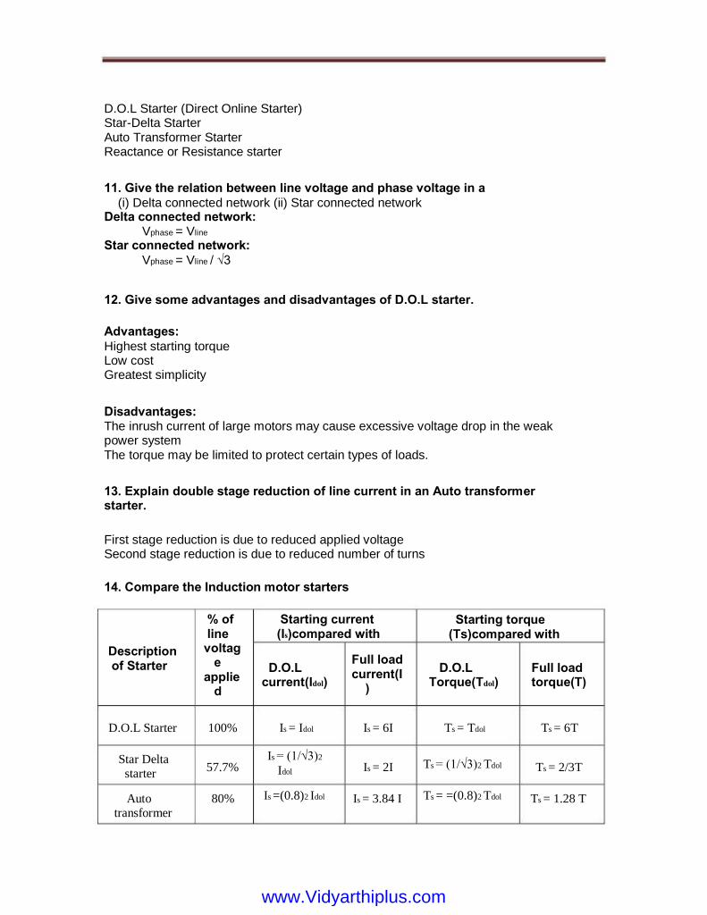
D.O.L Starter (Direct Online Starter) Star-Delta Starter Auto Transformer Starter Reactance or Resistance starter
11. Give the relation between line voltage and phase voltage in a (i) Delta connected network (ii) Star connected network Delta connected network: Vphase = Vline Star connected network: Vphase = Vline / √3
14. Compare the Induction motor starters
% of line voltag e applie d
100%
57.7%
80%
Starting current (Is)compared with
D.O.L current(Idol)
Is = Idol
Is = (1/√3)2 Idol
Is =(0.8)2 Idol
Full load current(I )
Is = 6I
Is = 2I
Is = 3.84 I
Starting torque (Ts)compared with
D.O.L Torque(Tdol)
Ts = Tdol
Ts = (1/√3)2 Tdol
Ts = =(0.8)2 Tdol
Full load torque(T)
Ts = 6T
Ts = 2/3T
Ts = 1.28 T
Description of Starter
D.O.L Starter
Star Delta starter
Auto transformer
First stage reduction is due to reduced applied voltage Second stage reduction is due to reduced number of turns
13. Explain double stage reduction of line current in an Auto transformer starter.
Disadvantages: The inrush current of large motors may cause excessive voltage drop in the weak power system The torque may be limited to protect certain types of loads.
Advantages: Highest starting torque Low cost Greatest simplicity
12. Give some advantages and disadvantages of D.O.L starter.
www.Vidyarthiplus.comwww.Vidyarthiplus.com
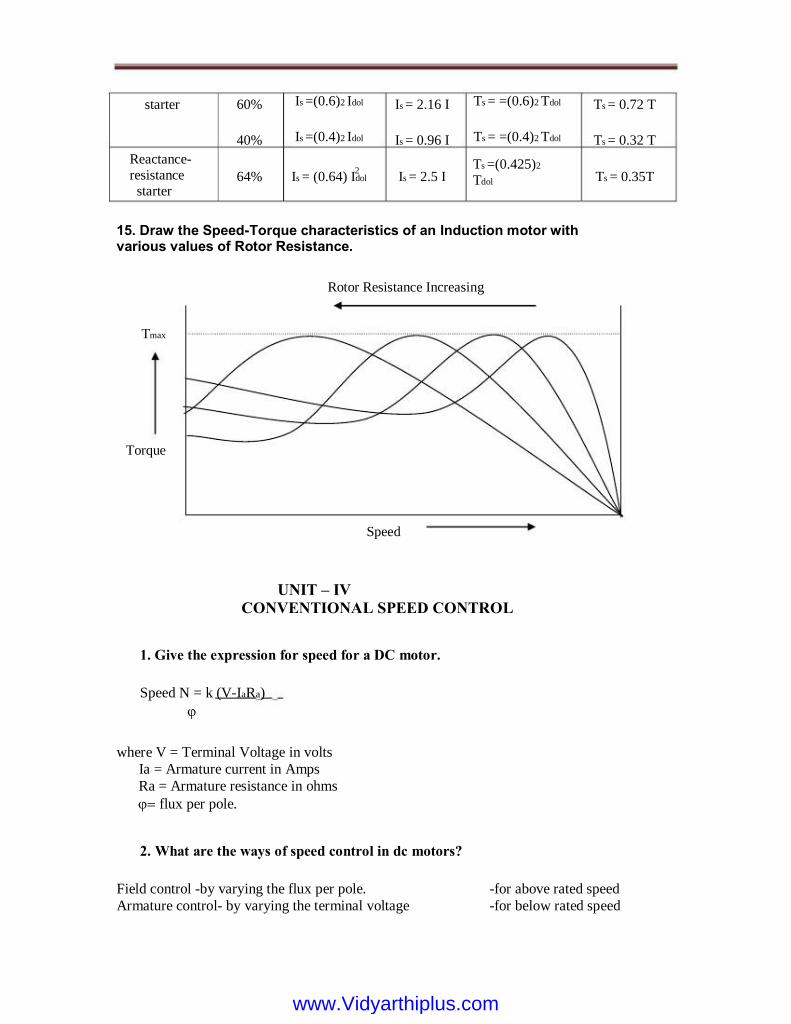
starter 60%
40%
Reactance- resistance starter
64%
Is =(0.6)2 Idol
Is =(0.4)2 Idol
Is = (0.64) Idol 2
Is = 2.16 I
Is = 0.96 I
Is = 2.5 I
Ts = =(0.6)2 Tdol
Ts = =(0.4)2 Tdol
Ts =(0.425)2 Tdol
Ts = 0.72 T
Ts = 0.32 T
Ts = 0.35T
15. Draw the Speed-Torque characteristics of an Induction motor with various values of Rotor Resistance.
Rotor Resistance Increasing
Torque
Speed N = k (V-IaRa)
where V = Terminal Voltage in volts Ia = Armature current in Amps Ra = Armature resistance in ohms flux per pole.
2. What are the ways of speed control in dc motors?
Field control -by varying the flux per pole. Armature control- by varying the terminal voltage
-for above rated speed -for below rated speed
1. Give the expression for speed for a DC motor.
UNIT – IV
CONVENTIONAL SPEED CONTROL
Speed
Tmax
www.Vidyarthiplus.comwww.Vidyarthiplus.com
3. Give the Limitation of field control
a. Speed lower than the rated speed cannot be obtained. b. It can cope with constant kW drives only. c. This control is not suitable to application needing speed reversal.
4. Compensating winding can be used to increase the speed range in field control method
5. What are the 3 ways of field control in DC series motor?
6. What are the main applications of Ward-Leonard system?
7. What are the merits and demerits of rheostat control method?
Impossible to keep the speed constant on rapidly changing loads.
A large amount of power is wasted in the controller resistance.
Loss of power is directly proportional to the reduction in speed. Hence
efficiency is decreased. Maximum power developed is diminished in the same ratio as speed. It needs expensive arrangements for dissipation of heat produced in the controller resistance. It gives speed below normal, not above.
8. What are the advantages of field control method?
More economical, more efficient and convenient.
It is used for colliery winders. Electric excavators In elevators Main drives in steel mills and blooming and paper mills.
Field diverter control Armature diverter control Motor diverter control Field coil taps control Series-parallel control
www.Vidyarthiplus.comwww.Vidyarthiplus.com

It can give speeds above normal speed.
9. Compare the values of speed and torque in case of motors when in parallel and in series.
The speed is one fourth the speed of the motor when in parallel.
The torque is four times that produced by the motor when in parallel.
10. Mention the speed control method employed in electric traction.
Series-parallel speed control.
11. What is the effect of inserting resistance in the field circuit of a dc shunt motor on its speed and torque?
Applied voltage should be maintained constant so as to maintain field strength
12. While controlling the speed of a dc shunt motor what should be done to achieve a constant torque drive?
For a constant supply voltage, flux will decrease, speed will increase and torque will increase.
www.Vidyarthiplus.comwww.Vidyarthiplus.com
UNIT – V
SOLID STATE SPEED CONTROL
1. What is a controlled rectifier?
A controlled rectifier is a device which is used for converting controlled dc power from a control voltage ac supply.
2. What is firing angle?
The control of dc voltage is achieved by firing the thyristor at an adjustable angle with respect to the applied voltage. This angle is known as firing angle.
3. Give some applications of phase control converters.
4. What is the main purpose of free wheeling diode?
6. What is natural or line commutation?
The commutation which occurs without any action of external force is called natural or line commutation.
7. What is forced commutation?
The commutation process which takes place by the action of an external force is called forced commutation.
8. What is a chopper?
A chopper is essentially an electronic switch that turns on the fixed-voltage dc source for a short time intervals and applies the source potential to motor terminals in series of pulses.
A full converter is a tow quadrant converter in which the voltage polarity of the output can reverse, but the current remains unidirectional because of unidirectional thyristors.
5. What is a full converter?
Free wheeling diode is connected across the motor terminal to allow for the dissipation of energy stored in motor inductance and to provide for continuity of motor current when the thyristors are blocked.
Phase control converters are used in the speed control of fractional kW dc motors as well as in large motors employed in variable speed reversing drives for rolling mills. with motors ratings as large as several MW‟s.
.
www.Vidyarthiplus.comwww.Vidyarthiplus.com

9. What are the two main difficulties of variable frequency system?
Control of Va requires variation of chopper frequency over a wide range. Filter design for variable frequency operation is difficult.
10. At low voltage, a large value of toff makes the motor current discontinuous.
Classify commutation.
Voltage commutation
Current commutation.
12. What is current commutation?
13. What is load commutation?
14. What are the different means of controlling induction motor?
15. What are the two ways of controlling the RMS value of stator voltage?
16. Mention the two slip-power recovery schemes.
Stator voltage control.
Frequency control
Pole changing control.
Slip power recovery control.
Phase control
Integral cycle control
The load current flowing through the thyristor either becomes zero (as in natural or line commutation employed in converters) or is transferred to another device from the conducting thyristor. This is known as load commutation.
A current pulse is forced in the reverse direction through the conducting thyristor. As the net current becomes zero, the thyristor is turned OFF. This is known as current commutation.
A charged capacitor momentarily reverse-bias the conducting thyristor to turn it off. This is known as voltage commutation.
11. What is voltage commutation?
www.Vidyarthiplus.comwww.Vidyarthiplus.com

Static Kramer drive scheme. 17. Give the basic difference between the two slip-power recovery schemes.
The slip is returned to the supply network in scherbius scheme and in Kramer scheme, it is used to drive an auxiliary motor which is mechanically coupled to the induction motor shaft.
18. Write short notes on inverter rectifier.
The dc source could be converted to ac form by an inverter, transformed to a suitable voltage and then rectified to dc form. Because of two stage of conversion, the setup is bulky, costly and less efficient.
Static scherbius scheme
What is electrical power supply system?
The generation, transmission and distribution system of electrical power is called electrical power supply system.
21. What are the 4 main parts of distribution system?
Feeders,
Distributors and
Service mains.
22. What are feeders?
Since a static Kramer system possesses no line commutated inverter, it causes less reactive power and smaller harmonic contents of current than a static scherbius.
20. What are the advantages of static Kramer system,, over static scherbius system?
This drive provides a constant torque control.
If max. slip is denoted by S max, then power rating of diode, inverter and
transformer can be just Smax times motor power rating resulting in a low cost drive.
The scheme has applications in large power fan and pump drives which requires
speed control in anrrow range only.
19. Give the special features of static scherbius scheme.
www.Vidyarthiplus.comwww.Vidyarthiplus.com

Feeders are conductors which connect the stations (in some cases generating stations) to the areas to be fed by those stations.
23. What are the advantages of high voltage dc system over high voltage ac system?
It requires only tow conductors for transmission and it is also possible to transmit the power through only one conductor by using earth as returning conductor, hence much copper is saved.
No inductance, capacitance, phase displacement and surge problem.
There is no skin effect in dc, cross section of line conductor is fully utilized.
24. What do you mean by the term earthing?
25. What are the different methods of providing neutral earthing?
Reactance earthing
Arc suppression coil or Peterson coil earthing.
Resistance earthing
Solid earthing
The term “earthing” means connecting the non-current carrying parts of electrical equipment to the neutral point of the supply system to the general mass of earth in such a manner that at all time an immediate discharge of electrical energy takes place without danger.
www.Vidyarthiplus.comwww.Vidyarthiplus.com