ee19d digital electronics - uwi st. augustine · • ics are classified depending of the type of...
TRANSCRIPT

1
EE19D Digital Electronics
Lecture 1: General Introduction

2
What are we going to discuss?• Some Definitions• Digital and Analog Quantities• Binary Digits, Logic Levels and Digital Waveforms• Introduction to logic Operations• Fixed-Function Integrated Circuits• Programmable Logic: Introduction• Design Methods for Digital systems

3
1. Some Definitions
• What is engineering?– Purposeful use of science
• What is Digital Electronics?
Use of electrical circuits to process and transform information. Here Information are seen as discrete values (“0” or “1”)

4
5
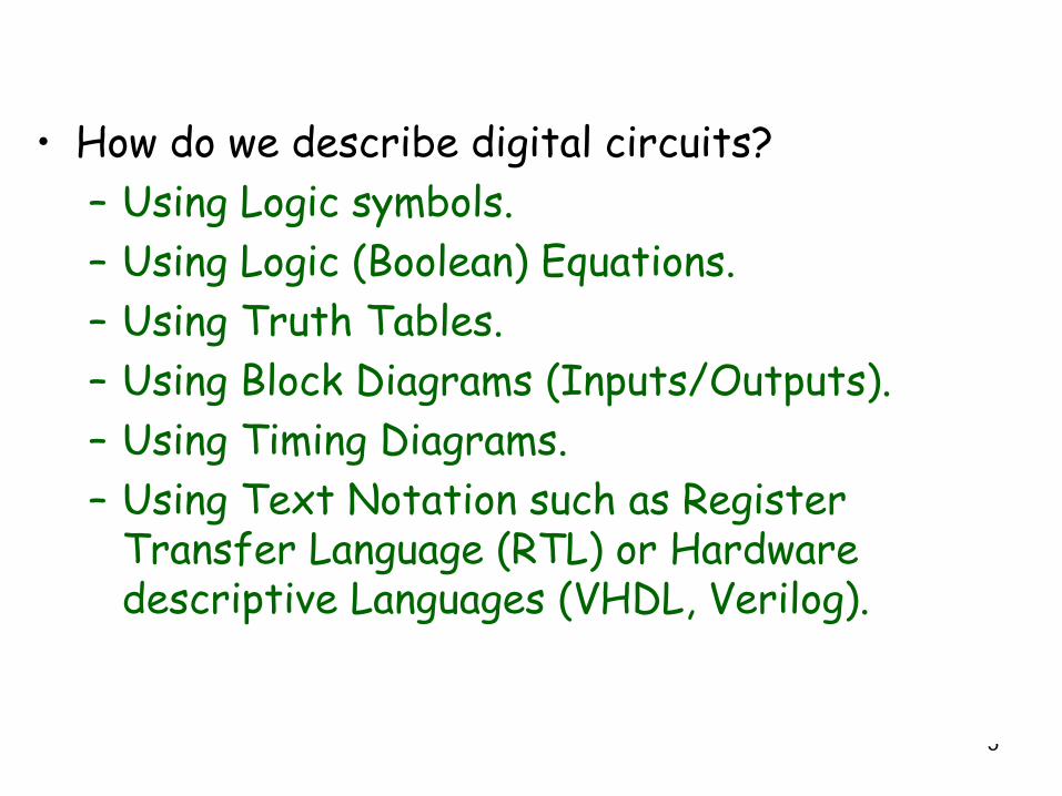
• How do we describe digital circuits?– Using Logic symbols.– Using Logic (Boolean) Equations.– Using Truth Tables.– Using Block Diagrams (Inputs/Outputs).– Using Timing Diagrams.– Using Text Notation such as Register
Transfer Language (RTL) or Hardware descriptive Languages (VHDL, Verilog).

6
2. Digital and Analog Quantities• Electronics circuits can be divided in three broad categories, digital, analog, and
mixed analog-digital.• Digital electronics deals with signals that represent discrete values, analog
electronics involves continuous values. In practice the majority of electronic systems are mixed analog-digital systems. In these systems, digital electronics is used for processing/presentation, while analog electronics for amplification/transmission
• Quiz: Imagine the scenario of a phone call using a cellular phone. Sketch its analog and digital functionalities.
• How do we see the physical word? – Our physical word is analog. For example, the air temperature changes over
a continuous value range of values, that are quantify with numbers.– A weather station unit is used to monitor physical parameters such as
pressure, wind speed, humidity, etc. These physical parameters are sensed by special sensors (converter of physical quantity to voltage or current).
– We quantify these physical parameters with numbers, which can berepresented as discrete values and then converted to a digital representation form ( binary, decimal, octal, hexadecimal).

7
Observation of the Physical World

8
2. Digital and Analog Quantities (cont’d)
• The following is a graph of air temperature vs time (figure 1)
• By considering the temperature every hour we will have sampled values (discrete points as shown in figure 2). Each sample can be represented in a particular digital code.
• The process of analog to digital conversion consists of sampling, quantization and coding (Signal processing). A particular circuit called ADC can do the job for you. For digital to analog conversion, we can use a DAC.
• Quiz: Sketch a block diagram that shows different functional modules of and ADC. Imagine the use of operational amplifiers.
Figure 1: Graph of an analog quantity (temperature versus time
Figure 2: sampled-value representation of the analog value of fig. 1.

9
2. Digital and Analog Quantities (cont’d)• Digital Advantages
– Digital data can be processed and transmitted more efficiently and reliably than analog data.
– Digital data has a great advantage when storage is necessary. For example, music when converted to digital form can be stored more compactly and reproduced with greater accuracy and clarity than is possible when it is in analog form.
– Digital representation used in image processing opens new opportunities that are impossible in analog such as compression, encryption/decryption, and synthesis.
• Example of a mixed analog-digital system: The CD Player (Figure 3).
• Examples of once-analog systems that have now “gone digital”:
– Still image picture systems now digital cameras– Video Recoding (DVD: digital versatile disc)– Audio recording (CD: digital compact disc)– Telephone system (PABX: private automatic
branch exchange)– Traffic light controllers
Figure 3: Basic principle of a CD player

10
• Other Reasons to favor digital circuits over analog ones:– Reproductibility of results– Easy of design (for simple circuits)– Flexibility and functionality– Programmability– Speed– Steadily and advancing technology.
11
3. Binary Digits, Logic levels and Digital waveforms• Digital electronics involves circuits and systems in which there are
only two possible states. A complete electronic definition of each of these states requires voltage and current levels, power consumption, and time propagation.
• A definition using voltage levels is sufficient enough to understand the theory: High and low.
• Quiz: For voltage levels how can we quantify High and low voltages? Image the representation of the two possible states using current levels? Why it’s preferable to use voltage levels?
• But for practical design, one has to consider other parameters (technology).
• In digital systems such as computers, these two systems can combined in a particular way to define codes, that are used to represent numbers, symbol, alphabetic characters or other types of information.
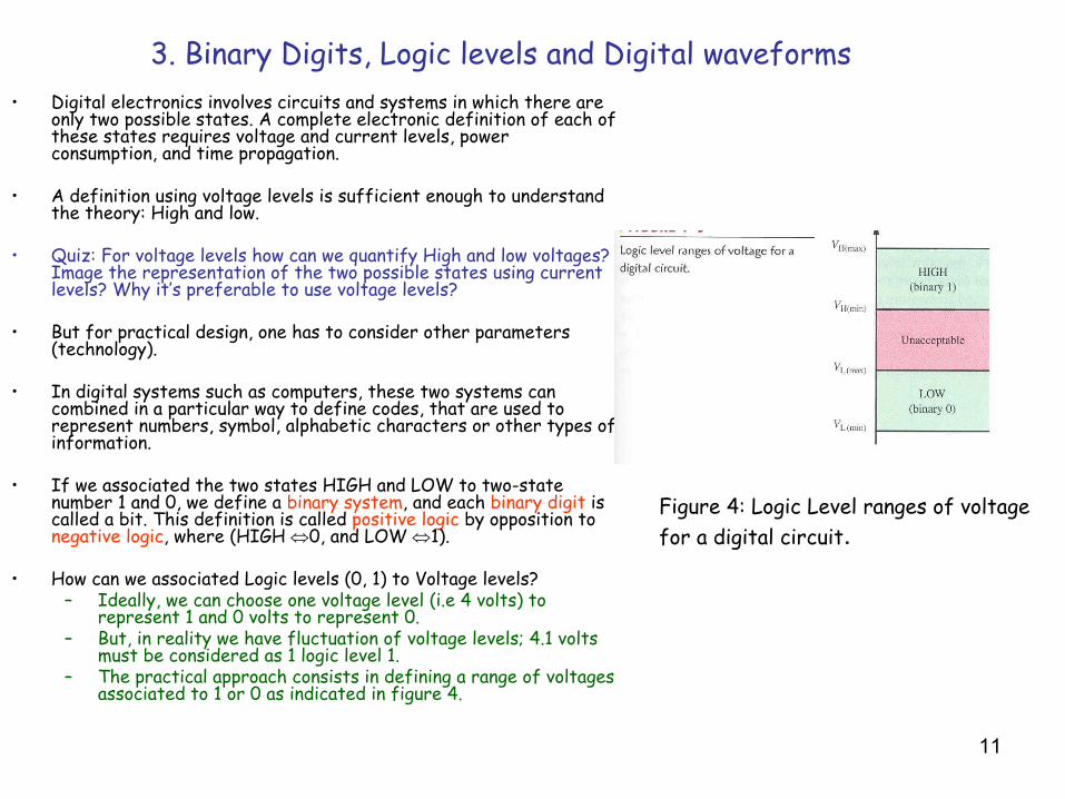
• If we associated the two states HIGH and LOW to two-state number 1 and 0, we define a binary system, and each binary digit is called a bit. This definition is called positive logic by opposition to negative logic, where (HIGH ⇔0, and LOW ⇔1).
• How can we associated Logic levels (0, 1) to Voltage levels? – Ideally, we can choose one voltage level (i.e 4 volts) to
represent 1 and 0 volts to represent 0.– But, in reality we have fluctuation of voltage levels; 4.1 volts
must be considered as 1 logic level 1.– The practical approach consists in defining a range of voltages
associated to 1 or 0 as indicated in figure 4.
Figure 4: Logic Level ranges of voltage for a digital circuit.
12
3. Binary Digits, Logic levels and Digital waveforms (cont’d)
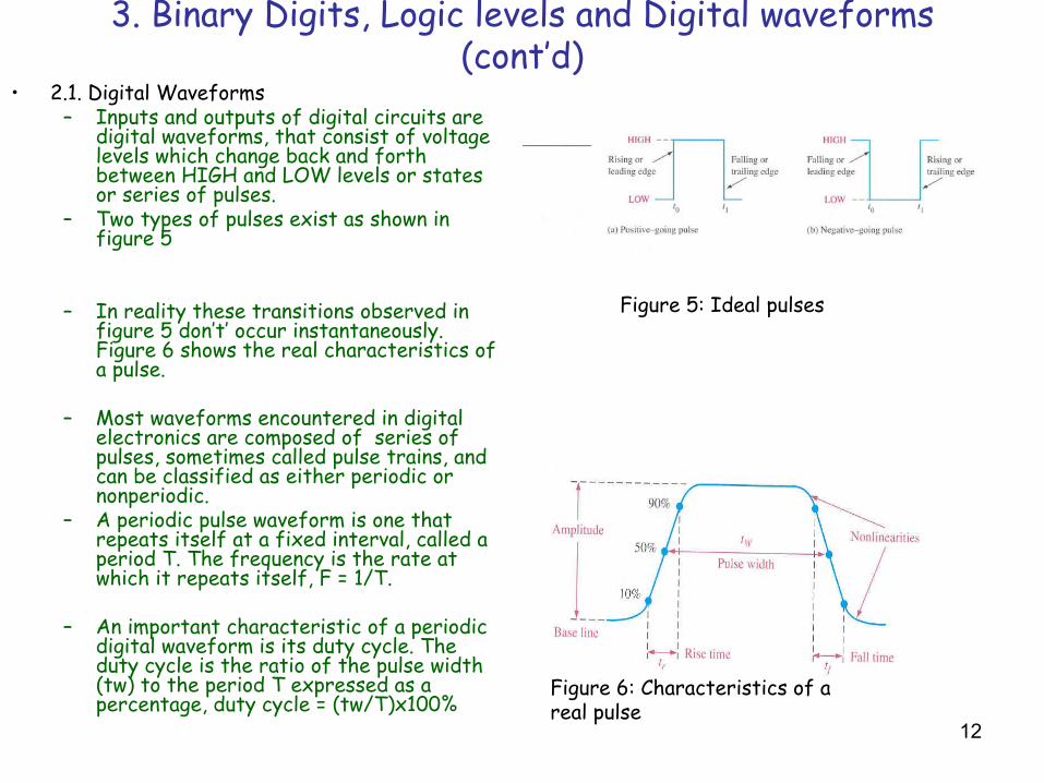
• 2.1. Digital Waveforms– Inputs and outputs of digital circuits are
digital waveforms, that consist of voltage levels which change back and forth between HIGH and LOW levels or states or series of pulses.
– Two types of pulses exist as shown in figure 5
– In reality these transitions observed in figure 5 don’t’ occur instantaneously. Figure 6 shows the real characteristics of a pulse.
– Most waveforms encountered in digital electronics are composed of series of pulses, sometimes called pulse trains, and can be classified as either periodic or nonperiodic.
– A periodic pulse waveform is one that repeats itself at a fixed interval, called a period T. The frequency is the rate at which it repeats itself, F = 1/T.
– An important characteristic of a periodic digital waveform is its duty cycle. The duty cycle is the ratio of the pulse width (tw) to the period T expressed as a percentage, duty cycle = (tw/T)x100%
Figure 5: Ideal pulses
Figure 6: Characteristics of a real pulse

13
4. Introduction to logic Operations
• In digital logic we identify three major operators: OR, NOT, and AND.
• Other operators derive from the combination of these three.
• Each logic operator is characterized by a logic diagram (logic gate representation), and a truth table that is associated to Boolean algebra. The following figure shows different logic gates (figure 7).
• These basic logic gates are use to build combinational circuits, whose outputs at any time can be expressed as Boolean functions of inputs.
Figure 7: Major Logic Gates

14
4. Introduction to logic Operations (cont’d)• Other type of circuits encountered in digital electronics are
Sequential circuits.• A sequential circuit is a circuit in which decisions are made
based on combinations of the current inputs as well as the past history of the outputs.
• For the design of sequential circuits, there is a need to use circuit with a memory behavior, in which the outputs depends upon their previous states and inputs. A basic memory element iscalled a latch.
• Just as gates are fundamental units of combinational logic, elementary memory units called SR latches (S: set, R: reset) arealso for sequential networks. More complex memory elements are called flip-flops.

15
5. Basic Overview of Logic Functions
• The comparison Function• The arithmetic functions (addition, subtraction, multiplication
and division)• The code conversion function• The encoding function• The data selection function (multiplexing)• The data storage functions: latchs, flip-flops, registers,
semiconductor memories• The counting function

16
Multiplexing - demultiplexing
17
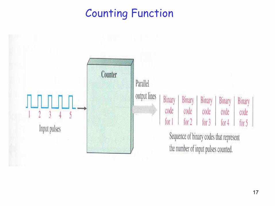
Counting Function

18
6. Example of a digital system: Block diagram of a tablet-counting and bottling control system.

19
7. Fixed-function integrated circuit
• The logic gates and functions that we have presented are available as integrated circuits (ICs)
• ICs are classified depending of the type of packaging, function (fixed or programmable), and level of integration.
• A monolithic integrated circuit is an electronic circuit that isconstructed on a single small chip of silicon (wafer). Figure 8 shows a cutaway view of one type of fixed-function IC package.
•
Figure 8: Cutaway view of one of fixed-function IC package.

20
• Integrated circuit (IC) package are classified according to the way there are mounted on printed circuit (PC) boards as either through-hole mounted or surface mounted. The most common type of through-hole package is the dual in-line package DIP as shown in figure 9.
Figure 9: Examples of Through-hole and surface-mounted devices

21
• Four common types of SMT (surface-mount technology) packages are the SOIC (small-outline IC), the PLCC (plastic leaded chip carrier), the LCCC (leadless ceramic chip carrier), and the flat pack (FP). Figure 10 gives an overview.
Figure 10: Examples of SMT package configuration
22
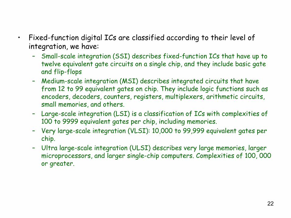
• Fixed-function digital ICs are classified according to their level of integration, we have:– Small-scale integration (SSI) describes fixed-function ICs that have up to
twelve equivalent gate circuits on a single chip, and they include basic gate and flip-flops
– Medium-scale integration (MSI) describes integrated circuits that have from 12 to 99 equivalent gates on chip. They include logic functions such as encoders, decoders, counters, registers, multiplexers, arithmetic circuits, small memories, and others.
– Large-scale integration (LSI) is a classification of ICs with complexities of 100 to 9999 equivalent gates per chip, including memories.
– Very large-scale integration (VLSI): 10,000 to 99,999 equivalent gates per chip.
– Ultra large-scale integration (ULSI) describes very large memories, larger microprocessors, and larger single-chip computers. Complexities of 100, 000 or greater.

23
8. Programmable Logic• Another class of ICs is one in which the logic function is programmable
by the user and, in some cases reprogrammable many times. They are called programmable logic devices (PLDs) or programmable application-specific integrated circuits (ASICs).
• We can identify two categories: simple PLDs and CPLDs/FPGAs• Simple PLDs consist of:
– PAL (programmable array logic)– GAL (generic array logic)– PLA (programmable logic array)– PROM (programmable read-only memory)
• CPLD = Complex programmable logic device• FPGA = Field-programmable gate array• The complete development of digital circuits using these devices
requires:– Hardware descriptive languages (VHDL or Verilog)– Electronic Programmers for physical configuration

24
9. Design Methods used in Digital Electronics
• During this last decade, the electronic industry has witnessed atremendous growth.
• More and more there is an increasing need concerning the design of complex digital systems.
• A simple digital clock doesn’t have the same complexity as an ATM switch.
• What are the methods available today?– Old method (heuristic) or try-and-modify approach– Simulation and prototyping – Use of Hardware descriptive languages / Software-to-
hardware language plus simulation/rapid prototyping
• The selection of a particular method of design is mainly due to the type and the complexity of the circuit.

25
Design Process
Required product
Design specifications
Initial design
Simulation
Design correct?
Redesign
Prototype implementation
Testing
Meets specifications?
Finished product
Minor errors?
Make corrections
No
Yes
No
Yes
Yes
No
26
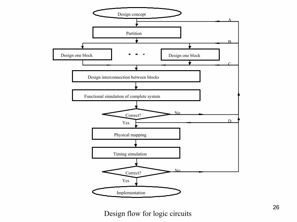
Design interconnection between blocks
Functional simulation of complete system
Correct?
Physical mapping
Timing simulation
Correct?
Implementation
No
Yes
No
Yes
Design one block Design one block
Partition
Design conceptA
B
C
D
Design flow for logic circuits

27
Heuristic Method
• This is one the oldest method of designing electronic circuits.• It was used intensity during the fifties when no computer-aided design
tool was available.• It requires from the designer a good knowledge of electronic
components and concepts (data sheet, major functions in electronics, different IC technologies, and levels of integration).
• Today, it is still been used for designing simple circuits that have less than 100 components.
• It can be summarized in the following steps:– Analysis and drawing of the circuit– Implementation of a prototype on a breadboard (try-and-modify
principle)– Testing and realization of the printed circuit

28
Use of CAD Tools
• Digital circuits are become more complex, the heuristic method cannot be used anymore.
• There are different types of CAD Tools. We can enumerate them asfollows:– CAD for schematic capture, simulation and PCB design: ORCAD,
Workbench, Protel, etc.. Each one of these tools has a Pspicesimulator.
– CAD for behavioral simulation such as Digitalworks.– Hardware Descriptive Language (HDL) Tools: VHDL and Verilog
Compiler.– Complete HDL tools with simulation and synthesis for programmable
devices (Xilinx, Altera, Synopsis, etc…).– Software-to-Hardware tools (Handel-C, System-C, Jbits, etc).
CAD = “ Computer-Aided Design”
29
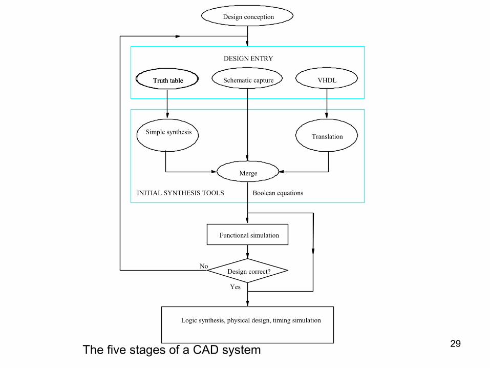
Design conception
Truth table Truth table VHDLSchematic capture
Simple synthesisTranslation
Merge
Boolean equations INITIAL SYNTHESIS TOOLS
DESIGN ENTRY
Design correct?
Logic synthesis, physical design, timing simulation
Functional simulation
No
Yes
The five stages of a CAD system

30
Case Study: Design problem
• Imagine the design of digital clock with a display module.• Write its complete specification.• Design it using the heuristic method.• Show how you can speed up the design process using CAD tools.
At the end of the Semester you should be able to solve this design problem. Just be patient!
31
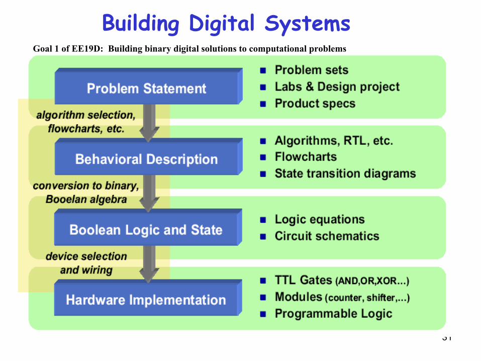
Building Digital SystemsGoal 1 of EE19D: Building binary digital solutions to computational problems

32
Building Digital Systems with HDLs
33
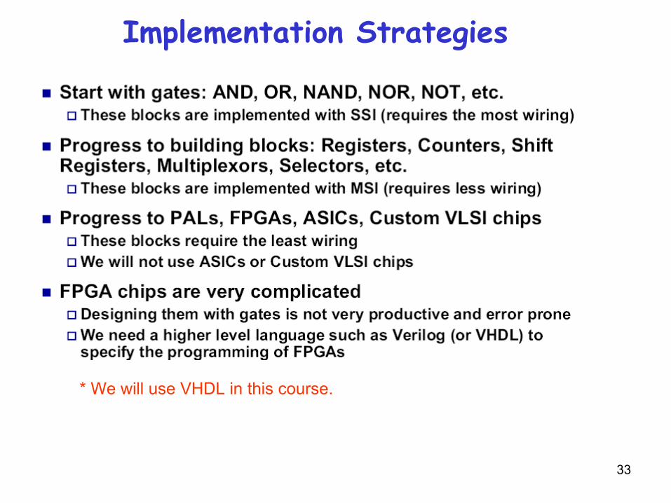
Implementation Strategies
* We will use VHDL in this course.

34
Real-World Performance Metrics