ee776 - tecnologica s.r.l. | rifasamento - strumentazione ... · the ee776 flow meter has a modular...
TRANSCRIPT

130 v2.3 / Modification rights reserved
The EE776 flow meter is based on the thermal mass flow measurement and is ideal for measuring the flow of com-pressed air and gases in pipes from DN50 (2”) to DN700 (28”).With the EE776, the consumption of compressed air, nitro-gen, CO2 or other non-corrosive and non-flammable gases can be measured up to a pressure of 16 bar (232 PSI), for example.
Patented non-return protection for secure mountingThe EE776 flow meter set new standards in terms of safety and easy assembly. The patented non-return protec-tion combines three functions in one device:• Non-return protection
The sensor can only be pushed in one direction dur-ing installation. The sensor cannot return at all, even if it is released.
• Seal By means of an encapsulated O-ring, no compressed air can escape under pressure during assembly.
• Precise positioning The precise positioning with respect to immersion depth and orientation is easy to perform, guarantee-ing accurate measurement results.
The high measurement accuracy of 1.5% from reading results from the application-oriented factory adjustments, which are undertaken at 9 bar (130 PSI) pressure. For opti-mum adaptation to different measurement tasks, you can choose between two measuring ranges 0.2...100 Nm/s (40...19685 SFPM) or 0.2...200 Nm/s (40...39370 SFPM) and three different probe lengths with a maximum immersion depth of 165 mm (6.5”) / 315 mm (12.4”) / 465 mm (18.3”).The inner diameter of the distribution pipe which is measured can be entered via the USB port and the included configuration software.
Two signal outputs are available to output the measured values. Depending on the application, these can be configured as an analogue output (current or voltage), switching output or pulse output for consumption measuring.
Bus interface for Modbus RTU or M-BusOptionally, the flow meter is available with an additional bus interface for MODBUS RTU or M-BUS (Meter-Bus).
EE776
EE776 Insertion Flowmeter for compressed air and gases DN50 - DN700 (2” - 28”)
Measurement of consumption of compressed airCompressed air counterMass flow measurement of industrial gases
Typical Applications FeaturesNon-return protection for secure mounting
Assembly/disassembly under pressure without flow interruption
easy and accurate positioninghigh accuracy ± 1.5% of reading
factory adjustment under pressurePipe diameters DN50 (2”) to DN700 (28”)
Pressure range up to 16 bar (232 PSI)
Wide measuring range up to 200 Nm/s (39370 SFPM)
Bus interface for Modbus RTU or M-Bus
EE776
detailflow sensor

131v2.3 / Modification rights reserved
With the right accessories, the EE776 flow meter can be easily integrated into any measurement task.An assembly without welding and drilling into the pressurised supply line with-out flow interruption, can be implemented very easily with the tapping sleeve.An optional ½“ ball valve on the tapping sleeve enables the installation and removal of the sensor without interrupting the flow in the compressed air line.The ball valve on the tapping sleeve closes the measuring point pressure-tight after removing the flow meter. Regular calibration, without taking into account the device downtime, is therefore always an option.
EE776
DesignThe EE776 flow meter has a modular design and consists of probes (1) and evaluation electronics (2). The probe includes sensor and measuring electronics, in which the factory adjustment data is stored. The evalu-ation electronics communicates digitally with the probe and can be located up to 10 m (32.8 ft) from the probe.
21
Assembly
Flow sensor
Non-return protection
mounting grip
probe cable
evaluation unit
max. 10m (32.8 ft)
Tapping sleeve
Measurement of consumption (totalizer)The EE776 holds an integrated counter for the usage. The amount is stored and the data will not be lost due to a power outage. The availability of the consumption amount as a free configurable pulse output is another helpful feature.
Configuration softwareThe EE776 flowmeter can be configured conveniently, to meet the requirements of the application with the standard configuration soft-ware and the integrated USB interface.
Functionality:• Configuration of the output (scale / set point)• Setting the pipe diameter• 2-point user calibration for flow and temperature• Readout of the counter values• Reset of min / max values and counter• Indication of the measurement value• Configuration of the bus interface

132 v2.3 / Modification rights reserved EE776
Dimensions in mm (inch)115 (4.53“)
60 (2
.36“
)56
(2.2
“)
EE776Enclosure - signal conditioning unit
EE776Sensor probe
EE776Assembly - insertion depth
R 1/2“ thread
USB-Interface
insertion depth = x +
OD... Outside diameter
M12x1 Connector for probe cable
285
(11.
22“) /
435
(17.
13“)
/ 58
5 (2
3.03
“)
OD0.
5 *
OD
x
varia
ble
inse
rtion
dep
thm
ax. 1
65 (6
.5“) /
315
(12.
4“) /
465
(18.
3“)
45 (1
.77“
)
38 (1
.5“)
20 (0
.79“
)
15(0
.59“
)12
(0.4
7“)
120
(4.7
2“)
180 (7.09“)
Ø 40 (1.57“)
Ø 13 (0.51“)
Ø 14 (0.55“)
Ø 40 (1.57“)
SW 36 (1.42“)
OD2
Marking flow direction
flow direction
see accessories for NPT adapter
16 (0.63)
14 (0.55)
19 (0.75)
19 (0.75)
20 (0.79)
NP
T1/2“
SW
24R
p 1/2“
Ø 15 (0.59)
Dimensions accessories in mm (inch)
HA074004Adapter BSP - NPT
25 (0.98)
11 (0.43)
G1/2
G3/4
Ø 26.7 (1.05)
Ø 18.6 (0.73)
HA074001Welding nipple
Material: stainless steel 1.4301
Material: brass

133v2.3 / Modification rights reservedEE776
Connection Diagram
≅Vcc
OUT 1-2
mA_Input+15V
Modbus data B / M-Bus
Modbus data A / M-Bus
OUT 1-1OUT 2-1OUT 2-2
GND18...30V AC/DC
VmA
567891011121314
P
I 4...20mA
Signal-Output
Pressure sensor input
Bus-Interface
Supply voltage
1) With analogue output OUT 1-1 is connected with GND.Switching and pulse output are potential-free.
Material: stainless steel 1.4301
Material: brass
Material: brass
70 (2.76)
82.5 (3.25)
G3/4“
51.5 (2.03)
Ø 15(0.6)
Ø 15(0.6)
G1/2“
HA074002Ball valve 1/2“
HA074003Ball valve 1/2“ for parallel measurement
HA074xxxTapping sleeve (delivery without ball valve)
70 (2.76)
82.5 (3.25)
Lateral fitting Rp1/4“ for mounting of pressure or dew point sensor
G3/4“
54 (2.13)54.5 (2.15)
G1/2“
185
(7.2
8)
∼115
(4.5
3)
22 (0
.87) 11
(0.4
3)
25 (0.98)rubber sealingNBR 70 Shore ball valve HA074002
125 (4.92)
G3/4“
pipe clamping range [mm (inch)]
max. working pressure
DN50 (2“) 47 - 67 (1.85 - 2.64) 16bar (232psi)
DN65 (2 1/2“) 73 - 93 (2.87 - 3.66) 16bar (232psi)
DN80 (3“) 86 - 106 (3.39 - 4.17) 16bar (232psi)
DN100 (4“) 107 - 127 (4.21 - 5.00) 16bar (232psi)
DN125 (5“) 128 - 148 (5.04 - 5.83) 16bar (232psi)
DN150 (6“) 149 - 171 (5.87 - 6.73) 16bar (232psi)
DN200 (8“) 216 - 236 (8.50 - 9.29) 16bar (232psi)
DN250 (10“) 260 - 280 (10.24 - 11.02) 10bar (145psi)
DN300 (12“) 315 - 335 (12.40 - 13.19) 10bar (145psi)
Threaded nipple
Analogue- 1) or switching output
Switching or pulse output
134 v2.3 / Modification rights reserved EE776
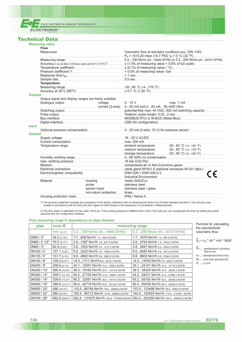
Measuring value Flow Measurand Volumetric flow at standard conditions acc. DIN 1343 P0 = 1013.25 mbar (14.7 PSI); t0 = 0 °C (32 °F) Measuring range 0.2...100 Nm/s (40...19685 SFPM) or 0.2...200 Nm/s (40...39370 SFPM) Accuracy in air at 9bar (130.5psi) (abs) and 23°C (73°F)1) ± (1.5% of measuring value + 0.8% of full scale) Temperature coefficient ± (0.1% of measuring value / °C) Pressure coefficient 2) + 0.5% of measuring value / bar Response time t90 < 1 sec. Sample rate 0.5 sec. Temperature Measuring range -20...80 °C (-4...176 °F) Accuracy at 20°C (68°F) ± 0.7 °C (1.26 °F)Outputs Output signal and display ranges are freely scalable Analogue output voltage 0 - 10 V max. 1 mA current (3-wire) 0 - 20 mA and 4 - 20 mA RL<500 Ohm Switching output potential-free max. 44 VDC, 500 mA switching capacity Pulse output Totalizer, pulse length: 0.02...2 sec. Bus interface MODBUS RTU or M-BUS (Meter-Bus) Digital interface USB (for configuration)Input Optional pressure compensation 4 - 20 mA (2-wire; 15 V) for pressure sensorGeneral
Supply voltage 18 - 30 V AC/DCCurrent consumption max. 200 mATemperature range ambient temperature: -20...60 °C (-4...140 °F) medium temperature: -20...80 °C (-4...176 °F) storage temperature: -20...60 °C (-4...140 °F)Humidity working range 0...99 %RH no condensationmax. working pressure 16 bar (232 Psi)Medium compressed air or Non-Corrosive gasesElectrical connection cable gland M16x1.5 (optional connector M12x1 8pol.)Electromagnetic compatibility EN61326-1 EN61326-2-3 Industrial EnvironmentMaterial housing metal (AlSi3Cu) probe stainless steel sensor head stainless steel / glass non-return protection brassHousing protection class IP65 / Nema 4
1) The accuracy statement includes the uncertainty of the factory calibration with an enhancement factor k=2 (2-times standard deviation). The accuracy was culated in accordance with EA-4/02 and with regard to GUM (Guide to the Expression of Uncertainty in Measurement).
2) The flow meter is calibrated at 9 bar (abs) 130.5 psi. If the working pressure is different from 9 bar (130.5 psi) you can compensate the error by setting the actual pressure with the configuration software.
Flow measuring range in dependence on pipe diameter
Technical Data
pipe inner Ø measuring range mm (inch) 0.2...100 Nm/s (40...19685 SFPM) 0.2...200 Nm/s (40...39370 SFPM)
DN50 / 2“ 54.5 (2.15“) 1.7...839 Nm3/h 1.0...493.8 SCFM 1.7...1679 Nm3/h 1.0...987.6 SCFM
DN65 / 2 1/2“ 70.3 (2.77“) 2.8...1397 Nm3/h 1.6...821.6 SCFM 2.8...2793 Nm3/h 1.6...1643.2 SCFM
DN80 / 3“ 82.5 (3.25“) 3.8...1923 Nm3/h 2.3...1131.5 SCFM 3.8...3847 Nm3/h 2.3...2263.0 SCFM
DN100 / 4“ 107.1 (4.22“) 6.5...3242 Nm3/h 3.8...1906.9 SCFM 6.5...6483 Nm3/h 3.8...3813.8 SCFM
DN125 / 5“ 131.7 (5.19“) 9.8...4902 Nm3/h 5.8...2883.5 SCFM 9.8...9803 Nm3/h 5.8...5766.9 SCFM
DN150 / 6“ 159.3 (6.27“) 14.3...7171 Nm3/h 8.4...4218.7 SCFM 14.3...14343 Nm3/h 8.4...8437.3 SCFM
DN200 / 8“ 206.5 (8.13“) 24.1...12051 Nm3/h 14.2...7089.0 SCFM 24.1...24101 Nm3/h 14.2...14178.0 SCFM
DN250 / 10“ 260.4 (10.25“) 38.3...19163 Nm3/h 22.5...11272.6 SCFM 38.3...38325 Nm3/h 22.5...22545.3 SCFM
DN300 / 12“ 309.7 (12.19“) 54.2...27105 Nm3/h 31.9...15945.1 SCFM 54.2...54211 Nm3/h 31.9...31890.1 SCFM
DN350 / 14“ 339.6 (13.37“) 65.2...32591 Nm3/h 38.3...19172.5 SCFM 65.2...65183 Nm3/h 38.3...38345.0 SCFM
DN400 / 16“ 388.8 (15.31“) 85,4...42719 Nm3/h 50.3...25130.2 SCFM 85.4...85438 Nm3/h 50.3...50260.0 SCFM
DN500 / 20“ 486 (19.13“) 133,5...66749 Nm3/h 78,5...39266.0 SCFM 133.5...133498 Nm3/h 78,5...78531.9 SCFM
DN600 / 24“ 585 (23.03“) 193,4...96712 Nm3/h 113.8...56892.6 SCFM 193.4...193425 Nm3/h 113.8...113785.1 SCFM
DN700 / 28“ 682.6 (26.87“) 263,4...131675 Nm3/h 154.9...77459.8 SCFM 263.4...263350 Nm3/h 154.9...154919.6 SCFM
Formula for calculating the standardized volumetric flow:
V0 = v0 * id2 * π/4 * 3600
V0 ... standardized volumetric flow [m3/h]v0 ... standardized flow [m/s]id ... inner pipe diameter [m]π ... 3.1415

135v2.3 / Modification rights reserved
Position 1 - Flow meter EE776-
Har
dwar
e C
onfig
urat
ion
Model remote probe CWorking range low 0.2...100 Nm/s (40...19685 SFPM) L1
high 0.2...200 Nm/s (40...39370 SFPM) H2pipe diameter / probe lenth
DN50 (2“) / 165 mm (6.5“) N050DN65 (2 1/2“) / 165 mm (6.5“) N065DN80 (3“) / 165 mm (6.5“) N080DN100 (4“) / 165 mm (6.5“) N100DN125 (5“) / 315 mm (12.4“) N125DN150 (6“) / 315 mm (12.4“) N150DN200 (8“) / 315 mm (12.4“) N200DN250 (10“) / 315 mm (12.4“) N250DN300 (12“) / 315 mm (12.4“) N300DN350 (14“) / 465 mm (18.3“) N350DN400 (16“) / 465 mm (18.3“) N400DN500 (20“) / 465 mm (18.3“) N500DN600 (24“) / 465 mm (18.3“) N600DN700 (28“) / 465 mm (18.3“) N700
Display without Display xwith Display D
Electrical connection cable gland M16x1.5 A1 plug M12x1 for power supply and outputs Q
Bus-Interface without bus-interface xModbus RTU 1M-Bus (Meter-Bus) 5
Softw
are
Con
figur
atio
n
Physical parameters of Temperature T [°C] [°F] Bouput 1 standardized volumetric flow V‘0 [Nm3/h] [SCFM] R
mass flow m‘ [kg/h] Sstandardized flow v0 [Nm/s] [ft/min] T
Physical parameters of Temperature T [°C] [°F] Boutput 2 standardized volumetric flow V‘0 [Nm3/h] [SCFM] R
mass flow m‘ [kg/h] Sstandardized flow v0 [Nm/s] [ft/min] Tconsumption 1) Q0 [Nm3] [ft3] I
Output 1 0-5 V 20-10 V 3
analogue output 0-20 mA 54-20 mA 6
switching output SOutput 2 switching ouput S
pulse output 1) IMeasured value unit metric / SI M
non metric US / GB NMedium air A
nitrogen BCO2 Chelium Fargon G
Position 2 - probe cablecable length 2 m HA010816
5 m HA01081710 m HA010818
1) consumption measuring is possible only with pulse output (output 2 = I)
EE776
EE776-CL1N100xAx/RI6IMA Model: remote probeWorking range: 0.2...100 Nm/spipe diameter - probe length: DN100 / 165 mmDisplay: without DisplayEl. connection: cable glandBus-Interface: without bus-interfacePhys. parameter output 1: standardized volumetric flowPhys. parameter output 2: consumptionOutput 1: 4-20mAOutput 2: pulse outputMeasured value unit: metric SIMedium: air
HA010816probe cable 2m
Order Example
Accessories
Position 1 - Flow meter Position 2 - probe cable
tapping sleeve DN50 (2“) HA074050 welding nipple HA074001tapping sleeve DN65 (2 1/2“) HA074065 ball valve 1/2“ HA074002tapping sleeve DN80 (3“) HA074080 ball valve 1/2“ for parallel measurement HA074003tapping sleeve DN100 (4“) HA074100 adapter Rp1/2“ IT to NPT 1/2“ ET HA074004tapping sleeve DN125 (5“) HA074125tapping sleeve DN150 (6“) HA074150tapping sleeve DN200 (8“) HA074200 Dew point sensor see data sheet EE371tapping sleeve DN250 (10“) HA074250 Sampling cell for dew point sensor HA050102tapping sleeve DN300 (12“) HA074300 Quick coupling G1/4“ ET HA070203
Ordering Guide