eecs150 - digital designcs150/fa13/agenda/lec/lec05-verilog_s… · fall 2013 eecs150 -...
TRANSCRIPT
9/10/2013
1
1 Fall 2013 EECS150 - Lec05-verilog_synth Page
EECS150 - Digital Design
Lecture 5 - Verilog Logic Synthesis
Sep. 11, 2013
Prof. Ronald Fearing
Electrical Engineering and Computer Sciences
University of California, Berkeley
(slides courtesy of Prof. John Wawrzynek)
http://www-inst.eecs.berkeley.edu/~cs150
2 Fall 2013 EECS150 - Lec05-verilog_synth Page
Outline
• Quick review of essentials of state
elements
• Finite State Machines in Verilog
• More on Verilog
• Logic Synthesis
2
9/10/2013
2
3 Fall 2013 EECS150 lec04-seq_logic Page
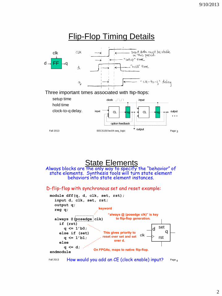
Flip-Flop Timing Details
Three important times associated with flip-flops:
setup time
hold time
clock-to-q delay.
FF
clk
d q
4 Fall 2013 EECS150 - Lec05-verilog_synth Page
State Elements Always blocks are the only way to specify the “behavior” of
state elements. Synthesis tools will turn state element behaviors into state element instances.
module dff(q, d, clk, set, rst);
input d, clk, set, rst;
output q;
reg q;
always @(posedge clk)
if (rst)
q <= 1’b0;
else if (set)
q <= 1’b1;
else
q <= d;
endmodule
D-flip-flop with synchronous set and reset example:
How would you add an CE (clock enable) input?
keyword
“always @ (posedge clk)” is key
to flip-flop generation.
This gives priority to
reset over set and set
over d.
On FPGAs, maps to native flip-flop.
d s
q
r clk
set
rst
9/10/2013
3
5 Fall 2013 EECS150 - Lec05-verilog_synth Page
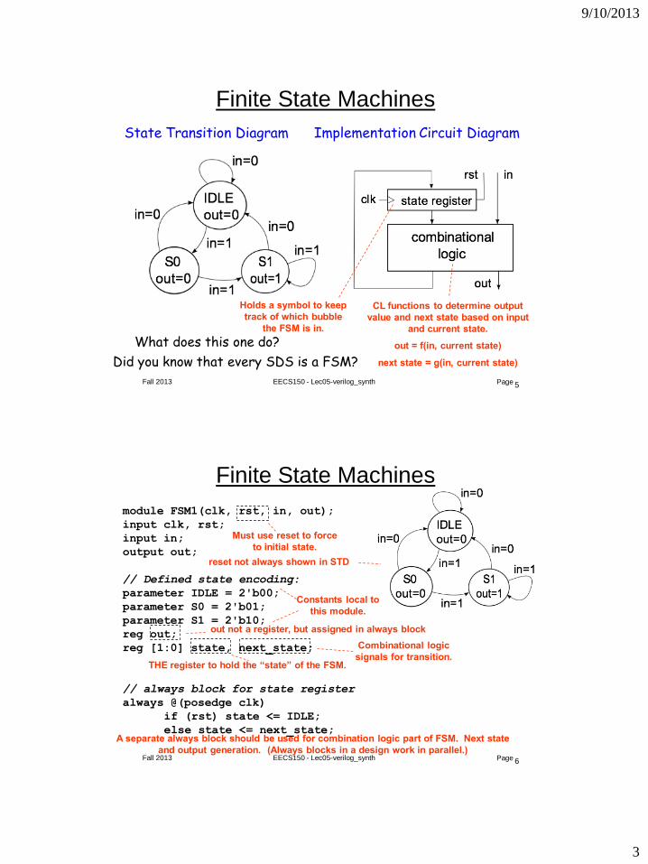
Finite State Machines
State Transition Diagram Implementation Circuit Diagram
Holds a symbol to keep
track of which bubble
the FSM is in.
CL functions to determine output
value and next state based on input
and current state.
out = f(in, current state)
next state = g(in, current state)
What does this one do?
Did you know that every SDS is a FSM?
6 Fall 2013 EECS150 - Lec05-verilog_synth Page
Finite State Machines
module FSM1(clk, rst, in, out);
input clk, rst;
input in;
output out;
// Defined state encoding:
parameter IDLE = 2'b00;
parameter S0 = 2'b01;
parameter S1 = 2'b10;
reg out;
reg [1:0] state, next_state;
// always block for state register
always @(posedge clk)
if (rst) state <= IDLE;
else state <= next_state;
Must use reset to force
to initial state.
reset not always shown in STD
out not a register, but assigned in always block
THE register to hold the “state” of the FSM.
Combinational logic
signals for transition.
Constants local to
this module.
A separate always block should be used for combination logic part of FSM. Next state
and output generation. (Always blocks in a design work in parallel.)
9/10/2013
4
7
Fall 2013
Page
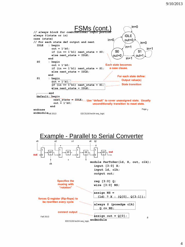
FSMs (cont.) // always block for combinational logic portion
always @(state or in)
case (state)
// For each state def output and next
IDLE : begin
out = 1’b0;
if (in == 1’b1) next_state = S0;
else next_state = IDLE;
end
S0 : begin
out = 1’b0;
if (in == 1’b1) next_state = S1;
else next_state = IDLE;
end
S1 : begin
out = 1’b1;
if (in == 1’b1) next_state = S1;
else next_state = IDLE;
end
default: begin
next_state = IDLE;
out = 1’b0;
end
endcase
endmodule
For each state define:
Each state becomes
a case clause.
Output value(s)
State transition
Use “default” to cover unassigned state. Usually
unconditionally transition to reset state.
EECS150 lec04-seq_logic
8 Fall 2013 Page
Example - Parallel to Serial Converter
module ParToSer(ld, X, out, clk);
input [3:0] X;
input ld, clk;
output out;
reg [3:0] Q;
wire [3:0] NS;
assign NS =
(ld) ? X : {Q[0], Q[3:1]};
always @ (posedge clk)
Q <= NS;
assign out = Q[0];
endmodule 8
Specifies the
muxing with
“rotation”
forces Q register (flip-flops) to
be rewritten every cycle
connect output
ld
out out
EECS150 lec04-seq_logic
9/10/2013
5
9 Fall 2013 EECS150 - Lec05-verilog_synth Page
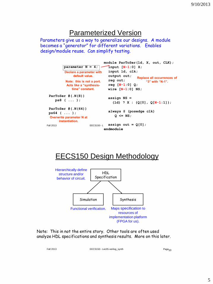
Parameterized Version
module ParToSer(ld, X, out, CLK);
input [3:0] X;
input ld, clk;
output out;
reg out;
reg [3:0] Q;
wire [3:0] NS;
assign NS =
(ld) ? X : {Q[0], Q[3:1]};
always @ (posedge clk)
Q <= NS;
assign out = Q[0];
endmodule
module ParToSer(ld, X, out, CLK);
input [N-1:0] X;
input ld, clk;
output out;
reg out;
reg [N-1:0] Q;
wire [N-1:0] NS;
assign NS =
(ld) ? X : {Q[0], Q[N-1:1]};
always @ (posedge clk)
Q <= NS;
assign out = Q[0];
endmodule
Replace all occurrences of
“3” with “N-1”.
parameter N = 4;
Declare a parameter with
default value.
Note: this is not a port.
Acts like a “synthesis-
time” constant.
ParToSer #(.N(8))
ps8 ( ... );
ParToSer #(.N(64))
ps64 ( ... );
Overwrite parameter N at
instantiation.
Parameters give us a way to generalize our designs. A module becomes a “generator” for different variations. Enables design/module reuse. Can simplify testing.
10 Fall 2013 EECS150 - Lec05-verilog_synth Page
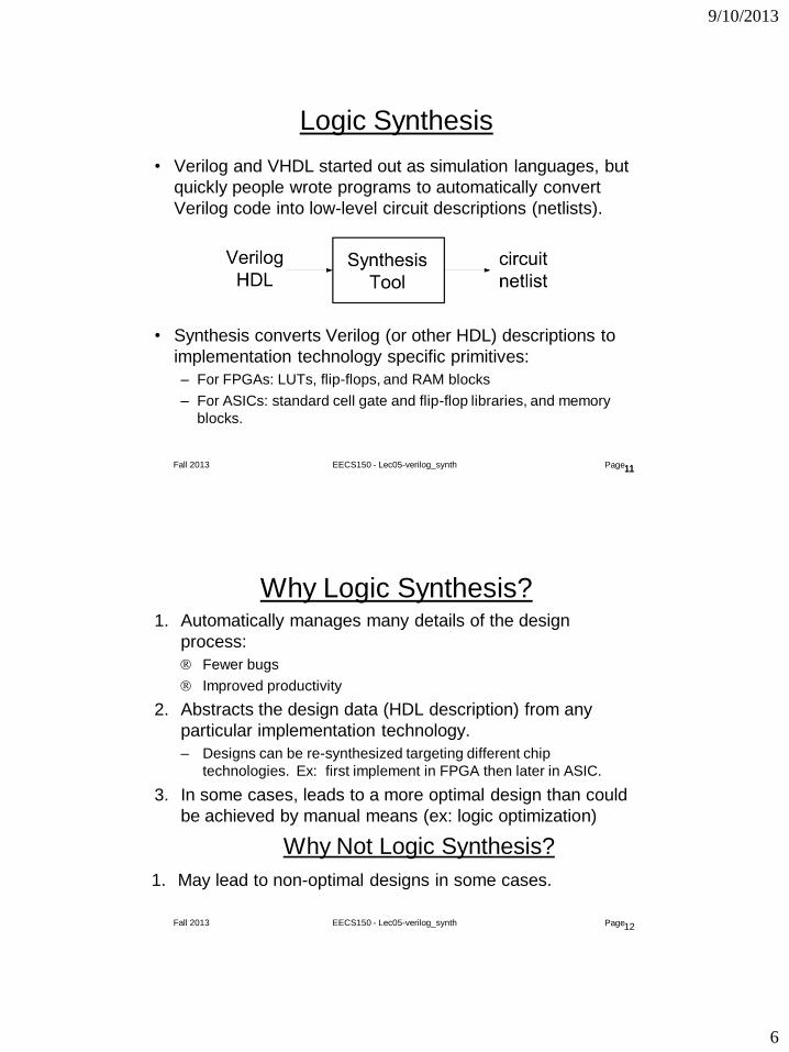
EECS150 Design Methodology
HDL Specification
Hierarchically define
structure and/or
behavior of circuit.
Simulation
Functional verification.
Synthesis
Maps specification to
resources of
implementation platform
(FPGA for us).
Note: This in not the entire story. Other tools are often used analyze HDL specifications and synthesis results. More on this later.
9/10/2013
6
11 Fall 2013 EECS150 - Lec05-verilog_synth Page
Logic Synthesis
• Verilog and VHDL started out as simulation languages, but
quickly people wrote programs to automatically convert
Verilog code into low-level circuit descriptions (netlists).
• Synthesis converts Verilog (or other HDL) descriptions to
implementation technology specific primitives:
– For FPGAs: LUTs, flip-flops, and RAM blocks
– For ASICs: standard cell gate and flip-flop libraries, and memory
blocks.
11
12 Fall 2013 EECS150 - Lec05-verilog_synth Page
Why Logic Synthesis? 1. Automatically manages many details of the design
process:
Fewer bugs
Improved productivity
2. Abstracts the design data (HDL description) from any
particular implementation technology.
– Designs can be re-synthesized targeting different chip
technologies. Ex: first implement in FPGA then later in ASIC.
3. In some cases, leads to a more optimal design than could
be achieved by manual means (ex: logic optimization)
Why Not Logic Synthesis?
1. May lead to non-optimal designs in some cases.
9/10/2013
7
13 Fall 2013 EECS150 - Lec05-verilog_synth Page
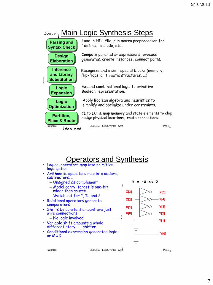
Main Logic Synthesis Steps Parsing and
Syntax Check
Design
Elaboration
Inference
and Library
Substitution
Logic
Expansion
Logic
Optimization
Partition,
Place & Route
Load in HDL file, run macro preprocessor for `define, `include, etc..
Compute parameter expressions, process generates, create instances, connect ports.
Recognize and insert special blocks (memory, flip-flops, arithmetic structures, ...)
Expand combinational logic to primitive Boolean representation.
Apply Boolean algebra and heuristics to simplify and optimize under constraints.
CL to LUTs, map memory and state elements to chip, assign physical locations, route connections.
foo.v
foo.ncd
14 Fall 2013 EECS150 - Lec05-verilog_synth Page
Operators and Synthesis • Logical operators map into primitive
logic gates • Arithmetic operators map into adders,
subtractors, … – Unsigned 2s complement – Model carry: target is one-bit
wider than source – Watch out for *, %, and /
• Relational operators generate comparators
• Shifts by constant amount are just wire connections
– No logic involved • Variable shift amounts a whole
different story --- shifter • Conditional expression generates logic
or MUX
Y = ~X << 2
X[3]
Y[0]
Y[1]
Y[2] X[0]
X[1]
X[2]
Y[3]
Y[4]
Y[5]
9/10/2013
8
15 Fall 2013 EECS150 - Lec05-verilog_synth Page
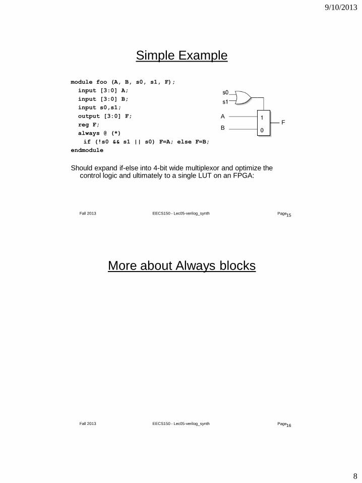
Simple Example
module foo (A, B, s0, s1, F);
input [3:0] A;
input [3:0] B;
input s0,s1;
output [3:0] F;
reg F;
always @ (*)
if (!s0 && s1 || s0) F=A; else F=B;
endmodule
Should expand if-else into 4-bit wide multiplexor and optimize the control logic and ultimately to a single LUT on an FPGA:
A
B F
16 Fall 2013 EECS150 - Lec05-verilog_synth Page
More about Always blocks
9/10/2013
9
17 Fall 2013 EECS150 - Lec05-verilog_synth Page
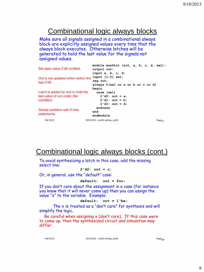
Combinational logic always blocks Make sure all signals assigned in a combinational always block are explicitly assigned values every time that the always block executes. Otherwise latches will be generated to hold the last value for the signals not assigned values.
module mux4to1 (out, a, b, c, d, sel);
output out;
input a, b, c, d;
input [1:0] sel;
reg out;
always @(sel or a or b or c or d)
begin
case (sel)
2'd0: out = a;
2'd1: out = b;
2'd3: out = d;
endcase
end
endmodule
Sel case value 2’d2 omitted.
Out is not updated when select line
has 2’d2.
Latch is added by tool to hold the
last value of out under this
condition.
Similar problem with if-else
statements.
18 Fall 2013 EECS150 - Lec05-verilog_synth Page
To avoid synthesizing a latch in this case, add the missing select line: 2'd2: out = c;
Or, in general, use the “default” case:
default: out = foo;
If you don’t care about the assignment in a case (for instance you know that it will never come up) then you can assign the value “x” to the variable. Example: default: out = 1‘bx;
The x is treated as a “don’t care” for synthesis and will simplify the logic. Be careful when assigning x (don’t care). If this case were to come up, then the synthesized circuit and simulation may differ.
Combinational logic always blocks (cont.)
9/10/2013
10
19 Fall 2013 EECS150 - Lec05-verilog_synth Page
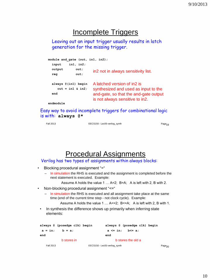
module and_gate (out, in1, in2);
input in1, in2;
output out;
reg out;
always @(in1) begin
out = in1 & in2;
end
endmodule
Incomplete Triggers Leaving out an input trigger usually results in latch generation for the missing trigger.
Easy way to avoid incomplete triggers for combinational logic is with: always @*
in2 not in always sensitivity list.
A latched version of in2 is
synthesized and used as input to the
and-gate, so that the and-gate output
is not always sensitive to in2.
20 Fall 2013 EECS150 - Lec05-verilog_synth Page
Procedural Assignments
• Blocking procedural assignment “=“
– In simulation the RHS is executed and the assignment is completed before the
next statement is executed. Example:
Assume A holds the value 1 … A=2; B=A; A is left with 2, B with 2.
• Non-blocking procedural assignment “<=“
– In simulation the RHS is executed and all assignment take place at the same
time (end of the current time step - not clock cycle). Example:
Assume A holds the value 1 … A<=2; B<=A; A is left with 2, B with 1.
Verilog has two types of assignments within always blocks:
• In synthesis the difference shows up primarily when inferring state
elements:
always @ (posedge clk) begin always @ (posedge clk) begin
a = in; b = a; a <= in; b<= a;
end end
b stores in b stores the old a
9/10/2013
11
21 Fall 2013 EECS150 - Lec05-verilog_synth Page
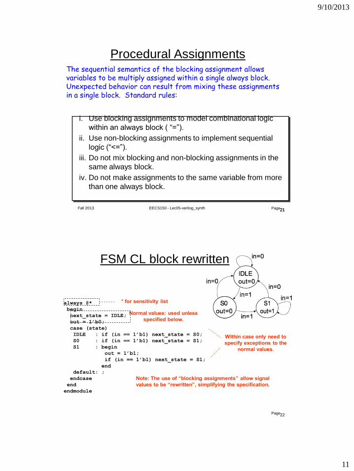
Procedural Assignments The sequential semantics of the blocking assignment allows variables to be multiply assigned within a single always block. Unexpected behavior can result from mixing these assignments in a single block. Standard rules:
i. Use blocking assignments to model combinational logic
within an always block ( “=”).
ii. Use non-blocking assignments to implement sequential
logic (“<=”).
iii. Do not mix blocking and non-blocking assignments in the
same always block.
iv. Do not make assignments to the same variable from more
than one always block.
21
22 Fall 2013 EECS150 - Lec05-verilog_synth Page
FSM CL block rewritten always @(state or in)
case (state)
IDLE : begin
out = 1’b0;
if (in == 1’b1) next_state = S0;
else next_state = IDLE;
end
S0 : begin
out = 1’b0;
if (in == 1’b1) next_state = S1;
else next_state = IDLE;
end
S1 : begin
out = 1’b1;
if (in == 1’b1) next_state = S1;
else next_state = IDLE;
end
default: begin
next_state = IDLE;
out = 1’b0;
end
endcase
endmodule
always @*
begin
next_state = IDLE;
out = 1’b0;
case (state)
IDLE : if (in == 1’b1) next_state = S0;
S0 : if (in == 1’b1) next_state = S1;
S1 : begin
out = 1’b1;
if (in == 1’b1) next_state = S1;
end
default: ;
endcase
end
endmodule
* for sensitivity list
Normal values: used unless
specified below.
Within case only need to
specify exceptions to the
normal values.
Note: The use of “blocking assignments” allow signal
values to be “rewritten”, simplifying the specification.
9/10/2013
12
23 Fall 2013 EECS150 - Lec05-verilog_synth Page
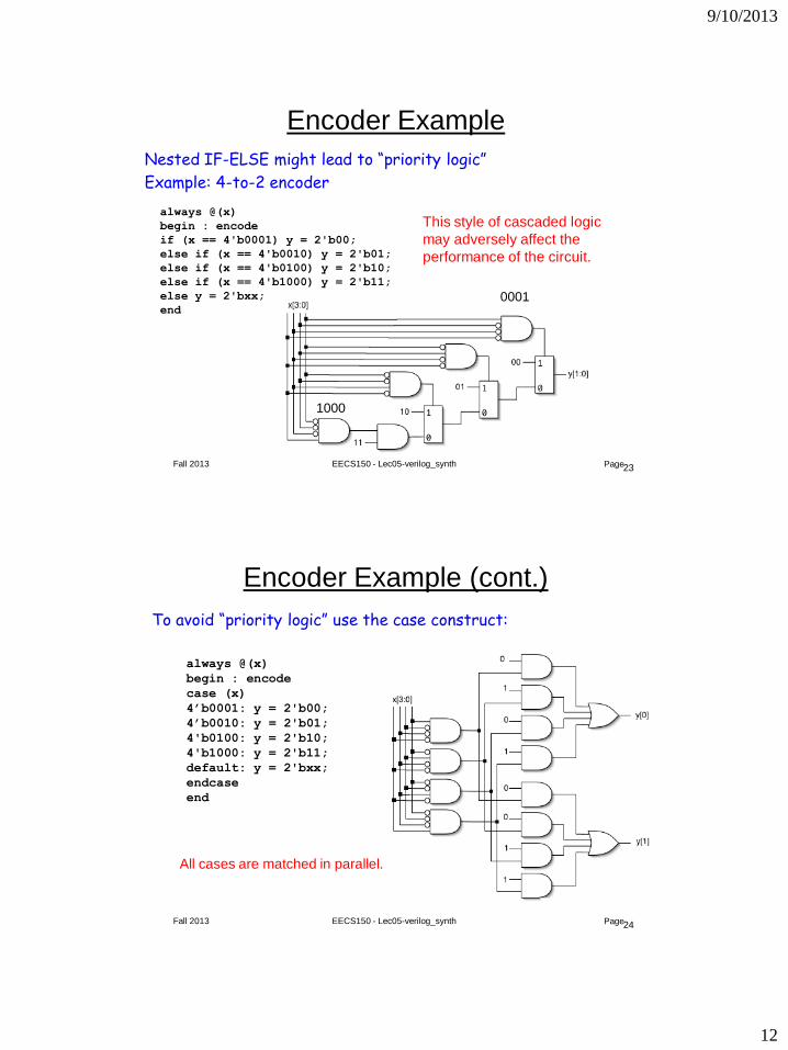
Encoder Example
Nested IF-ELSE might lead to “priority logic”
Example: 4-to-2 encoder
always @(x)
begin : encode
if (x == 4'b0001) y = 2'b00;
else if (x == 4'b0010) y = 2'b01;
else if (x == 4'b0100) y = 2'b10;
else if (x == 4'b1000) y = 2'b11;
else y = 2'bxx;
end
This style of cascaded logic
may adversely affect the
performance of the circuit.
0001
1000
24 Fall 2013 EECS150 - Lec05-verilog_synth Page
Encoder Example (cont.)
To avoid “priority logic” use the case construct:
always @(x)
begin : encode
case (x)
4’b0001: y = 2'b00;
4’b0010: y = 2'b01;
4'b0100: y = 2'b10;
4'b1000: y = 2'b11;
default: y = 2'bxx;
endcase
end
All cases are matched in parallel.
9/10/2013
13
25 Fall 2013 EECS150 - Lec05-verilog_synth Page
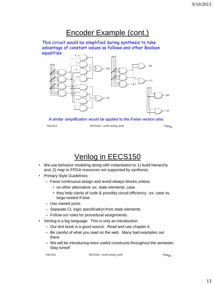
Encoder Example (cont.)
A similar simplification would be applied to the if-else version also.
This circuit would be simplified during synthesis to take advantage of constant values as follows and other Boolean equalities:
26 Fall 2013 EECS150 - Lec05-verilog_synth Page
Verilog in EECS150 • We use behavior modeling along with instantiation to 1) build hierarchy
and, 2) map to FPGA resources not supported by synthesis.
• Primary Style Guidelines:
– Favor continuous assign and avoid always blocks unless:
• no other alternative: ex: state elements, case
• they help clarity of code & possibly circuit efficiency : ex: case vs,
large nested if else
– Use named ports.
– Separate CL logic specification from state elements.
– Follow our rules for procedural assignments.
• Verilog is a big language. This is only an introduction.
– Our text book is a good source. Read and use chapter 4.
– Be careful of what you read on the web. Many bad examples out
there.
– We will be introducing more useful constructs throughout the semester.
Stay tuned!
9/10/2013
14
27 Fall 2013 EECS150 - Lec05-verilog_synth Page
Final thoughts on Verilog Examples
Verilog may look like C, but it describes hardware! (Except in
simulation “test-benches” - which actually behave like
programs.)
Multiple physical elements with parallel activities and temporal
relationships.
A large part of digital design is knowing how to write Verilog
that gets you the desired circuit. First understand the circuit
you want then figure out how to code it in Verilog. If you do
one of these activities without the other, you will struggle.
These two activities will merge at some point for you.
Be suspicious of the synthesis tools! Check the output of the
tools to make sure you get what you want.