eeembedded d6.1 cloud-based simulation and optimization...
TRANSCRIPT

© eeEmbedded Consortium www.eeEmbedded.eu
This project has received funding from the European Union Seventh Framework Programme
under grant agreement n° 609349.
OPTIMISED DESIGN METHODOLOGIES FOR ENERGY-EFFICIENT BUILDINGS INTEGRATED IN THE NEIGHBOURHOOD ENERGY SYSTEMS
eeEmbedded – D6.1
Cloud-based simulation and optimization framework
Responsible Authors:
Byron Protopsaltis, Theodora Pappou, Thrasos Rekouniotis
Co-Authors:
Ken Baumgärtel, Romy Guruz, Michael Polter, Peter Katranuschkov
Due date: 31.12.2015
Issue date: 25.01.2016
Nature: Other
Coordinator: R. J. Scherer, Institute for Construction Informatics, Technische Universität Dresden, Germany

D6.1 Cloud-based simulation and optimization framework Version 1.0 Page 2/26
© eeEmbedded Consortium www.eeEmbedded.eu
Start date of project: 01.10.2013 Duration: 48 months
Organisation name of lead contractor for this deliverable: SOFiSTik Hellas
History
Version Description Lead Author Date
0.1 Deliverable Structure Theodora Pappou 02.06.2015
0.2 Request for Approval Byron Protopsaltis 04.12.2015
0.3 Software Architecture Thrasos Rekouniotis 27.12.2015
0.4 Internal Final Revision Byron Protopsaltis 28.12.2015
1.0 Final Revision Romy Guruz, Michael Polter 26.01.2016
Copyright
This report is © eeEmbedded Consortium 2014. Its duplication is restricted to the personal use within the consortium, the funding agency and the project reviewers. Its duplication is allowed in its integral form only for anyone's personal use for the purposes of research or education.
Citation
Protopsaltis B., Pappou T., Rekouniotis T. (2016); eeEmbedded Deliverable D6.1: Cloud-based simulation and optimization framework © eeEmbedded Consortium, Brussels.
Acknowledgements
The work presented in this document has been conducted in the context of the seventh framework programme of the European community project eeEmbedded (n° 609349). eeEmbedded is a 48 month project that started in October 2013 and is funded by the European Commission as well as by the industrial partners. Their support is gratefully appreciated. The partners in the project are Technische Universität Dresden (Germany), Fraunhofer-Gesellschaft zur Förderung der angewandten Forschung E.V (Germany), NEMETSCHEK Slovensko, S.R.O. (Slovakia), Data Design System ASA (Norway), RIB Information Technologies AG (Germany), Jotne EPM Technology AS (Norway), Granlund OY (Finland), SOFISTIK HELLAS AE (Greece), Institute for applied Building Informatics IABI (Germany), FR. SAUTER AG (Switzerland), , Obermeyer Planen + Beraten (Germany), Centro de Estudios Materiales y Control de Obras S.A. (Spain), STRABAG AG (Austria) and Koninklijke BAM Group NV (The Netherlands). This report owes to a collaborative effort of the above organizations.
Project of SEVENTH FRAMEWORK PROGRAMME OF THE EUROPEAN COMMUNITY
Dissemination Level
PU Public X
PP Restricted to other programme participants (including the Commission Services)
RE Restricted to a group specified by the consortium (including the Commission Services)
CO Confidential, only for members of the consortium (including the Commission Services)

D6.1 Cloud-based simulation and optimization framework Version 1.0 Page 3/26
© eeEmbedded Consortium www.eeEmbedded.eu
Contents
1. Introduction .................................................................................................................................... 6
1.1 Purpose of the document ....................................................................................................... 6
1.2 Motivation .............................................................................................................................. 6
1.3 Cloud computing ..................................................................................................................... 8
1.4 HPC on the cloud-State of the art .......................................................................................... 9
2. REQUIREMENTS ............................................................................................................................ 13
2.1 Functional requirements ...................................................................................................... 13
2.2 Non Functional Requirements ............................................................................................. 13
2.3 Modeling and interoperability requirements ...................................................................... 14
2.4 Parametric Simulation, Sensitivity analysis requirements .................................................. 14
2.5 Monitoring /management requirements ............................................................................ 15
2.6 Simulation evaluator requirements ..................................................................................... 16
2.7 Simulation model generator ................................................................................................ 17
3. Cloud Architecture ........................................................................................................................ 18
3.1 Context .................................................................................................................................. 18
3.2 Logical View .......................................................................................................................... 18
3.3 Component View .................................................................................................................. 19
3.4 Cloud Broker Service API ...................................................................................................... 19
4. Prototype IMPLEMENTATION ...................................................................................................... 21
4.1 Prototype Hardware specification ....................................................................................... 21
4.2 Prototype Software specification......................................................................................... 21
4.3 eeEmbedded specific software and services ....................................................................... 21
4.4 Energy Simulation software based on zonal models –TRNSYS (IET) ................................... 22
4.5 CFD Simulations .................................................................................................................... 23
5. CONCLUSIONS ............................................................................................................................... 25
D6.1 Cloud-based simulation and optimization framework Version 1.0 Page 4/26
© eeEmbedded Consortium www.eeEmbedded.eu
Acronyms
API Application Programming Interface
ASP Application Service Provider
AWS Amazon web Services
BACS Building Automation and Control System
BIM Building Information Modeling (Model)
CFD Computational Fluid Dynamics
EAPPM European Association of Product and Process Modeling
ECPPM European Conference on Product and Process Modeling
eeB Energy-efficient Buildings
eeBIM Energy enhanced Building Information Model
EEP Energy Efficiency Plan
ES Energy Simulation
FM Facility Management
GPU Graphics Processing Unit
HESMOS ICT Platform for Holistic Energy Efficiency Simulation and Lifecycle Management Of Public Use Facilities
HPC High Performance Computing
HTTP Hypertext Transfer Protocol (world wide web protocol)
HVAC Heating, Ventilating, and Air Conditioning
IaaS Infrastructure as a Service
ICT Information and Communication Technology
IDC International Data Corporation
IFC Industry Foundation Classes
IRT Infrastructure Response Time
ISES Intelligent Services For Energy-Efficient Design and Life Cycle Simulation (EU FP7 Research Project)
IT Information Technology

D6.1 Cloud-based simulation and optimization framework Version 1.0 Page 5/26
© eeEmbedded Consortium www.eeEmbedded.eu
IVEL Integrated Virtual Energy Laboratory
KPA Key Point Analysis
KPI Key Performance Indicators
LC Life Cycle
LCA Life Cycle Analysis
LCC Life Cycle Cost
MMVAV Multi Model Navigator
MTTF Mean Time To Failure
MTTR Mean Time To Repair
NIST National Institute for Standards and Technology
PaaS Platform as a Service
PPP Public Private Partnership
ScM Scenario Manager
SOA Service Oriented Architecture
TRNSYS Energy Simulation software
WAN Wide Area Network
WP Work Package
XML Extensible Mark-up Language

D6.1 Cloud-based simulation and optimization framework Version 1.0 Page 6/26
© eeEmbedded Consortium www.eeEmbedded.eu
1. Introduction
This document provides a description of the Cloud-based simulation and optimization framework in the context of eeEmbedded. This work has been done within WP6 task T6.1 of the project. The subject of WP6 is about the seamless integration of the numerical investigations and simulations
in the eeeDesign process which requires (1) mapping services to map the eeeBIM models, i.e. the
multi information model, to a respective multi-physics model, and (2) preparing the simulation and
optimization tools to run on Cloud, benefiting from the new cloud-based optimization of parallel and
sequential iterations. This includes also development of pre-evaluation mechanisms of the input set
quantities to enable parallel runs as well as development of result evaluation services for quantifying
the “AS-IS” KPIs and the required different visualization views. An open source framework such as
OpenStack or CloudStack will be used to provide the needed cloud functionality
Task 6.1 deals with the execution of the simulation applications on the cloud as far as their input parameters and data models have been prepared according to the work of tasks 6.2 and 6.3. In the current task some particular simulation applications of eeEmbedded are executed on the cloud as a part of a holistic optimization procedure.
Besides the technical interface, i.e. the wrapping services needed to encapsulate the numerical tools for the cloud computation, the framework for generating and managing the simulations and in particular for evaluating their results is being developed. This framework is complemented by an optimization method, in which feedback cycles will be implemented to iteratively optimize the results. In this way, eeEmbedded will realize a holistic optimization strategy that combines parallel cloud runs (based on pre-assumptions of the domain to cover the potential optimum) with sequential optimization (based on feedback from former runs).
1.1 Purpose of the document
The purpose of this document is to provide a description of the eeEmbedded established cloud-
based test-bed. This work is being implemented within WP6 task T6.1 of the project.
The specific task objective was to establish a cloud-based test-bed on the basis of the requirements and
use cases from WP1 (architecture and requirements), the work done in WP2 for KPI-based design
method, WP3 for energy design targets, WP4 for data models for multiphysics energy simulations, and
WP5 for interoperability needs and system ontology. Cloud computing power is properly utilized
according to the needs of each simulation application towards the common target for the achievement
of the optimum solution based on multidisciplinary criteria all quantified in specialized KPIs.
1.2 Motivation
eeEmbedded will develop an open BIM-based holistic collaborative design and simulation platform, a related holistic design methodology, an energy system information model and an integrated information management framework for designing energy-efficient buildings and their optimal energetic embedding in the neighborhood of surrounding buildings and energy systems. A new design control and monitoring system based on hierarchical key performance indicators will support the complex design collaboration process. Knowledge-based detailing templates will allow energy simulations already in the early design phase, and BIM-enabled interoperability grounded on a novel system ontology will provide for a seamless holistic design process with distributed experts, and a seamless integration of simulations in the virtual design office (energy performance, CO2, CFD, control system, energy system, climate change, user behaviour, construction, facility operation), thus

D6.1 Cloud-based simulation and optimization framework Version 1.0 Page 7/26
© eeEmbedded Consortium www.eeEmbedded.eu
extending it to a real virtual design lab. A new ontology-based Link Model will provide the bridge between the multiple physical and mathematical models involved in the eeBuilding domain warranting the desired data and services interoperability. The use of specialized simulation software on the cloud for the energy performance and the thermal comfort of buildings embedded in their environment gives an extra value on the project’s outcome following the trend for use of commercial specialized software on the cloud:
“80% of new commercial enterprise apps will be deployed on cloud platforms (in 2012)” (IDC)[
http://www.idc.com/getdoc.jsp?containerId=prUS23177411#.UVzRhpOAqDk].
According to Gartner [http://www.gartner.com/newsroom/id/2352816], the total turnover of
the public cloud services would come to $ 131 billion this year (2013), more than $ 111 billion
than the previous year. The turnover of cloud services will reach $ 677 billion for the years 2013
to 2016
According to Gartner
[https://www.gartner.com/doc/2718918?ref=SiteSearch&sthkw=cloud%20turnover&fnl=search
&srcId=1-3478922254]
o by 2015, 50% of all new application independent software vendors will be pure SaaS
providers.
o through 2015, more than 90% of private cloud computing deployments will be for
infrastructure as a service.
o by 2015, 50% of large global enterprises will rely on external cloud computing services
for at least one of their top 10 revenue-generating processes.
o by 2016, all large global enterprises will use some level of public cloud services.
o by 2016, most SaaS contracts will include price escalation limitations and the ability to
terminate contracts.
o by 2017, over 50% of large SaaS application providers will offer matching business
process services and an integrated platform as a service.
o through 2017, 80% of large enterprises will restrict their private cloud data center
services to less than 20% of their total data center services.
o through 2020, the most common use of cloud services will be a hybrid model combining
on-premises and external cloud services.
In fact, International Data Corporation (IDC) predicts the number of new cloud-based solutions
will triple in the next four to five years. IDC asserts that cloud services will remain the essential
foundation of the IT industry's 3rd Platform of growth. As the cloud market enters an "innovation
stage," there will be an explosion of new solutions and value creation on top of the cloud. IDC
predicts that there will be more industry-specific cloud services platforms and marketplaces run
by leaders in each industry seeking to attract communities of thousands of innovators to create
valuable new services. IDC predicts that the public cloud computing will reach almost $70 billion
in 2015 worldwide, with the top 5 verticals (discrete manufacturing, banking, professional
services, process manufacturing, and retail) accounting for approximately 45% of the total spend
for the market.
Particular attention should be given to the measured and expected improvement of these figures
for public cloud services compared to the traditional IT Services. Compared to a modest increase
of 2.3% in global IT Services, public cloud services had an increase of more than 19.7%!
It is clear from the above that the cloud market will continue becoming bigger and bigger every
year, creating an ideal environment for new products and ideas. The current project

D6.1 Cloud-based simulation and optimization framework Version 1.0 Page 8/26
© eeEmbedded Consortium www.eeEmbedded.eu
eeEmbedded moves into that direction, leveraging existing knowledge and software solutions
and transforming them into cloud-based solutions.
1.3 Cloud computing
With the rapid development of processing and storage technologies and the success of the Internet,
computing resources have become cheaper, more powerful and more ubiquitously available than
ever before. This fact has recently enabled the realization of a new computing model called cloud
computing, in which resources are provided as general utilities that can be leased and released by
users through the Internet in an on-demand fashion. The relevant definition according to the USA
National Institute for Standards and Technology (NIST) is the following: Cloud computing is a model
for enabling convenient, on-demand network access to a shared pool of configurable computing
resources (e.g., networks, servers, storage, applications, and services) that can be rapidly provisioned
and released with minimal management effort or service provider interaction. The main reason for
the existence of different perceptions of cloud computing is that cloud computing, unlike other
technical terms, is not a new technology, but rather a new operations model that brings together a
set of existing technologies to run business in a different way [NIST].
A typical cloud computing environment can be divided into the following 4 distinct layers:
- Hardware/data center layer: this is responsible for managing the physical resources of the cloud,
including physical servers, routers, switches, power and cooling systems. Typical issues at this layer
include hardware configuration, fault-tolerance, traffic management, power and cooling resource
management.
- Infrastructure layer: this layer creates a pool of storage and computing resources by partitioning
the physical resources using virtualization technologies. The infrastructure layer is an essential
component of cloud computing, since many key features, such as dynamic resource assignment, are
only made available through virtualization technologies.
- Platform layer: Built on top of the infrastructure layer, the platform layer consists of operating
systems and application frameworks. The purpose of the platform layer is to minimize the burden of
deploying applications directly into virtual machine containers.
- Application layer: This is the top level of the hierarchy and consists of the actual cloud applications.
In contrast to traditional applications, cloud applications can leverage the automatic-scaling feature
to achieve better performance, availability and lower operating cost.
Cloud computing employs a service-driven business model. In other words, hardware and platform-
level resources are provided as services on an on-demand basis. Conceptually, every layer of the
architecture described before can be implemented as a service to the layer above. Conversely, every
layer can be perceived as a customer of the layer below. In practice, clouds offer services that can be
grouped into three categories [NIST]:
Software as a Service (SaaS). The capability provided to the consumer is to use the provider’s
applications running on a cloud infrastructure2. The applications are accessible from various
client devices through either a thin client interface, such as a web browser (e.g., web-based
email), or a program interface. The consumer does not manage or control the underlying cloud
infrastructure including network, servers, operating systems, storage, or even individual
application capabilities, with the possible exception of limited user-specific application
configuration settings.

D6.1 Cloud-based simulation and optimization framework Version 1.0 Page 9/26
© eeEmbedded Consortium www.eeEmbedded.eu
Platform as a Service (PaaS). The capability provided to the consumer is to deploy onto the cloud
infrastructure consumer-created or acquired applications created using programming without
being able to manage or control the underlying cloud infrastructure including network, servers,
operating systems, or storage, but has control over the deployed applications.
Infrastructure as a Service (IaaS). The capability provided to the consumer is to provision
processing, storage, networks, and other fundamental computing resources where the consumer
is able to deploy and run arbitrary software, which can include operating systems and
applications. The consumer does not manage or control the underlying cloud infrastructure but
has control over operating systems, storage, and deployed applications; and possibly limited
control of select networking components (e.g., host firewalls).
Figure 1: Typical Cloud Architecture
1.4 HPC on the cloud-State of the art
Simulations in the context of eeEmbedded come under the category of High Performance Computations (HPC) whether it is about the thousands of alternative runs of zonal model simulations or the runs of really “heavy” models of CFD simulations. For each type of analysis different aspects of cloud computing are mobilized. HPC has been traditionally confused with Supercomputers, i.e. systems with the ability to execute
tremendous amounts of calculations in a short time. According to Wikipedia, “a supercomputer is
a computer at the frontline of current processing capacity, particularly speed of calculation". Today,
most of supercomputers rely on massive processing resources (CPUs, memory, etc.) that are utilized
in parallel for the execution of a single problem. They are generally arranged either as a grid or as a
cluster of computers or a combination of both. Grids are loosely coupled computing resources that
contribute for the execution of tasks. They typically involve heterogeneous resources as well and are
suitable for problems that may solve small pieces of the problem independently and have the results
combined at the end. On the other hand, a cluster typically consists of closely located computers that
communicate with each other via high speed communication links. Clusters, on the other hand, are
frequently composed of homogeneous resources and, due to the high performance links, are more
often used for problems requiring frequent exchange of intermediate results.
D6.1 Cloud-based simulation and optimization framework Version 1.0 Page 10/26
© eeEmbedded Consortium www.eeEmbedded.eu
CFD is clearly one of the major HPC applications. It requires highly intense computations where the
workload is aligned with the parallel processing methodologies. In parallel processing,
communication is a significant performance factor. The vast majority of CFD parallel codes in the past
, including those in eeEmbedded, have been mainly based on the MPI protocol. They are latency
sensitive and generally experience noticeable slowdowns, dependent on application messaging
profiles. Obviously, any further latency reduction is welcome to improve MPI performance over time.
In summary, CFD are HPC applications that require:
• high computing power, • high performance interconnects and • fast connectivity to storage or file system.
According to the needs of CFD described above, in order to use cloud infrastructure for HPC/CFD, the cloud needs to:
• be based on HPC components, • be connected with high performance, low latency and high throughput interconnects, • be located in the same physical area as much as possible (for example InfiniBand connections
vs. WAN).
Until recently, HPC has not been a good candidate for cloud computing due to its requirement for
tight hardware integration. Cloud environments can be formed by non-homogeneous systems that
are widely separated and therefore connected together with low performance interconnection. Thus,
they are not well suited for HPC applications. In earlier versions of cloud computing the
communication overhead made only coarse-grained parallelism feasible. As cloud computing
transitioned to next generation virtualized and elastic cloud architectures, high performance and
resilient cloud networking became a requirement. Network technologies such as InfiniBand that
deliver low latency, fast response, and increasing performance have been lately adopted by cloud
providers. It is noticeable that 52 systems of the TOP 100 supercomputers list (Nov. 2012) use
InfiniBand interconnect technology.
Cloud computing virtualization capabilities can increase the simplicity for managing HPC in the cloud.
Achieving native application performance and scalability in cloud computing environment will enable
HPC to be effectively extended in such environments. Thus, it will be made possible for SME
companies and small research organizations to utilize HPC resources across the world for better
research, education, and product development. To be able to use cloud infrastructure for HPC, the
cloud needs to be based on HPC components.
The maximum cluster utilization and computing capacity are expected when a private cloud is
created (i.e. a cloud within an organization) with unified computational resources (Shainer et al,
2009). Due to the fact that CFD engineering simulations are time-consuming, they are also cost
expensive. Consequently, an additional requirement arises for the infrastructure, namely that their
deployment should be limited to clusters with a high level of security and complex architecture
maintained by specialized and “expensive” IT experts.
Cloud providers: new trends
Cloud providers, till recently, provided computing environments that resemble more grid than cluster
computing. The client rented a virtual machine that was not known where it was located, on which
D6.1 Cloud-based simulation and optimization framework Version 1.0 Page 11/26
© eeEmbedded Consortium www.eeEmbedded.eu
underlying hardware infrastructure, how many other clients were using simultaneously the shared
infrastructure and had a difficulty estimating the exact metrics of the allocated resource. This is
adequate for simple web applications with low computing requirements and sudden bursts of high
activity; it even suits them as the respective pricing is extremely low compared to a dedicated system
that is sized for the worst case scenario. Even today, this is the typical offering from major cloud
providers, such Amazon EC21
That uncertainty though increases the risks and the ability of the client to properly plan the required
infrastructure for his/her project; cloud providers realized the need and are already offering
solutions with guaranteed CPU, memory, storage and bandwidth specifications2).
Based on the description of CFD, it is clear that the required calculations are more suited to a cluster
of computers HPC solution than loosely coupled systems. Amazon and other cloud providers realized
that need and are already offering cluster instances on the cloud, on per hour rental basis3. It is
worth mentioning cloud-based supercomputers such as Amazon EC2 are already on the TOP 500
supercomputers list.
Similarly, an array of computers on a private cloud approximates very well the requirements of a
cluster of computers, computing power and offers exclusive, uniform material and high speed
communication between nodes. The majority of cloud computing providers have a price list and
promotions for such systems.
HPC Commercial applications – Large collaborative projects on the cloud
In the light of the above, large software providers are investing massively in IT solutions that involve cloud computing. For instance Amazon with its AWS4, Google with its AppEngine5, and Microsoft with Windows Azure6 offer powerful cloud systems for the development or deployment of various services.
Some ambitious projects have been dealt in the past with CFD simulations and cloud computing (for example Symscape Caedium, available in: http://www.symscape.com/product/caedium). This system offers the ability to outsource intensive CFD simulations to a cloud service but it doesn’t offer a cloud service and on the other hand is a general purposed CFD tool not-oriented to a specific domain of engineering design making is less accessible and convenient to use for energy related engineering calculations.
Another interesting cloud project for civil engineering is “Autodesk 360”7, that is a cloud-computing platform offering access to storage, a collaboration workspace and several cloud services. Energy and structural analyses, a conceptual design, and BIM (Building Information Modeling) management solutions are some of the services provided by Autodesk 360. Nevertheless, there are no services available for energy simulations and optimization procedure based on KPIs for energy management in the buildings’ environment. In eeEmbeded a virtual Energy Lab will be offered as a service via the web deployed on the cloud.
Recent improvements in hardware and software capabilities has allowed CFD detailed 3D analyses to be applied to building energy simulations for the determination of spatial distribution of thermal comfort indices inside particular spaces in buildings. Different companies with different responsibilities and knowledge are involved in civil construction projects. Problem definition and transformation of data and results is a very complex task and in most cases requires considerable effort. To overcome these issues, a comprehensive distributed infrastructure for CFD simulations of civil structures is needed. Such a distributed system should offer special services for performance sharing, data preparation, and self-organized data transmissions. These services should be delivered
D6.1 Cloud-based simulation and optimization framework Version 1.0 Page 12/26
© eeEmbedded Consortium www.eeEmbedded.eu
through a cloud-computing implementation. Not only should the cloud system accelerate the work process and the accuracy of the simulations during the construction project with the minimum investment but the different parties involved in the project should also work closer together and encourage teamwork. CFD companies, increasingly test nowadays their software on the cloud, trying various implementations and cloud infrastructures (private or public clouds).

D6.1 Cloud-based simulation and optimization framework Version 1.0 Page 13/26
© eeEmbedded Consortium www.eeEmbedded.eu
2. REQUIREMENTS
2.1 Functional requirements
The eeEmbedded Virtual Energy Laboratory will be accessible on the Internet via a standard Web Browser. It will support product manufacturers, architects, HVAC designers and energy experts, in new building design and retrofitting/refurbishment of existing buildings by enabling comprehensive simulation of energy efficiency and evaluation of performance and comfort, taking into account probabilistic input values and semi-stochastic computational methods. Moreover, different iteration cycles will be supported, as well as the fast and simultaneous examination of alternatives using high-throughput computing provided via cloud technology.
To achieve specification of the functional requirements to the Virtual Energy Laboratory, various relevant end-user activities were investigated and linked to the exchange requirements of the defined use cases.
The requirements will cover all the areas of the proposed system:
For the interaction with the end-user:
o Support User management : user registration, user’s profile management for common
settings
o Support task management per end user : project creation, creation of a task and the
allocation of required resources, task history with a list of previous projects/tasks , task
results visualization, queuing system etc.
For the integration with energy solvers:
o ease to formulate the model of the construction, type of design case and alternative
design cases
o the ability to evaluate the results for each design case separately according to user needs
o Support interoperability of all applications with the other systems of the framework
o Support resource Commission requests
For the functionality available to the administrator of the system:
o Management of the user base and their project/tasks
o Visualization of the resources used, financial information related to the project
execution, etc.
For the needs of the management service, controlling the execution nodes:
o Monitor the execution nodes
o Commission/decommission resources, allocate/de-allocate provisioned resources, etc.
o Support resiliency to compute node failures.
2.2 Non Functional Requirements
While the functional requirements define what the system is supposed to do, the non-functional requirements define how a system is supposed to be.
Portability: This requirement is related with the easiness of an application to be executed in
different platforms. Operating system selection of the images installed in the virtual
machines, CPU or GPU code support, 32 or 64 bits.
Reliability: concerns reliability of the hardware of the cloud Infrastructure (compute nodes,
storage disks, network interconnects). Indicators to be specified the Mean Time To Failure

D6.1 Cloud-based simulation and optimization framework Version 1.0 Page 14/26
© eeEmbedded Consortium www.eeEmbedded.eu
(MTTF) and the Mean Time To Repair (MMTR). Moreover, reliability can be also related with
resources required to run an application, with the number of machines, and with the type of
environment (OS etc).
Availability: This is related with the ability of the system to respond to user
requests.Relevant indicators are: the minimum percentage of uptime required, the different
locations where the application will be accessed from.
Efficiency: The efficiency is associated with HPC parallel CFD software performance. Relevant
values are: response time, throughput, scalability, network latency and workload expected
for the applications.
Cost: This requirement is related with how much the customer is willing to pay in order to be
provided with a service that supports all the additional non-functional requirements.(in case
the cloud platform service is provided by a commercial provider)
Legal and Licensing: The relevant terms and references of the platform will be created in
order to assure the licensing on the system.
Maintainability: The system will be accompanied by comprehensive documentation.
The Web container in which the system is planned to be deployed will be the Apache
Tomcat.
2.3 Modeling and interoperability requirements
Structured data exchange is necessary to ensure efficient support to the different actors of the eeEmbeded framework. It can greatly facilitate the coordinated use of information from working documents, the interoperability of different tools and the integration of energy templates and unstructured data (such as freeform text found in operational estimates, analysis, etc.). However, for a seamless sharing of data, the use of a common exchange model is also necessary. In ISES, the standardized open BIM, IFC, will be used for that purpose as well as BIM-based system ontology.
2.4 Parametric Simulation, Sensitivity analysis requirements
The solutions of eeEmbedded are focused on three main scenarios in the life-cycle of buildings and facilities that are identified with the sequential design phases of a building:
Urban design
Early design
Detailed design Each design phase includes Energy Simulation (ES) analysis based on zonal models with or without combination with detailed CFD simulations, LCA and LCC simulations and a decision making process based on a multidisciplinary optimization technique for the global optimization targeting to KPIs objectives. ES analysis concern the KPI estimation for various design alternatives on hourly or sub-hourly basis for periods of time ranging from a design day to a reference year or more. This type of simulation requires hundreds of thousands program executions, which do not require any exchange of data, between cloud nodes assigned to different applications. Weather models together with a stochastic internal loads model and stochastic operation of HVAC systems are being integrated within a building thermal model to obtain directly the probability distribution of building performance. The simulation outputs are the probabilistic components and the probabilistic building results. Regarding the analysis intent several semi-stochastic, deterministic and uncertain design parameters (variables) have to be applied to the Scenario Manager (ScM). In building component product development and design of facilities, almost all design parameters are subject to uncertainty. There are a few research

D6.1 Cloud-based simulation and optimization framework Version 1.0 Page 15/26
© eeEmbedded Consortium www.eeEmbedded.eu
efforts that have attempted to model the whole building under uncertainty, using over 1000 uncertain parameters when evaluating the energy efficiency of buildings. Similarly LCA/LCC estimation software performs stochastic analysis with parametric input the output of energy consumption rates and additional stochastic parameters related to the cost models used. The task is to properly identify the input parameter or a set of input parameters that have the least influence on the variability of the model outputs. These non-influential parameters can then be fixed at any given value of their range of uncertainty without reducing significantly the model output and without significant loss of information.
Performing sensitivity analyses can assess the sensibility of the model outcome to changes in the model inputs. The sensitivity analysis method provides a powerful tool to illustrate the consequences of alternative assumptions about a given model and as such, an important method for checking the quality of the model as well as for checking the robustness and reliability of the model analysis.
2.5 Monitoring /management requirements
Monitoring requirements concern cloud performance requirements and monitoring the convergence evolution of the simulations performed. Performance Monitoring of cloud should monitor the capability of components of cloud in delivering the expected service. To a large extend Clouds are based on virtualized resources. The Virtualized/Cloud environment requires a specialized monitoring solution which can provide effective, convenient and holistic view of the entire environment. A monitoring model is needed which can provide a view of the health of the entire cloud in delivering a service. It should help the provider assess whether user’s demands can be met with the current resources/performance. The monitoring of the Cloud performance can be broadly classified into 2 categories. Monitoring from Service providers and Monitoring from Cloud consumers’ view. 1. Infrastructure Performance - A Cloud service provider is interested in this kind of report. This involves performance of the various infrastructure components in the cloud like Virtual Machines, Storage, Network etc. Since individual component’s performance fail to provide an accurate view of the overall cloud performance, a new approach called Infrastructure Response Time is being researched upon to get a more accurate picture of the performance of a virtualized/ cloud environment. Infrastructure Response Time (IRT) is defined as the time it takes for any workload (application) to place a request for work on the virtual environment and for the virtual environment to complete the request (from the guest to spindle and back again). The request could be a simple data exchange between 2 VMs or a complex request which involves database transaction and writes into a storage array. [Definition from http://www.virtualinstruments.com/ files/pdfs/WP_APM-Experts-Infrastructure-Performance- Management-for-Virtualized-Systems.pdf] Key requirements for an Infrastructure Performance Management Solution for a Virtual/Cloud environment can be identified as below:
• Support any application hosted in the environment. Solution should be able to automatically
identify the applications and their topologies and this need to be independent of the application
architecture.
• Continuous discovery. Need to dynamically identify virtual and physical resources used by the
application at a given point in time.
• Infrastructure Response Time (IRT) must be calculated across the breadth & depth of the virtual
environment. Full scope of the environment needs to be considered.
• Be prepared for new applications and new infrastructure being added to the environment.
Solution should be able to automatically discover and calculate IRT for these new entrants as
well.
• Support for multiple platforms like VMware, Hyper-V etc
• Metrics/Parameters of Interest in Infrastructure Performance Monitoring

D6.1 Cloud-based simulation and optimization framework Version 1.0 Page 16/26
© eeEmbedded Consortium www.eeEmbedded.eu
Infrastructure Response Time is the Key metric along with the various resource utilization metrics as follows:
• CPU usage; total – all CPUs, per CPU, and delta between CPUs
• Disk usage; total, free, used
• Disk Latency
• Percentage Busy
• Percentage Ready
• Memory; percentage used, swap activity
• Network; bytes in/out
• Host System State
• Host System Resource Usage
• Virtual Machine Configuration
• Virtual Machine Stat
2. Application Performance - Performance of the applications hosted in the cloud. Cloud consumer, whose application is hosted in the cloud, is interested in this kind of report. In Calculating Application Performance also we cannot go by the resources utilized by the application as in a cloud, applications move around and so the monitoring solution needs to track and map them. Application Response Time is the key metric in Application Performance management which actually calculates the time taken for the application to respond to user requests. Since this is of more interest to the application owners, applications designed to be hosted in a cloud tend to have monitoring solution built in to the application itself. Additionally, monitoring of the convergence process, evaluation of the results in accordance to user needs should be ensured.
For example, during the CFD analysis, the monitoring of the convergence progress is critical, especially in the case of services on the cloud, where the cost is rated by the computing time. For example, the user often decides to change either some parameters affecting the numerical part of his analysis or the project he runs or even the whole model in accordance to the input he takes by the convergence history, based on his experience and intuition.
SOF’s CFD software has been enriched with more detailed monitoring sensors and the capability of user defined convergence criteria and convergence histories.
The evaluation of the results should also be oriented in accordance to user needs concerning each specific test case. To this end, it is required that some standard built in post-processing capabilities should be provided to the user, such as nodal values of specific variables (pressure, velocities etc), distribution of flow variables on region of interest if the flow field, as specific surfaces of a building or on a bridge deck etc.. This is very helpful for the experienced user and very crucial for the non-specialist user such as an architect, compared to the possibility to only provide him the results file and leave him free to post-process it by his own.
Thus, during task setup, the user will be able to select from a list of pre-defined flow quantities oriented to wind flows (such as lift and drag coefficient evolution in time, pressure coefficient distribution on windward and leeward faces of the building, etc.) to be monitored and graphically represented during the program execution and stored after the convergence is reached.
2.6 Simulation evaluator requirements
A simulation evaluator service will be developed comprising a set of services for the different functionalities of the simulation objectives of the different domains. It will be implemented as a toolbox, where single components can be readily re-used, similarly to the filter toolbox (T4.5). The simulation evaluator will also include the past evaluation of the simulation results to (a) find out the

D6.1 Cloud-based simulation and optimization framework Version 1.0 Page 17/26
© eeEmbedded Consortium www.eeEmbedded.eu
optimal set points or a range of optimal set points, e.g. for sensitivity, robustness or fragility studies or (b) to generate a feedback cycle for sequential optimization. The evaluation of the significant set of results, which constitutes the “AS-IS” KPIs and will be visualized to the end-user (see WP7), is also part of this task, e.g. climatically bad performing rooms, underperforming sub-systems or components of the energy system under certain conditions, etc.
Simulation evaluator requirements concern the formulation of proper design criteria for the evaluation of the results that are going to be used in the implementation of multi-objective and multidisciplinary optimization techniques.`
2.7 Simulation model generator
Simulation model generator is responsible for the generation of suitable models for the simulations in the context of eeEmbedded. Simulation model generator, concerns the extraction of data from the Multi Model enhanced with link models to the Building Elements (obtained from Multi Model Navigator) to proper data set for each translating multi model data combined with link models to their native format. So, multi-model mapper is actually a collection of services to be implemented separately by each application developer. The requirements for the simulation model generator concern the creation of complete data sets for each specific application including default values and applications’ particular templates.
Since various applications use data from others (BACS from HVAC, CFD from ES, LCA/LCC from FM etc), the most important requirement for Simulation model generator concerns the definition and the implementation of proper templates for the exchange of data between simulation applications. To this end input from the following deliverables should be considered.
D1.3 Interoperability and collaboration requirements
D4.1 BIM Multi Model
D4.2 ESIM Multi Model
D4.3 Link Model for Multi Model
D8.1 SOA platform architecture
D2.1 Holistic multi-disciplinary KPI-based design framework
D2.3 Holistic KPI based design methodology
D1.4 Requirements for knowledge based design support and templates
D2.2 Templates for fast semiautomatic detailing
D6.1 Cloud-based simulation and optimization framework Version 1.0 Page 18/26
© eeEmbedded Consortium www.eeEmbedded.eu
3. Cloud Architecture
3.1 Context
Due to the complexity of the calculations involved in ES all Of the ES applications offered within eeEmbedded can already be deployed in the cloud and are being extensively used on multi node clusters or cloud environments. Each application provider has already deployed its applications in a cloud system that suits him best according the requirements mentioned in the previous sections even before the start of eeEmbedded. The availability of all applications already on private or public cloud platforms is exploited in the work done in T6.1 so that existing as well as future ES applications can be easily adapted and offered as eeEmbedded services. To this end ,work within T6.1 produced a cloud framework abstraction (for the purpose of ES applications) that encompasses all major existing cloud Frameworks and can easily cope with future cloud frameworks with minimal developer effort .This work is based on the relevant work done in ISES 8project in order to develop a broker (adapter) service that translates requests from eeEmbedded service Bus to various cloud frameworks ,using plugins to implement different cloud engine interfaces.
3.2 Logical View
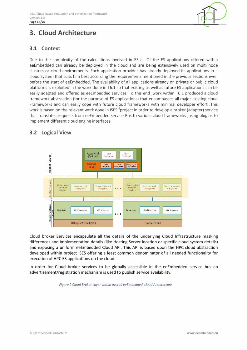
Cloud broker Services encapsulate all the details of the underlying Cloud Infrastructure masking differences and implementation details (like Hosting Server location or specific cloud system details) and exposing a uniform eeEmbedded Cloud API. This API is based upon the HPC cloud abstraction developed within project ISES offering a least common denominator of all needed functionality for execution of HPC ES applications on the cloud.
In order for Cloud broker services to be globally accessible in the eeEmbedded service bus an advertisement/registration mechanism is used to publish service availability.
Figure 2 Cloud Broker Layer within overall eeEmbedded cloud Architecture

D6.1 Cloud-based simulation and optimization framework Version 1.0 Page 19/26
© eeEmbedded Consortium www.eeEmbedded.eu
3.3 Component View
Figure 3 Component Diagram of reference implementation of the Cloud Broker Service
Cloud Broker services implement the eeEmbedded Cloud API and a reference implementation in the java language was made using the JClouds open source framework running on an Apache Axis 2 Server.
3.4 Cloud Broker Service API
As noted before the offered API is based in the cloud abstraction developed in the ISES project
and consists of the following entry points :
start_new_project
Method used to start the project and open the project context.
default value: none API token: required required parameters: action,
token, project name response format: json
upload_project_data
Method for uploading data needed to start the Energy simulation.
default value: none API token: required required parameters: action,
token, project id, simulation data files
response format: json
prepare_simulation_data
Method for preparing data for the simulation (i.e. any needed pre-processing on the cloud).
default value: none API token: required required parameters: action,
token, project id

D6.1 Cloud-based simulation and optimization framework Version 1.0 Page 20/26
© eeEmbedded Consortium www.eeEmbedded.eu
response format: json
start_ simulation
Method for starting the simulation.
default value: none API token: required required parameters: action,
token, project id response format: json
stop_ simulation
Method for stoping the simulation.
default value: none API token: required required parameters: action,
token, project id response format: json
get_status
Method that returns the current status of the simulation.
default value: none API token: required required parameters: action,
token, project id response format: json
get_ simulation_results
Method that returns results of the passive simulation once the simulation is finished.
default value: none API token: required required parameters: action,
token, project id response format: binary file (zip)
simulation_post
Method for any needed post-processing on the cloud
default value: none API token: required required parameters: action,
token, project id, additional simulation (meta)data files
response format: json
D6.1 Cloud-based simulation and optimization framework Version 1.0 Page 21/26
© eeEmbedded Consortium www.eeEmbedded.eu
4. Prototype IMPLEMENTATION
4.1 Prototype Hardware specification
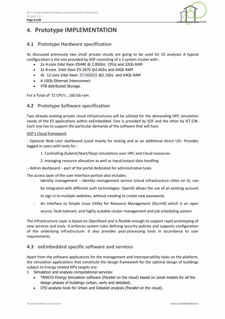
As discussed previously two small private clouds are going to be used for ES analyses A typical configuration is the one provided by SOF consisting of a 3 system cluster with :
2x 4-core Intel Xeon E5440 @ 2.85Ghz CPUs and 32Gb RAM
2x 8-core Intel Xeon E5-2670 @2.6Ghz and 64Gb RAM
4x 12-core Intel Xeon E7-4830V3 @2.1Ghz and 64Gb RAM
A 10Gb Ethernet Interconnect
4TB distributed Storage.
For a Total of 72 CPU’s , 160 Gb ram.
4.2 Prototype Software specification
Two already existing private cloud infrastructures will be utilized for the demanding HPC simulation needs of the ES applications within eeEmbedded. One is provided by SOF and the other by IET-CIB. Each one has to support the particular demands of the software that will host.
SOF’s Cloud framework
- Optional Web User dashboard (used mainly for testing and as an additional direct UI)– Provides logged in users with tools for :
1. Controlling (Submit/Start/Stop) simulations over HPC and Cloud resources.
2. managing resource allocation as well as input/output data handling
– Admin dashboard – part of the portal dedicated for administrative tasks
The access layer of the user interface portion also includes: - Identity management – identity management service (cloud infrastructure relies on it), can
be integrated with different auth technologies. OpenID allows the use of an existing account
to sign in to multiple websites, without needing to create new passwords.
- An interface to Simple Linux Utility for Resource Management (Slurm9) which is an open
source, fault-tolerant, and highly scalable cluster management and job scheduling system
The Infrastructure Layer is based on OpenStack and is flexible enough to support rapid prototyping of new services and tools. It enforces system rules defining security policies and supports configuration of the underlying infrastructure. It also provides post-processing tools in accordance to user requirements.
4.3 eeEmbedded specific software and services
Apart from the software applications for the management and interoperability tasks on the platform, the simulation applications that constitute the design framework for the optimal design of buildings subject to Energy related KPIs targets are: 1. Simulation and analysis computational services:
TRNSYS Energy Simulation software (Parallel on the cloud) based on zonal models for all the
design phases of buildings (urban, early and detailed).
CFD analysis tools for Urban and Detailed analysis (Parallel on the cloud).

D6.1 Cloud-based simulation and optimization framework Version 1.0 Page 22/26
© eeEmbedded Consortium www.eeEmbedded.eu
iTWO/LCA, iTWO/LCC (Web Applications), 5D End-to-End Enterprise Solution for Lifecycle
Analysis and Costing.
2. Authoring tools
ALLPLAN, Architectural CAD
DDS-CAD (Local Application), MEP-CAD System, 3D design system for Mechanical, Electrical
and Plumbing systems - from 2D design to 3D modelling through to the virtual building space
model. DDS-CAD MEP pro-vides the MEP Model design part for eeE which can be further
used for cost estimation and detailed CFD analysis also.
eeBACSWiz (Web Aplication), eeBACS Wizard, a prototype eeE application that allows the
BACS planner to find the correct set of templates based on KDRs in the Early Design Phase.
Based on the resulting templates, simulation, LCA and LCC analysis can be performed in later
stages of a project.
GD (Web Application), Granlud Designer, a prototype application for FM that can be used to
read main HVAC components from HVAC BIM models, add missing information by utilizing
HVAC templates and define HVAC system service areas. The main task of GD is to link HVAC
components to FM templates to define LC service life and maintenance needs
iTWO
3. Decision Support Tools
KPA, Key Point Analysis Tool, a prototype eeE application which purpose is to support the
decision making process that aims to meet intended target values and deter-mine the
different alternatives on the basis of the best possible solution(s). The visualization
(embedded in the MMNav) will enable intuitive reasoning to analyze the simulation results,
investigate the effects of design variables taking into account different KPIs and assess the
impact on different alternatives. The graphical representation will use advanced visualization
techniques to provide for fast over-view and comparison of simulation results.
Among the above applications only Simulation Applications are integrated on the cloud and their outcome along with the LCA/LCC simulations constitute the basis for the decision making process.
4.4 Energy Simulation software based on zonal models –TRNSYS (IET)
As energy simulation tool TRNSYS will be used within all use cases for analyzing the thermal behavior of the building including the operation of internal and external energy systems and main HVAC components. Regarding to the modular concept and the build-in analysis algorithms a broad variety of analysis tasks could be supported. Design alternatives are simulated on hourly or sub-hourly basis for periods of time ranging from a design day to a reference year or more. For the Urban design it concerns the analysis of the available energy resources per time, quality and quantity for optimization of the energy system architecture and resource mixture regarding energy systems and resources which are available at the building site and in the site surrounding for optimal performance. For the Early design it concerns the detailed analysis of the interaction of building/space envelope, weather conditions, user behavior, HVAC components during selected periods or on yearly basis. Caused by the early design phase a high amount of assumptions will be included.
For the Detailed analysis it concerns the detailed analysis of the interaction of building/space envelope, weather conditions, user behavior, HVAC components during selected periods or on yearly basis with embedded BACS simulations (controller, HVAC actuators/drives and sensors, rooms of the

D6.1 Cloud-based simulation and optimization framework Version 1.0 Page 23/26
© eeEmbedded Consortium www.eeEmbedded.eu
building), Figure 3. It is possible to simulate the room temperature control, relative humidity control, air-quality control (CO2) of single or multi-zones. The above ES analyses deal with the KPI estimation for various design alternatives on hourly or sub-hourly basis for periods of time ranging from a design day to a reference year or more. This type of simulation requires hundreds of thousands program execution, which do not require exchange of data each other, are arranged to the cloud nodes.
Figure 3: TRNSYS-TUD, ES application for the detailed analysis of interoperation between building, integrated energy systems, users and weather.
4.5 CFD Simulations
CFD detailed simulations are used in two design phases. 3DWind is used for the aerodynamic analysis of a building embedded in its urban environment to obtain the best building cubature (shape and orientation) regarding energy consumption indices, local wind potential for renewable energy use and natural ventilation design (as a result of the combination of the solar radiation and the wind flow) (Figure 4a). It can be used as a complementary tool to Energy Simulation applications during the urban design phase. 3DThermalCFD is used within detailed design phase for the detailed analysis of the indoor climate in buildings for the evaluation of the performance of the HVAC systems, the prediction of thermal comfort conditions and the design of special purpose ventilation, heating and cooling systems according to the geometrical design of the building (Figure 4b). 3DThermalCFD application stands as a complementary tool to the Energy Simulation applications and it is the unique tool for energy simulation in case of buildings of special use (operation theatres, clean rooms etc.) or of non-conventional geometries. Both solvers are available for Linux and MS Windows OS via command line, it is about parallel application based on the MPI protocol. There is also available a parallel version for GPUs.

D6.1 Cloud-based simulation and optimization framework Version 1.0 Page 24/26
© eeEmbedded Consortium www.eeEmbedded.eu
Figure 4a: 3DWind, aerodynamic analysis of buildings embedded in their urban environment
Figure 4b: 3DThermalCFD, detailed simulation for indoor climate The time and memory requirements for both of the above CFD simulation explode and go beyond the usual available computational facilities of a classic engineering design team. For the demanded high computing power necessary to realize a Virtual Energy Lab on the desktops of SME engineers, the involvement of cloud computing on a rental basis is the most promising solution, since cloud computing has the potential to become a major tool for scientists and engineers to access High Performance Computing (HPC) resources.
D6.1 Cloud-based simulation and optimization framework Version 1.0 Page 25/26
© eeEmbedded Consortium www.eeEmbedded.eu
5. CONCLUSIONS
The purpose of the document is to provide a description of the Cloud-based simulation and optimization framework. This work has been done within WP6 task T6.1.
The document provides an overview of use-cases and requirements described in eeEmbedded Deliverables D1.5 and D8.1 that provide the basis on which eeEmbedded simulation and optimization framework has been developed. The implementation details are described which
include hardware and software specification of the framework as well as eeEmbedded specific software currently deployed on cloud.

D6.1 Cloud-based simulation and optimization framework Version 1.0 Page 26/26
© eeEmbedded Consortium www.eeEmbedded.eu
References
1 http://docs.aws.amazon.com/AWSEC2/latest/UserGuide/concepts_micro_instances.html
2http://docs.aws.amazon.com/AWSEC2/latest/UserGuide/instance-types.html#AvailableInstanceTypes 3http://docs.aws.amazon.com/AWSEC2/latest/UserGuide/using_cluster_computing.html#concepts_cluster_compute 4 (Amazon Web Services.: http://aws.amazon.com/)
5 (Google AppEngine: http://code.google.com/intl/en/appengine/)
6 (Microsoft Azure: http://www.windowsazure.com/)
7 (Autodesk 360, available in: https://360.autodesk.com)
8 http://ises.eu-project.info/
9 http://slurm.schedmd.com/slurm.html