ee'/i/i/eb///e national dam safety program. cold … · teti t * .4nd je a 1 led .ompia #i i...
TRANSCRIPT

AD-AIOk 429 ARMY ENGINEER DISTRICT NORFOLK VA F/6 13/13NATIONAL DAM SAFETY PROGRAM. COLD SULPHUR SPRINGS DAM (INVENTOR--ETC(U)
UNCLASSIFIEDEE'/I/I/EB///EEEEEEEEEEEEEEIJIJEEEEEEEEEEEEI
JAMES RIVER SASIN
NameOf Dam: COLD SULPI4ER SPRMISLecatiem: ROCKBRIOGE COUNTY
Isvstey umbr: VA 16307
PHASE I INSPECTION REPORTNATIONAL DAM SAFETY PROGRAM
* -lossA A. L
KPfWPAWSDWsea MUONT STOUST
WOSPWOLK. VUWOMtA A2610
WA Y 001
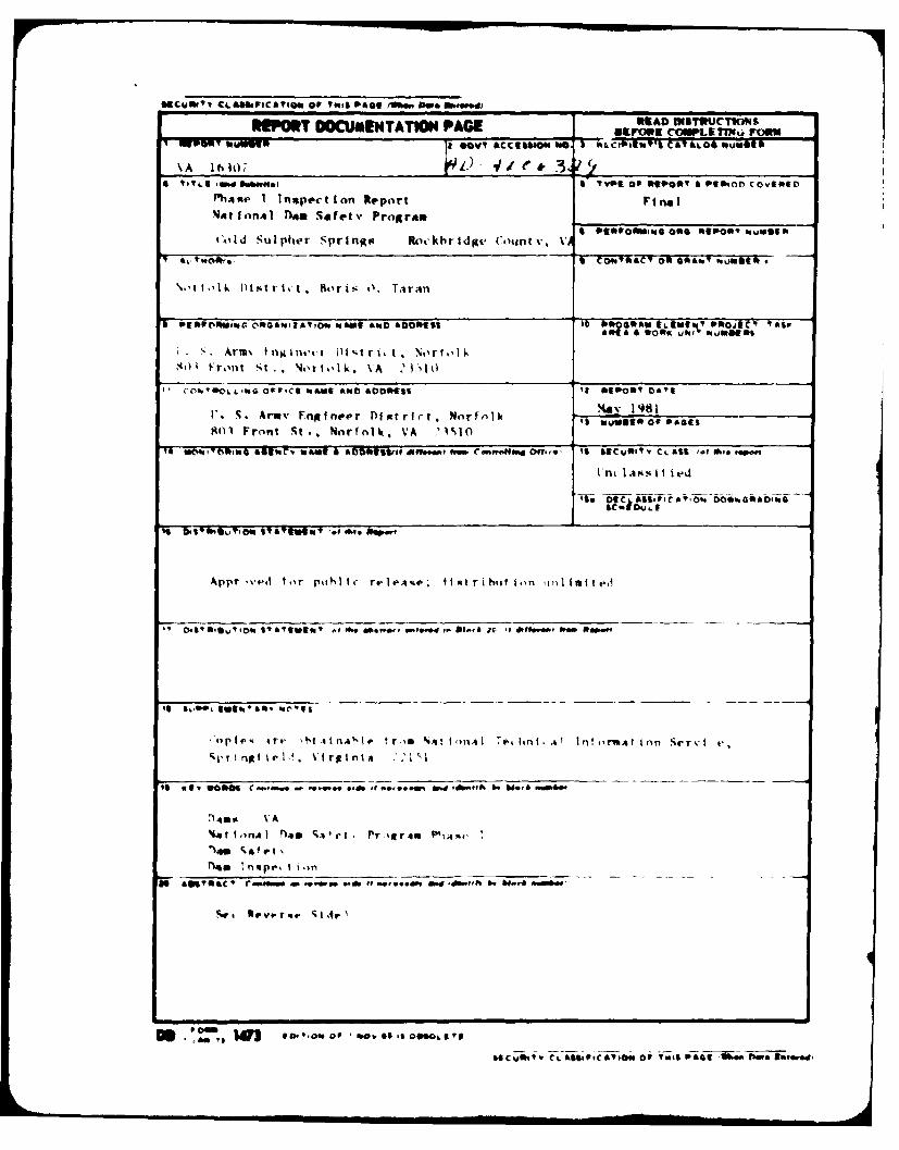
REP OPT DOCUMENTATMO PAGE _________________
Ph4eI Inspection Report Fin. iNationAl Noe Safetv Program ______________
S C GsY A t05 C O 00w SI* 'O.
s*~~Vrf uses tnin'j )jtr
iFro'nt St. Nwr I oI k. \A : 2 I Io
C0%'UeLLWG 9FICS IaNSVI 4, 010 0551
1'. S. Armv FngIneer flIpttrir. Worfnlr It IdumstoOf PAGES801 Front St., Norfnik. VA 1%10
V " V011111S atC' "oa C a Now5~ iw~ Cotttr"It~ Off,,*, It S#CUfhT CL ASS I.f 10 P. "
I nt I Asst I ted
S~~pfla *I IW ASSP'at000C00OW
Akpr ti tor p0tli I(- reAP it r I hit I on w)imitd
ST"1411 m 5'q abrgY 15 efte- 0"t.d t. Do-& ". It . 0, Rep.
41ple.- 4rr Mt~ 41 nA 'Irf tr,,m %At I on.41 7.4, hri .4 In! ormhAt ton S4'r-i v
to Re *boo C00 - 0-e..9 - ,. *. 00 If ~. .09" W..h Id f nwe&M14
'%a e t N
Noq Tnape, to
404'eaC' r ~ -e4s f~'@ Ed ff..f bf. & . 00"
Sr:: iii Re ...ti ou eSa 0505'
&evili~ CL6 0S9cYo oV IwoS VAG 0.s fe 50004, v

16.5' ~.*1,P(Altow OP ".is OlkeGIwe Poe ww.,d
1'it rsti.i nt r o Pi hi I. I A , '- Ii' v Pi i I I n a I", v ii Ro-po rt i rv 1rivpa redwtider %tool ance cclnt iI tied In Ithe tciimmn11. itile lti I Ilies Ior %At..t v
I nnsiet I .%n of im A. piiat' I qt iwi .v t I it, (I It.. i .1i ChIe IrI t Eng I nei'ru,Washi ngt tini, D. C . NO1 4. The. pistr11ome i it a I Inapet t ion ItiI t ln, if v .'~ie it I oti% I v I hi.s.' .amp tI ffc mwav lio~ h,,.Arts to attain II I e orpropertit. The Assessment of ftie gtenerA I ioni$I I I tns it f he dlam Isa hv mediipon ;4vii lAhIa 1 Av tind vi sca.* I notpi'arI tIn.-N 1u 1 ll 1 1 VC M I g A Io and1.11
anAlIyqex I nvolIvi ntg I tipogrAph 14 otqp I ag , muatisrfadac I tivent I gat I tins,tetI t * .4nd Je A 1 led .ompia #I I in-41 cv.#l 11.41I I oini are Ihvond I i' i,.)pv ol a
Phase I invest Ilat Ion. however. t he I nvextligat lon I x I Mended Co ident iI v.4n%, need f or -a iach .4 1141 fe 0.
llauod~ 11potifI# Ic telli ondi I I onsit thfir t Ie if t hie fifell inapec. ( I ton ind
al I val lable engi noeri ng Anta.~ thle PhAse I report Addiresses thelivtra~aitilfc hi .1ro I .i c. * eo Ici . * eotechti h I, ind otic-t iira 1 %acpec t % oft he (lam, The ingi netrt ng t echnlIques emplov'd give A re,%son~ahl v iaccurat viinaeqisment of the onwlt Innt o the lam. It should he reAlived th.itcertain enaineering aspect s canot te full .Inalyzed diartng a Phase II vnpet- a Ion. A~cseisment ani rined tAl fwteiiareat In t hi report In.) tide t hereqo i resient at of iddlIt ionAl I Idepa h %t tidv when ne-estarv.
'i .t-tv I report st Intc 1 itle pro tJecC I nIoritaat I on -if the .!at. ilpirt en.inces, i! I*'alsttnAg engineering data, operAtional procedutres, hydrail Ic /hyd ro logic,lit i -it tti watersthed. dam ntahlltv, vinut~ inspect ion report ind an.4axissent incliirg reqiretl remedial neAstari's.
SECURITY CL A"OIc~tC141O or TMIS P444,01,11 Doe aft..d

JAMES RIVER BASIN
NAME OF DAN: COLD SULPHUR SPRINGSLOCATION: ROCKBRIDGE COUNTY, VIRGINIAINVENTORY NUMBER: VA 16307
FUASE I INSPECTION REPORTNATIONAL DAM SAFETY PROGRAM
National Dam Safety Program. ColdSulph~r Springs Dam (Inventory NumberVA 16307), James River Basin, RockbridgeCounty, Virginia. Phase I InspectionReport.
PREPARED BYNORFOLK DISTRICT CORPS OF ENGINEERS
503 FRONT STREETNORFOLK, VIRGINIA 23510
Nay 1

j TABLE Of CONTENTSPreface *... . . . . . . . . . . .. i
brief Assessment of Dam o o . . . e o i
Overview of Dam
Section 1" PROJECT IKFRMATION .......... ... 1-1Section 2: ENGINIEERlNG DATA .. o . . . . . . . . . .. 2-1Section 3: VISUAL INSPECTION . . . . . ... . . . . 3-1Section 4: OPERATIOKAL PiOCED'hLES . o .. . . . 4-1Section 5: tiDRAUGLIC/ltyDROLOGIC DATA ..... .... 5-1
Section 6: DAN STABILITY * .. . . . . 6-1Section 7: ASSESSMENT/REMEDOAL K;S;RiS" 7 : -1
*Appendix I: Maps and DrawingsAppendix 11: PhotographsAppendix III: Field ObservationsAppendix IV: References
Acoession Pop
NTIS Gpjl .
Digt

PUFACE
This report is prepared under guidance contained in the RecommendedGuidelines for Safety Inspection of Dams, for Phase I lnvestigations.Copies of these guidelines may be obtained from the Office of the Chiefof Engineers, Washington, D.C. 20314. The purpose of a Phase I investi-gation is to identity expeditiously those dams which may pose hazards tohuman life or property. The assessment of the general condition of thedam is based upon available data and visuat inspections. Detailed in-vestigation and analyses involving topographic mapping, subsurfaceinvestigations testing, and detailed computational evaluations are beyondthe scope of a Phase I investigation- however, the investigation isintended to identity any need for such studies.
In reviewing this report, it should be realized that the reportedcondition of the dam is based on observations of field conditions at thetime of inspection along with data available to the inspection team. Incases where the reservoir was lowered or drained prior to inspection, suchaction, while improving the stability and safety of the dam, removes thenormal load on the structure and may obscure certain conditions whichmight otherwise be detectable it inspected under the normal operatingenvironment of the structure.
It is important to note that the condition of a dam depends onniomerous and constantly changing internal and external conditions, and is,vclutionary in nature. It would be incorrect to assume that the presentcondition of the dam will continue to represent the condition of the damat some point in the future. Only through continued care and inspectioncan there be any chance that unsafe conditions be detected.
Phase 1 inspections are not intended to provide detaiied hydro'og.canu hydraulic A n i,se . In accordance with the established guidelines,the spillway design flood is based on the estimated "Probable Max~mL=Flood" for the region (flood discharges that may be expected from themost severe combination of critical meteorologic and hydrologic conditionsthat are reasonably possible), or fractions thereof. Because of themagnitide and rarity of such a storm event, a finding that a spillway
; not pass the design flood should not be interpreted as necessarilyP", ng a highly inadequate condition. The design flood provides ameasule of rc.lative spillway capacity and serves as an aide indetermining the need for sore detailed hydrologic and hydraulic studies,,onsidering the size of the dam, its general condition and the downstreamdamage potential.

PHASE I REPORTNATIONAL DAN SAFETY PROGRAN
BRIEF ASSESSME T OF DAM
Mane of Dam: Cold Sulphur SpringsState: Virginia
Location: Rockbridge CountyUSGS Quad Sheet. Millbore, VirginiaStram: Cold Sulphur Springs BranchDate of Inspection: 27 May 1981
Cold Sulphur Springs-Dam in an earthfill structure approximately250 feet long and 26.1 feet high. The dam is owned and maintained byMr. John C. Goodbar, Mr. Willis F. Edwards, and Mr. Harold F. Edward.The dam is classified as a smail size dam with a significant hazard
classification. The principal spillway is a concrete open channellocated at the right abutment. The emergency spillway is a low arealeft of the dam used as an access road. The reservoir is used for
recreation.
Based on criteria established by the Department of the Army,
Office of the Chief of Engineers (OCE), the Spillway Design Flood(SDF) is the 100-Year Flood. .The spillway is capable of passing 13
percent of the PHF without overtopping the crest of the dam. The SDFwill overtop the dam by 0.92 feet, reach an average critical velocityof 4.5 feet per second, and pass over the crest of the dam for 1.5hours. Overtopping velocities are not considered detrimental to the
dam. The spillway is adjudged as inadequate, but not seriouslyinadequate.
The visual inspection revealed a seep on the downstream slope withevidence of piping. Also a shallow 12-foot wide depression was noted40 feet right of the seep. It is recommended that a geotechnical
engineering firm be retained within six months to evaluate thepossible piping and the cause for the 12-foot wide depression. It isalso recomended that within 12 months a regular maintenance programbe initiated to maintain the integrity of the structureand correct
those deficiencies listed in Section 7.2.
Submitted By: Approved:
Original signed by: Original signed by:
Carl S. Anderson, Jr. Ronald E. Hudson
CARL S. ANIDERSON, JR., P.E. RONALD E. HUDSONActing Chief, Design Branch Colonel Corps of Engineers
Commander and District Engineer
Recomended ByOriginal signed byJAMES A. WALSH
, JACK G. STARR, P. E.
Chief, Engineering Division
ii

DAM
RESERVOIR
OVERALL VIEWSCOLD SULPHUR SPRINGS DAM
27 MAY 1981

SECTION I
PROJECT INFORMATION
1.1 General:
1.1.1 Authority: Public Law 92-367, 8 August 1972, authorizedthe Secretary of the Army, through the Corps of Engineers to initiatea National Program of Safety Inspections of Dams throughout the UnitedStates. The Norfolk District has been assigned the responsibility ofsupervising the inspection of dams in the Commonwealth of Virginia.
1.1.2 Purpose of Inspection: The purpose is to conduct a Phase 1inspection ccording to the Recommended Guidelines for.SafetyInspection of Dams (Reference 1, Appendix IV). The mainresponsibility is to expeditiously identify those dams which may be apotential hazard to human life or property.
1.2 Project Description:
1.2.1 Daand Appurtenances: Cold Sulphur Springs Dam is an
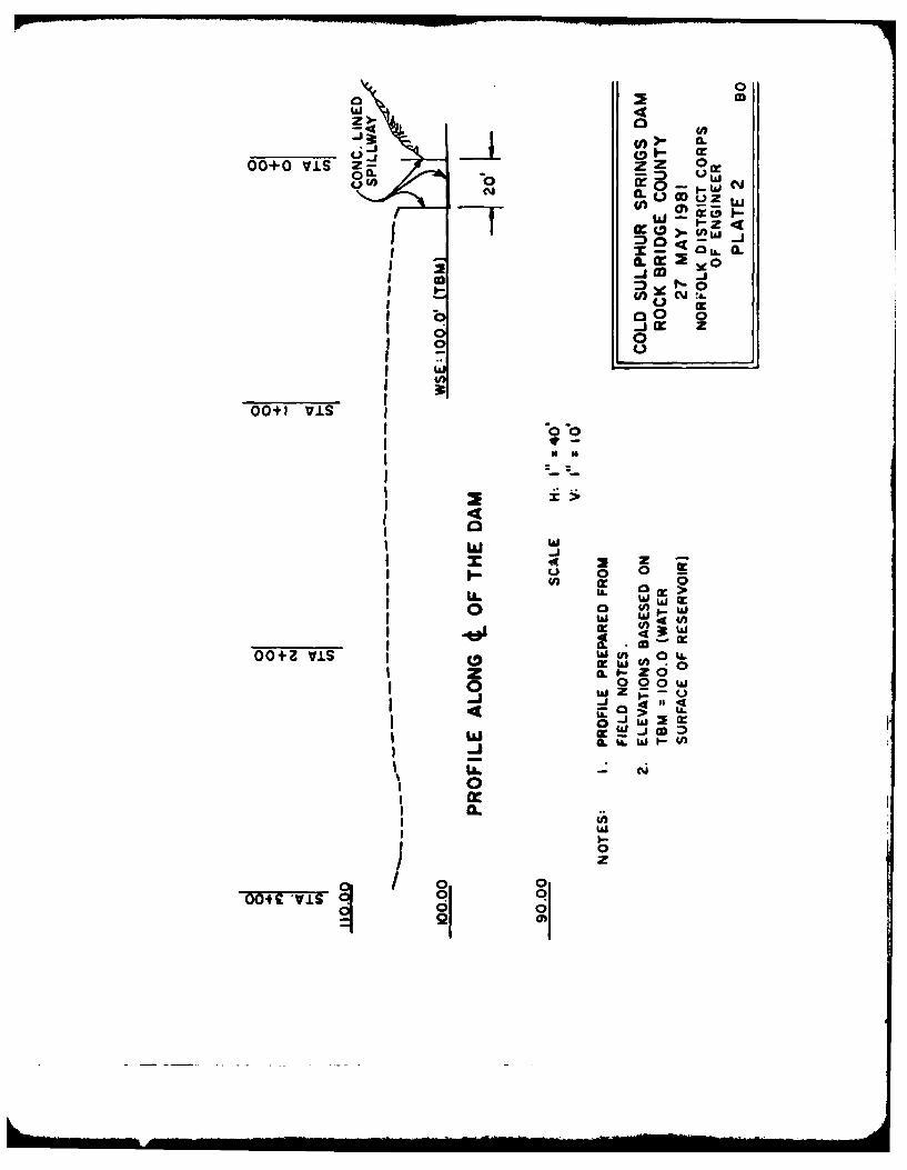
earthfill structure approximately 250 feet long and 26.1 feet high.The crest of the dam is 14 feet wide at elevation 1449.0. Theupstream slope is approximately 2 horizontal to I vertical (2H:IV) andthe downstream slope is 2.5H:IV.
Originally a small concrete dam was built on this site. This dam nowserves as the core for the earthfill structure. According to Mr.Goodbar, the dam is keyed into the underlying shell rock. It is
unknown whether or not there is a drainage system. There are no
foundation drain outlets. There is no slope protection.
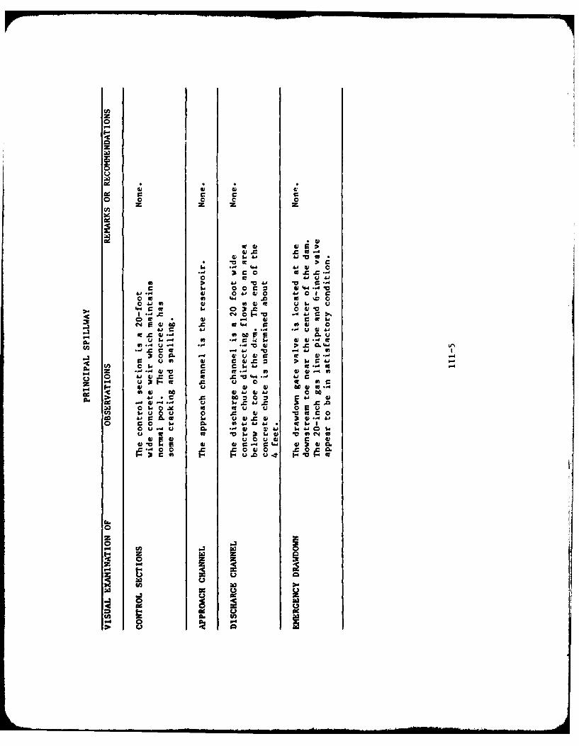
The principal spillway is a concrete open channel located at theright abutment. The spillway is 20 feet wide and the crest elevationis 1443.0. A concrete chute with wing walls directs the flow to astilling basin below the toe of the dam.
The emergency spillway is an open area left of the dam used as anaccess road. The crest width is 50 feet and is at elevation 1448.0.
A 20-inch gas line pipe passes through the dam at low levelenabling the reservoir to be drawn down. A 6-inch gate valve is
located at the downstream end of the pipe at elevation 1424.0.
1.2.2 Location: Cold Sulphur Springs Dam is located about 0.5 mileswest of the intersection of State Routes 780 and 39 in RockbridgeCounty on the Cold Sulphur Springs Branch of the Calfpasture River.
1.2.3 Size Classification: The dam is classified as small size asdefined in Reference 1 of Appendix IV.
I-1

1.2.4 Hazard Classification: The dam is located upstream of twohomes and a lum-ber mill. Should a dam failure occur, lives could belost and property damage incurred. Therefore, the dam is given asignificant hazard classification, as defined in Reference 1, AppendixIV. The hazard classification used to categorize a dam is a functionof location only and has nothing to do with its stability orprobability of failure.
1.2.5 Ownership: The dam is owned by Mr. John C. Goodbar, Mr. WillisF. Edwards and Mr. Harold F. Edwards.
1.2.6 Purose: Recreation
1.2.7 Design and Construction History: The dam was designed with theguidance of the county agent from the extension service of VirginiaPolytechnic Institute and constructed by Mr. John C. Goodbar and Mr.W. Edwards. The dam was completed in 1960. There is no informationon the concrete dam.
1.2.8 Kormal Operational Procedures: Operation of the dam isautomatic with water flowing through the principal spillway when thereservoir rises above elevation 1443.0. Flows through the emergencyspillway occur when the reservoir rises above elevation 1448.0.
1.3 Pertinent Data:
1.3.1 Drainage Area: The dam controls a drainage area of 1.94 squaremiles.
1.3.2 Dischargest Dam Site: The maximum flood observed was duringTropical Storm Camille in 1969. Flow was estimated to be 3 to 4 feetin the principal spillway.
Pool level at crest of dam
Principal Spillway .............. ......... ..... 882cfsEmergency Spillway .............. .... ............. 1357cfs
1.3.3 Dam and Reservoir Data: Pertinent data on the dam andreservoir are shown in the following table:
TABLE 1.1 DAM AN~D RESERVOIR DATA
_ Reservoir. . .
Elevation Capacity-
feet Area Acre Watershed, Length,Ite Ml Acres feet Inches fe
Crest of Dam 1449.0 11.5 145 1.4 2000Emergency Spillway Crest 1448.0 10.0 130 1.3 1900Principal Spillway Crest 1443.0 6.4 64 0.6 1130Streambed at Down-
stream toe of dam 1422.9+ - - -
. . . . . ..r l- 2# .. .. . " . . . .. . I l l i

SECTION 2
ENGINEERING DATA
2.1 Desirn: The earthfill dam was designed with guidance from thecounty extension agent of Virginia Polytechnic Institute. However,there is no available design information. There is no information onthe old concrete dam. However, it is described as a concretestructure across the stream with a reccangular notch for a principalspillway.
2.2 Construction: The dam was constructed by Mr. John C. Goodbar andMr. W. Edwards, two of the present owners. The dam was completed in1960. According to Mr. Goodbar, the 20-inch gas pipe, serving as al level drain, was placed in the rectangular spillway of theconcrete dam. The downstream end of the spillway was plugged with abulkhead (headwall) and the dam covered with fill. The embankment wasconstructed with a "clay type" soil borrow.ed from the reservoir. Adecomposed shale was placed on the embankment for protoction. Nofoundation drains were constructed. The foundation f the concretedan and principal spillway are keyed into the shale bedrock. There isno construction information on the old concrete dam.
2.2 Evaluation: There is insufficient information to evaluate thefoundation condition and the embankment stability.
2-1

SECTION 3
VISUAL INSPECTION
3.1 Findinas:
3.1.1. General: The results of the 27 hay 1981 inspection arerecorded in Appendix Il. At the time of the inspection, the weatherwas overcast and the temperature was about 70*F. The pool elevationwas approximately 1443 feet lsl or about normal pool. The tailvaterelevation was at 1422.9 feet usl. There are no known past inspection
reports available.
3.1.2 Dag: The general soil condition was dry. There are no signsof surface cracks, unusual movement, or misalignment. There issurface erosion on the upstream slope probably due to pedestriantraffic and aggrevated by surface runoff. Also, on the downstreamslope, there is a depression, approximately 2 feet in depth caused bya seep flowing at a miniumr rate of 1.1 gpm. A probing in the seepindicated a very soft material to a depth of 2 feet. The seep islocated approximately 4 feet in elevation directly above the 20-inchgas pipe serving as a low level drain. The seep is possibly caused byleakage along the pipe where the bulkhead plugs the rectangularspillway of the concrete dam. According to Mr. Goodbar, the seepagestarted shortly after the construction of the earth embankment and hasnot increased. There is an additional depression, about 40 feet tothe right of the seep. It is about 12 feet in diameter and 1.5 feetin depth.
There is an animal burrow approximately 30 feet left of the principalspillway and halfway down the dovnstream slope. It is about 8 inchesin diameter and greater than 6 feet in depth.
There are trees and shrubs covering both the upstream and downstreamslop*&. The trees are as large as 12 inches in diameter.
3.1.3 Principal Spillway: The control section is a 20-foot wideconcrete weir which maintains normal pool. The concrete has somecracking and spalling. The approach channel is the reservoir. Thedischarge channel is a 20-foot wide concrete chute directing flow tothe tailwater beyond the dovnstream toe of the dam. The end of theconcrete chute is undermined about 4 feet on the right side. This wasprobably due to an eroded channel down the right side of the principalspil lway.
3-1

3.1.4 Drawdown Ouitlet Works: The intake structure is submerged andnot observable. The drawdown gate valve is located at the downstreamtoe at about station 1+00 as shown on Plate 3. The 20-inch gas linepipe appears to be in satisfactory condition.
3.1.5 E.i-rvncy Spillwav: The control section is in natural grounto the left of the dan. A Fravel acc.'.s road passes through thespillway. The approach channel is a gravel road descending inelevation and connecting to the immediate reservoir slope. Thedischarge channel is a gravel road descending in elevation whichallows flows to pass to the downstream toe area.
3.1.6 Instrumentation: There is no instrumentation on the dam.
3.1.7 Reservoir Area: The reservoir slopes are moderately steep andheavily wooded. ihere are no signs of reservoir slope failures orshoreline erosion. No debris was observed in the reservoir. There isno available information pertaining to sedimentation.
3.1.8 Downstream Channel: The downstream channel is narrow withmoderately steep and heavily wooded slopes. There are some large rocksand trees in the channel directly below the dam. Two homes arelocated about 0.5 miles downstream of the dam. A lumber mill islocated approximately one mile downstream.
3.2 Evaluation: Overall, the dam appears to be in good condition.However, the seep on the downstream slope, and the depression causedby this seep are sign of possible piping. This problem and the12-foot wide depression 40 feet right of the seep are furtherevaluated in Section 6. In addition, the inspection revealed certainpreventative maintenance items which should be scheduled as part of anannual maintenance program. These are:
a. The trees and shrubs on both slopes should be cut off at theground surface. Any trees with a diameter greater than 3 inchesshould have their root systems removed and subsequent holes backfilledwith compacted material and seeded.
b. A continuous program to control vegetative growth in the
emergency spillway channel and on the embankment should be institudedas part of a regular maintenance program.
c. The animal burrow should be backfilled with compacted fill andseeded.
3-2

d. Th. eroded oaras tb. upstreem slope should be dressed witkeoipted fill and seeped.
e. A stafftgv. should be installed in che reserveir to ecardabove the top *I the dm.

U C 1 lol 4
OPt AI IOAL P! gDUll
4.1 F1i t,'rtr the mmlmeil storage pool is 1441.0 It. set. which is
the ciest (-I the pCimuapol spi l hwav. he reservoir provi41s
Srea0t.&or%, bate t passes autcauti.allv over the principal spalivay asthe reser1voit r aos above 9k*eb i t ln |t).O. water will also flab over
he eergenov p.llVke as the pop& vises ab-ve elevation 140.O. A
70- aCh gas line pipe passers th:1 h the da at to level Sn4 fait&
the da at ihe dotnittrW toe of ih dia. A *-inct vlvv located mn
t1e dwnst I eaf nd of trhe pipe is ova aI ablI to lowr the r*64e1rvolrhelo ormal poe;.
... ts rtenance there is no regular mintenanice prorm for Cold
Sulphur Spring& Dam.
ob.) W Us At presernt tier. there i Cw' barning system or
evacuation p| Cold Sulphur Sprivhs.
6 . va!%,at I nn the dam doe& not reeqlfire an elaborate oprational
amd maintenance program, Uwvr. a regular maintenance program,comp lete %irh documentation. Should be developed. It is rcOm deed
that a fIrsal einrgency procedure be prepared and furnished to all
opertetin personnel. This should include
a. Rob to operate the dam during an ewrgency.
b. Who to notify, including public officials, in case evacuation
tram the downstream area is necessry.
*!

SECTION 5UVUkAULIC/NVDDOLOGlC DATA
5.1 Deaa None were available.
S.2 9 l lr |-g inlo so 13 were available.
5.3 Floa4t [nersence The maaimum flood observed was during Tropical
Storm Camle in 1969. when ilt 3 to 4 feet in depth passed throughthe principal spillway.
5.4 flood Potential: The 100-year flood, 1/2 PH?, and PH? weredeveloped and routed through the reservoir by use of the REC-IOcomputer program (Reference 2, Appendix 1%) and appropriate unithydrograph . precipitation and storage - outflow data. Clark'sTc and I coefficients for the local drainage area were estimated frombasin characteristics. The rainfall applied to the developed unithydrograph was obtained form the U. S. Weather bureau Publications(References 3 anJ 4. Appendix IV).
5.5 IeservoirRi.tulations: Pertinent dam and reservoir data areshown in Table 1.1.
Water passes automatically over the principal and emergency
spillway* as the reservoir rises above elevations 1443.0 and 1441.0,respectively.
The storage curve was developed based on areas obtained from aU. S. Geological Survey Quadrangle Nap. Survey data taken during theinspection was correlated to the Millboro, Virginia Quadrangle Hap tohelp develop area storage data. Rating curves for the principalspillway, emergency spillway, non-overflow section and drawdownfacilities were developed by hand. In routing hydrographs through thereservoir, it was assumed that the initial pool level was at theprincipal spillvay crest (elevation 1443.0).
5.6 Overtopping Potential: The probable rise in the reservoir andother pertinent information on reservoir performance is shown in thefollowing table:
5-1

TABL! 5.1 RESERVOIR PERPY0P4A1CE
Normal 100 1/Item flow year 1/2 PRY FlIF 2/
Peak flow. c.f.s.Inflow 2432 6772 13545Outflow 2432 6772 13545
Maximum elevationft. mSl 1443.0 1449.92 1457.05 1454.3A
Non-overflow sectionelevation 1449.0Depth of flows, ft 0.92 3.05 5.36Duration, hrs. 1.50 4.75 5.00
Velocity, fps. 3/ 4.50 8.10 10.85
Tailvater elevation 1422.9. - - -
1/ The 100-Year Flood has one chance in 100 of occurring in any given year.2/ The PiF is an estimate of flood discharges that may be expected from themost severe combination of critical meteorologic and hydrologic conditions thatare reasonably possible in the region.
3/ Critical Velocity
5.7 Reservoir Emptying Potential: A 20-inch gas pipe with a 6-inch valve at
the downstream toe of the dam (elevation 1423) is available to devater the
reservoir. The low level outlet will permit a withdrawal of about 4 cfs withthe reservoir at the crest of the principal spillvay (elevation 1443.0) andessentially devater the reservoir in approximately 19 days. This is equivalent
to an approximate drawdown rate of 1 foot per day based on the hydraulic height
measured from normal pool divided by the time to devater the reservoir.
5.8 Evaluation: Based on the size (small) and hazard classification
(significant), the recommended Spillway Design Flood is the 100-year flood tothe 1/2 PMF. Because of the risk involved, the 100-year flood has beenselected as the SDF. During the SDF, the crest of the dam will be overtopped
by 0.92 feet for a maximum 1.5 hours and reach an average critical velocity of
4.5 feet per second.
Conclusions pertain to present day conditions and the effect of future
development on the hydrology has not been considered.
5-2

UCTION 6
DAN STABILITY
6.1 Foundation and Abutment There is no detailed information available on
the foundation condittons. The dam is located within the Valley and Ridgephysiographic province of Virginia wtich is underlain by the brallierformation of the middle devonian system. The Brallier Formation is composed
of this. regularly bedded, fissle to subfissle, micaceous, light gray to
brown to olive drab shales, siltstones. and very fined grained sandstones.The sandstones are commonly well jointed and some isolated fissle black
shale haa been found. Deformation was intense in the area and smalloverturned folds and low angle thrust faults are widespread. According to
Nr. Goodber, the old concrete dam is keyed into firm shale bedrock. Thereis no drainage syste. The foundation is considered stable and impervious.
6.2 In~aLe
6.2.1 _Nterialz There is no detailed information available on the nature of
the embankment materials. The only known information is that the borrow
area was located in the reservoir area, and the soil was a "clay type"material. A decomposed shale was placed on the embankment for protection.The area soils are generally alluvial low plastic silts (NL) and silty
clays (CL). The nature of the embankment materials is considered to be
homogeneous.
6.2.2 stabij4u, There are no available stability calculations. The dam
is 2*.1 feet high and 14 feet wide. A gravel access road traverses thecrest of the dam. The upstream slope is 2H:IV, and the downstream slope is2.SN:IV. The dam is subjected to sudden drowdown because the approximatereservoir drowdown rate of 1.0 foot per day exceeds the critical rate of 0.5feet per day for earth dams. The existing pool is approximately maximumcontrol storage pool which is the crest of the principal spillvay.
According to the guidelines presented in DesijLn of b-all Dams U.S.Itarragn. of ThS In r.ior. bureau t Rc¢lamsastion for small hamogeneousdams, with a stable foundation, subjected to a drowdown and composed of lowplastic fines (ML. CL), the recommended upstream slope is 3W:IV and thedownstream slope in 2.SN:IV. The recomended width is 15 feet.
6.2.3 jjsic Stablitv; The dam is located in Seismic Zone 2. Therefore,
according to the Reccoamned Gpidelines for Safety -Inspectin of Den, the
dam is considered to have no hasard from earthquakes provided static
stability conditions are satisfactory and conventional safety margin exist.
6.3 91gju~jnj. There is insufficient information to adequately evaluate
the stability of the dam. The visual inspection revealed no apparent
6-1

instability of the upstream slope, but revealed potential problems on the
downstream slope. There is a seep with potential piping located above thelow level outlet pipe. Also, there is a shallow 12-foot wide depression40 feet right of the seep. Based on bureau of Reclamation guidelines, thedam has an adequate downstream slope, but an inadequate upstream slope andcrest width.
The major stability concern is when the upstream slope is subjected to asudden dravdown. However, the embankment has a concrete core to prevent atotal breach of the embankment and the width is not seriously inadequate.Also, the visual inspection revealed no apparent instability of the upstreamslope. Therefore, the embankment is considered stable and no stabilitycheck is required.
The seep and possible piping does threaten the integrity of the dam. Also,the 12-foot wide depression warrants concern. A geotechanical engineeringfirm should be retained within six months to evaluate the possible pipingfram the seep on the downstream slope and also the 12-foot wide depression.
Overtopping flows are not considered deterimental. The velocity is lessthan 6 fps, the effective eroding velocity for a vegetated earth embankment.
6-2

SECTION 7
ASSESSMENT/REMEDIAL MEASURES
7.1 Dam Assessment: There is insufficient engineering data to evaluate thefoundation condition and the embankment stability. The visual inspectionrevealed a seep with possible piping on the downstream slope, and depression40 feet right of the seep. There is no emergency operation and warning planor a regular maintenance problem. However, the dam is in good condition and
a stability check is not required.
Corps guidelines indicate the appropriate spillway design flood is the
100-year flood. The spillway will pass 13 percent of the PMF withoutovertopping the dam. The SDF will overtop the dam by 0.92 feet for amaximum 1.5 hours and reach an average critical velocity of 4.5 fps. Theovertopping velocities are not considered detrimental to the embankment.The spillways are adjudged as inadequate but not seriously inadequate.
7.2 Recommend Remedial Measures: It is recommended that a geotechnical
engineering firm be retained within six months to evaluate the possibilityof piping at the seep on the downstream slope and the cause for the 12-foot
wide depression. Also, an annual maintenance program should be initiatedwithin 12 months to maintain the integrity of the structure. The inspection
revealed the following maintenance items that should be scheduled by the
owner during the regular maintenance program:
a. The trees and shrubs on both slopes should be cut off at the ground
surface. Any trees with diameter greater than 3-inches should have theirroot systems removed and subsequent holes backfilled with compacted materialand seeded.
b. Dress the eroded areas on the upstream slope with compacted fill andseed.
c. A continuous program to control vegetative growth on the embankment
should be instituted as part of a reguatr maintenance program.
d. The animal burrow, 30 feet left of the principal spillway and
halfway down the downstream slope, should be backfilled with compacted fill
and seeded.
e. A staffgage should be installed in the reservoir to extend above the
top of the dam.
7-I

APPENDIX I
IMAPS AND DRAW'INGS

-IT-,'T1"E'IF RIVER
if~e
- -. MI*;. I.~0
_ ~\Opp
V,,
I,'N.
Tali I g Ponds
-Po
4
I.
,,*-
~5 ~) IBORO QUADRANGLE
SCALE 124000 1 IE .-
lOG lo mw WWI0 w00 oo MW0 700 rr
CONTOUR INTERVAL 40 FEET-* NATIONAL GEODETIC VERTICAL DATUM OF 1929 -~I-->~~~X v I-
* -x w
0
w coza
I&II4
00+0 vis Z 0c
V) 0
rr 0J
CL . 4 OI 0.
0 -j
0o 0
00+1 v.LS I
-0,
0 0
LL. 0JUJI0 V) I.-
(nw
00+a VIS W, OILA
0 ~~ w Z~ !- o
-J -J 41 4I
w CLILWIU
0
0= o0
zog

0
j us-3i414 !oil
it
I 't.
II
'I
@ all
0
! 4.!,a" "
1o
'I

APPENDIX 11
PHOTOC RAPH S

PHOTO #! CREST OF DAM
PHOTO #2 UPSTREAM FACE

PHOTO 43 THE SPILLWAY
PHOTO #4 ERODED /UNDERCUTAREA AT DISCHARGE ENDOF SPILLWAY

PHOTO #5 6-INCH GATE VALVE ON20-INCH RESERVOIRDRAIN PIPE
PHOTO #6 INTERCEPTED FLOWFROM SEEP / BOIL ONDOWNSTREAM FACE OF DAM
APPENDIX III
FIELD OBSERVATIONS

.1v~o
4-
44 *~p. *~ -4
0.. a
beM -NC~is *~
be C**1beUC Iibeo I.-oLI C
0 V be* * I-.
a
C 0'abe be
beS Ube
be NSI
C be - I..C N be *~ N
be U A
LIbe 0 - I-
-is *j -
Cs Ct * -
5 5 ~Ll -U* .*d -4 C
*-- 4 I.
A Ii.CP1 01
4 54
bebe C
C Uo
- U CI' CS
C - S C
zC
eNj .1 be- S
- -. 4
Co be
be K-' U 5 be
3 ~ .2 a'C U S be
- C a' U
j ~ * ~I i

FA .0 a
I-.~~-0 Id S L * I S
I C V o a C V u
16 u a v2 c4aS SI I SbS ... aSD
ot rw~ CL C cA-
.C Sf
c tow.. 0e'. ~ W
1& 41& j J S L
K w
S.C~~~I le CA C b.4' 'J.
6. 0. 0 Ckc c c40S 12 40IA aAC C C~ 9)
-. u U a-mA SI "DS C
Go to CII-Af a CU aVS orS 64 ~Wm2~~ . C S U I U W S I .d DCL a
0 Id ... a.aC a c 0 l
SD wbU zS *..i&'. AL -IU C vC1a rSD) 3s c CC UWSDI 6 .l a C cD &J C
vIS A c" 0- soUSIU .SI.w 0 A cO~~~ 0I SI . V v I 4.cA V S C V W
Sd b. ~. Oi* Id 0 VSD 1 4 SWI a -IOSWSS SdI a
0c -C-
me b.
-C-c
0 to
Id r1a-a ~ m~ ~ix

4. 60 I.. 2- 31 to C
II w V C
A. 31 ic C w -i4 c c
I. ;~ C U 1
V jg
IL~ ~ ~ ~ aCC . 0Zx
Ik..
b. V' C 15.4 U v 41c d O
C' C 06 C b.- 'd C IL 41.
*uur ".IL
6. 4 4.b %dC Vf
40 .C It 41
*~~ U it~D40.
C0 *a 41 4) CdW ,
I- 4w0 4j 16.D.I.. 41 .IU 4 U' *a> S. 40 - W, bf 5 I..~44
U) 3' )S a %d:I uv.0I
US 1., a4~b Sd * C U~-C. U . vf c. v..
UId 0 0 A w' v aV C5 c o I C c cw
''I. 6WU 14 a- - C IL5
aa
- U)
?A'-

U3 c
a- %W0- C
Z ~ 0 ... 4A
~*U IVC U
CA Cu *itU
cc 44O9)(A a a w
0.4
4 -4
z *v
o 4
U) 4)I.A
Pd I.w
ho
CW
0z
0>
s0 0 0o 0 0 di 04
10 44 .0 0
:0. .0 lw 0 3 v*
C14010 . 1 . 0ol 0 4).- a e s
be be a N wr 0410 1
00 C 41 -4 vf
a d0 -4 0 00,a 0 > I IL-0 1 0 C 0 0J0 ~ b0..d
0 0 0 0w sUaO-Ia. .z IV .. 00 0)
U 00 01it0
eeUO 0h 0 bea. -ce. 1. 0. 0061=
wU~ Om to o u J be4 0b61 0 0 C .~e 0) c 0
00~~ ~ ~ A0v w VC 3 v0 CL j " " 0.
o u - 3 j j0s
w- r - 624
00z=
0
U

A0
c r_ 4) 91 0 0A0 9 c.0m bl 0 4
0 2 0 0 c-
In 41 ~cc a-
4,4
= 44J C w
* 0 0)-0 w 0) 4 c
a *00 00) -1 0
wW. 000 v ~ C C)
0w 0 -03Aj . v 44.4 * 0
-.4 C -4 0 w WCL41%4C .,d4 0 4a .
u 9:4) 9 j 0 C *0z :00 - 0 91 C) A .j -0 '-
2 O $I $ x 0 0 0-O
00)00 41 1 &4). OL
0

sd
V U
'-I
CKC
0 *0
w 4) 4144J4
Do00
UU
C) * b-
Di

0
m 0 o 0 1
P4 ~ ~ id .4-'4
v V "
0 1
z-

0
-4w
0
;1
31 3 -4 C:
$4 u0 4 w C c .,
CA 4
'1 .14.0 rJ 461
In Wi IV Ut
r u 4-) ccu0.4 r-.4 *:* 0 .
.C 41 0 UG) CU no, Uo OCW~UW
5.-1 C V 004. 9)tv c
0 A l.~aCU v *1 41
C.
w04
1-4
Z E 00
ccf- M P-P4 1.4 ) FM
- .01. .
APPENDIX IV
REFERENCES
APPENDIX IV
REFERENCES
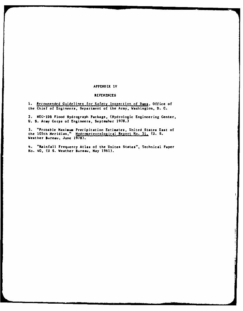
1. Recommended Guidelines for Safety Inspection of Dams, Office ofthe Chief of Engineers, Department of the Army, Washington, D. C.
2. NEC-IDB Flood Hydrograph Package, (Hydrologic Engineering Center,U. S. Army Corps of Engineers, September 1978.)
3. "Probable Maximum Precipitation Estimates, United States East ofthe 105th Meridian," Hydrometeorological Report No. 51. (U. S.Weather Bureau, June 1978).
4. "Rainfall Frequency Atlas of the Unites States", Technical PaperNo. 40, (U S. Weather Bureau, Kay 1961).

TAT;
ILME