eerroossiioonn aanndd sseeddiimmeenntt ccoonnttrrooll
TRANSCRIPT

EEErrrooosssiiiooonnn aaannnddd SSSeeedddiiimmmeeennnttt CCCooonnntttrrrooolll FFFiiieeelllddd GGGuuuiiidddeee fffooorrr CCCooonnnssstttrrruuuccctttiiiooonnn IIInnnssspppeeeccctttiiiooonnn
JJJuuulllyyy 111,,, 222000111000

Table of Contents
Abbreviations....................................................................... 1 Introduction......................................................................... 2 Dry-Erase Inspection Notes Sheets……............................. 5 Document Review............................................................... 9 Photo Logging Procedure................................................... 12 Understanding the ESC System......................................... 14
Avoiding Sensitive Areas..................................................... 15 Temporary Erosion Control Seeding.................................. 17 Sod....................................................................................... 19 Mulch................................................................................... 21 Soil & Mulch Binders.......................................................... 23 Erosion Control Blanket...................................................... 25
Turf Reinforcement Mats.................................................... 27 Perimeter Erosion Barrier................................................... 29 Perimeter Vegetated Buffer................................................ 31 Temporary Ditch Checks..................................................... 33 Aggregate Ditch Checks...................................................... 35 Storm Drain Inlet Protection............................................... 37
Diversion Dike………............................................................ 39 Sediment Removal from Dewatering Operations............ 40 Temporary Pipe Slope Drain............................................... 42 Outlet Protection................................................................. 44 Temporary Sediment Basin………....................................... 46 Temporary Sediment Trap………......................................... 48
Protect Existing Vegetation & Natural Features……........ 49 Stockpile Management....................................................... 50 Stabilized Construction Exits.............................................. 52 Tire Wash Station ............................................................... 53 Temporary Concrete Washout Facilities............................ 55 Construction Site Management......................................... 59
Material Delivery & Storage................................................ 60 Solid Waste Management.................................................. 61 Vehicle & Equipment Fueling, Cleaning & Maintenance.. 62 Extended Work Cessation/Shutdown................................ 64 NTU Water Columns............................................................ 67 Reporting & Resolving Deficiencies…................................ 68
EZ BMP Selector.................................................................. 71 Quick Reference.................................................................. 72 Acknowledgements............................................................. 73
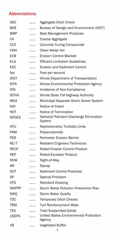
Abbreviations
ADC ....... Aggregate Ditch Check
BDE ....... Bureau of Design and Environment (IDOT)
BMP ....... Best Management Practices
CA ....... Coarse Aggregate
CCC ....... Concrete Curing Compounds
CWA ....... Clean Water Act
ECB ....... Erosion Control Blanket
ELG ....... Effluent Limitation Guidelines
ESC ....... Erosion and Sediment Control
fps ....... Feet per second
IDOT ....... Illinois Department of Transportation
IEPA ....... Illinois Environmental Protection Agency
ION ....... Incidence of Non-Compliance
ISTHA ....... Illinois State Toll Highway Authority
MS4 ....... Municipal Separate Storm Sewer System
NOI ....... Notice of Intent
NOT ....... Notice of Termination
NPDES ....... National Pollutant Discharge Elimination System
NTU ....... Nephelometric Turbidity Units
PAM ....... Polyacrylamide
PEB ....... Perimeter Erosion Barrier
RE/T ....... Resident Engineer/Technician
RECP ....... Rolled Erosion Control Product
REP ....... Rolled Excelsior Product
ROW ....... Right-of-Way
RR ....... Riprap
SCP ....... Sediment Control Practices
SP ....... Special Provision
STD ....... Standard Drawing
SWPPP ....... Storm Water Pollution Prevention Plan
SWQ ....... Storm Water Quality
TDC ....... Temporary Ditch Checks
TRM ....... Turf Reinforcement Mats
TSS ....... Total Suspended Solids
USEPA ....... United States Environmental Protection Agency
VB ...... Vegetated Buffer
1

Introduction
PPurpose of This Manual The purpose of the Illinois Department of Transportation (IDOT) Storm Water Quality (SWQ) and Erosion Control Manual is to provide a technical guide containing practices for the correct installation, maintenance, inspection and compliance of storm water erosion and sediment control (ESC) for IDOT’s roadway projects. This Manual provides guidance in the form of Best Management Practices (BMPs) that will assist a Resident Engineer/Technician (RE/T) in the management of pollutants on a construction site in order to minimize the discharge of pollutants into Illinois waters. The pollutants of concern normally associated with a construction project include: Sediment from construction Chemicals used for construction (paint, concrete curing compounds (CCC), concrete washout waste)
Trash and litter Construction debris Fuels, oils, solvents used for equipment maintenance Discharges from temporary use, storage and stockpile areas
The RE/T must have a working knowledge of sources of potential pollutants on a project.
Manual Organization The manual is organized into three main sections: Erosion control practices or stabilization measures Sediment control practices (SCPs) or structural controls Construction site management, referred to as Good Housekeeping measures.
In addition, the manual contains references for further information and a section on document reviews prior to initiating construction activities.
How to Use the Manual Each BMP introduced is formatted to include the name of the practice, definition; where the practice applies; advantages and disadvantages of each practice; installation; inspection points of concern; and maintenance requirements for each BMP. Photographs and drawings are included under each BMP to aid inspection.
All construction sites that disturb 1 or more acres of land are required to obtain coverage under the Illinois Environmental Protection Agency (IEPA) National Pollutant Discharge Elimination System (NPDES) ILR10 Permit for storm water discharges from construction site activities.
2
The permit requires construction site operators to control the site discharge of pollutants in storm water from a construction site.
A copy of the ILR10 Permit and required forms can be downloaded via the IEPA website at:
http://www.epa.state.il.us/water/permits/storm-water/storm-water-forms.html
The ILR10 Permit requires the following components: Notice of Intent for permit coverage (IEPA NOI form) Bureau of Design and Environment (BDE) Storm Water Pollution Prevention Plan (SWPPP) Form 2342
Erosion and Sediment Control Plan Sheets (graphic plan) Controls to prevent discharge of pollutants from a construction site (BMPs)
Inspections by the permit holder Incidence of Non-Compliance (IEPA ION form) Notice of Termination (IEPA NOT form) Contractor Certification Statement
The SWPPP can be downloaded from IDOT’s website at: http://www.dot.il.gov/desenv/deform.html
The RE/T must become knowledgeable with the ILR10 Permit components. Failure to comply with permit conditions can result in penalties to the Department, Contractors, and individuals.
Department construction and operation activities are covered under the ILR40 Permit for small Municipal Separate Storm Sewer Systems (MS4). The RE/T should review the permit, Department policies, and familiarize themselves with those components of the ILR40 Permit that apply to a construction project. Those components are following the requirements of the ILR10 Permit, reporting illicit discharges from the construction site, and Good Housekeeping measures for proper construction site waste management.
FFundamentals of Erosion and Sediment Control (ESC) Uncontrolled erosion and sediment discharges are a violation of the Federal Clean Water Act (CWA).
As an RE/T, one of your roles is to ensure proper implementation of the ESC Plan and thereby prevent erosion from occurring and control the discharge of sediment from the job site.
Maintain all ESC BMPs and other storm water protective measures in effective operating condition.
Establish and document responsibility for the various components of the SWPPP.
3
Correct BMPs, where failure has occurred or requires maintenance, in the timeframe specified by the RE/T and in accordance with permit requirements.
Prevent mixing of clean water with sediments and other pollutants on the project.
Follow the ‘7/14’ stabilization rule in the permit (IV.D.2.a). Minimize the disturbance of existing vegetation and refer to the SWPPP for any special restrictions.
Conduct inspections every seven calendar days and after a storm event of one-half inch of rain or equivalent snowfall. Document the inspection using IDOT form BC 2259.
One-half inch rain 5 inches of wet snow Inspections must continue during the
winter months even if construction is not active.
Keep a continually updated ESC file on the construction site.
Update the SWPPP within seven calendar days of the last inspection.
File any IONs with the IEPA as specified in the permit. Issue any required Deficiency Deductions. File NOT with the IEPA when 70% perennial vegetated cover or equivalent permanent stabilization is achieved.
Keep records for three years.
Additional contact information: IDOT Erosion Control Coordinators IDOT Storm Water Committee IDOT Standard Specifications IDOT BDE Special Provisions Illinois Urban Manual
This guide focuses on evaluating the installation and inspection of BMPs. If practices differ from systems shown in the plans and are required, the RE/T should confer with a knowledgeable designer to determine an appropriate alternative design(s).
The four pages following this section (i.e. pgs. 5-8) are intended as inspection aids. These sheets have been printed on special paper so that any dry-erase marker can be used to take notes during field inspections. The topics printed on the sheets are the most common areas of concern. Notes taken on these sheets can be saved or erased for new inspection notes. In addition to the inspection field notes remember to complete the BC 2259, submit any IEPA form (e.g., ION) and update the SWPPP upon completion of inspection.
4

Slopes (13-24) Items Correct By Date Location
Ditches (13-16, 21-24) Items Correct By Date Location
Perimeter (25-28) Items Correct By Date Location
Ditch Checks (29-32) Items Correct By Date Location
5
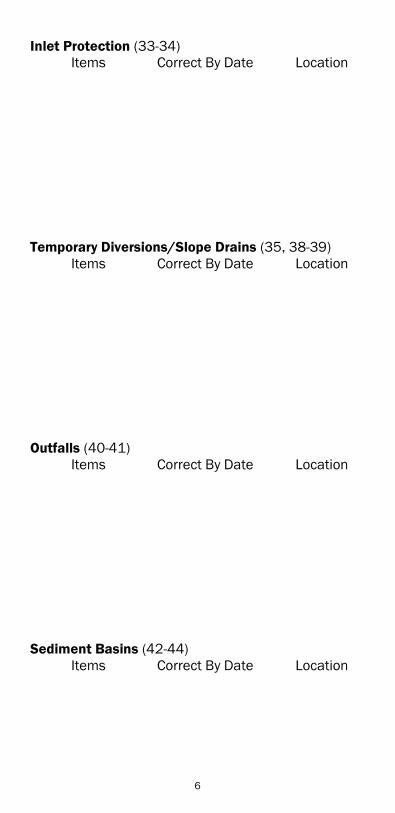
Inlet Protection (33-34) Items Correct By Date Location
Temporary Diversions/Slope Drains (35, 38-39) Items Correct By Date Location
Outfalls (40-41) Items Correct By Date Location
Sediment Basins (42-44) Items Correct By Date Location
6

Areas of Interest (Wetland/Prairie/Tree Preservation) (11-12, 45)
Items Correct By Date Location
Stockpiles (46-47) Items Correct By Date Location
Vehicle Tracking (48-50) Items Correct By Date Location
Concrete Washout Areas (51-54) Items Correct By Date Location
7

Staging/Storage Areas (55-56) Items Correct By Date Location
Borrow/Waste Sites (57) Items Correct By Date Location
Fuel/Chemical Storage (58-59) Items Correct By Date Location
Off-Site Discharge (36, 63) Items Correct By Date Location
8

Document Review
SSWPPP Approval
All SWPPPs must be prepared in accordance with the requirements of the ILR10 Permit and provided to the IEPA at: [email protected]
The SWPPP is BDE Form 2342 and ESC Plans. Provide the IEPA (NOI) form and the BDE Form electronically to the IEPA at least 30 days prior to initiating earthmoving activities. The IEPA will provide a notification of coverage letter back to IDOT staff who submitted the SWPPP and NOI. You will also receive an ILR10 Permit number from IEPA. The ILR10 Permit number is unique to your project. Use the permit number on all correspondence with the IEPA.
AA. Contractor Certification Statement Every Contractor and subcontractor will be required to complete his/her own separate certification form. This certification statement is part of the SWPPP and is the RE/T’s documentation that the Contractor(s) understand the SWPPP/ESC measures and will abide by the plan. The Contractor must attend the required preconstruction meeting for ESC. The Contractor must provide scheduling of ESC BMPs and provide type, timing, and location of the Good Housekeeping BMPs.
B. Amending SWPPPs The SWPPP is a working dynamic document that must reflect current storm water and erosion control conditions based upon the last documented inspections. Having a current plan and documenting amendments to the SWPPP is an ILR10 Permit requirement. Amend the SWPPP when there is a change in maintenance, design, construction or operation that creates or reduces potential for pollutant discharge. Items that must be included when amending SWPPPs are: Dates grading activities begin, temporarily cease, or permanently cease
Type, timing and location of temporary and permanent BMPs
Locations where storm water is discharged from the project and what was observed
Areas of soil disturbance Dates when construction activities temporarily or permanently cease
The number of waste receptacles and method of solid waste disposal
Locations, type and maintenance of concrete truck washouts
9
Vehicle equipment, fueling and maintenance locations Amount of rainfall/snowfall Locations where vehicles and equipment enter/exit the project, what was observed, and BMPs implemented to prevent sediment discharge onto pavements
The maintenance activities performed for each BMP. This includes specifically identifying which maintenance activities correspond to each BMP.
Locations where materials and chemicals are stored, the BMPS implemented for material and chemical storage to minimize contact with storm water, the type of material and chemical stored and the disposal of materials. Remember, every time the Contractor uses materials and chemicals or brings new materials, or chemicals onto the project, amend the SWPPP to identify how materials are stored to minimize contact with storm water.
CC. Public Posting Requirements Be sure to post the Notification of Coverage letter in a prominent location so that any regulatory agent can view the posting (field office window, next to other permits, etc.).
D. Other Plans, Permits, Letters, and Agreements Check the project commitment file, plan notes, and the SWPPP for any special conditions that the project must follow or how these conditions will affect the implementation of the SWPPP/ESC Plan. Be sure to discuss these conditions with the Contractor(s) at the ESC pre-construction meeting. Point out any special mitigation areas or situations required and the specific protection for sensitive areas. It is important to review other permit requirements such as US Army Corps’ Section 404 Permits to ensure the SWPPP will compliment any Section 404 Permit conditions.
E. Existing and Proposed Drainage The NPDES permit conditions are implemented to control and minimize impact from storm water discharges at construction sites. Be sure to review how storm water enters your project, is conveyed through the project, and locations where storm water is discharged. Familiarize yourself with the BMPs that should be implemented at all discharge locations and what the appropriate timing is for implementing BMPs at discharge locations.
10

FF. CConstruction Staging Schedule Review the project documents to ensure each stage of construction will have adequate BMPs in place to prevent any non-storm water discharges. The SWPPP must contain BMPs to be installed prior to starting earthmoving activities.
GG. Erosion and Sediment Control Plan The ILR10 Permit requires a written narrative (SWPPP) and a graphic plan (ESC Plan Sheets) that clearly depicts all storm water conveyances, locations of temporary and permanent BMPs, discharge points, and other aspects of protecting storm water discharges as described in the SWPPP. Review the ESC Plan Sheets to ensure all BMPs listed in the SWPPP are identified. Understand BMP installation sequences such as perimeter controls, protection of resources and other commitments, critical stabilization, structural controls, temporary storm water conveyances, material storage locations and non-storm water controls.
11
Photo Logging Procedure (Recommended)
EEquipment Copies of Previous
Pictures Contract ESC Plans Extra Camera Battery Extra Memory Chip Photo Data Log Sheets Cell phone (See Below) Digital Camera (8
Megapixel)
GPS Unit Ruler (For Scale) Dry-Erase Board And
Marker Stakes With Flagging To
Substitute A Fixed Point Of Reference
Tripod
Safety For safety reasons, someone else should always know where you are on the site if they cannot accompany you on the ESC inspection. Other areas of concerns are: Inclement weather and slippery or icy conditions Flood conditions (fast, cold or deep water) Poisonous plants (poison ivy, poison oak, cow parsnip, etc) Dangerous insects or animals (ticks, bees, livestock, wandering dogs)
Other hazards waste (broken glass, hypodermic needles, human waste)
Naming Conventions Photos (or videos) should be named clearly and consistently and is formatted as follows (i.e. PH_Contract-Station-Left or Right_LkgDirection_Date) :
PH_####-######-L_Lkg###_yyyymmdd
PH_94356-233600L_LkgNW2_20080423 indicates a photo taken on Contract 94356 at Station 2336+00, Left looking NW on April 23, 2008. “2” signifies that this is the second picture taken looking NW. Alternately, a numeric bearing could be used for the direction. VO is the descriptor for video.
Photo Composition Considerations Include landscape features that are unlikely to change. Take progress photos at the same location and bearing as previous photos.
Take close-up photos looking south to minimize shadows. Keep the sun at your back for long view shots. Take photos from a high vantage to have a site overview. Take a beginning photo of a dry-erase board with the location, subject, contract, date and time written to identify the set of inspection photos.
12

GGeotagging Photos Inexpensive GPS hardware and software can record the X, Y and sometimes Z coordinates and insert this information into the digital photo’s EXIF (Exchangeable Image File Format) data. Having latitude and longitude tagged to each photo allows for easy plotting on a map.
Check the time on the digital camera. Most of these GPS hardware/software combinations require that the time on the GPS unit and the time on the camera match closely. Download and back-up photos often. Maintain a copy of each photo in the ESC file.
13

Understanding the Erosion and Sediment Control System for Your Project
The erosion and sediment control (ESC) for the project must be implemented with the understanding that an ESC system is to be constructed. The ESC system is an engineered solution designed to manage storm water to minimize erosion. Erosion could result in sediment being discharged through the project limits creating nuisance conditions or sediment discharged off-site. Critical to the success of an ESC system is understanding the interaction or codependency of the Best Management Practices (BMPs) to control storm water into, through and off the construction site. The correct BMP for the situation, and the timing of the BMP installation for the particular site situation, is paramount to whether the ESC system will work. Evaluate each BMP by its contribution to the entire system and not simply as a BMP meeting the IDOT standard. Think of your ESC project in terms of what would happen if a particular BMP or a set of BMPs were not in place to protect critical areas. Before BMPs are put into place, the following actions should be taken:
1. Evaluate the system of BMPs to locate all the storm water contribuations; water coming into the project, flowing though the project, and discharging off the project. The plan should depict BMPs for each of these areas and the timing of those BMP installations. Consult the contract SWPPP form, ESC Plans, and Contractor’s proposed project schedule to check the timing of BMP installation and if there will be any gaps in protection during the construction sequence so that critical areas are not affected.
2. Identify the critical areas for protection such as discharges, sensitive resources, steepest ditches for concentrated flows, embankments adjacent to discharge points and transitional areas. Transitional areas often occur on construction projects where clearing and earthwork meet culvert and drainage activities, where temporary BMPs meet permanent BMPs, and where construction staging changes.
3. Evaluate where potential problem areas might occur and what the consequences of those problem areas might be: compromise or overwhelm other BMPs, off-site discharge, nuisance conditions on-site, etc.
4. Be familiar with the reasons the system of BMPs was selected for your project.
5. Communicate any concerns with the Contractor to ensure both you and the Contractor understand how the ESC system is to be implemented, or may require modification (extra BMPs) prior to initiating construction.
6. Erosion Control is always more cost effective than Sediment Control.
14
Avoiding Sensitive Areas
DDefinition
Actively avoid areas where an existing high quality environmental feature is present and construction storm water runoff has a potential for damage. The sensitive properties can be Federal, State or privately held lands. Where Practice Applies
Sensitive areas include floodplains, wetlands, riparian areas, specimen trees, natural vegetation, nature preserves, threatened and endangered species habitats, historic preservation sites, and 303(d) listed receiving waters www.epa.state.il.us/water/tmdl/303d-list.html. Many counties and planning authorities utilize mandatory stream setbacks during construction. Check the SWPPP to see if the setbacks apply to the project.
Normal sheet-flow into the sensitive area may be altered and concentrated by construction activities and cause damages beyond the temporary fence.
Advantages Avoid penalties
Disadvantages Reduces area within and adjacent to construction operation for staging, storage or access
Installation Establish a relationship with owners of the sensitive site in order to identify concerns and ensure understanding of construction activities.
Physically separate the work area from the sensitive areas and sign the location before other work begins in the area.
Normal PEBs may require fortification to provide a fail-safe adjacent to sensitive area intrusions.
Consider installing permanent right- of- way fence early in construction and place PEB tied to the right- of- way fence as the fortification method; use in lieu of temporary fence.
Inform the Contractor of the construction activities, and timing of those activities that are allowed in association with sensitive areas.
Ensure that the Contractor understands that construction equipment movement may be restricted. Provide details on the restrictions.
If several construction stages are required, the SWPPP must address all the stages for physical protection, and practices, to avoid storm water discharges to the sensitive area.
15
Exclusive usage of signage is not adequate notice of protection.
IInspection Areas of Concern Inspect fencing for intrusions, tears, sediment discharges through the fence.
Check for signs of vehicular, personnel or other intrusions into area.
Maintenance Restore fences which are not upright. Clean posted ‘No Entry’ signs as needed. Most intrusions will necessitate ION submittal.
Contact authorities in charge of the sensitive site to identify a cleanup plan prior to removing any discharged sediments to the sensitive area. Document this coordination in the project ESC file and depict the cleanup in the SWPPP update.
16

Temporary Erosion Control Seeding
Definition Temporary erosion control seeding is used to establish quick growing plants to stabilize disturbed areas, preventing soil from being carried off-site by storm water runoff or wind, and areas that will not have permanent stabilization installed for a period of time, or where the area may be disturbed at a later date. Stabilization measures must be initiated no more than seven days after construction activity has ceased regardless of when permanent stabilization is anticipated. (See ILR10 Permit for stabilization timeframes)
Where Practice Applies Cleared, barren or sparsely vegetated soil surfaces where vegetative cover is needed for less than one year (e.g., Dams, Temporary Sediment Basins, Temporary Road Banks, Topsoil Stockpiles, Highway Slopes)
Advantages Lower cost than similar BMPs Fast stabilization when conditions are conducive Minimal effort to remove when no longer needed May reduce amount of maintenance for earthen structures (e.g., dikes, diversions, dams)
Weekly application ensures seed is available when conditions favor germination
Seed availability
Disadvantages Weekly seeding will not prevent erosion The seed remains dormant until conditions allow germination
Relying exclusively on temporary seeding is inappropriate.
Installation Seeding shall conform to Section 280 of the Standard Specifications.
All exposed areas are to be seeded using temporary erosion control seeding every seven days.
If soils are hard packed or caked, light disking is necessary prior to seeding.
The rate of application is to be 100 lbs/acre. Either winter wheat or spring oats seeding will be used depending on the time of year.
Apply the seed by hand broadcasting to achieve a uniform coverage.
17
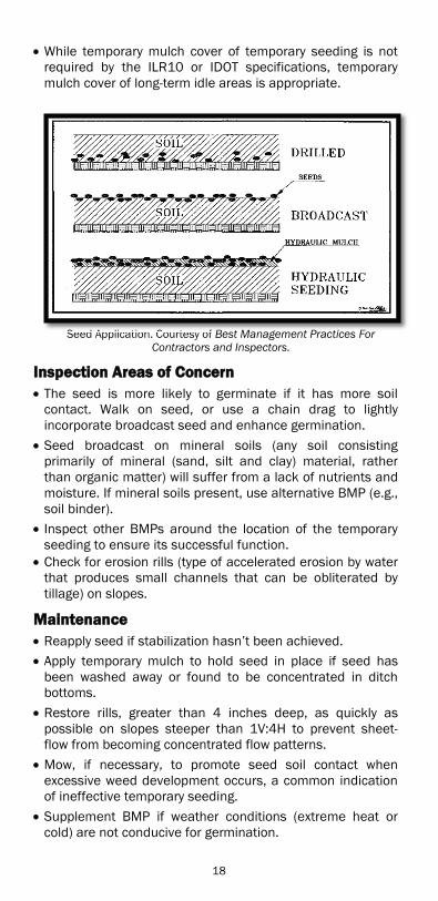
While temporary mulch cover of temporary seeding is not required by the ILR10 or IDOT specifications, temporary mulch cover of long-term idle areas is appropriate.
Seed Application. Courtesy of Best Management Practices For
Contractors and Inspectors.
Inspection Areas of Concern The seed is more likely to germinate if it has more soil contact. Walk on seed, or use a chain drag to lightly incorporate broadcast seed and enhance germination.
Seed broadcast on mineral soils (any soil consisting primarily of mineral (sand, silt and clay) material, rather than organic matter) will suffer from a lack of nutrients and moisture. If mineral soils present, use alternative BMP (e.g., soil binder).
Inspect other BMPs around the location of the temporary seeding to ensure its successful function.
Check for erosion rills (type of accelerated erosion by water that produces small channels that can be obliterated by tillage) on slopes.
Maintenance Reapply seed if stabilization hasn’t been achieved. Apply temporary mulch to hold seed in place if seed has been washed away or found to be concentrated in ditch bottoms.
Restore rills, greater than 4 inches deep, as quickly as possible on slopes steeper than 1V:4H to prevent sheet-flow from becoming concentrated flow patterns.
Mow, if necessary, to promote seed soil contact when excessive weed development occurs, a common indication of ineffective temporary seeding.
Supplement BMP if weather conditions (extreme heat or cold) are not conducive for germination.
Seed Application Courtesy of Best Management Practices For
18

Sod
DDefinition Stabilization of fine graded disturbed areas using a continuous cover of grass sod.
Where Practice Applies Disturbed areas, requiring immediate cover for erosion protection or sediment control
Residential or commercial areas where quick establishment or aesthetics are factors
Locations where surface water concentrates such as waterways carrying intermittent flows
Areas adjacent to drop inlets or in swales All other areas where seeding is not appropriate but an immediate vegetative cover is required
Advantages Provides instant cover of soil for immediate erosion control Provides soil stabilization and acts as a filter for runoff Can be installed during times of the year when seeded grass may fail.
Disadvantages Higher initial cost compared to seed Additional site preparation required More intensive follow up compared to other BMPs
Installation Only use sod harvested, delivered and installed within the same 48-hour period.
Do not place sod in extreme temperatures. Prior to temporary or final sod placement, fine grade the base soil.
The first row of sod shall be laid in a straight-line perpendicular to the slopes with remaining rows placed parallel to and butted tightly against each other.
Lateral joints shall be staggered to promote more uniform growth and strength.
Where sod is installed on slopes greater than 1V:2H, or in areas of concentrated flows, sod shall be staked to prevent movement.
Do not place sod atop gravel or non-soil surfaces. Do not place sod on frozen ground. Irrigate sod according to Article 252.08.
19

IInspection Areas of CConcern Fill or shape any irregularities in the soil’s surface to prevent the formation of depressions or water pockets in the sod.
Prior to sod placement, the soil shall be clear of trash, debris, large roots, branches, stones and clods larger than 1 inch in length or diameter.
All sod shall be free of disease, insects and weeds and consist of a three-fourths inch mat of vigorous turf.
Look for gaps at joints where sod pieces abut. Give special attention to abrupt and short ditch grade changes.
MMaintenance Limit foot traffic to low use for the first two to three weeks. Ensure irrigation rate does not result in runoff. Install salt-tolerant sod where needed. Replace when >25% of any individual piece of sod is no longer viable.
Restore areas where rolling edges are present or sod is displaced.
20

Mulch
Definition Loose applied straw mulch, hydraulic mulch, gravel mulch, compost or organic waste originating in the right-of way can reduce erosion by absorbing raindrop energy, provide stabilization during establishment of grass/vegetation and reduce soil moisture loss due to evaporation. Additionally, mulch moderates soil temperature, prevents seed displacement, protects seed from predation, controls weed growth and eventually improves soil texture.
Wood or paper mulch is biodegradable and exhibits good moisture retention and weed control. The decay of freshly produced chips from recently living woody plants, consumes nitrate; this is often offset with a light application of a high-nitrate fertilizer.
Straw mulch is lightweight, biodegradable and pH neutral, exhibits good moisture retention and weed control but may be contaminated by unwanted seeds.
Compost, a kind of mulch, is organic matter where the decomposition process has already begun. The heat of the decomposition process kills weed seeds and the process itself provides nutrients that are more readily available for plant growth. Compost improves soil structure (the arrangement of soil pores), reduces runoff and evaporation, results in better plant and seed growth by providing nutrients more readily, provides greater soil aeration and weed control. Compost can offset some of the fertilizer requirements and introduce soil microbes into the topsoil. Compost can serve multiple purposes on a single site by replacing traditional BMPs such as silt fence and diversions, resulting in a direct cost savings to the project. Unlike other mulching methods, compost is suitable for steeper slopes and, according to the USEPA, can be applied on frozen ground. Though compost is more expensive than other mulch methods, compost provides additional benefits, including bioremediation, ability to lessen soil compaction, odor absorption and binding of heavy metals.
Where Practice Applies At the base of trees or shrubs Never in drainageways On temporary or final seeded areas away from traffic where it would be blown away. Mulch placement on steep slopes is limited to hydraulic mulch or ECBs and TRMs.
Advantages Provides immediate, but temporary, soil stabilization Can be used to control dust or mud.
21

Disadvantages Improper application of tackifier will result in loose or lost mulch.
Loose mulch should not be used during winter shutdown, substitute stabilized mulch during this period.
Installation Methods (Standard Specifications Article 251.01) o Straw o Stabilized straw o Hydraulically applied mulch o Stabilized compost
Two T/Ac equates to 80 bales with dimensions: 14” x 36” x 18” (Use 50 lbs per bale).
Never apply mulches on frozen soil (excluding compost and aggregate mulch).
If straw is used, it may be stabilized by an overspray of hydraulic mulch, or applied simultaneously with or immediately followed by a chemical mulch binder as described in the Standard Specifications, Article 251.03.
Do not apply mulch in windy conditions.
Inspection Areas of Concern Ensure continued and uniform coverage, no exposed soil Check for erosion rills beneath “tackified” mulch Excessive coverage when used with seed
Common BMP Points of Concern Mulch should normally smell fresh, but sometimes develops a toxicity that causes it to smell like vinegar, ammonia, sulfur or silage. The noxious odor occurs when material with ample nitrogen content is not rotated often enough and forms pockets of increased decomposition. The pockets of decomposition may become anaerobic (without oxygen) and produce phytotoxic (poisonous to plants) materials in small quantities. Once exposed to the air, the process quickly reverts to an aerobic process (with oxygen), though these toxic materials may continue to be present. If mulch is placed around plants before the toxicity has dissipated, then nearby plants could be damaged or killed depending on their hardiness. Plants that are predominantly low to the ground or freshly planted are the most susceptible, and the phytotoxicity may prevent germination of some seeds. Incompletely processed compost may also be phytotoxic.
Maintenance Repair straw if blown or washed away, or if hydraulic mulch washes away.
Place tackifier or an ECB if mulch does not control erosion.
22

Soil & Mulch Binders
DDefinition
Consist of plant material-based (short and long-lived), polymeric emulsion blends (e.g., spray-on water soluble anionic polyacrylamide, PAM), and cementitious-based binders which are applied to exposed soil, designed to provide temporary soil stabilization in low-traffic areas. Soil Binders provide temporary protection from erosion by raindrop impact or wind. Soil Binders are also appropriate when combined with hydraulic mulches or on top of loose mulch to improve its erosion control effectiveness and to provide stabilization. Check SP for requirements.
Plant Material-based (Short-Lived) o Guar: natural hydrocolloid with dispersant agents o Psyllium: fine coating of plantago seeds o Starch: granular cornstarch
Plant Material-based (Long-Lived) o Pitch and Rosin Emulsion
Polymeric Emulsion blends o Acrylic Copolymers and Polymers o Liquid Polymers of Methacrylates and Acrylates o Copolymers of Sodium Acrylates and Acrylamides o Poly-Acrylamide and Copolymer of Acrylamide o Hydro-Colloid Polymers
Cementitious-based binders o Gypsum-based product mixed with water to form
a protective crust on the soil surface
Where Practice Applies Areas where grading activities will soon resume. Areas that require short-term stabilization. Areas with soil made of fine silts, clays or colloids.
Do not use where overspray onto the traveled way, sidewalks, lined drainage channels, and existing vegetation.
Do not apply to frozen soil, areas with standing water, under freezing or rainy conditions, or when the air temperature is below 40°F during the curing period.
Not suitable for areas receiving concentrated flow, slopes exceeding 1V:3H as a stand-alone practice or on compacted embankment.
Not suitable for areas with pedestrian or vehicular traffic.
Advantages Polymeric emulsion blends and cementitious binders have moderate to high resistance to abrasion.
Plant material-based binders have high resistance to leaching.
Plant material-based (short-lived) has good compatibility with existing vegetation.
23
DDisadvantages Cannot insulate soil or retain moisture. May become slippery. May not perform well in conditions with low humidity or low temperatures.
Plant material-based binders have low resistance to abrasion.
Polymeric emulsion blends and cementitious binders have poor compatibility with existing vegetation.
Chemical stabilizers, when improperly applied, can create impervious surfaces which may increase storm water runoff and are usually more expensive than vegetative practices.
Installation Fines and moisture content are key properties of surface materials. Consider a soil binder’s ability to penetrate, likelihood of leaching and ability to form a surface crust on surface materials.
Application frequency can be affected by subgrade conditions, surface type, climate and maintenance schedule. Frequent applications can lead to high costs and added environmental cleanup. Minimize application frequency by ensuring the soil binder has good penetration, low evaporation and good longevity.
Do not apply if surface is very wet, frozen soil, or when ice is present.
Roughen untreated soil surface and verify that sufficient moisture for binder is present to achieve uniform penetration. Preparing the soil in this manner will ensure binder adheres to the soil.
Application should include spray passes in both directions to ensure adequate coverage.
Require a minimum curing time until fully effective, usually 24 hours.
Inspection Areas of Concern Inspect for cloudy water, sediment rills, cloudy discharges at outfalls, and sediment deposits in drainageways.
Inspect integrity of binder after rainfall.
Maintenance Reapply soil binders after heavy rainfall events if spot failures occur.
Check manufacturer’s specification for re-application criteria.
24

Erosion Control Blanket (ECB)
Definition
A preformed protective blanket of straw, other plant residue, or plastic fibers bound into a mat, usually with a plastic mesh on one or both sides. ECBs are designed to protect soil surfaces from raindrop impacts and overland flow during establishment of grass/vegetation and to reduce soil moisture loss due to evaporation.
Where Practice Applies Used for permanent seeding, winter shutdown, temporary stockpiles, or erodible areas where temporary stabilization may be required (e.g., steep slopes, ditches).
Implement ECBs for a maximum slope gradient of 1V:3H and a flow velocity for ditches between 2 - 7 feet per second (fps). Installing ECB to establish turf in flat areas is cost prohibitive.
Plastic meshes are inappropriate adjacent to natural areas (e.g., preserves and state parks); instead use a natural fiber woven mesh. Sensitive environmental locations require natural weave netting, allowing animals to free themselves.
Advantages Provides immediate protection for soil surface Ranges from short-term to permanent (See Turf Reinforcement Mats) use
Less susceptible to displacement by wind, rain and traffic
Disadvantages Higher material cost than mulch Sometimes difficult to identify manufacturer and/or product Difficult to see erosion under the blanket
Installation for Erosion Control Blankets Each ECB shall conform to Article 1081.10 of the Standard Specifications.
Verify that the blanket delivered on-site is the blanket specified in the accompanying manufacturer’s certification.
Blanket will arrive on the jobsite with information about the time frame for blanket decomposition.
Blankets are not recommended for areas with high pedestrian or recreational traffic due to tripping hazards. Areas to avoid include between curb/sidewalk. Use sod or stabilized mulch in those areas.
Prior to installation, the ground shall be prepared according to Article 251.04 of the Standard Specifications (SS). The blanket shall be in firm contact with the soil, and anchored per Article 251.04 of the SS. Rolling a blanket down a slope will not provide the necessary firm contact.
25
Some manufacturers paint stapling patterns on their ECBs. Staple patterns differ between slopes and have distinct colors.
Visual inspection can give an approximate service life for each ECB. Use straw, hay and excelsior primarily for short-term stabilization. The presence of coconut fiber indicates longer-term use.
Most manufacturers color their web according to service life (i.e. common practice is to use white for short-term, green for mid-term and black for long-term use).
On slopes and in low flow channels, the blanket shall be unrolled upstream to downstream and parallel to the direction of flow.
Blankets should be toed in along roadway’s edge to prevent passing traffic from lifting edge.
If more than one blanket length is required, the material shall overlap over the downstream piece and have stapled edges per specifications.
Inspection Areas of Concern Check for erosion under the blanket if dislodged staples, improper spacing and tenting of the blanket is present.
Under blanket erosion is commonly the result of not toeing in at the top of the slope.
Check the low end of the blanket for sediment buildup, this indicates that water is flowing beneath an ECB.
Inspect blanket areas that transition into other drainageways to ensure no gaps in coverage occur where the blanket transitions to another form of protection.
Maintenance Repair damage due to water running beneath the blanket and restore ECBs when displacement occurs. Reseeding may be necessary.
Replace all displaced ECBs and restaple.
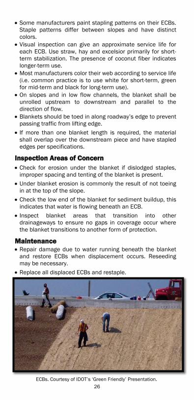
ECBs. Courtesy of IDOT’s ‘Green Friendly’ Presentation.
26
Turf Reinforcement Mats (TRM)
DDefinition
Provide effective and immediate stabilization of slopes and channels, before, during and after the establishment of vegetation. TRMs provide protection from wind and water erosion and reduce soil moisture loss due to evaporation. Use TRMs, a non-degradable rolled erosion control product (RECP), typically for long-term stabilization and serve as an intermediate BMP between hard armoring and ECBs.
Where Practice Applies On steep slopes below pipe or water discharge Areas inaccessible to the implementation of other BMPs Vegetated channels where erosion potential is high Slopes and shorelines adjacent to waterways or environmentally sensitive areas
Slopes and disturbed soils where mulch is anchored Disturbed areas where plants are slow to develop Stockpiles or where hard armoring is inappropriate
Advantages Provide immediate, significant stabilization Are thicker, stiffer and denser than ECBs Can serve either transitional or long-term to provide additional structure to the soil/vegetation matrix
Provide added root reinforcement, compared to ECBs, allows vegetation to withstand higher flow velocities
Good solution for areas requiring long-term stabilization
Disadvantages More expensive than other erosion control measures Not appropriate for excessively rocky sites, access areas or areas where the final vegetation will be mowed
May have a minimum flow rate limitation on bare soil of 7-12.5 fps and a maximum flow rate limitation of 16-22 fps on vegetated sites
TRMs do not operate at peak shear stress levels until fully vegetated
Installation Review manufacturer’s label to ensure TRM meets material specifications for flow conditions, degradation and soil type.
TRMs are toed into the soil, installed and stapled following the manufacturer’s staple pattern.
TxDOT at ftp://ftp.dot.state.tx.us/pub/txdot-info/mnt/erosion/soilerosionblankets.pdf has STDs summarizing TRM installation details from various manufacturers.
27
For TRMs laid out over a prepared seedbed, follow installation guidelines for biodegradable ECBs.
IInspection Areas of Concern A displaced TRM may indicate that ditch flow exceeds the shear capacity of BMP. Before contacting Designer, verify that the TRM was properly toed in.
Check for correctly installed lap joints and adequate stapling.
Look for tire tracks and inform Contractor that no vehicles may drive over TRMs.
Check for erosion cutting around or beneath TRMs. If mowing is required over the TRM areas, set the mowing height to avoid the TRM. Inspect the locations to ensure the mowing operator has not caused damage.
Check for toed in trenches.
Maintenance Repair improper toe entrenching of TRM. Correct undermining, gaps, displacement, or storm water flowing around or under the TRM.
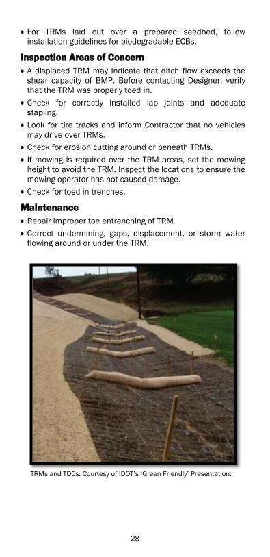
TRMs and TDCs. Courtesy of IDOT’s ‘Green Friendly’ Presentation.
28
Perimeter Erosion Barrier (PEB)
DDefinition
PEBs intercept sheet-flow and settle out sediment upslope while allowing runoff to filter through very slowly, and redirect water from slopes or areas of exposed soil.
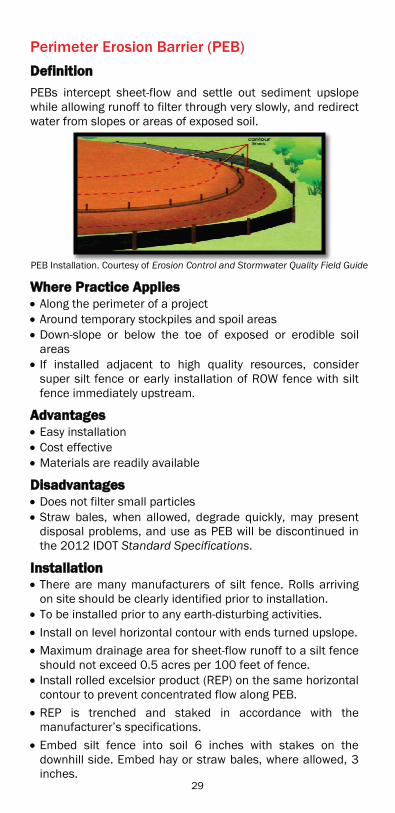
PEB Installation. Courtesy of Erosion Control and Stormwater Quality Field Guide
Where Practice Applies Along the perimeter of a project Around temporary stockpiles and spoil areas Down-slope or below the toe of exposed or erodible soil areas
If installed adjacent to high quality resources, consider super silt fence or early installation of ROW fence with silt fence immediately upstream.
Advantages Easy installation Cost effective Materials are readily available
Disadvantages Does not filter small particles Straw bales, when allowed, degrade quickly, may present disposal problems, and use as PEB will be discontinued in the 2012 IDOT Standard Specifications.
Installation There are many manufacturers of silt fence. Rolls arriving on site should be clearly identified prior to installation.
To be installed prior to any earth-disturbing activities. Install on level horizontal contour with ends turned upslope. Maximum drainage area for sheet-flow runoff to a silt fence should not exceed 0.5 acres per 100 feet of fence.
Install rolled excelsior product (REP) on the same horizontal contour to prevent concentrated flow along PEB.
REP is trenched and staked in accordance with the manufacturer’s specifications. Embed silt fence into soil 6 inches with stakes on the downhill side. Embed hay or straw bales, where allowed, 3 inches.
ll ti C t f E i C t l d St t Q lit Fi l
29

Compact trench fill material to prevent seepage. When required for silt fence, splice the fabric at a support post with a minimum 6 inches overlap, fold over and securely fasten.
Never install silt fences in or across concentrated flow paths. Replace PEB intercepting concentrated flows with a BMP intended for concentrated flows.
When j-hooks are used to support silt fence; do not allow splices of fabric between the silt fence PEB and the anchoring points or the j-hook segment.
Silt Fence. Courtesy of IDOT
Inspection Areas of Concern Do not use PEBs in areas of concentrated flows (e.g., streams, channels, drain inlets).
Maintain PEB silt fence used as “No Intrusion” practice in accordance with inspection tips.
If erosion is present under this PEB, look for correct trenching depth, backfilling and compaction.
Pay special attention to transitional areas such as at culverts where PEB gaps could allow sediment to discharge.
Maintenance Repair tears, gaps or undermining. Restore leaning PEB and ensure taut.
Repair or replace any missing or broken stakes immediately.
Clean PEB if sediment reaches one-third height of barrier. Remove PEB once final stabilization establishes since PEB is no longer necessary and should be removed.
Repair PEB if undermining occurs anywhere along its entire length.
Additional Considerations If PEB silt fence is pushed over, leaning, etc. due to a storm event(s), then Illinois State Toll Highway Authority’s (ISTHA) super silt fence or Minnesota’s Tie Back system may be an appropriate alternative to silt fence. Contact the ESC Coordinator for assistance.
Silt F C t f IDOT
30

Perimeter Vegetated Buffer (VB)
DDefinition
An area of established vegetation intended to absorb energy from sheet-flow storm water discharge. PVB is used as an alternative to PEB where there is sufficient space.
Where Practice Applies Where vegetation can be temporarily preserved or established and utilized for sediment control
In areas where surface runoff is discharged as sheet-flow VBs are used to filter sediment from sheet-flow Are most effective on sites where other BMPs have been implemented in the erosion source area
Advantages Minimal maintenance required High aesthetic appeal Preserving existing buffers is extremely cost effective
Disadvantages Maximum drainage area is 5 acres Not as effective when used on non-uniform slopes Not appropriate for use during late-winter/early-spring when soil is saturated and vegetation cover is flattened, though can be supplemented with geosynthetics through this period to maintain effectiveness
Does not achieve high pollutant removal If improperly designed or maintained, may allow mosquitoes to breed
Installation Establish buffers prior to directing runoff from new impervious areas onto the buffer.
VB slopes shall be 1V:6H or flatter. Native riparian vegetation is preferred in the buffer strip adjacent to streams. Alternative vegetation consistent with these purposes is suitable next to agricultural fields.
The length (perpendicular to sheet-flow) is equivalent to half the drainage area divided by the buffer strip width, in feet. The minimum buffer strip width is 25 feet.
Near larger streams, or in natural settings, a wider buffer may be specified.
Designate buffers as no entry areas by use of signage and/or temporary fence.
Avoid concentrated flows through the VB. If inescapable, use other measures upstream of the buffer to spread the flow.
31

IInspection Areas of Concern Evaluate intrusion of sediment onto or across VB to determine effectiveness under current conditions during design rainfall event (See SWPPP for guidelines).
Inspect buffer areas for signs of pollutant discharge, weed infestation, chemical degradation, sediment buildup or non- storm water discharges passing through the buffer.
MMaintenance Remove sediments collected in the buffer zone. Replace existing plantings destroyed by the sediment intrusion.
Install PEB(s) and Temporary Pipe Slope Drain(s) to prevent the repetition of sediments collecting in the buffer, or entering the receiving water.
Remove undesirable vegetation (noxious weeds, volunteer vegetation) present in VB with proper techniques.
Remove sediment from VB when sediment has covered one-third the length of the buffer.
Remove soil from VB and temporarily stabilize with seed, mulch or another temporary stabilization method.
If clean sediment discharges from VB, implement other BMP(s) to stabilize buffer until restored.
Vegetated Buffer. Courtesy of Illinois Urban Manual
32

Temporary Ditch Checks (TDC)
Definition
A device placed perpendicular to flow in swales or shallow drainage ditches to reduce velocity of flowing water, thereby reducing scour and channel erosion, encouraging deposition of sediment and filtration in the created small ponding areas, and promoting infiltration where suitable soils are present.
Where Practice Applies Any ditch or drainageway that may experience siltation, erosion or scour, or any stable ditch that receives upland sediment laden water
Advantages Decreases velocity, erosive forces and water’s sediment carrying capacity
Relatively inexpensive to install Usually minimum equipment required
Disadvantages Not for permanent use Not appropriate for use on steep ditches susceptible to slumping or creeping
Most not appropriate for flow velocities higher than 8 fps (See Aggregate Ditch Checks)
Rolled excelsior and urethane foam are heavy when wet Relatively high maintenance required
Installation Space according to Figure 41-3B. in Chapter 41 of the BDE Manual. The top of the downstream check shall be at the same elevation as the bottom of the upstream check.
Must be long enough to ensure center of structure is at least 6 inches lower than outside edges of check to allow water to flow over middle of ditch check and not around edges. Checks installed in very high flow locations will require more than 6 inches to prevent flow around ends.
Aggregate See section on Aggregate Ditch Checks.
Urethane Foam/Geotextile The apron is pinned into the soil. Pinning should begin in the middle and worked out toward the edges.
Refer to approved product list.
REPs Place stakes through mesh on the down slope side on an approximately 45° angle toward the up slope side.
33
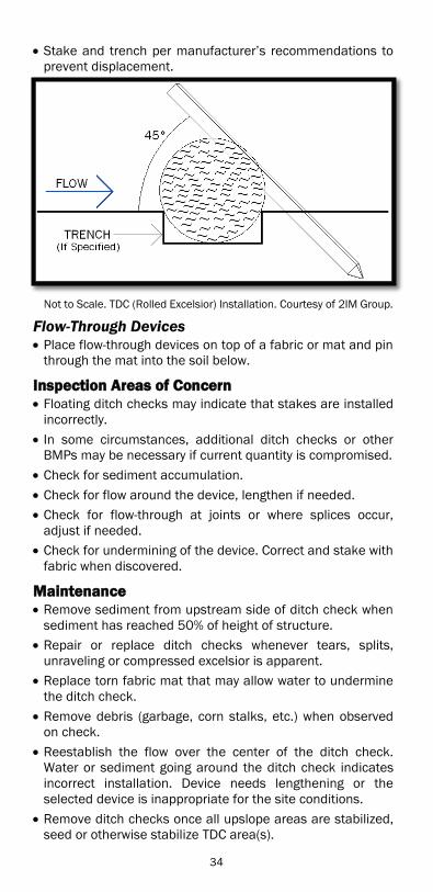
Stake and trench per manufacturer’s recommendations to prevent displacement.
Not to Scale. TDC (Rolled Excelsior) Installation. Courtesy of 2IM Group.
Flow-Through Devices Place flow-through devices on top of a fabric or mat and pin through the mat into the soil below.
Inspection Areas of Concern Floating ditch checks may indicate that stakes are installed incorrectly.
In some circumstances, additional ditch checks or other BMPs may be necessary if current quantity is compromised.
Check for sediment accumulation. Check for flow around the device, lengthen if needed. Check for flow-through at joints or where splices occur, adjust if needed.
Check for undermining of the device. Correct and stake with fabric when discovered.
Maintenance Remove sediment from upstream side of ditch check when sediment has reached 50% of height of structure.
Repair or replace ditch checks whenever tears, splits, unraveling or compressed excelsior is apparent.
Replace torn fabric mat that may allow water to undermine the ditch check.
Remove debris (garbage, corn stalks, etc.) when observed on check.
Reestablish the flow over the center of the ditch check. Water or sediment going around the ditch check indicates incorrect installation. Device needs lengthening or the selected device is inappropriate for the site conditions.
Remove ditch checks once all upslope areas are stabilized, seed or otherwise stabilize TDC area(s).
34

Aggregate Ditch Checks (ADC)
DDefinition
An ADC acts as a temporary containment structure to slow ditch flow as a means to capture sediment in the drainage channel during the construction phase or as a structural BMP. When properly installed an ADC will reduce, control and even prevent erosion within the swale/ditch. Only use ADCs in combination with other stabilization and/or SCPs.
Where Practice Applies In grass swales, open channels or ditches that drain 10 acres or less
Ditches where velocities exceed 8 fps
Advantages Slows flow velocity and promotes infiltration Captures sediment
Disadvantages Not recommended for slopes greater than 20%, except when supplemented with TRMs
Not appropriate for flow velocities less than 4.9 fps Frequent maintenance required Not intended for fine sediment trapping
Installation Width of the ADC is the length required to reach from foreslope to back slope. Must be long enough to ensure center of ADC is lower than outside edges to allow water to flow over middle and not around edges.
SECTION B-B, STD 280001. All dimensions are in inches.
35

Construct perpendicular to the flow path in drainage ditches/swales.
Filter fabric (geotextile) shall be placed below and between the riprap (RR) and coarse aggregate (CA).
Install according to Standard Drawing (STD) 280001. Construct so that the low point is in the center. If the low point is present elsewhere, regrade.
IInspection Areas of Concern Check for the high waterline to note where water discharges across the BMP.
In circumstances where current quantity of ditch checks is compromised, additional ditch checks or other BMPs may be necessary.
Check for sediment accumulation. Check for flow around the device and lengthen if needed. Check for undermining of the device. Correct and stake with fabric when discovered.
Maintenance Remove sediment from upstream side of ADC when sediment has reached 50% of height of ADC.
Replace the CA and fabric when sediment has filled all voids in the stone, so that sediment is filtered and discharged.
Repair or replace fabric whenever tears, splits or unraveling are apparent.
A second failure will generate a designer review. Restore outside slopes to 1V:2H. Stone placed for restoration is the same size as originally specified to allow proper interlock.
Restore center of the ADC periodically to ensure it is lower than the sides.
Retrench the fabric if undercutting occurs. Reduce center flow line or lengthen ADC if water flows around device.
36

Storm Drain Inlet Protection
Definition Prevents sediment from entering storm drain systems. Inlet protection is achieved by use of filters or by impounding areas around or upstream of an inlet to allow sediment to settle. Storm Drain Inlet Protection is a secondary BMP and is used in conjunction with erosion control BMPs.
Where Practice Applies Protects every storm drain inlet receiving or having potential of receiving sediment-laden runoff from a construction site.
If areas draining into inlets are greater than 1 acre, a sediment basin or sediment trap may be required. The Engineer should contact the designer to determine the appropriate design.
Installing a barrier around an area drain or catch basin located on a grade will cause downstream flooding due to diversion of runoff. Instead, barriers around area drains should only occur when they are located within a sump.
Advantages Simple installation Relatively inexpensive
Disadvantages Inlet protection devices require frequent inspection and cleaning to prevent sediment from overflowing into device
Captured sediment may reduce the flow rate of the inlet protection device resulting in flooding or icing condition
Installation Installed prior to any earth-disturbing activities
Inlet Filters Installed directly on the drainage structure or undergrate of drainage structure resting on lip of frame. Fabric bag shall hang down into structure.
Silt Filter Fence Embed silt filter fence into the earth 6 inches. Use cross bracing to support inlet protection. Do not allow tears in the fabric; fabric must remain taut. Slopes immediately surrounding the silt filter fence shall not exceed 1%. The inlet must remain accessible for removal of accumulated sediment.
Hay or Straw Bales Embed bales into earth 6 inches.
37

Place bales on sides so twine/wire does not make contact with soil.
Shall have no gaps where bales join so that no storm water flows between bales.
Use a minimum of two stakes to stabilize each bale. Slopes immediately surrounding the bales shall not exceed 1%. The inlet must remain accessible for removal of accumulated sediment.
Straw Bale Inlet Protection. Courtesy of ColoradoDOT
IInspection Areas of Concern o Inlet Filters
Check for water standing in filter more than one hour following a rain event
Check for sediment or trash in the filter Check for tears or damage to the filter
o External Application Check for standing water more than one hour following a rain event
Check for tears present in fabric Check for sediment entering device at junction of fabric or bales
Check for undermining
Maintenance Remove sediment from inlet filter basket when basket is 25% full or 50% of the fabric pores are covered with silt.
Remove ponded water on road surfaces immediately. Clean filter if standing water is present longer than one hour after a rain event.
Clean sediment or replace silt fence and straw bale inlet protection when sediment accumulates to one-third the height of the fabric.
Remove trash accumulated around or on top of practice. When filter is removed for cleaning, replace filter if any tear is present.
38

Diversion Dike
Definition
Temporary stabilized ridge, excavated stabilized channel, or a combination of the two, constructed across sloping land to protect work areas from upslope runoff and to divert sediment-laden water to a sediment-trapping facility or stabilized outlet.
Where Practice Applies Above disturbed slopes and above cut or filled slopes to divert sheet-flow to stabilized discharge locations
Below slopes to divert excess runoff to stabilized outlets and treatment facilities
To convey sediment-laden water through a jobsite
Advantages Moves “clear” water around the project Moves off-site “dirty” water through the project Can reduce the volume of runoff passing through disturbed areas
Disadvantages May require a temporary culvert to separate construction traffic from off-site flows conveyed through the project
Installation Grade of the diversion should not exceed 1%. Stabilize temporary diversions with turf, mulch, ECBs, aggregate, or a combination prior to initiating use.
Inspection Areas of Concern Diverted runoff should only discharge onto stabilized areas or a sediment trapping facility.
Check for rills along diversion or erosion at discharge points.
Check for breaches along temporary ridge(s). Check for areas of ponded water other then at discharge points.
Debris along or adjacent to the ridge may indicate overtopping.
Maintenance Fill and regrade rills exceeding a 3 inch depth. Consider additional stabilization (Geotechnical Fabric, Mulch, TRMs, etc.) of flow line if rills re-form.
Regrade slopes where ponding occurs, leading to a softened downslope berm and failure.
After stabilizing the area to mirror surrounding topography, remove the temporary diversion.
Add material or conduit ridge where debris accumulation indicates overtopping.
39
Sediment Removal Dewatering Operations
DDefinition
Removal of suspended sediments from a dewatering operation, including treatment of groundwater removed from an excavation or other area prior to the appropriate discharge of encountered water to prevent the state of offensive conditions in Waters of the State of Illinois. Waters of the State shall be free from sludge or bottom deposits, floating debris, visible oil, odor, plant or algal growth, color or turbidity of other than natural origin.
Where Practice Applies Construction sites, including off-site excavated areas, where the presence of water creates unsafe conditions, potential damage or restricts construction operations
Construction sites where water is present in any form, including intermittent runoff, streams, standing water, ground water or other bodies of water
Where pumping operations occur Intercepted water table Instream work Removal of collected runoff
Advantages Minimizing pollution to Waters of the State Minimizes impact to aquatic life
Disadvantages May be costs associated with disposal of collected, possibly contaminated, sediments
Installation Direct all turbid water removed from construction operations into a temporary or permanent cleaning system (e.g., sediment basin, flocculant polymer treatment system, portable sediment tank, filter strip, stabilized channel).
In 2013, with the reissued ILR10 Permit sediment removal dewatering operations will be mandatory for projects that exceed 10 disturbed acres. The ELG limit will be 280 NTUs (See page 65 for information on NTUs). ELGs will not apply to smaller projects, however, in these cases, the Contractor, shall at all times observe and comply with all Federal and State laws, local laws, ordinances and regulations which in any manner affect the conduct of the work, and all such orders or enactments as exist at the present and which may be enacted later, of legislative bodies or tribunals having legal jurisdiction or which may have affect over the work, an no plea of misunderstanding or ignorance thereof will be considered.
40
In confined areas, floating pumps with flocculant can act as a temporary sediment pond treatment system.
Inspection Areas of Concern Stabilize discharge locations. Inspect discharged water for any clarity and/or sediment leaving the retention areas. The discharged water shall be no more turbid than the receiving water (See page 65 for information on turbidity).
Do not allow any introduction of discharged material into flowing water.
Excavated sediments stored too close to Waters of the State or sediment control facilities.
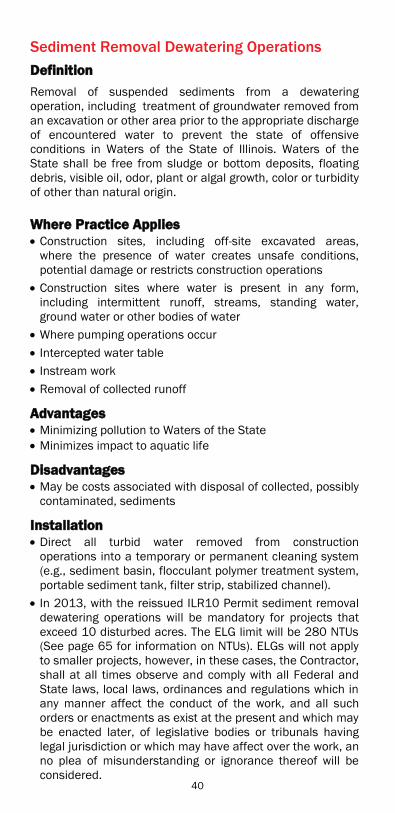
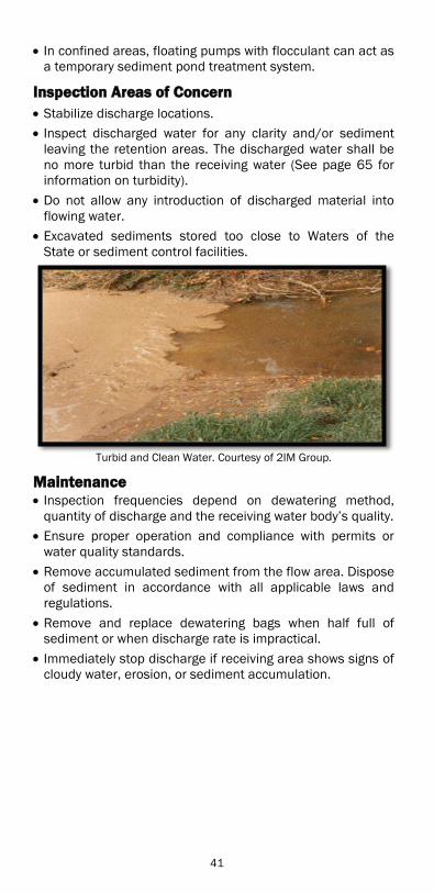
Turbid and Clean Water. Courtesy of 2IM Group.
Maintenance Inspection frequencies depend on dewatering method, quantity of discharge and the receiving water body’s quality.
Ensure proper operation and compliance with permits or water quality standards.
Remove accumulated sediment from the flow area. Dispose of sediment in accordance with all applicable laws and regulations.
Remove and replace dewatering bags when half full of sediment or when discharge rate is impractical.
Immediately stop discharge if receiving area shows signs of cloudy water, erosion, or sediment accumulation.
T bid d Cl W t C t f 2IM G
41

Temporary Pipe Slope Drain
Definition A conduit that conveys concentrated runoff down the face of a cut or fill slope without causing erosion on or at the base of the slope. A temporary pipe slope drain is used in conjunction with a diversion dike.
Where Practice Applies Where concentrated flow of surface water, created by collecting sheet-flow with the diversion dike, must be conveyed down a slope without erosion. On slopes, sheet-flow quickly concentrates into rill erosion then gully erosion, the net result can generate up to 100 times more sediment. Sediment generates geometrically with the length of the flow path.
Where surface water is collected and conveyed down a slope to reduce sheet-flow.
Used until permanent runoff conveyances can be installed and/or permanent vegetation is established.
When runoff is intercepted upstream of a cut or fill section that has not achieved permanent stabilization.
Used as an emergency spillway for a sediment basin.
Advantages Effectively conveys water down slopes when installed Reduces volume of water flowing over a slope at random locations
Disadvantages The maximum allowable drainage area is 1.5 acres per 18-in slope drain
Severe erosion may result if pipe slope drain is not properly maintained
Installation The use of many, smaller pipes is preferable to one large pipe as many, small pipes reduce the damage attendant to a berm failure at the top of the slope.
The Contractor should avoid the placement of any material over the pipe or its inlet and prevent construction traffic from crossing over the pipe.
Construct slope drains from corrugated metal pipe, heavy duty non-perforated corrugated plastic pipe, or a specifically designed flexible tubing.
Anchor the pipe a minimum of every 10 feet with extra anchoring at the outlet.
To prevent stress and failure, install the drain perpendicular to slope contours.
42

Temporary Pipe Slope Drain. Courtesy of 2IM Group.
All temporary slope drains will discharge into the back of sediment traps, into sediment basins or ditches discharging into traps or basins.
The drain should extend beyond the toe of slope and terminate in a 4 foot level section where practical.
Install outlet protection below the pipe outlet for stabilization at discharge points.
Use silt fence or an earthen dike to channel the flow of water to the temporary pipe slope drain. Special attention is required; failure to contain runoff will result in excessive sediments generated.
Inspection Areas of Concern Check that the entrance section to the drain is well entrenched and stable so that surface water can enter freely.
Check berm for areas of undermining or over topping. Check for continuity of pipe. Check for crushed pipe sections. Check anchor for stability.
Maintenance Fill eroded area at inlet with well-compacted soil immediately.
Stabilize outfall to eliminate further scour. Repair leaks along length of pipe and re-compact soil to stabilize pipe.
Reconnect pipe at joints when separation occurs. Restore or increase anchors along length of pipe to ensure pipe stability.
If slope drain washes out it may be necessary to use aggregate-lined channels or additional drains.
T Pi Sl D i C f 2IM G
43
Outlet Protection
DDefinition A section of rock protection, geotextiles, articulated block revetment mat, gabions, RR or other approved manufactured products placed at the outlet end of culverts, conduits, sediment basins to dissipate energy of concentrated flow.
Where Practice Applies Outlets of pipes, drains, culverts, slope drains, diversions, swales, conduits or channels
Outlets located at the bottom of a mild to steep slopes Discharge outlets that carry continuous flows of water Outlets subject to short, intense flows of water, such as flash floods
Points where lined conveyances discharge to unlined conveyances
Advantages Immediate stabilization of area Reduction of depth, velocity and energy of water
Disadvantages Difficulty and expense of cleaning soil from BMP Heavy maintenance required when RR used (e.g., weeds, debris)
Installation Evaluate appropriateness of RR size, thickness, and bedding material if failure or exposed subgrade present. Install additional RR to correct.
The elevation of the downstream end of the apron shall be equal to the elevation of the receiving channel or adjacent ground.
Locate so that there are no bends in the horizontal alignment.
The stone shall be hard and angular where the quality will not disintegrate on exposure to water or weathering.
Place the filter fabric between the stone and underlying soil to provide protection.
Inspection Areas of Concern Inspect BMPs prior to forecast rain, daily during extended rain events, after rain events, weekly during the rainy season, and at two-week intervals during the non-rainy season.
Inspect BMPs subjected to non-storm water discharges daily while non-storm water discharges occur.
44
Inspect apron for displacement of the RR and damage to the underlying fabric. Repair fabric and replace RR that washed away. If RR continues to wash away, consider using larger material.
Inspect for scour beneath the RR and around the outlet. Repair damage to slopes or underlying fabric immediately.
Inspect for accumulated sediment buildup and discharge into outlets, and into and out of outlet protection.
MMaintenance Restore dislodged protection at outlet structures and correct erosion that may occur.
Remove sediment buildup that deposits in the protection. Remedy deficient areas, prone to increased erosion, immediately to prevent greater deficiencies.
Remove sediment when voids are full and replace protection. Protection is reusable if the accumulated sediment is removed.
Temporary devices (temporary pipe slope drains) should be completely removed as soon as the surrounding drainage area has been stabilized or at the completion of construction.
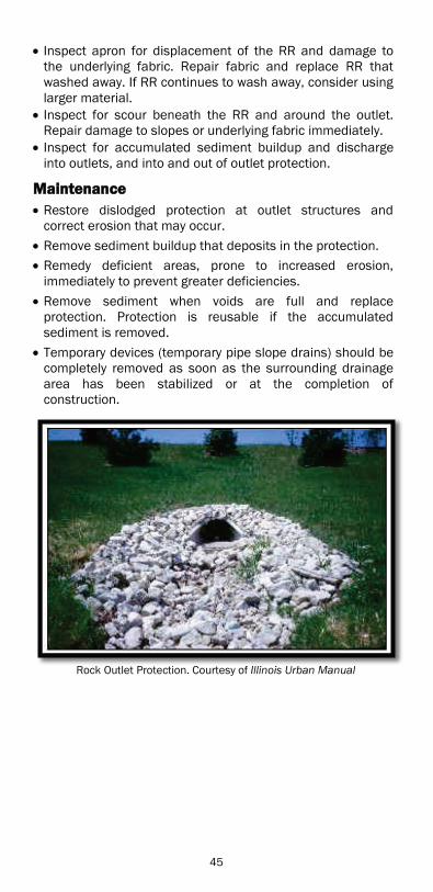
Rock Outlet Protection. Courtesy of Illinois Urban Manual R k O tl t P t ti C t f Illi i U b M l
45

Temporary Sediment Basin
Definition
A controlled storm water release structure formed by excavation or by construction of earthen embankment across a waterway or low drainage area. Temporary sediment basins collect and temporarily detain storm water runoff to provide settling time before runoff discharges from site.
Where Practice Applies For removal of medium to small sized sediment particles (sand and silts)
Contributing areas greater than 5 acres
Advantages Protects downstream area from clogging or damage due to sediment deposits from construction activity
Less costly than mechanical filtration systems Removes high quantity of sediment at one location
Disadvantages Beyond four days, standing water may allow mosquitoes to breed
Clay particles take a long time to settle out Requires a large footprint, which is often difficult to find on a linear construction project
Runoff exiting the temporary sediment basin may require a second treatment if sediment is being discharged at the outfall
A basin placed in the clear zone is a safety hazard which requires shielding with a roadside barrier
Installation Install prior to earth-disturbing construction activities. Maximum depth of temporary sediment basin is 9 feet. Construct an armored outfall. At a minimum, should provide a length-to-width ratio of 2:1 to improve settling.
Stabilize slopes adjacent to temporary sediment basin prior to use.
Access to temporary sediment basin shall be available for maintenance purposes.
A high length-to-width ratio will lead to excessive excavation.
The ADC outlet must be 6 inches lower in the center than at the side slopes.
The bottom must be level and match the outlet types. 46
Maintain the outlet structure to prevent clogging. Woven monofilaments are preferred over fabrics and will produce better results.
Inspection Areas of Concern Inspect outlet for any sediment discharge and discolored water.
Estimate volume of sediment in basin. Check side slopes for sloughing or other slope stability issues.
Check side slopes for erosion, additional stabilization may be required.
Check for water standing in BMP or a wet base greater than four days.
Inspect for mosquitoes.
Maintenance Remove accumulated silt when the basin becomes 50% filled.
Maintain the outlet structure to prevent clogging. Woven monofilaments are preferred over fabrics, and produce better results. Skimmers remove the clearest runoff first.
Correct erosion at outlet and provide stabilization if necessary.
Repair areas that allow seepage from the basin. Implement other BMPs, such as an Advanced Treatment System (anionic polymers); if sediment discharges or other pollutants are identified at the discharge point to appropriately address pollutants.
Replace/augment armoring at the outfall as needed to reestablish outfall integrity.
The presence of stagnant water can result in mosquito larvae, requiring treatment. Mosquito larvae will trigger pumping through an Advanced Treatment System (anionic polymers) or treatment with larvicide. Contact District Environmental staff for guidance.
Regrade base if ponding observed.
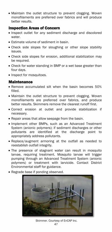
Skimmer. Courtesy of EnCAP Inc.
47

Temporary Sediment Trap
Definition
A containment area where sediment-laden runoff is temporarily detained under stagnant conditions, allowing sediment to settle out before the runoff is discharged. Formed by excavation or by construction of an earthen embankment across a waterway or low drainage area.
Where Practice Applies At the outlets of diversions, slope drains, channels, or in ditches, where low embankment can be constructed
Below contributing areas that are 5 acres or less Locate where sediment-laden runoff enters storm drain or watercourse. Do not locate in live streams.
Advantages Can be placed in narrow rights-of-way in roadside ditches Trap can be constructed/removed as construction progresses
Disadvantages Excessive runoff can compromise the trap resulting in sediment discharge off-site
Installation Construct prior to construction activities draining to trap. Construct an armored overflow. Stabilize slopes around the trap. Max. embankment height is 5 feet, max. excavation depth is 6 feet. Protection required if within clear zone.
Access to sediment detention trap needs to be available for maintenance.
Inspection Areas of Concern Inspect side slope for softened/sloughed side slopes Inspect outlet to ensure water discharges only at design locations.
Inspect outlet for erosion and any needed stabilization. Inspect outlet for any sediment discharge and discolored water.
Estimate depth of material in traps.
Maintenance Clean trap of silt when trap becomes 50% full. Implement other BMPs, such as sand filters, to filter pollutants if sediment discharges or other pollutants are identified at the discharge point.
Regrade to drain. 48

Protect Existing Vegetation & Natural Features
DDefinition
Practices to protect vegetation include tree trunk protection, staged or staggered development, vegetative buffer strips, and signage.
Where Practice Applies Areas of trees, grasses, shrubs, forbs and other woody vegetation designated to remain undisturbed during any stage of construction.
Advantages Cost savings Natural barriers slow water velocity, allow suspended particles to settle out of suspension, absorb energy and allow storm water adsorption, thereby reducing runoff.
Disadvantages May reduce areas available for contractor to stage and store materials and equipment within ROW
Installation Clearly delineate protected areas prior to clearing/grubbing or other soil disturbing activities.
Instruct all on site workers to honor protective devices.
Inspection Areas of Concern Check for stockpiles, vehicular parking and excessive foot or vehicular traffic within the area of protected vegetation.
Inspect locations for any sediment discharges into the protected areas.
Maintenance Replace damaged vegetation with similar species. Check with designer for appropriate replacements.
Restore areas disturbed, disrupted or damaged by the Contractors to pre-construction conditions or better at no additional expense to the contract.
Trim any cuts, skins, scrapes or bruises to the bark of the vegetation and utilize local nursery accepted procedures to seal damaged bark.
Prune all tree branches broken, severed or damaged during construction. Cut all limbs and branches, one-half inch or greater in diameter, at the base of the damage, flush with the adjacent limb or tree trunk.
Smoothly cut, perpendicular to the root, all cut, broken, or severed, during construction, roots 1 inch or greater in diameter.
Cover roots exposed during excavation with moist earth and/or backfill immediately to prevent roots from drying.
49
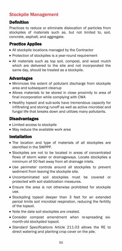
Stockpile Management
DDefinition Practices to reduce or eliminate dislocation of particles from stockpiles of materials such as, but not limited to, soil, concrete, asphalt, and aggregate.
Practice Applies All stockpile locations managed by the Contractor Protection of stockpiles is a year-round requirement All materials such as top soil, compost, and wood mulch which are delivered to the site and not incorporated the same day, should be treated as a stockpile.
Advantages Minimizes the extent of pollutant discharge from stockpile area and subsequent cleanup
Allows materials to be stored in close proximity to area of final incorporation while complying with CWA
Healthy topsoil and sub-soils have tremendous capacity for infiltrating and storing runoff as well as active microbial and fungal life that breaks down and utilizes many pollutants.
Disadvantages Limited access to stockpile May reduce the available work area
Installation The location and type of materials of all stockpiles are identified in the SWPPP.
Stockpiles are not to be located in areas of concentrated flows of storm water or drainageways. Locate stockpiles a minimum of 50 feet away from all drainage inlets.
Use perimeter controls around all stockpiles to prevent sediment from leaving the stockpile site.
Uncontaminated soil stockpiles must be covered or protected with soil stabilization measures.
Ensure the area is not otherwise prohibited for stockpile use.
Stockpiling topsoil deeper than 3 feet for an extended period limits soil microbial respiration, reducing the fertility of the topsoil.
Note the date soil stockpiles are created. Consider compost amendment when re-spreading six-month-old stockpiled topsoil.
Standard Specifications Article 211.03 allows the RE to direct watering and planting crop cover on the pile.
50
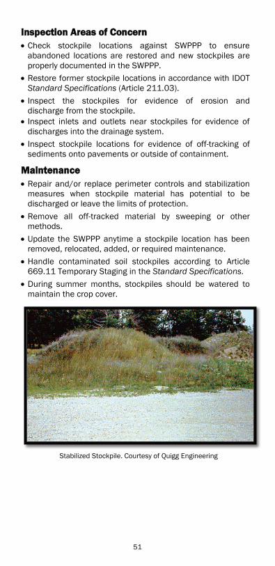
IInspection Areas of Concern Check stockpile locations against SWPPP to ensure abandoned locations are restored and new stockpiles are properly documented in the SWPPP.
Restore former stockpile locations in accordance with IDOT Standard Specifications (Article 211.03).
Inspect the stockpiles for evidence of erosion and discharge from the stockpile.
Inspect inlets and outlets near stockpiles for evidence of discharges into the drainage system.
Inspect stockpile locations for evidence of off-tracking of sediments onto pavements or outside of containment.
MMaintenance Repair and/or replace perimeter controls and stabilization measures when stockpile material has potential to be discharged or leave the limits of protection.
Remove all off-tracked material by sweeping or other methods.
Update the SWPPP anytime a stockpile location has been removed, relocated, added, or required maintenance.
Handle contaminated soil stockpiles according to Article 669.11 Temporary Staging in the Standard Specifications.
During summer months, stockpiles should be watered to maintain the crop cover.
Stabilized Stockpile. Courtesy of Quigg Engineering
51

Stabilized Construction Exits
Definition A BMP that vibrates and removes accumulated mud and dirt off vehicle tires before equipment enters public roads.
Where Practice Applies At all points of construction ingress/egress where sediment can be tracked onto public roads
Advantages Reducing tracking of mud, sediments/other pollutants onto paved roads can prevent deposition of sediments into local storm drains and reduce production of airborne dust
Disadvantages Expensive to construct and maintain If not properly maintained, can become a continued erosion problem
Requires discipline by Contractor to properly access sites
Installation Designed by the Contractor and generally installed at their expense.
Located where the Contractor determines according to their specifications, Illinois Urban Manual (IUM), Practice 930.
Stabilized exits should be designed for heaviest anticipated loads.
Installed prior to major land-disturbing activities. Constructed where construction traffic will be crossing or entering public roadway, alley, parking lot, or sidewalk from unstabilized area.
Locate on level ground where possible. Properly grade each construction exit away from roadway to prevent runoff from leaving construction site.
Inspection Areas of Concern Inspect surrounding area to ensure all construction traffic is using designated construction exit locations and not leaving site from non-stabilized locations.
Inspect all curbs, gutters, inlets, and inlet protection near stabilized construction exits for discharged sediments.
Inspect drainage pipe for damage. Check accumulation of debris in stone.
52

MMaintenance Replenish stone or replace exit if vehicles continue to track sediment onto the roadway from the construction site.
Sweep sediment on roadway from construction activities immediately.
Ensure culverts are free from damage. Use street sweeping in conjunction with this BMP to remove sediment not removed by the stabilized construction exit.
Stabilized Construction Exit. Courtesy of So Cal Sandbags
Tire Wash Station
DDefinition A designated area where sediment is washed from equipment tires and undercarriages prior to exiting the site via a stabilized construction exit. The purpose is to reduce or eliminate the tracking of sediment (mud and dirt) onto public right-of-way (ROW), or streets by construction vehicles.
Where Practice Applies Tire wash stations are appropriate for sites where measures to control sediment removed beyond a stabilized construction entrance/exit are needed.
Advantage Reduces sediment tracked onto adjacent pavements
Disadvantage Expensive Requires water supply The runoff water from the wash area must be transferred to a sediment trap or basin or be treated on site to remove pollutants and recycled back to be used again for tire wash.
53
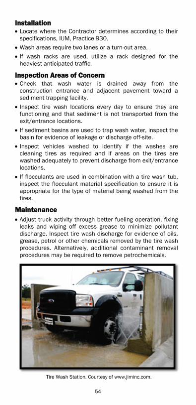
IInstallation Locate where the Contractor determines according to their specifications, IUM, Practice 930.
Wash areas require two lanes or a turn-out area. If wash racks are used, utilize a rack designed for the heaviest anticipated traffic.
IInspection Areas of Concern Check that wash water is drained away from the construction entrance and adjacent pavement toward a sediment trapping facility. Inspect tire wash locations every day to ensure they are functioning and that sediment is not transported from the exit/entrance locations.
If sediment basins are used to trap wash water, inspect the basin for evidence of leakage or discharge off-site.
Inspect vehicles washed to identify if the washes are cleaning tires as required and if areas on the tires are washed adequately to prevent discharge from exit/entrance locations.
If flocculants are used in combination with a tire wash tub, inspect the flocculant material specification to ensure it is appropriate for the type of material being washed from the tires.
Maintenance Adjust truck activity through better fueling operation, fixing leaks and wiping off excess grease to minimize pollutant discharge. Inspect tire wash discharge for evidence of oils, grease, petrol or other chemicals removed by the tire wash procedures. Alternatively, additional contaminant removal procedures may be required to remove petrochemicals.
Tire Wash Station. Courtesy of www.jiminc.com.
54

Temporary Concrete Washout Facilities
Definition Used to contain concrete liquids when chutes, drums or hoses of concrete trucks or equipment are rinsed out after delivery to a construction site. Washout facilities store solids for disposal and prevent runoff of liquids associated with concrete activities from entering storm sewers or waterways.
Where Practice Applies All projects where concrete delivery trucks wash out at the project site
Why Practice Applies The Department, as an ILR40 permittee, is required “…to control waste such as discarded building materials, concrete truck washout, chemicals, litter, and sanitary waste at the construction site that may cause adverse impacts to water quality;… .” Highly acidic concrete washout is also a violation of the 35 IL Adm. Code statutes. The Contractor is obligated, under NPDES, to be aware of water pollution restrictions and by Article 107.01, Laws to be observed, to “…observe and comply with all Federal and State laws, local laws, ordinances, and regulations which in any manner affect the conduct of the work….” See Article 105.03(a) National Pollutant Discharge Elimination System (NPDES) / ESC Deficiency Deduction for further discussion.
Advantages Dedicated washout locations are easier to manage and restore after construction
Highly acidic effluent from concrete washout sterilizes soil and prevents proper establishment of vegetation
Disadvantages Removal of accumulated liquids is required prior to impending storms to prevent overflow of facility, otherwise cover facility
Washouts are only permitted in designated washout area(s), requiring travel to the washout site.
Installation Contractor is to inform the RE/T if trucks will use a washout or shall take the remaining material to another pour.
Contractor must submit plan of his/her proposed temporary concrete washout facility to RE/T for his/her approval prior to first concrete pour.
Prior to pour, discuss location and size of washouts.
55

Portable and Non-Portable Facilities o May require stabilized access for any of the washout
facilities. o To be located on level ground a minimum of 50 feet
from storm drain inlets, open drainage facilities, or water bodies. If this minimum distance is not attainable on smaller sites, the facility shall be located as far from the drainage facilities as possible. Additional inspections will be required at smaller sites which do not meet the minimum distance between drainage areas and washout facilities.
o Each facility shall be located away from construction traffic or access areas to prevent disturbance or tracking.
o Each facility shall have appropriate signage to inform equipment operators of the washout location.
Non-Portable Facilities o Impermeable sheeting must extend over entire
basin and berm to prevent escape of discharge. o Design non-portable facilities for the largest pour
expected. o Protect the area around the unit for 10 feet with
plastic under and around the unit to contain any spills or overflows.
o The facility shall be lined with 30-mil polyethylene liner and secured using sand bags, 6” wire staples or other anchors and shall be free of holes or tears.
Portable Facilities o Proprietary systems or impermeable bags per
manufacturer’s recommendation.
Inspection Areas of Concern Inspect liner for tears. An intact liner will ensure that concrete wastewater will not escape the washout facility. Otherwise, the practice benefit is negated.
Check area surrounding facility for signs of effluent escaping containment.
Verify that all washout facilities are located per SWPPP. Check that washouts are restricted to designated washout location(s).
Check depth of solids to ensure volume is sufficient for next pour.
Inspect washouts prior to pour to ensure sufficient volume is available to contain washout.
Inspect washout area following pour to evaluate effectiveness.
56
Maintenance Remove washout water from high volume facilities with a vacuum truck and dispose of properly. Do not discharge wastewater into the environment. (Note: acidity, not particulates, is environmentally hazardous)
Do not discharge washout water into the environment; facilitate evaporation of low volume washout water.
Clean and remove any discharges within 24 hours of discovery.
If effluent cannot be removed prior to anticipated rainfall event, place and secure a non-collapsing, non-water collecting cover over the washout facility to prevent accumulation and precipitation overflow.
Replace damaged liner immediately. Remove temporary concrete washout facilities when no longer needed and restore disturbed areas to original condition. Dispose of solidified concrete waste, considered Clean Construction or Demolition Debris (CCDD) as per the IEPA Act (415 ILCS5).
Incidence of Non-Compliance / Deficiency Deduction Deficiencies and deductions resulting from noncompliance with the ILR10 only apply to project sites disturbing one or more acres.
If the project is staged or there are adjacent projects and the sum of disturbed areas of the stages, or of all the adjacent projects is 1 acre, the project is covered under the ILR10.
ILR10 projects require that IONs be submitted. Washout overflow is an ION and a Deficiency Deduction.
Department policy is violated on projects disturbing 1 acre, where there is a washout overflow. The overflow will trigger a mandatory Deficiency Deduction as a storm water violation has occurred.
Specifications/Standard Drawing (STD) From IUM STD 654BW, 654ET and 654SB
57

Plan view for Barrier Wall and Straw Bale Facility
Barrier Wall Anchor Section Straw Bale Anchor Section
Each straw bale is to be staked in place using two 2”x2”x4’ wooden stakes driven flush to the top.
Plan view for Earthen Type Facility
Earthen Berm Anchor Section Subgrade Anchor Section
58
GGood Housekeeping
Construction Site Management
Construction site management involves inspection and documentation of the Contractor’s operations for potential pollutants of concern not directly related to land-disturbing activities.
The NPDES ILR10 and ILR40 Permits require construction site management for materials, waste disposal, equipment cleaning and maintenance, and litter management. The permits collectively define this aspect of the SWPPP as Good Housekeeping Practices and the prevention of illicit discharges into a project’s storm water system that could result from the above activities.
The purpose of the construction site management inspections are to ensure BMPs are in place to prevent discharge of pollutants from Contractor use areas or operation activities into a project’s storm water conveyances.
The inspector’s responsibility is to review the construction site management Good Housekeeping activities in the SWPPP and as provided by the Contractor to ensure compliance with the ILR10 and ILR40 Permits.
The following are the construction site storm water Good Housekeeping activities that are required as part of a project’s SWPPP. The key factor in construction site management is to identify storage use and equipment locations that will minimize contact with storm water.
All construction site management measures must be discussed at the project pre-construction meeting. The implementation of Construction Site Management is the responsibility of the project Contractors (see BDE SWPPP Form 2342).
59
Material Delivery & Storage
DDefinition The implementation of BMPs to ensure materials are delivered and stored properly on-site and not cause adverse impacts to water quality.
Where Practice Applies All sites covered by the ILR10 Permit
Installation Acceptable BMPs include secondary containment, spill prevention plans, covering of material, inventory control, pallets, and employee training for proper material storage.
Have materials delivered to designated storage locations. Materials delivered to the project require proper labeling. The Contractor must provide the location and the storage BMPs to minimize contact with storm water.
Inspection Areas of Concern Inspect storage containers for proper labeling. Check for newly delivered or empty containers. Inspect secondary containment for any breach (holes, tears, spillage, etc.) of the controls around the storage locations that could allow discharge.
Inspect materials stored on pallets to ensure pallets are not in the flow path of any discharge areas and for evidence of spillage onto the pallets.
Inspect all partial containers of material to ensure containers are properly sealed and stored away from storm water.
Inspect materials stored adjacent to a building to ensure storm runoff from the roof will not contact the materials stored.
Inspect delivery areas and storage locations for evidence of rutting, soil displacement, spills, discharges from containers, and contamination of surrounding soils.
Maintenance Document the various types of materials delivered and their storage locations in the SWPPP.
Update the SWPPP anytime significant changes occur to material storage or handling locations and when they have been removed.
Cleanup spills immediately. Remove empty containers.
60
Solid Waste Management
DDefinition Solid waste management practices to prevent or reduce discharge of litter and construction debris into storm drains and waterways. The ILR40 Permit requires construction site operators to control waste that may cause adverse impacts to water quality.
Installation Designate a waste collection area(s) for the construction site. Identify the location(s) in the SWPPP.
Trash dumpsters must be covered, especially when rain is imminent, to prevent litter from being displaced by wind.
An adequate number of dumpsters should be available on the job site.
Do not place liquid waste (e.g., oil, fuel, solvents, paints) or chemicals (e.g., pesticides, curing compounds) in dumpsters designated for litter and construction debris.
Do not wash out dumpsters except in areas of proper water containment and management.
The Contractor should train employees and subcontractors in solid waste management practices.
Inspection Areas of Concern Inspect dumpster areas for trash outside the designated dumpsters.
Inspect inlets, outfalls and drainageways for litter, debris, containers, etc.
Inspect the area for evidence of liquid waste draining from dumpster.
Observe construction site for evidence of improper waste disposal compliance (e.g., trash, empty containers, containers located away from designated disposal sites).
The Contractor must ensure that neither liquid waste (e.g., oil, fuel, solvents, paints) nor chemicals (e.g., pesticides, curing compounds) have been placed in dumpsters designated for litter and construction debris.
Maintenance If containers are full, instruct the Contractor via the inspection form to have them emptied immediately.
Update the SWPPP anytime a Contractor’s trash management plan significantly changes.
Instruct Contractor to correct items discarded outside of designated areas.
61
Vehicle and Equipment Fueling, Cleaning and Maintenance
DDefinition Practices designed to minimize the discharge of chemicals, grease, oils, fuels, solvents and waste water from vehicle and equipment fueling, cleaning and maintenance activities.
Where Practice Applies
All sites covered by the ILR10 Permit. Pollution prevention practices for vehicle and equipment operations on a construction project are required in the ILR40 Permit. The Contractor provides details of proposed procedures to be incorporated into the SWPPP.
Advantages Minimizes probability of uncontained discharges Restricts area requiring remedial cleanup in the event of a spill
Disadvantages
Reduces flexibility to maintain and refuel equipment on site
Installation Contractor must designate all cleaning and fueling areas. Locate designated cleaning, fueling or cleaning areas a minimum of 50 feet away from concentrated flows of storm water, drainageways, and inlets.
No wash water is allowed to discharge into storm drains or drainageways without proper treatment.
Use containments or drip pans at the vehicle and equipment areas.
The Contractor must develop a spill control plan. Post signage at all designated vehicle and equipment fueling and maintenance locations.
Check the SWPPP and/or commitment file for any environmental conditions limiting cleaning or maintenance of equipment on-site.
Inspection Areas of Concern Check for evidence of oil floating or present in storm water conveyances.
Check for discoloration of soil and/or water. Check for evidence of equipment fluids on the ground.
62

MMaintenance Cleanup spills immediately. Contractor must provide documentation that spills were cleaned, materials disposed of, and impacts mitigated.
Update the SWPPP when a designated location has been removed, relocated, added, or required maintenance.
Any spills discharged through a drainage system will require the submission of an ION.
In the event of a spill into a storm drain, waterway or onto a paved surface such as a parking lot, street, driveway or other surface connected to the storm water drainage system, the owner of the fuel must immediately take action to contain the spill.
Once contained, cleanup the spill. As an initial step this may involve collecting any bulk material and placing it in a secure container for later disposal. Follow up cleaning will also be required to remove residues from paved or other hard surfaces.
Spill Kit. Courtesy of EnCAP, Inc. S ill Kit C t f E CAP I
63
Extended Work Cessation/Shutdown
Definition Work cessation/shutdown is the construction site condition where completed and unfinished construction areas are covered completely by temporary vegetation and erosion control materials during the reduced work time period.
Where Practice Applies Planned or unplanned shutdowns may result from seasonal work stoppages, weather related delays, or contractual disagreements.
Advantages Incorporating cessation/shutdown control practices can minimize the discharge of sediments and allow erosion controls to be in place for spring thaws and storm events.
The Contractor should coordinate work to ensure useful access to the entire site occurs as the shutdown procedure proceeds.
A properly scheduled work cessation/shutdown procedure will allow the landscaping and erosion control subcontractors adequate time to schedule crews to do work in an appropriate time-period.
The Contractor’s schedule of work must include a work cessation shutdown schedule, backed off the first expected frost date (see below). One schedule strategy is to wind down the project to full stabilization linearly (i.e. two months prior to first average frost date is the date of last new disturbance, by one month before the first average frost date 50% of what was opened one month prior is now stabilized, two weeks later another 25% of the project is stabilized). Consult Article 250.07 Notes for appropriate seeding dates.
In addition to properly installed BMPs and the implementation of a shutdown procedure, the most important item is a reasonable and well timed schedule. The schedule is typically agreed upon during the first week of work. Items discussed include the average first frost date and the specified seeding dates. Secure an acknowledgement from the landscape and erosion control subcontractors that they can and will adhere to the shutdown schedule.
The Contractor should not be allowed to continue construction work through the shutdown period, or to delay the landscape/ESC subcontractor and cite this as the reason the shutdown has not been completed. Using work activity in one area of the job to delay the start of the shutdown procedure is not allowed.
64

DDisadvantages Work area shrinks as shutdown erosion control is implemented
IInstallation Winter cessation/shutdown applies to any project not final- stabilized prior to winter.
The fact that a Contractor may be working somewhere on the project does not preclude general cessation/shutdown condition. Cover all erodible areas either temporarily or permanently. All other erosion control devices whose absence would generate sediments shall be in place.
Inspection Areas of Concern
Continued inspection and maintenance of ESC measures Spreading/protecting of all stockpiled topsoil Seeding of all exposed surfaces Cover or stabilize all erodible sites Clean out all sediment ponds, basins and traps Install and maintain perimeter control measures to minimize sedimentation potential
Install and maintain runoff control measures to minimize site erosion potential
Maintenance Maintain ESC during a shutdown. This includes winter shutdown and spring snowmelt prior to construction restart where the Contractor must install appropriate BMPs and provide timely regular maintenance.
Inspection frequencies during winter or project shutdown are as required under the ILR10 Permit.
The important aspect of winter shutdown inspection is to ensure there is limited opportunity for sediment and other pollutants to escape the project site.
Seeding is the most cost effective erosion control practice. Seeding must be laid down and mulched so the plants are viable before the first frost, through the shutdown, and are ready for the spring thaw. While snow cover is a viable winter temporary cover, spring will be a challenge if the seeding is not viable. Plants that are too young at first frost die. Most seeders are extremely busy late in fall. Therefore, a good approach to winter shutdown seeding is to seed as many areas as possible as close to the fall seeding start date as possible. Beginning Labor Day, remind the Contractor that winter is coming and shutdown should begin.
65

Illinois First Fall Frost. University of Illinois at Urbana-Champaign, Illinois
State Water Survey.
Illinois Last Spring Frost. University of Illinois at Urbana-Champaign,
Illinois State Water Survey.
66

NTU Water Columns
NTU Water Columns. Courtesy of WBK Associates.
DDefinition Turbidity and suspended solids are water quality parameters that reflect the level of sediment yield. Turbidity is an expression of the optical property that causes light to be scattered and absorbed rather than transmitted in straight lines through a sample. Turbidity in water is caused by suspended matter (clay, silt, finely divided organic/inorganic matter, algae, and other organisms) and is measured in Nephelometric Turbidity Units (NTU) by a portable field device.
Turbidity is an effective and inexpensive indicator of Total Suspended Solids (TSS). TSS provides a medium for accumulation and transport, is a parameter used to measure water quality as a concentration (mg/L) of mineral and organic sediment, and requires lab testing.
As turbidity increases within a stream environment, a potential for reduced photosynthetic activity may occur with a subsequent potential decrease in available oxygen necessary to support aquatic biota. Increased TSS may destroy both water supplies for human, animal and other wildlife consumption as well as feeding and nesting habitats.
Turbidity is an indicator of reduced beneficial water uses and can harm aquatic life. Suspended solids transport nutrients, pesticides, bacteria and other harmful substances.
Beginning with the next issued ILR10 Permit, the Effluent Limitation Guidelines (ELG) of 280 NTU will be required for projects that exceed 10 or 20 disturbed acres.
NTU W t C l C t f WBK A i t
67

Reporting & Resolving Deficiencies
PProviding the Results of your Inspection
1. Maintain a Friendly and Professional Manner a. Show an interest in the person’s problem and
communicate your intentions to solve it. b. Don’t let the person’s anger motivate you to retaliate. c. Do not take what the individual says personally.
2. Acknowledge that a Difficult Situation Exists a. Take complaints seriously. b. Use a soothing tone of voice to show sensitivity to the
other party. c. Express empathy by responding to what the person
says and feels. d. When an apology is in order, apologize for the specific
incident only.
3. Calm the Individual by Questioning and Verifying a. Ask questions to fully understand the problem. Never
assume. b. Give the person feedback to show you understand the
problem. c. Be sure both parties are on the same page.
4. Involve the Person in Solving the Problem a. Discuss alternatives and their consequences. b. Request suggestions for solving the problem and offer
assistance to correct the situation.
5. Handle the Problem a. Decide on a follow up action to ensure a resolution to
the problem.
Resolving Deficiencies
1. Work with the Contractor to Determine Repair Strategies and Time Lines
2. Present the Situation
a. Explain the situation with as few words as possible. Concise explanations spare the other party the anxiety of awaiting bad news.
b. Provide a short background about the events leading to the present situation.
c. Provide reasons why the situation occurred. Try highlighting that the person’s actions were not responsible for the situation.
d. Using the ‘good news first, bad news last’ scenario may appear patronizing.
e. Don’t belittle the bad news.
68

3. Allow the Person Time to Adjust a. The other party may need time to react. Allow this;
however, don’t facilitate long periods of silence. b. Try discussing the positive aspects of the situation,
this directs the interaction toward an optimistic outlook.
4. Accept the Person’s Reaction a. Allow the person to express his/her feelings and
opinions. b. If the person does not have a reaction, try talking
about how you would feel in a similar situation.
5. Demonstrate Acceptance of the Person’s Reaction a. You must observe and listen carefully to determine if
the person’s true feelings are being expressed. b. Remaining calm when anger, dissatisfaction,
embarrassment or confusion is presented should aid in directing the situation toward a more comfortable place.
c. Identify the other person’s emotion so that you may accept his/her reaction.
d. Avoid answering rhetorical questions, such as, “Don’t you think this is unfair?” Try restating the question to avoid answering and appearing biased; “I understand that you think this is unfair.”
e. Try providing an anecdote from a similar situation.
6. Restate Positive Points a. Once the initial reaction has subsided, aid the person
in putting the situation in perspective. b. Try expressing confidence in his/her abilities to meet
the challenge, and praise efforts.
7. Offer Assistance (but Don’t Direct) a. Reemphasize basic facts about the situation and
discuss steps to correct the problem. b. Never offer to assist the person in a capacity in which
you are not authorized. c. Inform the person that it may be necessary to submit
revised plans or seek legal help.
8. Clearly Express that Violations Must be Corrected a. Emotions can interfere with complete comprehension
of the problem/situation; therefore, repeat the required actions and their time frames.
69

b. In a professional and empathetic manner ask the person to restate the agreed upon solution.
9. Determine Deficiency Deductions a. Deficiency Deductions are applied only when a
Contractor fails to follow the contract. b. Failure to comply will result in Deficiency Deductions
but not necessarily an ION. i. Vehicles disregarding stabilized exits may
constitute an erosion control Deficiency Deduction. Sediment that is moved and enters an adjacent property or body of water will incur an ION.
10. Make a Date for Future Contact a. Allow the other party to contact you for further
discussion by providing a business card with appropriate contact information.
b. Confirm, in writing, the conclusions reached so all parties have a similar basis for their understanding of the situation.
The lessons were adapted from material written by the North Carolina Office of State Personnel, Division of Employee and Management Development, Personnel Development Center, in addition to ‘Erosion and Sediment Control Inspector’s Guide’ developed for the City of Jacksonville Water Quality Division Nonpoint Source Selection.
70
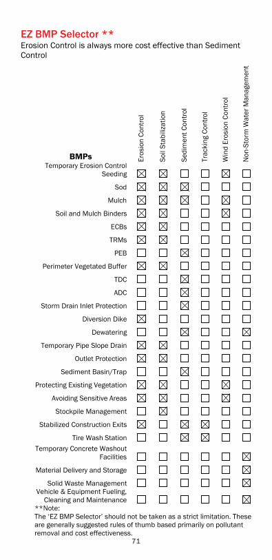
EZ BMP Selector ** Erosion Control is always more cost effective than Sediment Control
BMPs Eros
ion
Cont
rol
Soil
Stab
iliza
tion
Sedi
men
t Con
trol
Trac
king
Con
trol
Win
d Er
osio
n Co
ntro
l
Non
-Sto
rm W
ater
Man
agem
ent
Temporary Erosion Control Seeding
Sod
Mulch
Soil and Mulch Binders
ECBs
TRMs
PEB
Perimeter Vegetated Buffer
TDC
ADC
Storm Drain Inlet Protection
Diversion Dike
Dewatering
Temporary Pipe Slope Drain
Outlet Protection
Sediment Basin/Trap
Protecting Existing Vegetation
Avoiding Sensitive Areas
Stockpile Management
Stabilized Construction Exits
Tire Wash Station Temporary Concrete Washout
Facilities
Material Delivery and Storage
Solid Waste Management Vehicle & Equipment Fueling,
Cleaning and Maintenance **Note: The ‘EZ BMP Selector’ should not be taken as a strict limitation. These are generally suggested rules of thumb based primarily on pollutant removal and cost effectiveness.
71

Quick Reference
1’ = 1 ft ....... 1 foot
1” = 1 in ....... 1 inch
1 acre ....... 43,560 sq ft
¼ acre ....... 104’ x 104’
½ acre ....... 148’ x 148’
¾ acre ....... 181’ x 181’
1 acre ....... 209’ x 209’
72

Acknowledgements
The authors would like to thank the following sources for their critical information in shaping this field guide.
Thank you to:
Illinois Urban Manual: USDA Natural Resources Conservation Service
Illinois Tollway Erosion and Sediment Control Pocket Guide: University of Minnesota
Erosion Control and Stormwater Quality Field Guide: Colorado DOT
Field Manual on Sediment and Erosion Control Best Management Practices for Contractors and Inspectors by Jerald Fifield
Erosion and Sediment Control Inspector’s Guide: Developed for the City of Jacksonville by Grady Marchman
Special Thanks to those who wrote, edited and created this ESC Field Guide: Thomas Ripka, IDOT Matthew Sunderland, IDOT Peter Czosnyka, 2IM Group Katharine Owens, 2IM Group Richard Nowack, Quigg Engineering Rebecca Stocker, Quigg Engineering
Erosion and Sediment Control Field Guide for Construction Inspection
2IM Group, LLC produced this document with funding provided by IDOT. The cover photograph was provided by Rick Wanner of IDOT. Illustrations were developed by Katharine Owens of 2IM Group; photographs were provided as labeled or by Peter Czosnyka of 2IM Group. Peter Czosnyka was the principal author and project manager, with technical support from Katharine Owens and Richard Nowack of Quigg Engineering.
This document has been approved by the Illinois Department of Transportation and reflects Best Management Practices for erosion and sediment control for highway construction projects. Mention of trade names or commercial products, if any, does not constitute endorsement.
73