effect of air-gap on performance of fabricated …
TRANSCRIPT

Ninth International Conference on Advances in Steel Structures (ICASS’2018)
5-7 December 2018 - Hong Kong, China
Proceedings of the ninth international conference on Advances in Steel Structures Edited by Siu-Lai Chan, Tak-Ming Chan and Songye Zhu. Copyright © 2018 by The Hong Kong Institute of Steel Construction.
EFFECT OF AIR-GAP ON PERFORMANCE OF FABRICATED SLIM FLOOR BEAMS IN FIRE
Naveed Alam 1*, Ali Nadjai 1, Chrysanthos Maraveas 2, Konstantinos Daniel Tsavdaridis 3 and Faris Ali 1
1 Fire Safety Engineering and Technology (FireSERT), Ulster University, Belfast, UK E-mails: [email protected], [email protected], [email protected]
2 University of Liège, Liège, Belgium E-mail: [email protected]
3 School of Civil Engineering, University of Leeds, Leeds, UK E-mail: [email protected]
Abstract: Fabricated slim floor beams are produced by welding a steel plate to the bottom flange of an I-shaped steel section. The welded steel plate makes them structurally efficient and serves as a platform to support the steel decking of composite floor and the pre-cast concrete slabs. During their fabrication, an air-gap is induced between the steel plate and the bottom flange. Previous experimental investigations have shown that this air-gap has an influence on their thermal behaviour at elevated temperatures. Though the air-gap presence has an influence on their thermal performance, no investigations have yet been conducted to analyse its effects on their structural response in fire. This research investigates the effects of air-gap on structural response of fabricated slim floor beams in fire. During this study, finite element modelling is performed to simulate the response of fabricated slim floor beams and the predicted behaviour is verified against the available test data from literature. The validated finite element model is then employed to perform parametric studies to investigate the effects of the presence and size of the air-gap on their response in fire. Results obtained show that the presence of the air-gap has a significant influence on structural response of these beams at elevated temperatures. On the other hand, the size of air-gap has no or negligible effect on their thermal behaviour as well as on their structural response in fire. It was found that the presence of the air-gap restricts temperatures on the bottom flange and helps in achieving an improved fire resistance. As the presence of the air-gap is found to be helpful and beneficial, findings from this research can be used to develop similar designs for structural members as an efficient and inexpensive way to improve their behaviour in fire.
Keywords: Slim floor beams, Fire resistance, Air-gap effect, Finite element modelling, Composite construction
DOI: 10.18057/ICASS2018.P.043
1 INTRODUCTION Slim floor beams became prominent in the Nordic countries during late 1970s as they offer
numerous advantages over traditional composite beams with hanging steel sections [1]. Though the slim floor technology has recently got a wider acceptance, the art of shallow floor construction is being used since the 1790s [2]. Earlier, during the 19th century, filler joist type of shallow floor systems were frequently used [2]. The shallow floor construction was however forgotten and not much attention was paid till the 1970s when Hat beams and Thor
brought to you by COREView metadata, citation and similar papers at core.ac.uk
provided by Ulster University's Research Portal

N. Alam et al.
beams were introduced in the Nordic countries. Other designs of slim floor beams including the delta beams and the fabricated asymmetric slim floor beams followed these initial design types [1]. Slim floor beam construction was introduced in the United Kingdom (UK) in the 1990s [3]. Since their introduction, distinct designs of these flooring systems, including fabricated slim floor beams (FSFBs), are widely used by the construction industry. FSFBs are very common in the UK as they are easy to fabricate using existing steel sections and plates [3]. Like other types of shallow floor beams, FSFBs offer various advantages including a flat soffit and a reduced depth of floor. The flat soffit offers ease of installation for the hydraulic and electric services, while the reduction in floor depth reduces the structure height and the cost of cladding [3]. During the floor construction, the steel section is encased within the casted concrete. This concrete contributes towards their second moment of area and induces partial encasement keeping the steel section insulated in fire conditions. The concrete insulation helps in maintaining low temperatures on the steel section, hence, FSFBs like other shallow floor systems hold an inherent fire resistance of around 60 mins [4,5]. During their fabrication process, an air-gap is inherited between the bottom flange and the welded steel plate. This air-gap has a considerable influence on their behaviour in fire resulting in a temperature difference of around 350°C between the bottom flange and the welded steel plate [6]. Though experimental investigations are available on influence of this air-gap on their thermal response [7], any influence of the presence and size of the air-gap on the structural response of FSFBs in fire is still unknown. In this paper, the structural response of FSFBs is investigated and effects of the air-gap presence and its size are analysed.
2 AIMS AND OBJECTIVES The aim of this study is to investigate the effects of air-gap on the structural response of
FSFBs in fire. To achieve this, a detailed analytical model is established and validated by replicating the thermal and structural response of FSFBs from literature. The validated analytical model is then used to perform a parametric investigation to analyse the influence of the air-gap presence and its size on structural response of FSFBs in fire.
3 THE FIRE TEST During this research, a fire test conducted on a FSFB assembly is selected for the finite
element modelling (FEM) purposes. This fire test was conducted on a 5000 mm long FSFB assembly on the 14th of February 1991 at Warrington Fire Research Centre (WFRC) [8]. The test specimen was simply supported with a span of 4500 mm between the supports as shown in Fig 1(a). The steel section of the FSFB used for the test was formed using a 254x254x73 universal column (UC) and a 455 mm wide steel plate having a 15 mm thickness, Fig 1(b). Both the UC section and the steel plate were manufactured using S275 steel. Part of the floor surrounding the steel web between the flanges was cast-in-place concrete while the outer parts of the floor consisted of pre-cast concrete blocks 440 mm long, 140 mm wide and 215 mm deep [8]. These blocks rested on the welded steel plate as shown in Fig 1. The cube strength of the cast-in-place concrete was reported to be 30 MPa. Detailed instrumentation was performed to measure the temperatures and displacements during the test. Temperatures were measured using K-type thermocouples at seven distinct locations on the steel section of the test assembly [8]. In addition, arrangements were also made to measure the vertical displacements using Linear Variable Differential Transformers (LVDTs). The test assembly was exposed to standard fire for 90 mins and data was recorded in terms of temperatures and vertical deflections during the heating phase [8].

N. Alam et al.
Figure 1: Details of the FSFB assembly used during the fire test [8].
4 ANALYTICAL MODELLING Finite element modelling (FEM) for the FSFB assembly is performed using ABAQUS [9].
Though various analytical investigations are available in literature on the behaviour of shallow floor systems at elevated temperatures [10,11], they address the asymmetric slim floor beams (ASBs). Response of the FSFBs differs to that of ASBs due to the presence of air-gap between the welded steel plate and the bottom flange in the latter case. Hence, in this study, FEM is performed to analyse the response of FSFBs in fire and emphasis is made to highlight the influence of the air-gap presence and its size on their response. An analytical model is developed for the FSFB assembly used during the fire test described in section 3. The overall depth of the analytical model is 269 mm and has a span length of 4500 mm. Width of the assembly is 584 mm including 140 mm wide pre-cast concrete units on both sides of the steel section. The breadth of cast-in-place concrete, including the web of the steel section is 304 mm, Fig 1(b). Similar to the test assembly, the depth of the pre-cast units is kept at 215 mm while the depth of the cast-in-place concrete is kept at 254 mm during the FEM. Like the test, no concrete is modelled above the top flange. An air-gap of 1 mm is modelled between the welded steel plate and the bottom flange of the FSFB. During the FEM, the heating regime and boundary conditions are kept the same as those reported for the test while the non-linear thermal properties of the materials including the thermal conductivity, specific heat, and the density are taken as recommended by the Eurocodes [12]. During the thermal analysis, 8-node hexahedral solid linear heat transfer elements (DC3D8) are used to model the concrete and steel. Heat transfer through the surfaces is modelled via the surface film condition using convection coefficients for exposed and unexposed surfaces as 25W/m2K and 9W/m2K respectively, following the Eurocodes recommendations [13]. Any heat transfer via radiation from the unexposed surfaces is ignored. For exposed surfaces and for the cavity between the welded plate and bottom flange of the steel section, radiation is modelled using an emissivity of 0.7 as recommended by the Eurocodes [14]. The thermal analysis for the FSFB assembly is performed for a period of 90 mins against the actual furnace temperatures [8]. During the thermal analysis, a perfect contact is modelled at the interface of steel and concrete allowing full heat transfer as done previously [10,11,15].
The structural response of the FSFB assembly in fire is evaluated in two steps. During the first step, static loads are applied while in the second step, the FSFB assembly is heated using the validated thermal predictions obtained from the thermal analysis. All external loads

N. Alam et al.
applied during FEM are uniformly distributed and are same as those applied during the test having a degree of utilization of 0.46 of the FSFB [8]. Structural response of the FSFB assembly is measured in terms of vertical deflection at mid-span following recommendations of the British Standards, BS 476-20 [16]. During the structural analysis, the concrete part is modelled using 8-node linear brick elements (C3D8) while the steel part is modelled using 8-node linear brick elements with reduced integration (C3D8R). Both these elements were found to yield better results in comparison with other available element types. During the analysis, non-linear material models are employed for both steel and concrete. Steel is modelled using the ‘Von Mises plastic model’ while concrete is modelled using ‘the concrete damage plasticity model’ having a dilation angle of 55° for reasons mentioned previously in the references [10,11].
5 RESULTS FROM ANALYTICAL MODELLING Results from the analytical modelling are presented in the following:
(a) Thermal results after 90 mins of heating, section AA´
(b) Temperatures for thermocouple positions, section AA´
(c) Temperature difference between bottom flange and the welded steel
plate at section AA´
Figure 2: Thermal behaviour, FEM predictions vs test data.
0
200
400
600
800
1000
1200
0 30 60 90
4
3
2
1
T(°C)
t (mins)0
200
400
600
800
1000
1200
0 30 60 90
T(°C)
t (mins)
N. Alam et al.
5.1 The Thermal Results The thermal behaviour of FSFB is analysed in terms of temperatures for four
thermocouples at section AA´. Thermal predictions from FEM for these thermocouple positions are presented in comparison with the test data in Fig 2. Thermocouple positions 1, 2 and 3 represent the middle parts on the welded steel plate, bottom flange and web respectively, while thermocouple position 4 represents the middle part on the right half of the top flange as shown in Fig 1(c). The temperature profiles obtained at the end of the 90 mins from the FEM analysis are presented in Fig 2(a) for section AA´. It is seen that a higher temperature gradient is observed across the section. Temperature differences due to the presence of the air-gap between the welded plate and bottom flange can also be seen in Fig 2(a). The thermal predictions from the FEM are plotted against the reported test data [8] for the selected position of thermocouples in Fig 2(b) which gives a good agreement with the test data. A significant temperature difference exists between the thermocouples on the welded steel plate and the bottom flange as shown in Fig 2(c). This temperature difference is approximately 400°C after a fire exposure of 30 mins for the test data and as predicted by FEM.
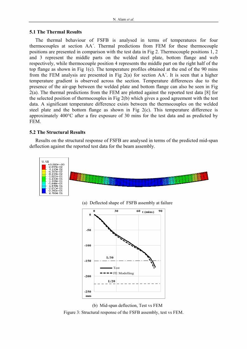
5.2 The Structural Results Results on the structural response of FSFB are analysed in terms of the predicted mid-span
deflection against the reported test data for the beam assembly.
(a) Deflected shape of FSFB assembly at failure
(b) Mid-span deflection, Test vs FEM Figure 3: Structural response of the FSFB assembly, test vs FEM.
-250
-200
-150
-100
-50
00 30 60 90
Test
FE Modelling
L/30
t (mins)
mm
L/20
N. Alam et al.
Deflected shape of the FSFB at failure is shown in Fig 3(a) which shows the deflection is maximum in the middle and gradually reduces towards the supports. The predicted mid-span deflection from FEM is plotted against the test data in Fig 3(b). Deflection results from FEM are in very good agreement with the test data. Deflection-based failure criteria for beams is defined by the British Standards (BS 476-20) in terms of the maximum deflection and the maximum rate of deflection as given in Eq. (1) and Eq. (2) respectively [16]. During the test, the FSFB assembly offered a fire resistance of 83 mins, while during the FEM, it offered a fire resistance of 81 mins. In both cases, failure initiated by exceeding the limits for the rate of deflection given by Eq. (2).
L/20 (1)
L2/9000d (2) where, L is the clear span of the specimen: d is the depth of the beam, the distance from top to the bottom. Failure criteria in Eq. (2) are only applicable when the deflection has exceeded L/30.
Predictions from the FEM and their agreement with the test data shows that the FEM method used during this study envisages the response of FSFBs at elevated temperatures with considerable accuracy. Hence, the proposed method is used to conduct a parametric study to investigate the effect of the air-gap and its size on response of FSFBs in fire.
6 PARAMETRIC ANALYSIS Influence of the air-gap on response of FSFBs in fire is analysed through a parametric
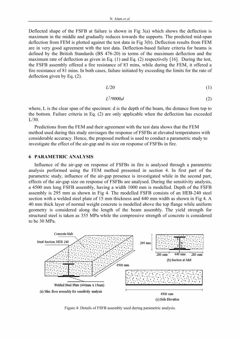
analysis performed using the FEM method presented in section 4. In first part of the parametric study, influence of the air-gap presence is investigated while in the second part, effects of the air-gap size on response of FSFBs are analysed. During the sensitivity analysis, a 4500 mm long FSFB assembly, having a width 1000 mm is modelled. Depth of the FSFB assembly is 295 mm as shown in Fig 4. The modelled FSFB consists of an HEB-240 steel section with a welded steel plate of 15 mm thickness and 440 mm width as shown in Fig 4. A 40 mm thick layer of normal weight concrete is modelled above the top flange while uniform geometry is considered along the length of the beam assembly. The yield strength for structural steel is taken as 355 MPa while the compressive strength of concrete is considered to be 30 MPa.
Figure 4: Details of FSFB assembly used during parametric analysis.

N. Alam et al.
During the parametric study, thermal behaviour of FSFB is analysed and presented in terms of the temperatures predicted for five thermocouple positions shown in Fig 4(b). The thermal analysis for the FSFB assembly is performed for 120 mins against the standard fire exposure conditions, ISO-834 [18]. On the other hand, the structural response is of FSFB is analysed in terms of the mid-span deflection [16]. Parametric analysis is conducted for FSFBs without the air-gap and with air-gaps of 0.5 mm, 2.2 mm, 4.1 mm and 10 mm. For all FSFBs, the structural response at elevated temperatures is analysed for a degree of utilization of 0.46, similar to the approach used during the experimental programme in the references [6,7].
6.1 Presence of the Air-gap and its Effect Effect of the air-gap presence on thermal behaviour of FSFBs is investigated by
modelling two beam assemblies with similar geometric properties as described in the above section. The first assembly is modelled without an air-gap ensuring the material continuity, while the second assembly is modelled with an air-gap of 0.5 mm between the welded steel plate and the bottom flange. Thermal predictions for both FSFB assemblies after an exposure of 120 mins to standard fire are presented in Fig 5. For FSFB assembly without the air-gap, the temperature difference for position 1 and 2, representing the welded steel plate and the bottom flange, is very low. A maximum temperature difference of 33°C is predicted after 56 mins.
(a) Thermal gradient across the section of FSFB assembly without air-gap
(b) Thermal gradient across the section of FSFB assembly with air-gap
(c) Comparison for thermocouples on welded plate and bottom flange
(d) Comparison for thermocouples on web and top flange
Figure 5: Thermal comparisons for FSFB assemblies with and without air-gap.
0
200
400
600
800
1000
1200
0 30 60 90 120
ISO Fire
Plate with Gap
Plate without Gap
Bottom Flange withoutGapBottom Flange withGap
T(°C)
t (mins)
0
200
400
600
800
1000
1200
0 30 60 90 120
3
4
5
T(°C)
t (mins)

N. Alam et al.
On the other hand, for the FSFB with 0.5 mm air-gap thickness, the temperature difference is high and is predicted to be 375°C after 29 mins as shown in Fig 5(c). After 120 mins of fire exposure, the temperature difference for the latter case is 180°C which is still significantly higher as compared to that for the former case where this difference is 29°C for the same duration of fire exposure. Results from the analysis show that the presence of the air-gap has a high influence on thermal behaviour of FSFBs at elevated temperatures. It is seen in Fig 5(c) that the temperatures on the welded steel plate for the case with air-gap are significantly higher while those on the bottom flange are much lower compared to those predicted for the case without the air-gap. In case where there is no air-gap, the continuity of material and absence of air-gap ensures efficient heat transfer and the resulting temperature difference is very low. Hence, presence of the air-gap between the welded plate and bottom flange acts as an insulation and restricts the efficient heat transfer resulting in higher temperature differences between the welded plate and the bottom flange.
For both cases, a higher temperature gradient is observed across the section and the predicted temperatures reduce with the increase in distance from the exposed bottom parts towards the unexposed upper parts, Fig 5(a) and Fig 5(b). Influence of the air-gap presence reduces with the increase in distance from the bottom flange and eventually becomes negligible for the top flange as seen in Fig 5(d).
During the structural analysis of FSFBs, a load representing the degree of utilization of 0.46 is applied. The applied load is based on the capacity of the FSFB with 0.5 mm air-gap at ambient temperatures. The FSFBs are later heated using the temperatures obtained during the thermal analysis. The predicted structural response of both FSFBs in terms of the mid-span deflection is presented in Fig 6. It is seen that the FSFB without the air-gap displayed a fire resistance of 66 mins while the one with 0.5 mm air-gap displayed a fire resistance of 78 mins before reaching the failure criteria. In both cases, failure initiated by exceeding the limits of the rate of deflection given by Eq. (2). This shows that the presence of air-gap has a positive influence on the structural response of FSFBs and helps in achieving an improved fire resistance. In this case, an additional fire resistance of 12 mins was attained.
Figure 6: Effect of air-gap on structural response of FSFBs.
-250
-200
-150
-100
-50
00 30 60 90
Without Airgap
With Airgap
mm
t (mins)
L/30
L/20

N. Alam et al.
Presence of the air-gap seems helpful and beneficial; hence, similar designs can be proposed for other structural members as an efficient and inexpensive way to improve their fire resistance. Presence of the air-gap between the bottom flange and the welded steel plate restricts temperatures on the bottom flange, as a result, FSFBs retain their strength and stiffness offering a higher fire resistance.
6.2 Effect of the air-gap size Earlier, in section 6.1, it was found that the presence of the air-gap has a considerable
influence on response of FSFBs in fire. During this part of the parametric study, the effect of air-gap size on their response in fire is investigated. FSFB assemblies with air-gap thickness of 0.5 mm, 2.2 mm, 4.1 mm and 10 mm are modelled and investigated. The modelled FSFB specimens are similar to the FSFB assembly used in the first part of the parametric study except for the size of the air-gap. The FSFB specimens are exposed to standard fire for a period of 120 mins as before.
The thermal predictions obtained from FEM for the FSFB assemblies are presented in Fig 7. It is seen in Fig 7(a) that the thermal predictions for all five thermocouple positions are similar irrespective of the air-gap size. These findings are similar to the results obtained during an earlier experimental investigation [6,7]. This earlier experimental investigation was limited only to the thermal behaviour of FSFBs in fire [6,7]. During FEM, the effect of the air-gap size on the thermal behaviour of FSFBs is found to be negligible.
(a) Thermal predictions for FSFBs with different air-gap sizes
(b) Temperature difference between bottom flange and welded plate
Figure 7: Thermal comparisons for FSFB specimens with different air-gap sizes.
Temperature differences between the thermocouple position on the welded plate and the bottom flange are presented in Fig 7(b) for all FSFBs. These temperature differences are similar and in excess of 350°C after 30 mins of fire exposure. This similarity of results shows that the size of the air-gap has no or negligible influence on the thermal behaviour of FSFBs in fire.

N. Alam et al.
To analyse the effect of air-gap size on the structural response of FSFBs at elevated temperatures, FEM is performed for the FSFB assemblies with 0.5 mm, 2.2 mm, 4.1 mm, and 10 mm air-gap sizes. The structural response for FSFBs is evaluated for a degree of utilization of 0.46 based on the individual capacities of each FSFBs. Results of the FEM demonstrate that the effect of the air-gap has a negligible influence on the structural response of FSFBs at elevated temperatures. The FSFBs with 0.5 mm air-gap thickness exhibited a fire resistance of 78 mins while the ones with 2.2 mm, 4.1 mm, and 10 mm air-gap thickness exhibited a fire resistance of 79, 79.2, and 79.5 mins, respectively as shown in Fig 8. In all cases, failure initiated by exceeding the rate of deflection limits recommended by the British Standards, BS 476-20 [16]. Consequently, it can be concluded that the air-gap size has no or negligible effect on the structural response of FSFBs in fire.
Figure 8: Effect of air-gap size on the structural response of FSFBs in fire.
7 CONCLUSIONS This paper investigates the effects of air-gap on response of fabricated slim floor beams in
fire. It was found that the finite element modelling method used in this study can simulate the response of FSFBs at elevated temperatures with good accuracy. Presence of the air-gap has a considerable influence on the thermal behaviour of fabricated slim floor beams in fire. This air-gap acts as a layer of insulation, as a result, a higher temperature difference between the welded steel plate and the bottom flange of the steel section is observed. The air-gap presence has a larger influence on the bottom parts of these beams as compared to upper parts, the top flange and upper web. Though the presence of air-gap has a major influence on the thermal behaviour of fabricated slim floor beams in fire, the size of this air-gap has no or negligible effect on their thermal behaviour. Similarly, it was found that the presence of air-gap has a considerable influence on the structural response of fabricated slim floor beams in fire and results in an improved fire resistance. The size of the air-gap, on the other hand, was found to have no or negligible influence on the structural response of fabricated slim floor beams at elevated temperatures. Presence of the air-gap is found to be beneficial; hence, findings from this research can be used by fabricators and manufactures to propose similar designs for other

N. Alam et al.
structural members as an efficient and inexpensive way to improve their fire resistance without the use of fire protection materials.
REFERENCES [1] Lu, X. and Mäkeläinen, P., “Slim Floor Developments in Sweden and Finland”, Structural
Engineering International, 6(2), 127-129, 1996. [2] Maraveas, C., Wang, Y.C. and Swailes, T., “Thermal and mechanical properties of 19th century
fireproof flooring systems at elevated temperatures”, Construction and Building Materials, 48, 248-264, 2013. DOI: 10.1016/j.conbuildmat.2013.06.084
[3] Mullet, D.L., Composite Floor Systems, 1st edition, The Steel Construction Institute, London. UK, 1998.
[4] Newman, G. M., “Fire resistance of slim floor beams”, Journal of Construction Steel Research, 33(1), 87–100. 1995.
[5] Bailey, C. J., “The Behaviour of Asymmetric Slim Floor Steel Beams in Fire”, Journal of Construction Steel Research, 50, 235–257. 1999.
[6] Rackham, J.W., Couchman, G.H. and Hicks, S.J., Composite Slabs and Beams using Steel Decking: Best Practice for Design and Construction, 2nd edition, The Metal Cladding and Roofing Manufacturers Association and The Steel Construction Institute, London, 2009.
[7] Fellinger, J. H. H. and Twilt, L., “Fire Behaviour of Long Span Composite Floor”, Fifth International Symposium on Fire Safety Science, Melbourne Australia, March 3-7, 1093-1104. 1997.
[8] Report to Corus CSD, Slimflor Compendium, Document RT1147, Version 01. London, The Steel Construction Institute, 2008.
[9] ABAQUS, Finite Element Modelling Programme and Standard User’s Manual, Version 6.14, SIMULIA, 2017.
[10] Maraveas, C., Swailes, T. and Wang, Y., “A detailed Methodology for the Finite Element Analysis of Asymmetric Slim Floor Beams in Firez”, Steel Construction, 5(3), 191-198. 2012.
[11] Alam, N., Nadjai, A., Ali, F. and Nadjai, W., Structural Response of Unprotected and Protected Slim Floors in Fire., Journal of Construction Steel Research., 142, 44–54, 2018. https://doi.org/10.1016/j.jcsr.2017.12.009.
[12] BS EN 1994-1–2:2014. Eurocode 4: Design of composite steel and concrete structures - General rules — Structural fire design, European Committee for Standardization, 3. 2014
[13] BS EN 1991-1-2:2013 Eurocode 1: Actions on Structures, part 1-2 General actions – Actions on structures exposed to fire, European Committee for Standardization, 2013.
[14] BS EN 1992-1-2:2008 Eurocode 2: Design of concrete structures part 1-2 General rules – Structural fire design, European Committee for Standardization, 3. 2008.
[15] Maraveas, C., Tsavdaridis, K. D., Nadjai, A., “Fire Resistance of Unprotected Ultra Shallow Floor Beams (USFB): A Numerical Investigation”, Fire Technology, 53 (2), 609-627, 2017. doi.org/10.1007/s10694-016-0583-5
[16] BS 476-20, Fire tests on building materials and structures, Method for determination of the fire resistance of elements of construction (general principles), British Standards Institution, 1987.
[17] The Free Encyclopedia for UK Steel Construction Information. (2017), Fabricated Slim floor Beam Fire Tests, [online]. Available at: http://www.steelconstruction.info/Steel_fire_test_data.
[18] ISO 834-1, Fire Resistance Tests- Elements of Building Construction. Part 1: General Requirements, International Standards Organization, 1999.
