effect of altitude on radiator … of altitude. on radiator performance. ‘v. national advisory...
TRANSCRIPT
., .... -- -.---,.
. . .. ..“
.1
.
.. ,. ,. . .
.- ‘“{:~) . . .,..”,1 ,,. REPORT NO. 62.,
..
EFFECT OF ALTITUDE
.
ON RADIATOR PERFORMANCE.
‘v
.
NATIONAL ADVISORY COMMITTEEFOR AERONAUTICS
,.,
.
PREPRINTFROMFIFTHANNUALREPORT
.
WAS131&TON ““GOVEBh~ PRINTINGOFFICE,
1s20
,.
.
.-
t“&
.’ -
.
https://ntrs.nasa.gov/search.jsp?R=19930091123 2018-06-20T22:25:44+00:00Z
“*
.
,
REPORT No. 62
ON
●
EFFECT OF
RADIATOR
ALTITUDE
PERFORMANCE
v
NATIONAL ADVISORY COMMITTEEFOR AERONAUTICS ‘
PREPRINTFROMFIFTHANNUALREPORT
“v
WASEINGTOStlovEBNMENT ~G OFFICE
1920

.
*
.
.
—,.—
REPORT No. 62
EFFECT OF ALTITUDEON RADIATORPERFORMANCE
By W. S. JAMES ~ S. R. PARSONS
.
●

.
●
REPORT No. 62.
EFFECT OF ALTITUDE ON RADL4TOR PERFORMANCE.lBy W. S. JAMES AND 8. R. PABSONS.
Ms-uME
A an airplane rises to high altitudw the $e~ease ~ the dmsib and the temperature oft~e ah have important effects on the performan~_ of the radiator.
The effect of the lower temperate tends.~ ~cre- the heat tr~sfer in proportion tothe increase of the mean temperate differ~ce between the water ti the radiator and the airthrough which the radiator passes.
The decreaee in density of the air reduces the:m= of air passing through the radiatorfor a given plane speed, and thus tends to decrease the heat transfer by an amount corresponding(but not proportional) to the decrease in densi~.
Since head resistance is proportional to d~ty of the air, the effect of decrease in densityis to reduce the head resistance by an amount proportional to the decrease of density.
The combined effect of density and tempemture changes is td decrease the heat transfer,but head resktanm is decreas~ more rapi~y, and for the higher plane speeds the figure ofmerit is, in general, ~we~d. On the other hand, at the higher altitudes ordy half (or evenless) of the cuoling capacity maybe required.
lf the performance of the radiator at the ground is lmown (from laboratory tests or other-wise), the density of the air and the”temperature dHerence between air and water at an alti-tude may be estimati from data conta~~ ~ the CUHWS of plote 1, 2, ~d 3 and from theconditions uder wMA the airpl~e is ~ be w@j =d with this information at hand thep~ormance of ~ radiator at an altitude maybe aWmatad for a particular speed of the airplaneat a particular altitude, as follows:
I. To obtain the energy dissipated, first fid the mass flow of air.tlmough the radiator atthe ground and at the desired speed and multiply this value by the ratio o’f the air densityat the altitude h the defity at the groud to obtiin the mass flOW of ~ at the aItitude.
Z. Now, from ~ rmtib of task at the gwmd obt~ the energy dissipated per 1000 F.~mperature difference between air and wa@r for the maas flow computed for the altitude,~d mtitiply this value by the estimated tempqature difference at the altitude divided by100 to obtain the energy actually dissipated at the altitude.
9 3. For head r@tan~ m~~ply the v~ue at~thegroud and at the desired speed by theratio of the de~ity at the ~titude b the density at the ground.
4. Horsepoww absorb~ is ~mpu~d - at the.groud by add~g to the head resistancethe quotimt obta~~ by divid~g the weight Pm squme foot of the radiatir fled with waterby the lif~drift ratio of the pl~e ~d m~tip@% this S~ by the plane speed ~d the propercmnwrsion f actor.
5. Figure of merit>as at the gro~d, is the @!!Z of the EKUXgydissipated ti the horsepowerabsorbed.
Plots NOS.4 ~ 7 show t~ effect of altitud~ OneRSIKYdissipated ~d me of merit fortwo typical r~a~% ~d PIOtNo. & which S1OWSthe ratio of air density at an altitude todtity at the gro~d, ~dica~ the proportio@. deme~ of head rdt~~ with increme ofaltitude for any type of radiator.,
IThis rez WESwfid~~y ~~t~ du~ W mrm KII-U Of S@d~* AmIMUffCPOW’ p~~ Report No. 23.
5
. --
.
_-
—
..
6 ANNUAL REPORT NATIONALADVLSO13Y COMMITTEE FOR AERONAUTICS.
INTRODUC1’ION.
The dhiency of a radiator for airplane engines depends primarily upon two factors:(I) Its capacity for dissipating heat and (2) its absorpfiop.~f engine power be~ause of the .geces- . .. .,,,sity of pushing it through the air (overcoming its head.rewstance) and of lifting and sustainingits weight.
At high altitudes both the density and the temperature of the air are less than at theground, and the change in these conditions has an important effect upon the performance ofthe radiator. The decrease in air temperature ,tinds to increase the cooling capacity, whilethe decrease in density of the air tends to decrease both the coding capacity and the absorp-tion of power for any given speed of the airplane. On the other hand, the power of the sngine, _... . . .. ......and consequently the heat to be dissipated, falls off .svithaltitude, so that at high altitudes agiven engine may be kept cool by a smaller ratliator than that required for the same conditions
-. -.
of speed ‘md climb nem the ground.PURPOSE.
.—.
The purpose of this report is, by showing the effect of temperature and density of the airon dissipation of heat and absorption of power, and with the use of available data on atmos-pheric conditions at altitudes, to present a method for. estimating the performanm. of +radiator under altitude conditions in terms of ita performance at the ground. A brief disctision will also be given of the relative cooling capacity required at altitudes and at the ground.
Since atmospheric conditions are continually changing, it will be evident that any estimateof performance at an altitude must be based upon assumed conditions, such, for example, asmean summer density and temperature of air, in addition to assumed requirementsof oparation,such.= the maximum allowable water temperature. Certain meteorological data have accordy . .ingly been included, in order to give such basis ~s ~-available for the assumptions that must
—
be made.DEFINITIONSOF-*. ““
The results of tests at the ground are expressed as follows:Free air speed (the speed of the airplane),.in miles per hour.Mizssjhu.r of air through the radiator, in pounds per second por square foot frontal area.Energy dwsipated (heat transfer), in horsepowty per square foot of frontal area per 100° F.
diflerenc~ between the temperature of the ent&ing afi and the average of the tcmporaturos of .. . ._the entering and leaving water, at ground. (At an altitude this timp~rature differmwc maybe modified.)
Head resistance, in pounds per square foot fronta~.area.Horsepower absoTbed,in hoRepow6i pei squ”ai%foot frontal area, ~&ding both that used “-“ ‘-
in overcoming head rwistance and that used in sustahing and lifting the weight of the radia@rand contained water, msnming for the airplane a lift-drift ratio of 5.4.
.... . . -.
Fi~re of merit isdefined as the ratio of the energy dissipated to the horsepower absorbed. . .. .h
BASISOF THBMETHOD.
The method of estimating radiator perfo~ance. under altitude conditions is has@ uponthe following laws:
1. Mass flow of air, for a given speed of the airplage, is proportional to the air density.2. Energj dissipated (rate of heat transfer), for a given mass flow of air, is independent
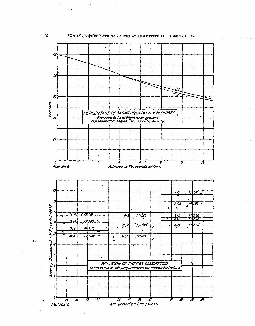
of air density. This fact is shown by a series of tests “conducted on a number of specimens in awind tunnel which was entirely inolosed in a steel tank so that the air could be partially ex-hausted. The range of air densities used corresponds to altitudw up to about 25,000 feet.Plot No. 10 shows the resulte of these tests.’
3. Energy dissipated for a given mass flow of a$ ‘~ay be regarded as proportional to thot.omperature difference indicated under “Detitiori& ‘of terms.” Several investigators have
1The samerwrlt ILMprevionelybeen observd for a singlecoppeztube with ah dendtk equal b md greaterthm atrmsphedc. SeaZrdt.—
dm Ver. dentmber In& 69; 48; p. 1750, Oct. ZF, M9.
—
40
m@lNATNLX7PHER/C TEMPL%XTUREAt know A/t/wales
1
.4U ‘
.?40OWXVG PO/N73AtW“busA/rI?udks. -
\MeanAnnual Valued
$ la
$
\
pw
$ N
m, \
N.>
% 4 8 &? 1% M H 28’P/otNa3. Alfhde in 730LAWIW3afFeef.
I I I I I
.
,,
3
m Ieomph.
>i
~ — — . — —
2~%
t~~ .p.n.
.&Qa
~ m.ph..
— — —Izol-n Ph.
M
●
8 4.8 R K .4 H 24
Plot No. 4. A/fiiude In 7hou.sands of f~t
a
Rodlufm- G-3 Un*UrA#pOSfrAm.. .
w
.%&’ @ mh,
‘8 — —
$.
—.
@ &.h ._ — — ——
m J- @h .
n120 aw h .
4 J t? a 20 u u
I& ~0. 6 . Aliifude 4?Tkw.son& &f-f.
a (m
SWI
.
,P;otNa.7 #ifu>em%wst&dsoff~.
1 I
.
EFFEOT OF AL’ITTUDE ON BADIATOB PERFORMANCE. 9
proposed empirkyd equations for the rate df heat transfer, in which the temperature diflerbnceoccurred to a power slightly diflerent from unity (in some cases ashigh as 1.2), but if the greatestvalue found were to be used, the difference bstween the result so obtained and that obtainedusing unity for the exponent, would be well within the range of uncertainty in atmosphericconditions at high altitudes. For the pr~ent purpose, tlpmfore, the linear proportionalitywill be used.
4. Head resistance, for a given free air speed, is proportional to the density of the air.This fact is in general use by aerodynamic engineers, and while it has been verified by a partof the experimental work on which this report is based, it hardly requires to be proved h~e.
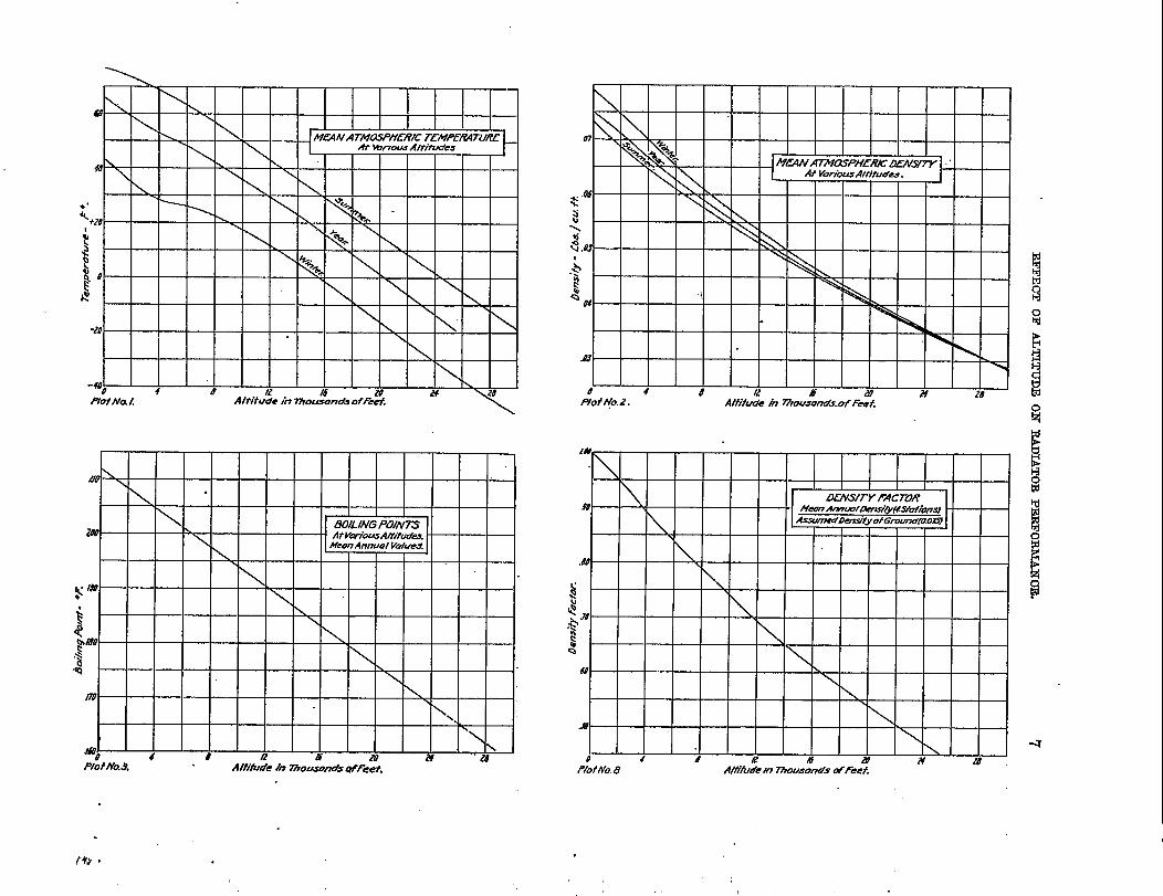
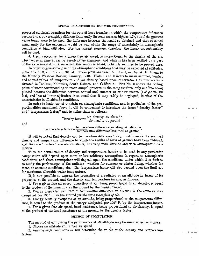
In ord?r to give some idea of the atmospheric conditions that may be expected at altitudes,plots Nos. 1, 2, and 3 are included, These plots are based on data given by W. R. @egg inthe Monthly Weather Retiew, January, 1918. Plots 1 and 2 indicate mean summer, winter,and annual values of temperature and air density based upon observations at four stationssituated in Indiana, Nebraska, South Dakota, and California. Plot No. 3 showa the boilingpoint of water corresponding to mean annual pressure at the saqp stations, only one line beingplotted because the difference between annual and summer or winter means (1.5°,at 25,000feet, and I- at lower altitudes) is so small that it may safely be neglec@dj in view of theuncertainties in all altitude conditions.
In order to inake use of the data on atmospheric conditions, and in particular of the pro-portionalities mentioned above, it will be convenient to introduce the terms “density factor”and t{temperature factor,” and to debe them M follows:
and
Density factor=air density at altitude ‘air density- at ground—
Temperature factor=temperature dillerence existing at altitude.temperature difference assumed at ground
It will be noted that density and temperature ~erence “at ground” denote the assumeddensity and temperature dii%rence to which the redts of tests at ground,,have been reduced,and that the (‘factors” are not constants, but vary with altitude and with atmospheric con-ditions.
Then the actual values of density and temperature facto~ to be used in any particularcomputation will depend upon more or Iws arbitrary assumptions in regard to atmosphericconditions, and these assumptions will depend Upori the conditions waler which it is deairadto study the performan~ of the rad.iatir-whether for summer or winter flying, wheth6r formean or extreme conchtlons, etc. The temperature factor will also depaid upon the limit setfor maximum allowable water temperature.
It is now possible to express the properties of a radiator at an altitude in terms of itspropeitiw at t~e ground, and the density and temperature facturs, as follows:
1. For a given free air speed, mass flow of air, being proportional to air density, is equalto the product of the mass flow it the ground by the density factor.
2. Energy dissipated per lUUO1? temperature difference an altitude is the same as thatdissipated per 100° F. at the ground jii the same mueg$ow of air.
3. Energy actually dissipated at an altitude, btig proportional ta tie temperature.differ-ence, is equal to the product of the mergy disipatid per 100° F. by tie t-perature factor.
4. For a given free air speed, head resistance, being proportional to air density, is equalto the product of the head resistance at the ground by the density factor.
METHODOF COMPUTATION.
The method of computing the performance .at an altitude m?y be summarized as follows:1. Choose an altitude and a free air speed.2. Aeaume such conditions SEwill de-e the valu-& of the density and temperature
factors.\
.-.
—.
.
10 A~N7JAL REPORT NATION+G ADVIS,ORY CO~MITTEE FOR AERONAUTICS.
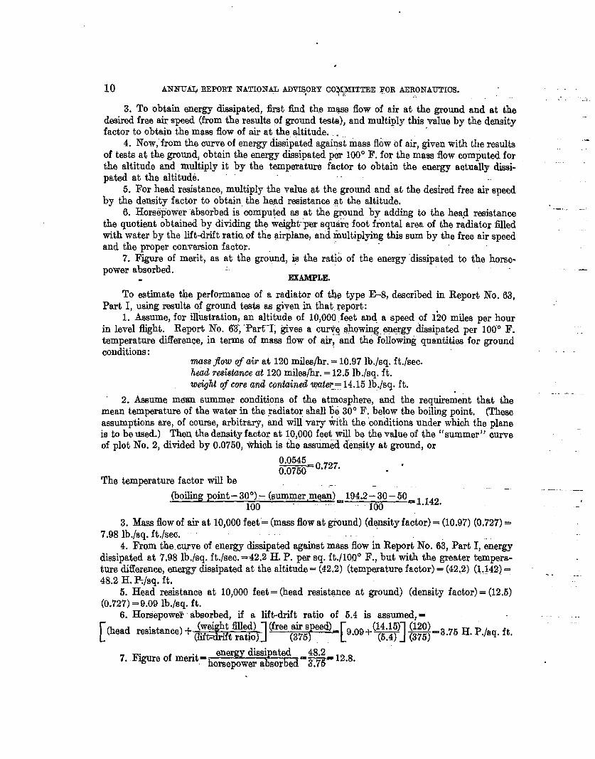
3. To obtain energy dissipated, tit find the m~ flow of air at the ground&aired free air speed (from the results of ground tests), and multiply this value byfactor to obtain the mass flow of air at the altitude.
-.
and at thethe density
4. Now, from the curve of energy dissipated agairistmass flow of ah, given with the r&ulh.-
of tests at the ground, obt~in the energy dissipated per 1000 F. for the mass flow computed forthe altitude and multiply it by the temperature factor to obtain the energy actually dissi- “-””pated at the altitud6.
5. For head resistance, multiply the value at the ground and at the desired free air speedby the density factor to obtain the head resistance .at the altitude.
6, Hore6p”ower‘absorbed is compu@d as at the ground by adding to the head resistan~ “–” ““the quotient obtained by dividing the weight-pr square foot frontal area of the radiator tiledwith water by the lift-drift ratio.of the airplane, and multiplying this sum by the free air speedand the proper conversion factor.
7. Figure of merit, as at the gro&d, is the ratio of the energy “dissipated to the horse-power absorbed. -. —
EXAMPLE.
To estimate me performance of a radiator of tie type E-8, described in Report No. 63,Part I, using results of ground tests as given in that report:
1. Assume, for illustration, an altitude of 10,000 feet and a speed of 1~0 mike per hourin level flight. Report No. 6$ ‘R-i% ‘1; @es a c~g showing energy dissipated per 100° F.temperature difference, in terms of mass flow of air, and the foIIow~ quantities for groundconditions: --
maw Jow of air at 120 miles/hr. = 10.97 lb./sq. ft,/sec.Led rwistmw at 120 mile@r. = 12.5 lb./sq. ft.weightof core and cuntaind water= 14,15 lb./sq. ft.
2. &+sume mwm summer conditions of the atmosphere, and the requirement that tie ‘“ ‘“-’-mean temperature of the watar in the radiator shall ~Q300 F. below the boiling point. (Theseassumptions are, of course, arbitrary, and will vary mth the conditions under which the planeis b be used.) Theu the density factor at 10,000 feet will be the value of the ‘fsummer”
—curve
of plot No. 2, divided by 0.0750, *hich is the assumed d’euity at ground, or
-00.727. ...
The temperature factor will be
(boiling point – 30°).- (mrnrner.rnqan~=194.2~30 – 50U1 142— .—. . ___
,100 100 “ “
3. Mass ilowof air at 10,000 feet= (mass flow at ground) (dqnsity factor)= (10.97) (0,727)=7,98 lb./sq. ft.lsec,
4. From the.curve of energy dissipated against mass flow in Report-No. 63, Part I, &ergydissipated at 7.98 lb,/sq. ft./see. =42.2 H. P. per sq. ft./lOOOF., but with the greater tempera-ture difference, energy dissipated at the altitude= (42.2) (temperature factor)= (42.2) (1,142)= ~. -_48.2 H. l?jsq. ft.
5. Head resistance at 10,000 feet= (head resistance at ground) (density factor)= (12,5)(0.727) =9.o9 lb./sq, ft.
6. Hors6moweT absorbed. if a liklrift ratio of 5,4 is assumed. = -.
[ ms%!wd(wP4&m%=’.7’ ‘.p.’s’+f’(head reskimce) + ‘w
7. Figure of m~t= ~e~ydissipated 48.2 12 s
horsepower absorbeda~ “ “

.
EFFECT OF ALTITUDE 07.? BADIATOB PERFORMAN03L 11
DESCRIPTIONOF CURVES..
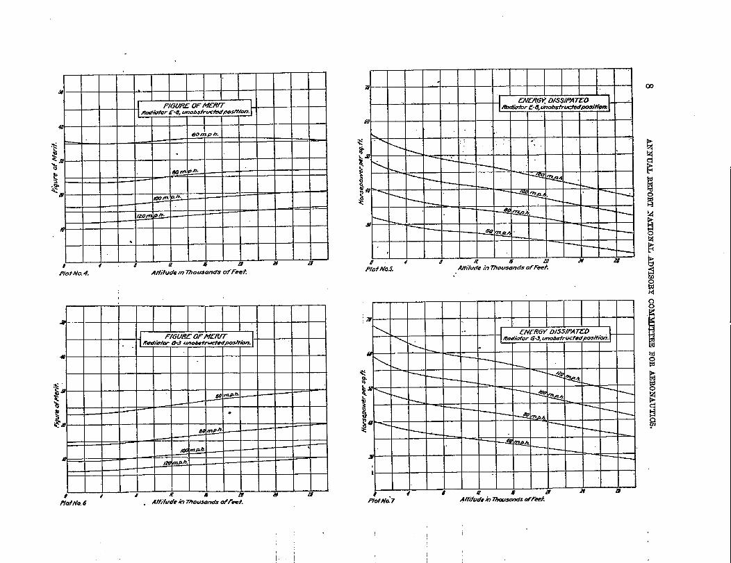
Plots Nos. 4 to 7 represent the properties of two types of radiator core at altitudes; plotsNOS.4 and 6, showing figure of merit, and plots Nos. 5 and 7, energy dissipated, in terms ofaltitude. The conditions and requirements assumed are mean summer dem+ityand tempera-ture of air and a mean water temperature 30° F. below the boiling point. The computationsare based upon data given in plots Nos. 1, 2, and 3.
Radiator 1%8 is made of flat hollow plates set edgetie to the air stream, and its perform-ance is typical of radiatom adapted to use inunobstructed positions-that is, in such positions .on the plane that the flow of air toward or away from the radiator is not obstructed by otherparts of the plane.
Radiator G-3 is a type of high heat transfer and high head resistance, adapted to use onlyin obstructed positions. Its properties are comput~d, however, only for the condition ofbeing placed in an unobstructed position, since the problem of determining head rw.istance inan obstructed position is too complex to be introduced into this report. (See Reports No.59, Genetal Anal@s of the Radiator Problem, and 61, Part II, Resistance Due to NoseRadiator.)
The curves indicate that while heat transfer falls off with altitude, the iigure of merit mayincrease slightly at the higher speeds. The general form of the curves is the same for both thetype of core suitable for unobstructed positions and the type suitable for obstructed positions.
Plot No, 8, based on mean summer density, shows a typical relation of “density factor”to altitude; and since head resistance is proportional to density, this plot also shows the relationof head resistance at a given free air speed to altitude. No curve of “temperature factor” isshown, because so many different assumptions may be made in regard to atmospheric condi-tions and operating requirements that a single curve could hardly be called typical. “Temperat-ure factor” cam easily be computed for various assumptions from data given in the plots oftemperature and boiling point against altitude.
DEGREEOF MASKINGREQUIREDAT ALTITUDES.
1’. HORIZONTAL FLIGHT.
If the radiator is to be partly masked at the higher altitudes, plot No. 9 may be wed togive an approximate idea of the degree of roasting desirable, in terms of the cooling capacityrequired at the ground for horizontaljlight.
Let a radiator be chosen of such a size that it will just cool the engine when flying at a givenspeed (shy, 120 malesper hour) horizontally, and close t.athe ground. Now the energy requiredto be dissipated, divided by the energy that the radiator is capable of dissipating, will representwhat may be termed the t‘effective area” of radiator required at an altitude, in square feet persquare foot required at the ground. ‘I’be adjective (‘effective” is used because the decreasein heat transfer caused by a partial masldng will depend not only upon the area of face covered,but upon the form of shutter used. The real indication of heat transfer will be given by themass flow of air, rather than by area.
The power of the engine, and consequ&tly the heat to be dissipated, may be assumedrou@y proportional to the air density (see Report No. 45, Part I), and an approximate valuemay be found by multiplying the energy dissipated at ground by the density factor. PlotNo. 9 shows the ratio of this required dissipation to the capacity for dissipation, as taken fromplots Nos. 5 and 7, and represents approximately the ratio of the “effective area” desirable atan altitude to that required at the ground, M the.rad.iatir is to keep the engine at a constanttemperature, These curves are plotted for a speed of 120 miles per hour, but are practicallyidentical with the curves for other speeds. This fact, and the small difference between thetwo curves plottad, seems ti indicate that the destiable degree of masking is a function of thealtitude, and practically independent of the type of core or of the speed.
.—
.
.
12
.
I
PERCENTAGE GFRADWOR CAPAClW7Z@71RdRe%wedh /..1 fligh+ new ground.
tiorse~nerofenghe bvrythgwifhdemify.
4 8 R @ a a 28
P/of No. 9 Altitude m 7%ousomfs of feet.
24A-7 M. .Lm .
18
$A -23 . # .L95 L
,. ● a
g {b “. ~ -4\ 0 Q . .F-5 M .’ij5 G-2 “ )?. Z.oa
tx
gfv . A ‘86;6 M+Z.14 m
> . D-jc; 7 “ /%.. /.60 “, w . B-9 M+Z.00 .
- M:,2.15 . “x
y L? 6= ~-3M 250 l“ 0 c: 7 . M..I.44
0
;0 0
.$ /JQ
.~
$8a
&lb RELATION OF fNERGYD/SS#!!TED~ ToM;SS F/o w. tiryingllensities for e/even Roo’ifftir6
G 4..
2.
4.04 AS .4$ .07 .Af ,L?f .(4J .07 ,& ,U3 .& .47
.— .—
Plot No. 10
EFFE13! OF ALTITUDE ON RADIATOR PERFoRMANcE. 13
IL OHANGFJ FROM 0LIU51NG TO HOBIZONT& FLIGHT. “
When the plane changes from maximum olimb to horizontal flight, its speed will be greatlyincreased (for some types of planm, about doubled), and this inorease in speed will involve aproportional increase in maw flow of air, and a corresponding (though not proportional) increasein heat transfer. This consideration alone would require a degree of masking that would insome cases approach 50 per cent of the eff.ectiveneesof the radiator at the altitude, but it hasnot been included in the computations for plot No. 9 because of a wide range of its variationwith di.fTerentplanes and their different uses. If the relation is known between the maximumclimbing speed and the horizontal speed when using the same engine power, then the massflow of air and the corresponding heat transfer dan be determined from the resulti of tests atthe ground, and the degree of masking that is desirable cm be found from the two rates ofheat transfer.
It may be well to note that no account has been taken of additional cooling from thesurface of the engine itself or from connecting pipes, caused by the Iowering of the air tempera-ture; and again let it be emphasized that mass flow of air gives the real measure of what hasbeen tamed “effective area.”
o # -.4