effect of axial loads on implant-supported partial · effect of axial loads on implant-supported...
TRANSCRIPT
J Appl Oral Sci. 610
ABSTRACT
www.scielo.br/jaos
Effect of axial loads on implant-supported partial ������������ ��������������������
Luis Gustavo Oliveira de VASCONCELLOS1������������ ���������2, Luana Marotta Reis de VASCONCELLOS3, ����������������������������������4
1- DDS, MS, Department of Dental Materials and Prosthodontics, São José dos Campos Dental School, São Paulo State University, São José dos Campos, SP, Brazil.2- DDS, MS, PhD, Department of Dental Materials and Prosthodontics, São José dos Campos Dental School, São Paulo State University, São José dos Campos, SP, Brazil.3- DDS, MS, PhD, Department of Bioscience and Buccal Diagnosis, São José dos Campos Dental School, São Paulo State University, São José dos Campos, SP, Brazil.4- Mech Eng, MS, Department of Mechanical Engineering, Institute of Science Technology - CETEC, São José dos Campos, SP, Brazil.
Corresponding address: Luis Gustavo Oliveira de Vasconcellos - Alameda Harvey C. Weeks, 14 - sala 09 - Vista Verde - São José dos Campos - SP - Brasil - 12223-830 - Phone: +55-12-3912 2342 - Fax: +55-12-3947 9010 - e-mail: [email protected] or [email protected]
�����������������!"��#$$%�&����'���������(�$#��#$!$�&�����)�������(�*$��#$!$
Objectives: The present study used strain gauge analysis to perform an in vitro evaluation of the effect of axial loading on 3 elements of implant-supported partial
����������������������������������������������������������������������������������������������������������������������������������������� ����������������������� ��������������� ������������������������������������������������!�����"#�$������������� ��������%&%������������������������������������������������������������ ����������������������������������������������%&%�������'�()*��+���������������',.*������ ������������������������� ��������������������������������,.�#/���������to implant 1, SG 02 and SG 03 mesially and distally to implant 2, respectively, and SG #5�������������������6��7���������������������������������������� ��������������/#�$�����!����������������������6#�����������������������������������������'8��9��%��;��7*����������� ��������������������������������������������<��������������� ��=��8$>?8����������@�����������������������������������A#�#)��=���������������������������������������������������������'�(#�###/*������������9�������������������������������������'"6B�5B�CD*����������;������������'55"�FF�CD*��$���������������������������������������������������'�(#�F5H*��%��������I������������������������������cylinder did not affect in the magnitude of microdeformation, but the axial loading location ��J���������������������
Key words: Biomechanics. Dental implants. Dental prosthesis. Implant-supported dental prosthesis.
INTRODUCTION
Occlusal overload has been given as the primary �������������&�������� �������������������implants and of implant-supported prostheses10,12. �����������������������������������������������factors such as: a) geometry – position and number of implants4,18,24,26,27,29, linear or off-set arrangement of the implants22,24, cantilever extension18,24, a displaced occlusal plane24, size of the occlusal table18,23,24, excessive height of the abutment/�������24; b) occlusion – parafunctional habits18,
bite force18,23, occlusal contacts6,27; c) load-bearing capacity of bone – bone density and quality28, primary mechanical stability24, healing time24; and d) technological – precision of the implant/abutment and abutment/prosthesis interfaces8,20,24, amount of preload24, and type of prosthetic retention8,9,24.
Occlusal loads are first introduced to the prosthesis, and are delivered to the bone/implant interface25; hence, the development and maintenance of the bone/implant interface is particularly dependent on the control of biomechanical loads. Bones carrying mechanical
2011;19(6):610-5

J Appl Oral Sci. 611
loads adapt their strength to the load applied on them by bone modeling/remodeling. The response ����������������������������� ��������������������������� ������������������� ���� ��� ��increasing the bone density or apposition of bone. On the other hand, fatigue micro-damage resulting in bone resorption may be the result of mechanical stress beyond this threshold7,12,30.
Compared to implant-supported total fixed prostheses, implant-supported partial fixed prostheses are more susceptible to the moment generated by occlusal loads, since they lack the ����������&������� ���<����24. Moreover, the posterior region of the oral cavity presents higher ������� ����������� ����� ���!����������������anterior region; additionally, bone height is limited by the maxillary sinus or the mandibular nerve. In a retrospective clinical analysis of the relation ������� ���� ��������� �� �������� ���� �������overload, Rangert, et al.24 (1997) found that 90% of implant fractures occurred in the posterior segment, supported by one or more implants, in association ����������������� ������������������������
Recent studies have investigated the stresses caused by implant-supported prosthesis fabrication methods, by varying the type of cylinder8,9,15,16. `������� ����� ������ ������ ����� �������������������������������&���������������������prostheses.
Strain gauge analysis has been used to evaluate stresses in implant-supported prostheses, both in vitro3,15,22 and in vivo9,16, under static1,4,26, and/or dynamic loads5. Depending on the site to be evaluated, strain gauges can be bonded close to implants4,9,22, on the implants1,19, on the abutments19,26, and on the metal structures of the prosthesis3,9,17.
���� w�������������������������������������the magnitude of peri-implant microdeformation of �����&�������� ����� �������� ������� �������from prefabricated and plastic cylinders subjected to axial loads.
MATERIAL AND METHODS
To simulate clinical conditions in a real-life arrangement, three internal hexagon type implants from mesial to distal: labeled 1, 2, and 3 (Conect AR; 3.75-mm diameter, 13-mm depth; Conexão Sistemas de Prótese, Arujá, SP, Brazil) ����� ��������� ��� ���� ������� �� �� �����������model consisting of a 70x40x30 mm3 rectangular polyurethane block (Polyurethane F16, Axson, %������+�����*�������������������������������(Young’s modulus of 3.6 GPa). One matrix that ������������������������������������������������& ������ ���� ������������� �� ������ ��� ��straight line in the polyurethane block. The distance
�����������������������������������������F����������������������������������������������(SG) (Figure 1).
Microunit abutments (Micro unit; Conexão ,������ ��� ������*� ����� ������� ��� �������������������"#�$�����!��������������������manufacturer’s manual torque driver (Torque driver; Conexão Sistemas de Prótese).
���� ������������� �� �������� ����� �� ��������resin (GC Pattern Resin; GC Europe N.V., Leuven, 9������*��������� '������������9���9������Goldschalgerei, Bremen, Germany). The 10 ����������������������� �� ���� ������������ ����� ���� �������� ����� ��������� �� ����Microunit abutment to eliminate the inevitable dimensional changes originating from impression procedures8�������������������������� ��������using plastic cylinders (Plastic coping; Conexão Sistemas de Prótese) and pre-machined cobalt-chromium cylinders (Machined coping; Conexão ,������ ��� ������*�� ���� ������������� �����sprued, invested, and cast using a cobalt-chromium alloy (Wirobond SG, Bego Bremer Goldschalgerei, Bremen, Germany). To avoid bias resulting from manufacturing conditions, random sets comprising ��������������������� �������������� ����������������������������������������� ����������������� /&������������� ���� ������������ ����������������� ���� �������� ���� ����� ��� ������ ���to damage the internal surface of the copings, ���������������������������������� ��������microscope to check for casting imperfections. The abutments received three-unit superstructures, and ����������������������������������������������������������������������������������������������� ��!��� ������������ ���� ������������������������������������������������������� �������������������w���������������������������through an explorer13�� ,������������� ���������������� ��������������������
Four strain gauges (SGs) (KFG-02-120-c1-//$6#%"�� ����� 7��������� I��������� %������������������*������ ��������������������� ����� ������������ ���� ����� �� ����� ���� ��methyl-2-cyanoacrylate adhesive (M-Bond 200; Vishay Measurements Group, Raleigh, NC, USA). ,.�#/���������������������w����������������/��,.�#"�����,.�#6���������������������������������
Figure 1- Positioning of the internal hexagon implants, ����������� ���������������������� �����
8<<����<��=������������ )����&��))�����)�������'=���)���>������(������������������(���
2011;19(6):610-5
J Appl Oral Sci. 612
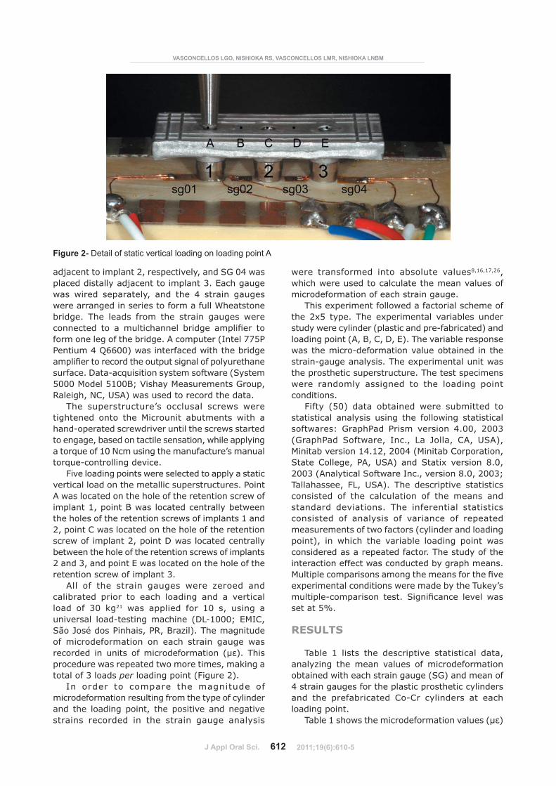
��w����������������"�������������������,.�#5����placed distally adjacent to implant 3. Each gauge ��� ������ ����������� ���� ���� 5� ������ �������������������������������������������������� ������� ���� ����� ���� ���� ������ ������ �������������� �� �� ������������� ������ ��������� ��form one leg of the bridge. A computer (Intel 775P ��������5����##*������������������������ �������������������������������������������������������������;���&��!�������������������',�����5000 Model 5100B; Vishay Measurements Group, =��������$%���,8*�������������������������
���� ������������@� ������� ����� ��������������� ��� ���� ��������� � ������� ����� ������&��������������������������������������������������� �������������������������������������a torque of 10 Ncm using the manufacture’s manual torque-controlling device.
+���������������������������������������������vertical load on the metallic superstructures. Point 8���������������������������������������������������/�������9��������������������� ���������������������������������������������/�����"�������%���������������������������������������������������"�������;��������������������� ���������������������������������������������"�����6�����������7���������������������������������������������������6�
8��� �� ���� ������ ������ ����� <����� ����calibrated prior to each loading and a vertical load of 30 kg21� ��� �������� ��� /#� �� ����� ��universal load-testing machine (DL-1000; EMIC, São José dos Pinhais, PR, Brazil). The magnitude �� �������������� �� ����� ������ ������ ����������� ��� ����� ���������������� 'CD*�� �����������������������������������������������total of 3 loads per loading point (Figure 2).
In order to compare the magnitude of microdeformation resulting from the type of cylinder and the loading point, the positive and negative strains recorded in the strain gauge analysis
����� ���������� ���� � ����� �����8,16,17,26, ��������������������������������������������microdeformation of each strain gauge.
�����������������������������������������the 2x5 type. The experimental variables under �������������������'��������������&�� �������*�����loading point (A, B, C, D, E). The variable response �����������&���������������� �������������������&���������������������������������������the prosthetic superstructure. The test specimens ����� �������� ������� �� ���� ������� �����conditions.
+����� ')#*� ����� ������� ����� � ������� ������������ ������� ����� ���� �������� ������������������ .�������� ����� ������ 5�##�� "##6�'.�������� ,�������� I����� ��� ������ %8�� �,8*��Minitab version 14.12, 2004 (Minitab Corporation, State College, PA, USA) and Statix version 8.0, "##6�'8����������,�������I�����������H�#��"##6��Tallahassee, FL, USA). The descriptive statistics consisted of the calculation of the means and standard deviations. The inferential statistics consisted of analysis of variance of repeated ����������������������'������������������������*�� ��� ������ ���� ����� ��� ������� ����� ���considered as a repeated factor. The study of the ������������������������������ ��������������������������������������������������������������������������������������� �����������@���������&�������� ����� ,����������� ������ ���set at 5%.
RESULTS
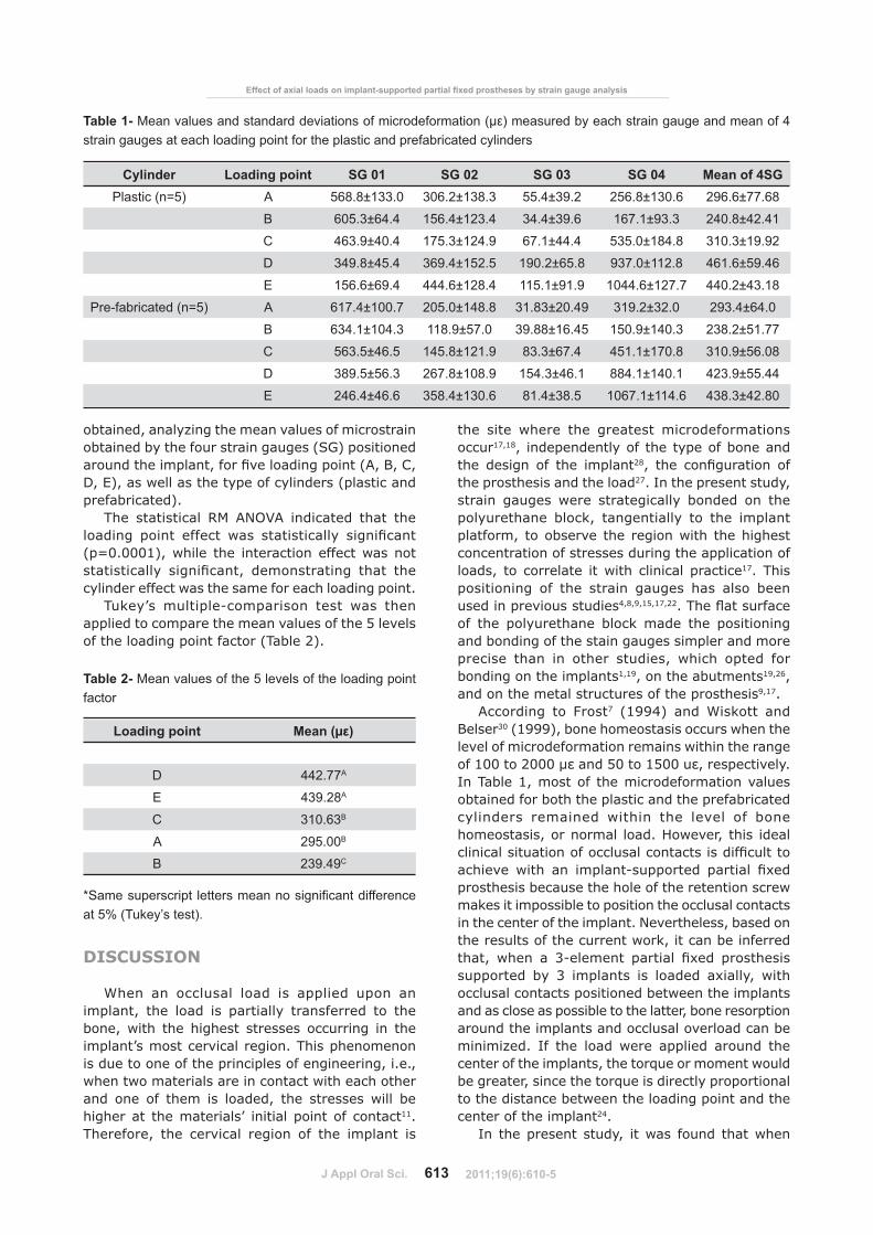
Table 1 lists the descriptive statistical data, analyzing the mean values of microdeformation �����������������������������',.*������������4 strain gauges for the plastic prosthetic cylinders and the prefabricated Co-Cr cylinders at each loading point.
�� ���/����������������������������'�D*�
Figure 2- Detail of static vertical loading on loading point A
?�@��@8�����B��������������?�@��@8���������������������
2011;19(6):610-5
J Appl Oral Sci. 613
obtained, analyzing the mean values of microstrain obtained by the four strain gauges (SG) positioned ��������������������������������������'8��9��%��;��7*�������������������������������'�����������prefabricated).
The statistical RM ANOVA indicated that the ������� ����� ������� ��� ������������ ����������'�(#�###/*�������� ���� ������������������������������������ ����������� ������������ ����� ���������������������������������������������������
�����@� ��������&�������� ���� ��� �����applied to compare the mean values of the 5 levels of the loading point factor (Table 2).
DISCUSSION
When an occlusal load is applied upon an implant, the load is partially transferred to the ��������� ���� ������� ����� ��������� ��� ����implant’s most cervical region. This phenomenon is due to one of the principles of engineering, i.e., �������������������������������������������������� ��� �� ����� �� ������� ���� ����� ����� ��higher at the materials’ initial point of contact11. Therefore, the cervical region of the implant is
���� ���� ������ ���� �������� ��������������occur17,18, independently of the type of bone and the design of the implant28�� ���� ����������� ��the prosthesis and the load27. In the present study, ������ ������ ����� ������������� ����� �� ����polyurethane block, tangentially to the implant ��������� �� ����� ���� ����������� �����������concentration of stresses during the application of ����� �� ��������� �������� ��������� ��������17. This positioning of the strain gauges has also been used in previous studies4,8,9,15,17,22������J����������of the polyurethane block made the positioning and bonding of the stain gauges simpler and more ������� ����� ��� ����� ������� ������ ����� ���bonding on the implants1,19, on the abutments19,26, and on the metal structures of the prosthesis9,17.
According to Frost7 (1994) and Wiskott and Belser30�'/BBB*�� ������������������������������������������������������������������������/##���"###��D�����)#���/)##��D���������������In Table 1, most of the microdeformation values obtained for both the plastic and the prefabricated ��������� ��������� ������� ���� ������ �� ������������������� �����`����������� ������������������������������������������������������������ ����� ��� �������&�������� �������� ������������ ����������������������������������makes it impossible to position the occlusal contacts in the center of the implant. Nevertheless, based on ������������������������������������ ����������������� ����� �� 6&�������� �������� ����� ��������������� �� 6� �������� �� ������ ��������� ��������������������������� �������������������and as close as possible to the latter, bone resorption around the implants and occlusal overload can be ������<���� I�� ���� ���� ����� �������� ������ ��������������������������������!����������������be greater, since the torque is directly proportional �������������� �������������������������������center of the implant24.
I�� ����������� ������ ������ ����� ����������
@(������ Loading point SG 01 SG 02 SG 03 SG 04 Mean of 4SG Plastic (n=5) A 568.8±133.0 306.2±138.3 55.4±39.2 256.8±130.6 296.6±77.68
B 605.3±64.4 156.4±123.4 34.4±39.6 167.1±93.3 240.8±42.41
C 463.9±40.4 175.3±124.9 67.1±44.4 535.0±184.8 310.3±19.92
D 349.8±45.4 369.4±152.5 190.2±65.8 937.0±112.8 461.6±59.46
E 156.6±69.4 444.6±128.4 115.1±91.9 1044.6±127.7 440.2±43.18
Pre-fabricated (n=5) A 617.4±100.7 205.0±148.8 31.83±20.49 319.2±32.0 293.4±64.0
B 634.1±104.3 118.9±57.0 39.88±16.45 150.9±140.3 238.2±51.77
C 563.5±46.5 145.8±121.9 83.3±67.4 451.1±170.8 310.9±56.08
D 389.5±56.3 267.8±108.9 154.3±46.1 884.1±140.1 423.9±55.44
E 246.4±46.6 358.4±130.6 81.4±38.5 1067.1±114.6 438.3±42.80
Table 1-������� ���������������������������������������������� ���������������� ������������strain gauges at each loading point for the plastic and prefabricated cylinders
Loading point �����DHIK
D 442.77A
E 439.28A
C 310.63B
A 295.00B
B 239.49C
Table 2- Mean values of the 5 levels of the loading point factor
�!���� "������"������������������������������at 5% (Tukey’s test).
8<<����<��=������������ )����&��))�����)�������'=���)���>������(������������������(���
2011;19(6):610-5

J Appl Oral Sci. 614
�������������������������������8��9��;�����7���������������������������������������������at the extremities, the largest microdeformations occurred in the closest strain gauges, indicating that the amount of load transmitted to the implant and the stresses generated in the bone depend �� ���� ������������� ���� ���� ������������ ������������I����������������������������������������������%���������������������������������implant, the greatest microdeformations occurred in the most distant strain gauges, indicating ����� ���� �������� ��� ���� ����������� ����� ����loaded (Table 1). These results suggest that the stresses generated by occlusal contacts located ������������������ ��������������������������partial prosthesis supported on three implants are distributed to the implants at the extremities, ������������������������� ����������������positioned close to the implants at the extremities concentrate in those implants.
Misfit at the abutment/prosthesis interface ��������������������� ���� �������������������&���������������������� �������� ����������������������������������������20. The precision of the interfaces may also negatively affect the load-bearing ability of the implant-supported prosthesis24, affecting the magnitude of the forces in the peri-implantar region25����������������������the superstructures can attribute to the impression technique, the control of laboratory analogues, or soldering method. The procedure that attempts to compensate for shrinkage or deformation, the ��&���������������������������������������directly on the abutment in polyurethane block8. Studies to evaluate the fit of the abutment/prosthesis interface have demonstrated that the precision of unitary metallic structures obtained ����� ����� �������� ��������� �� ������ ����� ����� ���������������������������2,14��̀ ���������������be noted that the care involved in handling multiple prostheses is very different from that involved in handling single ones, and the complexity of the laboratory procedures increases proportionally to ������� ��������������������
In this present study, the cylinder effect and ���� ���������������� ����� ����������� ����� ��statistically significant difference. This finding suggests that the type of cylinder, plastic or prefabricated, does not affect the magnitude of �����������������������������&�������������prosthesis is axially loaded, and that the behavior of �������������������������������������������������������������������������������������������Previous strain gauge studies have reported similar results8,9,15����������������������������������onto implants, made from plastic or prefabricated cylinders, producing the same magnitude of microdeformation during tightening of the retention
������ ������� ����������� ����������� �������plastic and prefabricated cylinders before8,9 and after15 the application of a dental ceramic.
With regard to the loading point effect, a ����������� ����������� ��� ����� '�(#�###/*��suggesting that symmetrical loading points, A versus E and B versus D, did not produce similar magnitudes ������������������������������������������������� ���������� ������ ��� �������� �������������� �����w���������������������������through an explorer. Therefore, the method used is not able to detect slight distortions of the prosthesis on the implant13, probably caused by casting ����������������������&���������������������������������������������������������������������������������������������������������attained by the cast metal rods in implant 3 may ���������������������������������������/������������������������������������������������ ������������������"�����������������������������������J���������������� ����������������������different magnitudes of microdeformation, even ����� ���� ���� ��� �������� �� �!��������� ����symmetrical points.
Limitations of the present model must be taken ���������������������������������������������investigation. This is an in vitro study based on �� ������� ����� ����� ����� �������������������� ������� �� ���� ������ ������� ���only proper strain measurements, but also 100% implant-model material contact. In vivo, additional variables like bone density, implant �� ����������� ��&�&�������������������������to be considered. The interimplant relationships ����������� �� �������&����� ����������� �� ������������� ������ ���� �� �� ��� �� ����������������������������������������� ��������������������������������������J�����������������of the superstructures did not represent the “real clinical situation”, variables such as cusp inclination, occlusal table and location, direction and magnitude of applied occlusal forces on the superstructures could change the results of this study.
CONCLUSION
Based on the obtained results, type of cylinder, plastic or prefabricated, did not affect in the magnitude of microdeformation under axial loading and the location of the applied axial loads affected the magnitude of microdeformation.
?�@��@8�����B��������������?�@��@8���������������������
2011;19(6):610-5

J Appl Oral Sci. 615
REFERENCES
1- Akça K, Çehreli MC, Iplikçioglu H. A comparison of three-���������� ������ �������� ���� ������� ����� in vitro strain gauge measurements on dental implants. Int J Prosthodont. 2002;15:115-21."&�%����89��9�������9��`������7��7���������� ������������������and polishing procedures on preload in prostheses using conventional “gold” and plastic cylinders. Int J Oral Maxillofac Implants. 1996;11:589-98.3- Castilho AA, Kojima AN, Pereira SM, Vasconcellos DK, Itinoche MK, Faria R, et al. In vitro������������������������������������������������&�������������������������������� ��������J Appl Oral Sci. 2007;15:241-6.5&� �������� �%�� 8���� ��� $����&��������� �������� �� ���������support for occlusal three-unit FPDs: a biomechanical analysis. Int J Periodontics Restor Dent. 2004;24:513-9.5- Çehreli MC, Akkocaoglu M, Comert A, Tekdemir I, Akca K. Human ex vivo bone tissue strains around natural teeth vs. immediate oral implants. Clin Oral Implants Res. 2005;16:540-8.6- Çehreli MC, Iplikçioglu H. In vitro strain gauge analysis of axial ������&�����������������������������������������������������Implant Dent. 2002;11:286-92.F&� +����`������@� ���� ���� ��@� ���������� ���������� ������������� ������ ��� �������� ��� ����������� 8����� >������1994;64:175-88.8- Heckmann SM, Karl M, Wichmann MG, Winter W, Graef F, Taylor �;��%������������������������������������������������������8��in vitro�������������&������������&���������������������dentures. Clin Oral Implants Res. 2004;15:466-73.9- Heckmann SM, Karl M, Wichmann MG, Winter W, Graef F, Taylor TD. Loading of bone surrounding implants through three-unit ������������������������������������&��������������� ������in vitro and in vivo strain measurements. Clin Oral Implants Res. 2006;17:345-50.10- Isidor F. Histological evaluation of peri-implant bone at implants subjected to occlusal overload or plaque accumulation. Clin Oral Implants Res. 1997;8:1-9.//&�I����+��I�J�������������������&�������� ����%����>����Implants Res. 2006;17(sp. Issue 2):8-18.12- Isidor F. Loss of osseointegration caused by occlusal load of oral implants. A clinical and radiographic study in monkeys. Clin Oral Implants Res. 1996;7:143-52.13- Kan JY, Rungcharassaeng K, Bohsali K, Goodacre CJ, Lang BR. %����������������������������������������������������������Dent. 1999;81:7-13.14- Kano SC, Bonfate G, Hussne R, Siqueira AF. Use of base metal �����������������������������������������������������������J Appl Oral Sci. 2004;12:337-43.15- Karl M, Rösch S, Graef F, Taylor TD, Heckmann SM. Strain �������� ������ ������� �� �����&����� �������� ��������� ��������superstructures. Implant Dent. 2005;14:157-65.
16- Karl M, Taylor TD, Wichmann MG, Heckmann SM. In vivo stress �����������������������������&������������&�������������+�;��J Prosthodont. 2006;15:20-4.17- Karl M, Wichmann MG, Winter W, Graef F, Taylor TD, Heckmann ,���I�J������������������������������������������������������������� �� �������� ����� �������� ��������� �� ���������2008;17:3-8.18- Kim Y, Oh TJ, Misch CE, Wang HL. Oclusal considerations in ����������������������������������������� ����������������������Clin Oral Implants Res. 2005;16:26-35.19- Maeda Y, Satoh T, Sogo M. In vitro differences of stress concentrations for internal and external hex implant-abutment connections: a short communication. J Oral Rehabil. 2006;33:75-8.20- May KB, Edge MJ, Russell MM, Razzoog ME, Lang BR. The ����������������������������������������������������������Dent. 1997;77:497-502."/&��������&,�����=��8��������������7��9���������>������������and oral tactile sensibility measured in partially edentulous patients �����I�I����������I�����>��������������I��������/BB)�/#�65)&)6�22- Nishioka RS, Vasconcellos LGO, Melo Nishioka LN. External hexagon and internal hexagon in straight and offset implant placement: strain gauge analysis. Implant Dent. 2009;18:512-20.23- Rangert B, Krogh PHJ, Langer B, Van Roekel N. Bending overload and implant fracture: a retrospective clinical analysis. Int J Oral Maxillofac Implants. 1995;10:326-34.24- Rangert BR, Sullivan RM, Jemt TM. Load factor control for implants in the posterior partially edentulous segment. Int J Oral Maxillofac Implants. 1997;12:360-70.")&�,�����,�����������%���������7��������J����������������������������� �������������������&���������������&�����������J Dent. 2002;30:271-82.26- Seong WJ, Korioth TWP, Hodges JS. Experimentally induced abutment strains in three types of single-molar implant restorations. J Prosthet Dent. 2000;84:318-26."F&�,��������=��,��������������`�����������>��I�J��������restoration type on stress distribuition in bone around implants: �������&��������������������������������I�����>��������������Implants. 1998;13:82-90."H&������,��,��������=�����������7�����������>����������`��I�J������ �� �������� ������ ���� ��� !������� �� ��������������� ������ ��� ��� ������ ��������� �� 6&���������� ������element analysis. Int J Oral Maxillofac Implants. 2003;18:357-68.29- Ueda C, Markarian RA, Sendyk CL, Laganá DC. Photoelastic analysis of stress distribution on parallel and angled implants after ��������������������������9��<�>����=���"##5�/H�5)&)"�30- Wiskott HWA, Belser UC. Lack of integration of smooth titanium �������� ��������� �������� ���� �� ������ ���������� ���the surrounding bone. Clin Oral Implants Res. 1999;10:429-44.
8<<����<��=������������ )����&��))�����)�������'=���)���>������(������������������(���
2011;19(6):610-5