effect of compression ratio and exhaust gas · pdf fileeffect of compression ratio and exhaust...
TRANSCRIPT

© 2014. M. Anandan, S. Sampath & Natteri M. Sudharsan. This is a research/review paper, distributed under the terms of the Creative Commons Attribution-Noncommercial 3.0 Unported License http://creativecommons.org/licenses/by-nc/3.0/), permitting all non commercial use, distribution, and reproduction inany medium, provided the original work is properly cited.
Global Journal of Researches in Engineering: A Mechanical and Mechanics Engineering Volume 14 Issue 7 Version 1.0 Year 2014 Type: Double Blind Peer Reviewed International Research Journal Publisher: Global Journals Inc. (USA) Online ISSN: 2249-4596 & Print ISSN: 0975-5861
Effect of Compression Ratio and Exhaust Gas Recirculation (EGR) on Combustion, Emission and Performance of DI Diesel Engine with Biodiesel Blends
By M. Anandan, S. Sampath & Natteri M. Sudharsan Sri Venkateswara College of Engineering, India
Abstract- The present investigation deals with combustion, emission and performance characteristics of a single cylinder DI diesel engine for biodiesel blends (J10, J20, J30, P10, P20, P30) with the optimum use of EGR system by the formulation of matrix analysis. Compression ratios like 17.5:1, 19:1, 20:1 were varied. The piston was modified by cold metal transfer (CMT) welding with the use of aluminium alloy on the piston bowl of the diesel engine. Tests were performed at different loading conditions and results were obtained. The performance study suggests that BTE was found to be increased with J20 CR20 and slight reduction with J20 CR20 E20 blend compared to diesel. Peak pressure was higher for J20 CR20 conforming better combustion characteristics over other biodiesel blends. Ignition delay were shorter for J20 CR20 and P20 CR20 blends with crank angle varying from 23.4 deg to 10.78 deg for J20 CR20 and 23.4 deg to 10.48 deg for P20 CR20 before TDC. NOx emission was increased with the increase in percentage of biodiesel blends. Significant NOx reduction in biodiesel blends were found with the use of EGR in J20 CR20 EGR20 and P20 CR20 EGR20.
Keywords: compression ratio, exhaust gas recirculation, biodiesel blends, combustion, emission.
GJRE-A Classification : FOR Code:
EffectofCompressionRatioandExhaustGasRecirculationEGRonCombustionEmissionandPerformanceofDIDieselEnginewithBiodieselBlends
Strictly as per the compliance and regulations of:
290501

Effect of Compression Ratio and Exhaust Gas Recirculation (EGR) on Combustion, Emission
and Performance of DI Diesel Engine with Biodiesel Blends
Abstract- The present investigation deals with combustion, emission and performance characteristics of a single cylinder DI diesel engine for biodiesel blends (J10, J20, J30, P10, P20, P30) with the optimum use of EGR system by the formulation of matrix analysis. Compression ratios like 17.5:1, 19:1, 20:1 were varied. The piston was modified by cold metal transfer (CMT) welding with the use of aluminium alloy on the piston bowl of the diesel engine. Tests were performed at different loading conditions and results were obtained. The performance study suggests that BTE was found to be increased with J20 CR20 and slight reduction with J20 CR20 E20 blend compared to diesel. Peak pressure was higher for J20 CR20 conforming better combustion characteristics over other biodiesel blends. Ignition delay were shorter for J20 CR20 and P20 CR20 blends with crank angle varying from 23.4 deg to 10.78 deg for J20 CR20 and 23.4 deg to 10.48 deg for P20 CR20 before TDC. NOx emission was increased with the increase in percentage of biodiesel blends. Significant NOx reduction in biodiesel blends were found with the use of EGR in J20 CR20 EGR20 and P20 CR20 EGR20. Keywords: compression ratio, exhaust gas recirculation, biodiesel blends, combustion, emission.
I. Introduction
n alternate fuel resource for IC engines is in great demand owing to various criteria. Usage of fossil fuel inhibits a scarcity of fossils and creates a
complication for renewal. In such a case, the use of biodiesel is growing at a rapid rate to replace the diesel fuel. Biodiesel is a term that describes a fuel comprised of mono-alkyl esters of long chain fatty acids derived from vegetable or animal oils. The vegetable oil based biodiesel has found a prominent place as an alternate fuel due to the depletion in the conventional fossil fuels [1], [2], [3]. The esterification of biodiesels from its major crude vegetable oil was used as a well-known biofuel. Early scientists have also conducted experiments on vegetable oils like (Thevetia Peruviana, Author α: Associate Professor, Department of Marine Engineering, Sri Venkateswara College of Engineering, Chennai, Tamilnadu, India.
e-mail: [email protected]
Author σ: Professor, Department of Automobile Engineering, Rajalakshmi Engineering College, Chennai, Tamilnadu, India.
Author ρ: Professor, Department of Mechanical Engineering, Rajalakshmi Engineering College, Chennai, Tamilnadu, India.
Neem oil) etc [4], [5]. In India, the large availability of Jatropha and Pongamia makes them a prime raw material for the production of biodiesel. Jatropha, is being spread across India as a vital crop to be cultivated due to the extensive advantages it inhibits [6]. Due to the similar fuel properties of biodiesel with the conventional diesel oil, it can be blended in varying proportions and used as an alternate fuel in Diesel engines [7]. Fuel consumption of biodiesel is slightly higher than conventional diesel due to lesser calorific value [8]. The exhaust gas of a diesel engine consists of
particulate matter [9]. All these gases pollute the atmosphere to a great extent that results in serious health hazards to human beings and also in the advent of precarious natural phenomenon like acid rain and greenhouse effect. One of the key method to overcoming this problem in engines is the use of an EGR system. Exhaust gas recirculation system is used as a hot mode by suffusing the varying percentage of burnt gases into the inlet port for reducing NOx emissions [10]. Exhaust gases resulting in lowering the emission of NOx by reduction of combustion temperature and excess oxygen [11]. As the working of this system is in direct concern to the environment, this system may be called an eco-friendly system. The methodology of EGR system is as follows.
II. Egr System
EGR is one of the efficacious methods in reducing NOx emissions in diesel engines. EGR has got its own limitations as at higher EGR rates the combustion is affected due to less availability of oxygen and hence increase in smoke emissions results in higher fuel consumption [12]. Hence a by-pass for the exhaust gas is provided along with the manually controlled EGR valve. The exhaust gas comes out of the engine during the exhaust stroke at a high pressure and is pulsating in nature. It is desirable to remove these pulses in order to make the volumetric flow rate measurements of the recirculating gas possible. For this purpose, smaller air box with a diaphragm is installed along the EGR route. A U-tube manometer is mounted
A
© 2014 Global Journals Inc. (US)
Globa
l Jo
urna
l of
Resea
rche
s in E
nginee
ring
()
AVol
1
Year
2014
ume
XIV
Issu
e V
II
Version
I
a high level of NOx along with HC, CO, CO2 and
M. Anandan α, S. Sampath σ & Natteri M. Sudharsan ρ

across the orifice in order to measure the EGR flow rate. Suitable instrumentation is provided to acquire useful data from various locations. Thermocouples are placed in intake manifold and exhaust manifold at various points along the EGR route. A matrix of test conditions is used to investigate the effect of EGR on exhaust gas temperature and exhaust smoke opacity. The schematic diagram of exhaust gas recirculation (EGR) system attached with the diesel engine is as shown in Fig. 1.
Increasing the exhaust pipe line length (15 metres) and placing the EGR system far away from the diesel engine reduces the exhaust gas temperature through natural convection. Manually controlled EGR valve was attached to pass the required amount of exhaust gas into the engine cylinder to combine with the intake air and is thus controlled accurately. Percentage of EGR was calculated using the following equation
© 2014 Global Journals Inc. (US)
Globa
l Jo
urna
l of
Resea
rche
s in E
nginee
ring
(
)A
Vol
2
Year
2014
ume
XIV
I ssu
e V
II
Version
I
Effect of Compression Ratio and Exhaust Gas Recirculation (EGR) on Combustion, Emission and Performance of DI Diesel Engine with Biodiesel Blends
Percentage of EGR =volume of air without EGR − volume of air with EGR
volume of air without EGR× 100
III. Transesterification Process
Transesterification is a suitable method for utilizing vegetable oils in DI diesel engine for long term applications without any major modifications and durability problems. Transesterification of vegetable oil enhances the quality of biofuel by reducing its viscosity. Transesterification is influenced by the reaction temperature, catalyst and stirring speed [13]. A two-step acid base process was used to prepare the biodiesel. In
the first step acid pre-treatment was used to extract the biodiesel from crude Jatropha and Pongamia oil followed by base transesterification using Methanol as a regeant; H2SO4 and KOH used as a catalyst. The physical and chemical properties of JME-Diesel; PME-Diesel was evaluated as per the IS 15607-2005 standards. The conversion of methyl esters from triglycerides with the presence of catalyst as represented in the following equation [14].
a) Fuel PropertiesJatropha Methyl Ester (JME) and Pongamia
Methyl Ester (PME) were mixed separately with diesel in varying proportions (10%, 20% and 30% by volume) and test fuels J10, J20, J30, P10, P20 and P30were prepared. The properties of neat diesel and biodiesel blends are presented in Table 1. Density and viscosity of biodiesel blends increases with increase in percentage volume of biodiesel due the higher molecular weight of fatty acids in biodiesel [15]. Respectively the density of biodiesel blends is higher than neat diesel oil. Density of higher jatropha and Pongamia blends is found to be 874 kg/m3 and 891 kg/m3. Kinematic viscosity of Jatropha and Pongamia blends is higher at J30 and P30 compared with diesel. Flash point of biodiesel blend is higher when compared with diesel. This is due to high vaporization temperature of biodiesel in air for combustion. Higher flash point enables storage of biodiesel blends safer than diesel and within the IS
5607-2005 standard limits [16]. Cetane number of biodiesel blends is higher when compared to diesel. Higher Cetane values of fuel enhance the combustion quality and hence smooth operation of the engine is guaranteed [17].
CH2OCOR1 CH2OH + R1COOCH3
CHOCOR2 + 3CH3OH CHOH + R2COOCH3
CH2OCOR3 CH2OH + R3COOCH3
Triglycerides Methanol Glycerol Methyl esters
H2SO4; KOH
Catalyst
IV. Experimental Setup
The experimental investigation were conducted on a single cylinder air cooled DI diesel engine. The maximum power extracted by an engine was 4.4 kW at a rated speed of 1500rpm. The specification of the engine is shown in Table 2. The experimental setup is as shown in Fig. 1. Cylinder pressure is measured using AVL GH14D Pressure Transducer. The pressure transducer is located in a hole drilled through the cylinder head into the combustion chamber. The sensing element consists of metal diaphragm, which deflects under pressure. AVL 365C angle encoder is used to convert the Analog signal into a digital electrical signal. DAQ card was

© 2014 Global Journals Inc. (US)
Globa
l Jo
urna
l of
Resea
rche
s in E
nginee
ring
()
AVol
3
Year
2014
ume
XIV
Issu
e V
II
Version
I
Effect of Compression Ratio and Exhaust Gas Recirculation (EGR) on Combustion, Emission and Performance of DI Diesel Engine with Biodiesel Blends
connected to the encoder to evaluate the electrical signals and determine the crank angular position. AVL 3066A02 Piezo Charge Amplifier is used to convert the electrical charge output of the pressure transducer into voltage. K type thermocouple was attached with diesel engine to measure the exhaust gas temperature. Electrical dynamometer is coupled to the engine by flexible coupling for measuring the brake power of the engine. It consists of a 5KVA AC alternator (220V, 1500rpm) mounted on the bearings and on the rigid frame for the swinging field type loading. The output power is directly obtained by measuring the reaction torque. Reaction force (torque) is measured by using a strain gauge type load cell. Panel board consists of Ammeter, Voltmeter switches and fuse, load cell indicator and temperature indicator. MRU delta 1600L Exhaust Gas Analyser was used to measure NOx, HC, CO and CO2 emissions. The emissions of CO (carbon monoxides) and HC (hydrocarbons) were measured by means of infrared measurement. AVL 415 Smoke meter is used to measure the percentage of smoke present in the exhaust gas. A fraction of the exhaust gas was sampled by means of a probe in the exhaust line and drawn through a filter paper. The resultant blackening of the filter paper was measured by a reflectometer and hence the opacity in the exhaust gas was determined. The list of instrumentation details is shown in Table 3. Exhaust gas recirculation (EGR) system externally fixed with diesel engine analysis the engine combustion and emission characteristics.
a) Testing ProcedureThe single cylinder direct injection diesel engine
was initially operated with neat diesel oil to maintain the wall temperature of the engine for proper combustion of biodiesel. Tests were performed for different loading conditions (0%, 25%, 50%, 75% and 100%) using JME and PME blends and for each loading condition theengine was allowed to run for 15minutes. Three sets of readings were taken for each test fuel. Varying compression ratio is attained in a constant compression ratio diesel engine through the modification of the bowl in piston as shown in Fig. 2 using aluminium alloy as an additive material by a low temperature CMT welding process. Compression ratio of 17.5:1, 19:1 and 20:1 were chosen for the present study. Exhaust gas recirculation is used in varying percentage by volume (10%, 20% and 30%). These three parameters were optimized by design of experiments (orthogonal array) and are shown in Fig. 3 and Table 3. Through this matrix approach the following conditions were selected for the optimized parameters: fuel blends (JME 20% and PME 20%), compression ratio 20:1 and Exhaust gas recirculation 20%.
V. Error Analysis
The maximum possible error in various measured parameters namely pressure, temperature, exhaust gas emissions, time, flow and speed estimated from the minimum values of output and accuracy of the instrument is calculated using the method proposed by (Moffat 1985). This method is based on careful specification of the uncertainties in the various experimental measurements. Instruments used for measuring various engine parameters as shown in Table 4.
If an estimated quantity S, depends on independent variables like (x1, x2, x3 …………xn) then the error in the value of S is given by
Where, , are the errors in the
independent variables. = square root of ((uncertainty of pressure transducer)2
+ (uncertainty of angle encoder)2 + (uncertainty of charge amplifier)2 +(uncertainty of smoke meter)2 + (uncertainty of NO)2 + (uncertainty of UBHC)2 + (uncertainty of CO)2 + (uncertainty of CO2) + (uncertainty of thermocouple)2 + (uncertainty of burette)2 + (uncertainty of load cell)2)
= square root of (((0.20)2 + (2)2 + (0.15)2 + (0.9)2 + (1.74)2 + (0.31)2 + (0.67)2 + (4.4) + (0.4)2 + (0.15)2 + (0.21)2) =square root of (8.831) =2.971%.
VI. Results and Discussion
a) Combustion i. Cylinder Pressure
The variation of cylinder pressure with respect to crank angle (CA) for diesel, biodiesel blends with different compression ratio and effect of EGR is shown in Fig. 4. for full load conditions. The peak cylinder pressure for diesel, J20 CR17.5, J20 CR20, J20 CR20 EGR20%, P20 CR17.5, P20 CR20 and P20 CR20 EGR20% was obtained as 75.729bar at 7°CA after TDC, 75.194bar at 7°CA after TDC, 77.987bar at 7°CA after TDC, 76.501bar at 7°CA after TDC, 75.523bar at 7°CA
2
122
2
22
1
1 ............
n
n
x
x
x
x
x
x
S
S
1
1
x
x
, 2
2
x
x
after TDC, 75.201bar at 7°CA after TDC and 74.511barat 7°CA after TDC respectively. For all engine loads, cylinder pressure gradually increases for compression stroke. It attains the peak value at 7°CA after top dead centre (TDC). The quantity of fuel burned was increased with increasing the engine load. If a peak pressure occurs very close to TDC that cause severe knock and affects the engine durability [18]. In this experiment, while operating with biodiesel blends the peak pressure

© 2014 Global Journals Inc. (US)
Globa
l Jo
urna
l of
Resea
rche
s in E
nginee
ring
(
)A
Vol
4
Year
2014
ume
XIV
I ssu
e V
II
Version
I
Effect of Compression Ratio and Exhaust Gas Recirculation (EGR) on Combustion, Emission and Performance of DI Diesel Engine with Biodiesel Blends
takes place after TDC and ensures safe and efficient operation. It is observed from the figure that the peak cylinder pressure with J20 CR20 blend was 2.53 bar higher than that of diesel. The reason for maximum cylinder pressure of J20 CR20 is increase in compression ratio. While engine was operated with EGR system, the peak cylinder pressure was found to decrease due to the increase in intake air temperature [19]. This in turn shortens the ignition delay period and hence results in lower peak pressure.
ii. Heat release rate theoretical consideration Rate of heat release developed inside the
cylinder during the combustion stroke was analyzed based on the in-cylinder pressure for various engine loads. The formula used to calculate the rate of heat release is given in Eq (1),
(1)
Where, γ-is the ratio of specific heats (Cp/Cv)
(Heywood 1988). The appropriate range of γ (for diesel)
heat release analysis is 1.3 to 1.35. is the heat
transfer in kJ/m3.degree, P-is the instantaneous cylinder pressure (bar), V-is the instantaneous cylinder volume (m3).
iii. Rate of Heat ReleaseThe change of heat release rate with respect to
crank angle (CA) for diesel and biodiesel blends with different compression ratio and the effect of EGR as shown in Fig. 5. for full load conditions. The peak heat release rate for diesel, J20 CR17.5, J20 CR20, J20 CR20 EGR20%, P20 CR17.5, P20 CR20 and P20 CR20 EGR20% was obtained as 69.854 kJ/m3deg, 65.326 kJ/m3deg, 62.481 kJ/m3deg, 64.427 kJ/m3deg, 79.791 kJ/m3.deg, 76.478 kJ/m3.deg and 70.079 kJ/m3.deg respectively. Maximum heat release rate for biodiesel blends occurs earlier than for diesel due to its shorter ignition delay period [20]. It is observed from the figure that, heat release rate gets reduced as the percentage of biodiesel blends increases. The reason for reduced heat release rate of biodiesel blends with EGR is due to higher temperature of intake air.
iv. Cumulative Heat Release RateThe change of cumulative heat release rate with
respect to crank angle (CA) for diesel and biodiesel blends with different compression ratio and the effect of EGR as shown in Fig. 6. The CHRR values were evaluated from the end of compression stroke to the beginning of expansion stroke. It is observed from the figure that JME blends shows higher cumulative heat release rate compared to diesel because of the presence of oxygen molecules in the biodiesel fuel. Meanwhile, CHRR gets lowered for biodiesel fuels with
EGR operation because of the reduction in combustion temperature.
v. Ignition DelayIgnition delay is the delay period between the
start of injection and the start of combustion. The ignition delay period of DI diesel engine was calculated by Eq (2).
(2)
τid- Ignition delay, EA- apparent activation energy, - universal gas constant, A, n-constants (depend on fuel injection and air-flow characteristics). The ignition delay for Jatropha, Pongamia methyl ester blends and diesel at full load condition is shown in Table 5. The ignition delay period in a diesel engine has an influence on both the engine design and its performance [21]. Ignition delay of Diesel, J20 CR17.5, J20 CR20, J20 CR20 EGR20%, P20 CR17.5, P20 CR20 and P20 CR20 EGR20% is 14.18°, 13.62°, 12.62°, 11.24°, 13.1°, 13.92° and 11.59° (CA) respectively. The ignition delay for biodiesel blends decreases with the increase in percentage of biodiesel due to the higher Cetane number of biodiesel compared with diesel.
b) Emission The emission and performance characteristic of
the IC engine is shown in Table 6.
i. NOx formation mechanism Thermal NOx is produced by the reaction of
atmospheric oxygen and nitrogen at elevated temperatures and is reported to contribute about 20% of the total NOx. Nitric oxide is the predominant oxide of nitrogen produced inside the engine cylinder. Nitric oxide (NO) and Nitrogen oxide (NO2) are grouped together as a NOx emission [22]. Mechanism of NOx
formation is proposed by Zeldovich was given by,
O + N2 = NO + N (3)
N + O2 = NO + O (4)
N + OH = NO + H (5)
ii. NOx emission The change of NOx emission for Diesel, J20
CR17.5, J20 CR20, J20 CR20 EGR20%, and P20 CR17.5, P20 CR20 and P20 CR20 EGR20% with brake power was shown in Fig. 7. At lower temperatures, nitrogen exists as a stable diatomic molecule but at higher temperature it becomes reactive. Hence higher temperature and availability of excess oxygen are two main factors which facilitate the formation of NOx [23].
dQ n
dθ=
γ
γ−1p
dV
dθ+
1
γ−1V +
dp
dθ
τid = Ap−nexp EA
R T
dQ n
dθ
The concentration of NOx emission increases with increase in engine loads. The NOx formation is higher with biodiesel blends than diesel oil. The NOX formation value for the Jatropha and Pongamia blends was found
R

© 2014 Global Journals Inc. (US)
Globa
l Jo
urna
l of
Resea
rche
s in E
nginee
ring
()
AVol
5
Year
2014
ume
XIV
Issu
e V
II
Version
I
Effect of Compression Ratio and Exhaust Gas Recirculation (EGR) on Combustion, Emission and Performance of DI Diesel Engine with Biodiesel Blends
to be 668 and 721ppm for J20 and 678 and 741ppm for P20 as optimum blend for 17.5 and 20 CR. This is due to higher Cetane number and availability of excess oxygen in the biodiesel inducing proper combustion [24]. NOx level decreases with the use of EGR system due to the higher specific heat of recirculated exhaust gas and reducing the excess oxygen in the intake charge. The NOx level of Jatropha and Pongamia with EGR system was found to be 534ppm and 612ppm.
iii. HC EmissionThe variation of hydrocarbon (HC) for diesel and
blends J20 CR17.5, J20 CR20, J20 CR20 EGR20%, P20 CR17.5, P20 CR20 and P20 CR20 EGR20% with brake power is shown in Fig. 8. Hydrocarbon emission from diesel engine acts as irritants and odorants while some are toxic carcinogenic. HC emission is due to the insufficiency of oxygen level to consume all the fuel during combustion. This is because of non-homogeneity of fuel-air mixture [25]. The HC emission varies from 13 ppm at part load to 30 ppm at rated load for diesel, while for J20 CR17.5 it varies from 4 ppm at part load to 24.59 ppm at rated load. For J20 CR20 it varies from 5.89 ppm at part load to 21.77 ppm at rated load, for J20 CR20 EGR20%, it varies from 5.32 ppm at part load to 32.34 ppm rated load, for P20 CR17.5 it varies from 12ppm at part load to 28.17 ppm at rated load, for P20 CR20 it varies from10.9 ppm at part load to 25.2 ppm at rated load and forP20 CR20 E20% it varies from 14.16 ppm at part load to 36.7 ppm at rated load. It is also observed from the figure that J20 CR20 has the lowest HC emission compared to other test fuel blends. Further it is perceived from the figure that, Increase in percentage of biodiesel blends and compression ratio decreases the HC emission due to complete combustion and availability of O2 in the biodiesel blends. Meanwhile inverse trends were detected with EGR system i.e. the HC emission increased with increase in percentage of EGR.
iv. CO EmissionThe variation of carbon monoxide (CO) for
diesel, J20 CR17.5, J20 CR20, J20 CR20 EGR20%, P20 CR17.5, P20 CR20 and P20 CR20 EGR20% with brake power was shown in Fig. 9. CO emission varies from 0.06% at part load to 0.154% of full load for diesel, while for biodiesel blends it varies from 0.07% at part load to 0.139% at full load condition for J20 CR17.5, for J20 CR20 it varies from 0.08% at part load to 0.121% at full load, for J20 CR20 EGR20 it varies from 0.085% at part load to 0.163% at full load, for P20 CR17.5 it varies from 0.05% at part load to 0.1% at full load, for P20 CR20 it varies from 0.066% at part load to 0.147% at full load, for P20 CR20 E20% it varies from 0.05% at part load to 0.124% at rated load. It is noted from the figure that, biodiesel blends produces lower CO emission when compared to diesel. It is concluded that increase in biodiesel blends and compression ratio results in
reduction in CO emission. However, CO emission increases with increase in the percentage of EGR. This is due to the overall reduction of excess oxygen resulting from EGR [26].
v. CO2 EmissionThe variation of carbon dioxide (CO2) for diesel,
J20 CR17.5, J20 CR20, J20 CR20 EGR20%, P20 CR17.5, P20 CR20 and P20 CR20 EGR20% with brake power is shown in Fig. 10. CO2 emission varies from 4% at part load to 8.7% at rated load for diesel, as for biodiesel blends 3.6% at part load to 8.1% at full load for J20 CR17.5, 3.8% at part load to 8.7% at rated load for J20 CR20, 4.2% at part load to 9% at full load for J20 CR20 EGR20%, 3.8% at part load to 8.6% at rated load for P20 CR17.5, 3.7% at part load to 8.8% at rated load for P20 CR20, 4.1% at part load to 9.2% at full load for P20 CR20 E20%. The increasing of CO2 emission with load is might be due to the higher fuel consumption of biodiesel blended and due to the excess presence of oxygen in biodiesel molecular structure [27].
vi. Smoke Opacity The variation of smoke opacity for diesel, J20
CR17.5, J20 CR20, J20 CR20 EGR20%, P20 CR17.5, P20 CR20 and P20 CR20 EGR20% with brake power is shown in Fig. 11. The smoke opacity varies from 0.35FSN at part load to 3.61FSN at rated load for diesel, 0.25FSN at part load to 2.24FSN at rated load for J20 CR17.5 and 0.39FSN at part load to 3.31FSN at rated load J20 CR20, 0.4FSN at part load to 3.49FSN at rated load for J20 CR20 EGR20%, 0.26FSN at part load to 2.8FSN at rated load for P20 CR17.5, 0.33FSN at part load to 2.62FSn at rated load for P20 CR20, 0.32FSN at part load to 4.24FSN at rated load for P20 CR20 E20%. It is observed from the figure that, smoke opacity decreases with increase of biodiesel in blends and compression ratio due to availability of O2 in fuel during diffusion combustion phase [29]. Meanwhile smoke opacity increases with increase in percentage of EGR this is due to present of carbon content.
c) Performance i. Brake Thermal Efficiency
Brake thermal efficiency is the efficiency of the diesel engine in which chemical energy of the fuel is extracted in the form of heat and utilized for mechanical work. The variation of brake thermal efficiency for J20 CR17.5, J20 CR20, J20 CR20 EGR20%, P20 CR17.5, P20 CR20, P20 CR20 EGR20% and diesel with brakepower is shown in Fig. 12. It can be seen that the brake thermal efficiency increased with increase in engine loads for all test fuels. It is observed from figure that the thermal efficiency of diesel is 28.81% at rated power and for J20CR17.5; P20CR17.5 is 27.9%, 27% respectively. It shows that efficiency of J20, P20 blends is slightly less compare with diesel this is due to lower calorific value. Brake thermal efficiency for J20 CR20, P20 CR20 is

© 2014 Global Journals Inc. (US)
Globa
l Jo
urna
l of
Resea
rche
s in E
nginee
ring
(
)A
Vol
6
Year
2014
ume
XIV
I ssu
e V
II
Version
I
Effect of Compression Ratio and Exhaust Gas Recirculation (EGR) on Combustion, Emission and Performance of DI Diesel Engine with Biodiesel Blends
31.7%, 30% due to the effect of increase in compression ratio. For J20 CR20 EGR20%, P20 CR20 EGR20%, the BTE is 30.89%, 29.37% which is reduced with the use of EGR. This is because of reduced amount fresh oxygen content present in the combustion chamber [29].
ii. Exhaust Gas TemperatureThe variation of exhaust gas temperature for
J20 CR17.5, J20 CR20, J20 CR20 EGR20%, P20 CR17.5, P20 CR20 and P20 CR20 EGR20% and diesel with brake power is shown in Fig. 13. The EGT varies from 263°C at part load to 456°C at rated load condition for diesel. 263°C at part load to 456°C at rated load condition for J20 CR17.5, 270°C at part load to 464°C at rated load condition and for J20 CR20, 244°C at part load to 430°C at rated load condition. For J20 CR20 E20, 271°C at part load to 470°C at rated load condition and for P20 CR17.5, 283°C at part load to 477°C at rated load condition for P20 CR20 and 243°C at part load to 435°C at rated load condition for P20 CR20 E20 respectively. Exhaust gas temperature gets decreased continuously as the percentage of exhaust gas recirculated into the engine is increased. It can be observed from the figure that exhaust gas temperature gets reduced considerably with EGR; resulting in lower combustion temperature and NOx emission.
VII. Conclusion
It is concluded from the results that,
The effect of increase in compression ratio increase the brake thermal efficiency, exhaust gas temperature, NOx emission and reduces the smoke opacity, CO emission and Unburned hydrocarbon emission.
NOx emission was higher for biodiesel and its blends due to higher in-cylinder temperature and availability of free oxygen in the fuel.
Smoke emission decrease due to availability of O2 in fuel during diffusion combustion phase.
Both HC and CO Emission decreases due to complete combustion and availability of excess oxygen in biodiesel blends.
Effect of EGR, Decreases NOx, EGT, thermal efficiency and increases Smoke, UBHC and CO.
NOx, Brake thermal efficiency, EGT gets reduced considerably by adopting EGR; meanwhile it slightly increases the Smoke, HC and CO emissions
Thus the usage of EGR to the optimum biodiesel blends reduces NOx emission and improves combustion characteristics providing an energy based fuel economy in diesel engines.
VIII. Abbreviation
J10, J20, J30 - Jatropha 10%, Jatropha 20%, Jatropha 30%
P10, P20, P30 - Pongamia 10%, Pongamia 20%, Pongamia 30%,
J20 CR17.5 - Diesel 80%-Jatropha 20% and compression ratio 17.5:1
J20 CR20 - Diesel 80%-Jatropha 20% and compression ratio 20:1
J20 CR20 EGR 20% - Diesel 80%-Jatropha 20% and compression ratio 20:1, Exhaust gas recirculation 20%
P20 CR17.5 - Diesel 80%-Pongamia 20% and compression ratio 17.5:1
P20 CR20 - Diesel 80%-Pongamia 20% and compression ratio 20:1
P20 CR20 EGR 20% - Diesel 80%-Pongamia 20% and compression ratio 17.5:1, Exhaust gas recirculation 20%
EGT - Exhaust gas Temperature
FSN - Filter smoke number
BTE - Brake thermal efficiency
CMT - Cold metal transfer
IX. Acknowledgement
Authors sincerely thank Mechanical Engineering Department, I.C. Engine Testing Laboratory, Sri Venkateshwara College of engineering, Chennai for their facility and support to carry out this research work. 18
References Références
Referencias
1. Gerhard Knothe, Biodiesel and renewable diesel: A comparison, Progress in Energy and Combustion Science xxx, 2009, 1–10.
2. Daming Huang, Haining Zhou, Lin Lin, Biodiesel: an Alternative to Conventional Fuel, Energy Procedia 16, 2012, 1874 – 1885.
3. Constantine Arcoumanis, Choongsik Bae, Roy Crookes, Eiji Kinoshita, The potential of di-methyl ether (DME) as an alternative fuel for compression-ignition engines: A review. Fuel 87, 2008, 1014–1030.
4. T. Kandasamy Kannan, Marappan Rakkiyanna Gounder, Thevetia Peruviana biodiesel emulsion used as a fuel in a single cylinder diesel engine reduces NOx and smoke. Thermal Science Vol. 15, No. 4, 2011, 1185-1191.
5. Md. Hasan Ali, Mohammad Mashud, Md. Rowsonozzaman Rubel, Rakibul Hossain Ahmad, Biodiesel from Neem oil as an alternative fuel for Diesel engine. Procedia Engineering 56, 2013, 625 – 630.
6. Dulari Hansdah, S. Murugan, L.M. Das, Experimental studies on a DI diesel engine fueled with bioethanol-diesel emulsions. Alexandria Engineering Journal 52, 2013, 267–276.

© 2014 Global Journals Inc. (US)
Globa
l Jo
urna
l of
Resea
rche
s in E
nginee
ring
()
AVol
7
Year
2014
ume
XIV
Issu
e V
II
Version
I
Effect of Compression Ratio and Exhaust Gas Recirculation (EGR) on Combustion, Emission and Performance of DI Diesel Engine with Biodiesel Blends
7. A. Murugesan, C. Umarani, R. Subramanian,
N. Nedunchezhian, Biodiesel as an alternative fuel for diesel engines- A review. Renewable and Sustainable Energy Reviews Volume 13, 3, 2009, 653–662.
8. Kian Hee Kay, Suhaimi Md Yasir, Biodiesel Production from Low Quality Crude Jatropha Oil Using Heterogeneous Catalyst. APCBEE Procedia 3, 2012, 23 – 27.
9. Ming Zheng, Graham T. Reader, J. Gary Hawley, Diesel engine exhaust gas recirculation-a review on advanced and novel concepts. Energy Conversion and Management 45, 2004, 883–900.
10. G.H. Abd-Alla, Using exhaust gas recirculation in internal combustion engines: a review. Energy Conversion and Management 43, 2002, 1027–1042.
11. Deepak Agarwal, Shailendra Sinha, Avinash Kumar Agarwal, Experimental investigation of control of NOx emissions in biodiesel-fueled compression ignition engine. Renewable Energy 31, 2006,
2356–2369.
12. Haiyong Peng, Yi Cui, Lei Shi, Kangyao Deng, Effects of exhaust gas recirculation (EGR) on combustion and emissions during cold start of direct injection (DI) diesel engine. Energy 33, 2008, 471–479.
13. Eman N. Ali, Cadence Isis Tay, Characterization of Biodiesel Produced from Palm Oil via Base Catalyzed Transesterification. Procedia Engineering53, 2013, 7 – 12.
14. Deepak Agarwal, Lokesh Kumar, Avinash Kumar Agarwal, Performance evaluation of a vegetable oil fuelled compression ignition engine. Renewable Energy Volume 33, 6, 2008, 1147–1156.
15. Parag Saxena, Sayali Jawale, Milind H Joshipura, A review on prediction of properties of biodiesel and blends of biodiesel. Procedia Engineering 51, 2013, 395 – 402.
16. Hifjur Raheman, Sweeti Kumari, Combustion characteristics and emissions of a compression ignition engine using emulsified jatropha biodiesel blend. Biosystems engineering 123, 2014, 29-39.
17. F. Lujaji, A. Bereczky, Cs. Novak, and M. Mbarawa, Cetane Number and Thermal Properties of Croton Oil, Biodiesel, 1-Butanol, and Diesel Blends. Proceedings of the World Congress on Engineering 2010 Vol III.
18. P.K. Sahoo, L.M. Das, Combustion analysis of Jatropha, Karanja and Polanga based biodiesel as fuel in a diesel engine. Fuel 88, 2009, 994–999.
19. A. Tsolakis, A. Megaritis, M.L. Wyszynski, K. Theinnoi, Engine performance and emissions of a diesel engine operating on diesel-RME (rapeseed methyl ester) blends with EGR (exhaust gas recirculation). Energy 32, 2007, 2072–2080.
20. M. Shahabuddin, A.M. Liaquat, H.H. Masjuki, M.A. Kalam, M. Mofijur, Ignition delay, combustion and emission characteristics of diesel engine fueled with biodiesel. Renewable and Sustainable Energy Reviews 21, 2013, 623–632.
21. Mohammed EL-Kasaby, Medhat A. Nemit-allah, Experimental investigations of ignition delay period and performance of a diesel engine operated with Jatropha oil biodiesel. Alexandria Engineering Journal 52, 2013, 141–149.
22. Avinash kumar agrawal, Shrawan kumarsingh, Shailendra sinha and Mritunjay kumar Shukla, Effect of EGR on the exhaust gas temperature and exhaust opacity in compression ignition engines. Sadhana Vol. 29, 3, 2004, 275–284.
23. K. Sureshkumar, R. Velraj, R. Ganesan, Performance and exhaust emission characteristics of a CI engine fueled with Pongamia pinnata methyl ester (PPME) and its blends with diesel. Renewable Energy 33, 2008, 2294–2302.
24. S.S. Gill, A. Tsolakis, J.M. Herreros, A.P.E. York, Diesel emissions improvements through the use of biodiesel or oxygenated blending components. Fuel 95, 2012, 578–586.
25. Gunfeel Moon, Yonggyu Lee, Kyonam Choi, Dongsoo Jeong, Emission characteristics of diesel, gas to liquid, and biodiesel-blended fuels in a diesel engine for passenger cars. Fuel 89, 2010,
3840–3846.26. H. Raheman, A.G. Phadatare, Diesel engine
emissions and performance from blends of karanja methyl ester and diesel. Biomass and Bioenergy 27, 2004, 393–397.
27. Syarifah Yunus, Amirul Abd Rashid, Nik Rosli Abdullah, Rizalman Mamat, Syazuan Abdul Latip, Emissions of Transesterification Jatropha-Palm Blended Biodiesel. Procedia Engineering 68, 2013, 265 – 270.
28. Jaffar Hussain, K. Palaniradja, N. Alagumurthi, R. Manimaran, Effect of Exhaust Gas Recirculation (EGR) on Performance and Emission characteristics of a Three Cylinder Direct Injection Compression Ignition Engine. Alexandria Engineering Journal 51, 2012, 241–247.
29. Ameya Vilas Malvade, Sanjay T Satpute, Production of Palm fatty acid distillate biodiesel and effects of its blends on performance of single cylinder diesel engine. Procedia Engineering 64, 2013,
1485 –1494.

Figure 2 :
Piston after machining 23
Figure 3 :
Design of experiments
© 2014 Global Journals Inc. (US)
Globa
l Jo
urna
l of
Resea
rche
s in E
nginee
ring
(
)A
Vol
8
Year
2014
ume
XIV
I ssu
e V
II
Version
I
Effect of Compression Ratio and Exhaust Gas Recirculation (EGR) on Combustion, Emission and Performance of DI Diesel Engine with Biodiesel Blends
Figure 1 : Experimental Setup

Figure 5 : Crank angle vs. heat release rate
© 2014 Global Journals Inc. (US)
Globa
l Jo
urna
l of
Resea
rche
s in E
nginee
ring
()
AVol
9
Year
2014
ume
XIV
Issu
e V
II
Version
I
Effect of Compression Ratio and Exhaust Gas Recirculation (EGR) on Combustion, Emission and Performance of DI Diesel Engine with Biodiesel Blends
Figure 4 : Crank angle vs. Cylinder pressure 24
50
55
60
65
70
75
80
-5 0 5 10 15 20
Cyl
ind
er p
ress
ure
(b
ar)
Crank angle (degree)
DieselJ20 CR17.5J20 CR20J20 CR20 E20%P20 CR17.5P20 CR20P20 CR20 E20%
-40
-20
0
20
40
60
80
100
-10 -8 -6 -4 -2 0 2 4
Hea
t re
leas
e ra
te (
kJ/m
3. d
eg )
Crank angle (degree)
DieselJ20 CR17.5J20 CR20J20 CR20 EGR20%P20 CR 17.5P20 CR20P20 CR20 EGR20%
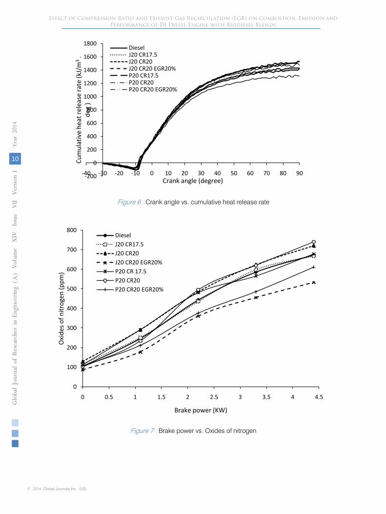
Figure 7 :
Brake power vs. Oxides of nitrogen
© 2014 Global Journals Inc. (US)
Globa
l Jo
urna
l of
Resea
rche
s in E
nginee
ring
(
)A
Vol
10
Year
2014
ume
XIV
I ssu
e V
II
Version
I
Effect of Compression Ratio and Exhaust Gas Recirculation (EGR) on Combustion, Emission and Performance of DI Diesel Engine with Biodiesel Blends
Figure 6 : Crank angle vs. cumulative heat release rate
-200
0
200
400
600
800
1000
1200
1400
1600
1800
-40 -30 -20 -10 0 10 20 30 40 50 60 70 80 90
Cu
mu
lati
ve h
eat
rele
ase
rate
(kJ
/m3
. d
eg )
Crank angle (degree)
DieselJ20 CR17.5J20 CR20J20 CR20 EGR20%P20 CR17.5P20 CR20P20 CR20 EGR20%
0
100
200
300
400
500
600
700
800
0 0.5 1 1.5 2 2.5 3 3.5 4 4.5
Oxi
des
of
nit
roge
n (
pp
m)
Brake power (KW)
Diesel
J20 CR17.5
J20 CR20
J20 CR20 EGR20%
P20 CR 17.5
P20 CR20
P20 CR20 EGR20%

Figure 9 :
Brake power vs. HC emission (ppm)
© 2014 Global Journals Inc. (US)
Globa
l Jo
urna
l of
Resea
rche
s in E
nginee
ring
()
AVol
11
Year
2014
ume
XIV
Issu
e V
II
Version
I
Effect of Compression Ratio and Exhaust Gas Recirculation (EGR) on Combustion, Emission and Performance of DI Diesel Engine with Biodiesel Blends
Figure 8 : Brake power vs. Smoke (FSN) 26
0
0.5
1
1.5
2
2.5
3
3.5
4
4.5
0 0.5 1 1.5 2 2.5 3 3.5 4 4.5
Smo
ke (F
SN)
Brake power (KW)
DieselJ20 CR17.5J20 CR20J20 CR20 EGR20%P20 CR 17.5P20 CR20P20 CR20 EGR20%
0
5
10
15
20
25
30
35
40
0 1 2 3 4 5
HC
em
issi
on
(pp
m)
Brake power (KW)
DieselJ20 CR17.5J20 CR20J20 CR20 EGR20P20 CR 17.5P20 CR20P20 CR20 EGR20

© 2014 Global Journals Inc. (US)
Globa
l Jo
urna
l of
Resea
rche
s in E
nginee
ring
(
)A
Vol
12
Year
2014
ume
XIV
I ssu
e V
II
Version
I
Effect of Compression Ratio and Exhaust Gas Recirculation (EGR) on Combustion, Emission and Performance of DI Diesel Engine with Biodiesel Blends
Figure 10 : Brake power vs. Carbon monoxide emission
Figure 11 : Brake power vs. carbon dioxide emission
0
0.02
0.04
0.06
0.08
0.1
0.12
0.14
0.16
0.18
0 1 2 3 4 5
Car
bo
n m
on
oxi
de
em
issi
on
(%
)
Brake power (KW)
Diesel
J20 CR17.5
J20 CR20
J20 CR20 EGR20
P20 CR 17.5
P20 CR20
P20 CR20 EGR20
0
1
2
3
4
5
6
7
8
9
10
0 1 2 3 4 5
Car
bo
n d
ioxi
de
emis
sio
n (
%)
Brake power (KW)
Diesel
J20 CR17.5
J20 CR20
J20 CR20 EGR20%
P20 CR 17.5
P20 CR20
P20 CR20 EGR20%

© 2014 Global Journals Inc. (US)
Globa
l Jo
urna
l of
Resea
rche
s in E
nginee
ring
()
AVol
13
Year
2014
ume
XIV
Issu
e V
II
Version
I
Effect of Compression Ratio and Exhaust Gas Recirculation (EGR) on Combustion, Emission and Performance of DI Diesel Engine with Biodiesel Blends
Figure 12 : Brake power vs. brake thermal efficiency 28
Figure 13 : Brake power vs. Exhaust gas temperature
0
5
10
15
20
25
30
35
0 1 2 3 4 5
Bra
ke t
her
mal
eff
cien
cy (
%)
Brake power (KW)
DieselJ20 CR17.5J20 CR20J20 CR20 EGR20%P20 CR 17.5P20 CR20P20 CR20 EGR20%
0
100
200
300
400
500
600
0 1 2 3 4 5
Exh
asu
t ga
s te
mp
erat
ure
(°C
)
Brake power (KW)
DieselJ20 CR17.5J20 CR20J20 CR20 EGR20%P20 CR 17.5P20 CR20P20 CR20 EGR20%

© 2014 Global Journals Inc. (US)
Globa
l Jo
urna
l of
Resea
rche
s in E
nginee
ring
(
)A
Vol
14
Year
2014
ume
XIV
I ssu
e V
II
Version
I
Effect of Compression Ratio and Exhaust Gas Recirculation (EGR) on Combustion, Emission and Performance of DI Diesel Engine with Biodiesel Blends
Table 2 : Technical specifications Diesel engine
Table 3 : Analysis of biodiesel test matrix for study on DI diesel engine
Table 1 : Properties of Diesel, JME and PME blends
S.No Fuel blend Density (kg/m3)
Calorific value (kJ/kg)
Kinematic viscosity at 400C (cSt)
Flash point (0C)
Cetane number
1 Diesel 840 43000 3.90 50 482 JME 10 868 37956 5.17 162 52.703 JME 20 870 38450 5.43 169 53.014 JME 30 874 39423 5.62 171 53.45 PME 10 882 35412 5.21 160 46.176 PME 20 897 36010 5.64 163 46.487 PME 30 891 37675 5.97 166 46.80IS for Biodiesel(IS15607:2005)
860-900 - 2.5-6.0 120 min 46 min
Particulars Specifications
Manufacture& model Kirloskar-TAF1Fuel injection type Direct injectionNumber of cylinder 1Bore × stroke (mm) 87.5× 110Displacement volume (cc) 661.45Compression ratio 17.5:1Cooling system Air -cooledFuel Injection time 23.4 degree bTDCInjector opening pressure (bar) 200Loading type Eddy current dynamo meterRated speed (rpm) 1500Maximum power (kW) 4.4Maximum torque (Nm) 28
Variables Fuels used Details of fuel studied
Maintaining constant speed and varying loads 0%, 25%, 50%, 75% & Full load. Compression ratio 17.5, 19& 20EGR- 10%, 20% &30%.
Diesel- Baseline fuelJme- Diesel blends (10, 20 & 30% Jme)PME- Diesel blends (10, 20 & 30% Pme)
Evaluation of combustion, emission and performance characteristics of the diesel engine with diesel and biodiesel blends.
optimum values
Maintaining constant speed and varying loads 0%, 25%, 50%, 75% &Full load. Compressionratio 20.EGR-20%.
Diesel-baseline fuelOptimum JME20-Diesel blend.Optimum PME20-Diesel blend.
study on combustion, emission and performance characteristics of the diesel engine with optimum blends, compression ratio and Exhaust gas recirculation

Table 6
: Performance and emission output values at full load
© 2014 Global Journals Inc. (US)
Globa
l Jo
urna
l of
Resea
rche
s in E
nginee
ring
()
AVol
15
Year
2014
ume
XIV
Issu
e V
II
Version
I
Effect of Compression Ratio and Exhaust Gas Recirculation (EGR) on Combustion, Emission and Performance of DI Diesel Engine with Biodiesel Blends
Table 4 : Lists of instruments details
Table 5 : Combustion parameters of Diesel, JME and PME fuels on diesel engine at full load condition
Instrument Measurement Range Accuracy Percentage of uncertainties
AVL GH14D Pressure Transducer Cylinder pressure
0-110 bar ±1 bar 0.20
AVL 365C angle encoder Crank angle -- ±1 2AVL3066A02 Piezo Charge Amplifier
Combustion pressure
0-700 bar ±0.01% 0.15
AVL 415 Smoke meter Smoke opacity 0-10 FSN ±0.1 0.9MRU delta 1600L Exhaust Gas Analyzer
NO 0-5000 ppm ±50 ppm 1.74UBHC 0-10000
ppm±10 ppm 0.31
CO 0-15 %vol ±0.06% 0.67CO2 0-20 %vol ±0.5% 0.4
K type Thermocouple EGT 0-1500°C ±1°C 0.4Burette Fuel
consumption1-30 cc ±0.1cc 0.15
Load cell Load 250-600 W ±1 W 0.21
Fuel Start of injection(°) bTDC
Start of combustion (°) bTDC
Ignition delay
Peak pressure (bar)
Peak heat releaserate (kJ/m3.deg)
Diesel 23.4 9.22 14.18 75.729 69.65.326J20 CR17.5 23.4 10.3 13.1 75.194 65.326J20 CR20 23.4 10.78 12.62 77.987 62.481J20 CR20 EGR20 23.4 12.16 11.24 76.501 64.427P20 CR17.5 23.4 9.78 13.62 75.253 79.791P20 CR20 23.4 10.48 12.92 75.201 76.478P20 CR20 EGR20 23.4 11.89 11.59 74.511 70.079
Parameters Diesel J20 CR17.5
J20 CR20
J20 CR20 EGR20
P20 CR17.5
P20 CR20
P20 CR20 EGR20
NOx (ppm) 673 668 721 534 678 741 612HC (ppm) 30 24.59 21.77 32.34 28.17 25.2 36.7CO (%) 0.154 0.139 0.121 0.163 0.1 0.147 0.124CO2 (%) 8.7 8.7 8.7 9 8.6 8.8 9.2Smoke (FSN) 3.61 2.24 3.31 3.496 2.8 2.62 4.24EGT (°C) 456 451 464 430 470 477 435BTE (%) 28.81 28.9 31.7 30.89 27 30 29.37

This page is intentionally left blank
Effect of Compression Ratio and Exhaust Gas Recirculation (EGR) on Combustion, Emission and Performance of DI Diesel Engine with Biodiesel Blends
© 2014 Global Journals Inc. (US)
Globa
l Jo
urna
l of
Resea
rche
s in E
nginee
ring
(
)A
Vol
16
Year
2014
ume
XIV
I ssu
e V
II
Version
I