effect of groundwater on open pit slope stability … › astudio1 › wp-content › ... · open...
TRANSCRIPT
EFFECT OF
GROUNDWATER ON
OPEN PIT SLOPE
STABILITY USING
ROCSCIENCE PHASE 2
2017
1
Abstract
Mining and construction activities have increased significantly over the period of time and
impact the environment to a great extent. While carrying out these activities it has become very
essential for the people working on it to effectively analyze subsurface conditions, ground
behavior and impact of applied loads to ensure less impact on the natural resources and limit
the impact on the environment and humans. Due to mining and construction activities the
excavation and landfills are carried out, which can weaken slopes and lands due to
displacement of materials within. Slope stability analysis is hence very important in
geotechnical field as slope instability can lead to damages to environment and humans. The
understanding of geology, soil properties and hydrology is essential in carrying out slope
stability analysis. In this research slope stability analysis is carried out to analyze the impact of
different materials and ground water on stability of slope. The research uses simulation
software wherein the samples collected are considered and tested to obtain geotechnical
parameter and factor of safety is calculated for a slope. The research uses Finite Element
Method (FEM) approach to predict behavior of the pit slope and evaluate stability of open pit
slope. The displacement and factor of safety has been studied using FEM. The method is found
to provide accurate results and it is recommended that software should be used to understand
slope stability better and should be continuously monitored to identify the slope stability failure
in the earlier stages itself and take necessary precautions and actions to avoid slope failure.
2
Table of Contents
1 Introduction .................................................................................................................................... 4
1.1 Introduction ............................................................................................................................ 4
1.2 Purpose of the Study ............................................................................................................... 5
1.3 Objectives of the study ........................................................................................................... 5
1.4 Research Questions ................................................................................................................ 6
1.5 Limitation ................................................................................................................................ 6
2 Literature Review ............................................................................................................................ 7
2.1 Factors impacting Slope Stability ............................................................................................ 8
2.1.1 Slope Geometry .............................................................................................................. 8
2.1.2 Geological structure ........................................................................................................ 8
2.1.3 Ground water .................................................................................................................. 9
2.1.4 Lithology .......................................................................................................................... 9
2.1.5 Dynamic Forces ............................................................................................................... 9
2.1.6 Cohesiveness ................................................................................................................. 10
2.2 Methods of Slope Stability Analysis ...................................................................................... 10
2.2.1 Limit Equilibrium Methods ............................................................................................ 10
2.2.2 Finite Element Methods ................................................................................................ 12
2.2.3 Shear Strength Reduction (SSR) Technique .................................................................. 13
2.3 Rocscience Software for Slope Stability ................................................................................ 14
3 Methodology ................................................................................................................................. 15
4 Modelling Simulation for this Research ........................................................................................ 17
4.1 Meshing ................................................................................................................................. 18
4.2 Materials Assigned ................................................................................................................ 19
4.3 Computation ......................................................................................................................... 22
4.4 Interpretation........................................................................................................................ 22
5 Conclusion ..................................................................................................................................... 29
6 Recommendations ........................................................................................................................ 30
7 References .................................................................................................................................... 31
8 Appendix: Phase2 Analysis Information: Project1 ........................................................................ 34
3
Table of Figures
Figure 1: Mesh Set-up for Open Pit Slope ............................................................................................. 18
Figure 2: Assigning Werribee Formation properties to slope ............................................................... 19
Figure 3: Assigning MBC Formation properties to slope ...................................................................... 20
Figure 4: Assigning Fyansford Formation properties to slope .............................................................. 20
Figure 5: Cross Section of Slope with Assigned Materials .................................................................... 21
Figure 6: Critical SRF 1 ........................................................................................................................... 23
Figure 7: Shear Strength Reduction 1 ................................................................................................... 23
Figure 8: Soil Profile 1 ........................................................................................................................... 24
Figure 9: Critical SRF 2 ........................................................................................................................... 24
Figure 10: Shear Strength Reduction 2 ................................................................................................. 25
Figure 11: Soil Profile 2 ......................................................................................................................... 25
Figure 12: Critical SRF 3 ......................................................................................................................... 26
Figure 13: Shear Strength Reduction 3 ................................................................................................. 26
Figure 14: Soil Profile 3 ......................................................................................................................... 26
Figure 15: Critical SRF 4 ......................................................................................................................... 27
Figure 16: Shear Strength Reduction 4 ................................................................................................. 27
Figure 17: Soil Profile 4 ......................................................................................................................... 28
Table of Tables
Table 1: Geotechnical Parameters ........................................................................................................ 21
Table 2: Parameters for Stability Assessment ...................................................................................... 21

4
1 Introduction
1.1 Introduction
Many of the industrial activities are leading to severe negative impact on the environment.
Open pit mining, which is one of the main and popular approach for mining activities in the
industry. These human induced slopes created for different functions has led to several
geotechnical problems. Open pit mining involves excavation of earth surface to obtain the
minerals under the earth for economic purpose (Fell et al., 2014). The process involves cutting
slopes and stability of pit slopes is very critical for safe mining operations. Analysis of stability
of operating slopes and the pit slope design is very important as slope failures can cause
production loss, additional investment for recovery and handling of other damages caused on
the site (Zhang, 2015). According to the researchers, slope instability is caused due to sliding
of mass of soil or sliding body in straight or curved sliding surface (Abramson et al., 2002).
Due to the stress on top of the earth and poor soil strength it can lead to cracks in the slop
making it unstable (Duncan et al., 2014). Due to increasing engineering projects, which
involve cut and fill slopes there is increased need to study and understand the causes of slop
instability and analyze slope stability and stabilization methods to reduce instability in slopes
and ensure effective design and construction of landfills, dams, excavations and other
constructions (Cheng & Lau, 2014). There are different factors, which influence the stability
of slopes and need effective understanding of geology, hydrology and soil properties (Duncan
et al., 2014). This research aims at analyzing slope stability using finite element method and
the safety factor for slopes is identified when it is influenced by groundwater levels.

5
1.2 Purpose of the Study
Slope stability analysis has become very critical to ensure the effective construction and
management of landfills and excavation (Abramson et al., 2002). Slope failure can lead to
damage of property and can cause accidents directly impacting human life (Fell et al., 2014).
As there are various factors, which influence stability of slop there are many uncertainties in
analysis of the slope stability and the accuracy of the analysis varies from one approach to other
and one site to the other (Cheng & Lau, 2014). The uncertainties include site topography,
variability of site, engineering properties, groundwater level, the characteristics of subsurface
materials and behavior of soil and rock. Shear strength parameters are considered to be
important in calculating the resistance of slope failure (Fell et al., 2014). The parameters are
random variables and distribution of them across slope varies with site. There is a need to
calculate factor of safety with greater accuracy before utilizing the slop for any activity. There
are different approaches to calculate factor of safety and have their own strength and
weaknesses. The limit equilibrium analysis has limitation of not considering stress and shear
strength and does not consider the ground behavior and assumes that safety factors are constant
along the slope failure surface. The finite element method enables better analysis of slop
stability but the influence of different factors does not ensure the accuracy. This research aims
at analyzing the accuracy of finite element analysis, which uses Shear Strength Reduction
(SSR) method to calculate safety facto and provide increased accuracy in slope stability
analysis.
1.3 Objectives of the study
To assess and understand the slope stability required to be carried out before any
construction work
6
To assess the slope failure possibility in natural or human made slope
To understand the impact of environmental factors on slope stability
To analyze the impact of seismic loadings on slopes
To identify preventive and remedial measures for overcoming slope failure and
maintaining slope stability
1.4 Research Questions
What is the significance of slope stability analysis?
How is the slope stability analysis carried out?
What influence des environmental factors have on slope stability?
What is the impact of seismic loadings on slopes?
What are the preventive and remedial measures to address slope failure issue and
maintenance of slope stability?
1.5 Limitation
This research uses developing computational algorithms based on the theoretical knowledge.
The simulation software can have certain limitation such as truncation errors and can cause
instability in the solution process. The assumptions made during the development of algorithm
can impact the accuracy of final outcome. The research uses a simulation software and hence
some factors have been assumed, which can lead to different results or affect the accuracy of
the final result. The results from the simulation is limited to impact of some specific materials
on the soil and slope stability.
7
2 Literature Review
Slope stability is one of the important areas in geo technical engineering, which is being studied
closely as the vulnerability of land to slope failure can increase due to inappropriate leading to
increased risk to people, property and infrastructure (Duncan et al., 2014). Slopes exist
naturally or are created by humans. Slope stability accidents are considered to be the leading
causes of fatalities in many parts of the world occurred during surface mining operations
(Cheng & Lau, 2014). Slope be it natural or human created lead to various geotechnical
problem. It is essential to understand the complexity of mechanical behavior of soil and the
load on the ground to understand the stability of slope (Duncan et al., 2014). The instability of
slopes in most cases can be visible in terms of sliding mass of soil, sliding body in straight or
curved sliding surface (Fell et al., 2014). Slopes become unstable due to stress on the top and
negligible soil strength mainly when the soil is fine-grained (Abramson et al., 2002). This can
lead to cracks in the slope and it is a sign of instability of slope occurring at early stage. Slope
stability analysis thus, becomes very essential to ensure safety and reliability of the slope and
if it is not stable possible remedial measures can be designed to stabilize the slop and avoid
occurrence of any major accident (Lee, 2016).
Slope stability problem is one of the greatest problems faced by open pit mining industry. In
open pit mining, the mineral deposits are obtained from ground surface and downward due to
which pit slopes are formed as the ore is being extracted from the ground (Fell et al., 2014).
The pit slopes have to be inclined at some angle to prevent failure of rock mass. Slope stability
problem can be categorized in to two, gross stability problem and local stability problem
(Ortigao, 2004). Gross stability problem occurs when large volumes of materials come down
the slope as a result of large rotational type of shear failure and has deeply weathered soil and
rock (Zheng et al., 2005). The local stability problem refers to problem wherein smaller volume
8
of material affects the slope and the failure effects only one or two benches in one time due to
shear plane jointing and slope erosion as a result of surface drainage.
2.1 Factors impacting Slope Stability
To understand the different scales and type of slope instability, the factors affecting them has
to be understood using the slope stability analysis techniques.
2.1.1 Slope Geometry
Geometrical slope design includes parameters such as height, area of failure surface and overall
slope angle (Fell et al., 2014). The slope stability decreases with increasing height. The overall
slope angle of 45 degrees is considered to be safe (Fell et al., 2014). Slope’s curvature has
increased impact on instability and slope sections, which are convex are recommended to be
avoided in slope design (Abramson et al., 2002). The stability keeps reducing with the
increasing steepness and height of the slope.
2.1.2 Geological structure
Some of the key structures, which affect slope stability in open pit mines include, direction and
amount of dip, joints and discontinuities, faults, which can act as conduits for ground water,
provide probable plane of failure and intra-formational shear zones (Cheng & Lau, 2014).
Slope instability can occur if starta dips into excavations as steepening of starta is critical for
stability of slopes (Duncan et al., 2014). Bedding planes and joints weaken the surfaces. Slope
stability depends on shear strength that is present along such surfaces and their orientation with
respect to slope and water pressure action on surface (Fell et al., 2014).
9
2.1.3 Ground water
Ground water can have adverse impact on the slope stability as it causes more up thrust and
drive water forces upwards. Ground water alters cohesion and frictional parameters and reduces
normal effective stress (Duncan et al., 2014). The chemical and physical effect of the pure
water pressure on the joint filling material can alter cohesion and friction of discontinuity
surface reducing the frictional resistances (Fell et al., 2014). This reduces shear resistance along
the plane by reducing normal stress acting on it. The water pressure in pores of rock cause
decrease in comprehensive strengths of the slope as confining stress gets reduced (Ge et al.,
2009)
2.1.4 Lithology
The rock mass strengths are determined by rock materials forming a pit slope and is affected
by faulting, discontinuities previous works, folding and weathering (Duncan et al., 2014). The
reduced rock mass strength is identified by circular, raveling and rock fall instability like
formation of slope (Abramson et al., 2002). The pit slopes, which have weathered or alluvium
rocks at surfaces have reduced shear strength, which reduces further if water seepage occurs.
2.1.5 Dynamic Forces
The blasting and vibration in open pit mining leads to increased shear stresses, which results
in dynamic acceleration of materials and creates stability problem in the slope surface. The
forces lead to ground motion and fracturing of rocks (Ge et al., 2009). According to Sage
(1976), poorly designed blasting can impact bench stability and can also cause rock mass
failure (Abramson et al., 2002). The blast damage causes back break, which reduces bench face
10
angle and hence for blasting of small scale slopes it is recommended that smooth blasting
approach is used (Ortigao, 2004). The impact of blasting is less on large scale slopes as the
back break and blast damage of benches have lesser impact.
2.1.6 Cohesiveness
The properties of rock or soil influence its resistance from being deformed or broken by forces
such as gravity (Ge et al., 2009). The actual cohesion between soil and cohesion is caused due
to electrostatic forces in the clays and cementing by NaCl, FE2O3 and other chemical and root
cohesion (Duncan et al., 2014). Slopes, which have less cohesion between rock and soil tend
to have lesser stability. The factors, which strengthen the cohesive force include friction,
cementation of grains due to silica deposition, stickiness of particles as it helps soil grains to
stick together, man-made reinforcements can help in preventing some material movement
(Cheng & Lau, 2014). The factors, which weaken the cohesive strength include high water
content, which weakens cohesion and adds weight to the mass, undercuts the slopes, vibrations
from earthquakes, blasting can create vibrations and alternating expansion by wetting and
contraction also reduces the strength of cohesion (Ge et al., 2009).
2.2 Methods of Slope Stability Analysis
2.2.1 Limit Equilibrium Methods
Limit equilibrium method is still widely used method for slope stability analysis. These
methods are widely used due to its simplicity and need of fewer parameters, which are
topography, slope geometry, static and dynamic loads, geology, hydrogeologic conditions and
geotechnical parameters (Cheng et al., 2007). These methods however, do not consider ground
11
behavior and safety factors are assumed to be constant along failure surface. In these methods
slopes are cut into fine slices so that their base can be compared with a straight line and then
form the equilibrium equations (Cheng & Lau, 2014). The differences in the value of safety
factor derived in different methods are mostly lower than 6% (Guyer, 2013). Some of the main
limit equilibrium methods are ordinary method of slices, Bishop’s modified method, Janbu’s
generalized procedure of slices, Morgenstern and Price’s method and Spencer’s method
(Ortigao, 2004). The ordinary method of slices is mainly used when slip surface is circular and
the moment equilibrium is around center of circle (Guyer, 2013). This method is applicable to
slopes, which are non-homogeneous and soils where slip surface can be approximated to a
circular form (Cheng et al., 2007). Using this method hand calculations can be done and is not
effective or accurate for effective stress analysis when high pore water pressures exist. Bishop’s
modified method is effective for slop surface, which are circular and equilibrium conditions
are satisfied by vertical equilibrium and overall moment equilibrium (Cheng & Lau, 2014).
This method has similar application as ordinary method of slices but it provides more accuracy
than the ordinary method of slices mainly while analyzing high pore water pressures. Even in
this method calculations can be done by hand and also using spreadsheet.
The Janbu’s Generalized procedure of slices can be used for slope having any slip surface and
satisfies the condition of force equilibrium (Cheng et al., 2007). This method is applicable for
non-circular slip surfaces and for shallow, long planar surfaces, which fail and are not parallel
to the ground surface. The other limit equilibrium method includes Morgenstern & Price’s
method, which can be used for any shape of slip surface and satisfies all conditions of
equilibrium (Cheng & Lau, 2014). This method is one of the accurate procedure and is
applicable to all slope geometrics as well as soil profiles virtually. It is a well establishes and
rigorous equilibrium procedure (Zhang, 2015). The Spencer’s method can also be used for any
shape slip surface and is also an accurate procedure and can be applied to all soil profiles and
12
slop geometrics. It is the simplest equilibrium procedure for calculating factor of safety (Huang,
2014).
2.2.2 Finite Element Methods
The different limit equilibrium methods are developed on arbitrary choice of a series of slip
surfaces and defining them in a manner that they give minimal value of safety factor (Guyer,
2013). But in recent times the intensive use of numerical analysis methods have given access
to constraints and deformations within formations that constitute sub-soil (Zheng et al., 2005).
It is hence essential to know behavior law of the considered formation and volume of ground
has to be divided in to geometric elements, which are subjected to action of close elements
(Hammouri et al., 2008). The calculations in this method involves determining displacements
and stress fields, which are compatible with behavior law, mechanic equations and adopted
behavior law (Stacey et al., 2003). The finite element method enables calculation of stresses
and deformation state in rock mass with respect to its self weight with assumption of behavior
law adopted. The finite element method analyzes the slope stability by considering the static
permission, relationship between stress and strain and does not consider irregular slope
geometry shape and limitation of material inhomogeneity (Zheng et al., 2005). The finite
element method provides various advantages as compared to traditional limit equilibrium
method. In finite element, there is no need for assumptions to be made in advance about
location of failure of the shape of slope (Hammouri et al., 2008). This method considers that
failure can occur naturally due to the different zones within soil mass and where soil shear
strength is not able to sustain applied shear stresses (Zheng et al., 2005). The other advantage
of this method it does not have to consider the concept of slice and no assumptions about the
slice side forces have to be made. This method maintains global equilibrium till failure is
reached (Huang, 2014). This method enables considering realistic soil compressibility data and
solutions provide information about deformations at working stress levels (Stacey et al., 2003).
13
The finite element method has the ability to monitor progressive failure up to overall shear
failure including the shear failure.
2.2.3 Shear Strength Reduction (SSR) Technique
The raid development in computer technology and constant development of the approaches of
calculating slope stability promoted the use of finite election method in the geotechnical
practice (Huang, 2014). The finite element method is very effective in ca practically consider
all kinds of geometry, model key aspects of different behavior of the materials such as stress
paths and combined stress-pore pressure variations (Stacey et al., 2003). Shear Strength
Reduction (SSR) technique helps in finding slope factor of safety. The factor of slope safety
can be referred to as ratio of actual shear strength of the soil to minimum shear strength required
to prevent failure or it can be considered as factor by which soil shear strength must be reduced
to bring slope to verge of failure (Hammouri et al., 2008). In the SSR technique elasto-plastic
strength is assumed for all materials and material shear strengths are reduced progressively till
it collapses (Zhang, 2015). This approach provides various advantages over traditional limit
equilibrium technique wherein it eliminates need for prior assumptions of failure mechanisms
such as type, shape and location of surface failures (Stacey et al., 2003). The SSR finite element
technique automatically implements critical failure mechanism and eliminates artificial
separation of slope issues into the slip surface failures and those involving failure of deformed
wedges (Huang, 2014). The SSR technique minimizes expertise essential in finding critical
failure mechanisms for some specific slope problems. In some situations, these can go
unnoticed by the slope engineers.
To calculate the slope stability effectively using SSR technique it is essential to choose a proper
constitutive model for stability analysis and among several commonly used linear and non-
14
linear constitutive models, elastic-perfectly plastic model with Mohr-Coulomb failure criterion
is widely adopted (Cheng et al., 2007). This model is effective as the sudden transition of soil
behavior from elastic to plastic state in elastic-perfectly model helps in identifying factor of
safety while applying strength-reduction technique. The steps involved for Mohr-Coulomb
materials for systematic searching for critical factor of safety value that brings a previously
stable slope to verge of failure are to develop a finite element model of slope considering
deformation and strength properties for the slope materials. The model should then be
computed and maximum total deformation in slope has to be recorded. In the next step, the
value of factor of safety F should be increased and the factored Mohr-Coulomb material
parameters should be calculated. The new strength properties should be entered into the slope
model and has to be computed again. The maximum total deformation should be recorded. The
process then should involve repeating the second step of increasing factor of safety and
computing again and recording maximum total deformation of slope till the model does not
converge to a solution, which includes the critical factor of safety value just beyond which
failure of slope occurs. The computation should be repeated by reducing material strength till
slope fails.
2.3 Rocscience Software for Slope Stability
Rocscience is one of the organizations, which offers geotechnical software that are used by
various customer segments (Rocscience, 2016). Slope stability analysis is one of the important
software at Rocscience and the program includes analyzing soil and rock stability using limit
equilibrium and finite element analysis and 2D and 3D modeling. Phase 2 is one of the powerful
software tool developed by Rocscience and uses 2D finite element programs for applications
in soil and rock stability analysis (Rocscience, 2016). Phase 2 software can be used for range
15
of engineering projects such as slope stability probabilistic analysis, groundwater seepage and
dynamic analysis capabilities. This software helps in carrying out slope stability analysis using
finite element approach’s sheer strength reduction method (Rocscience, 2016). It includes
steady-state, finite element groundwater seepage analysis options within the program. It also
has the option to determine pore pressure and flow and gradient based on user defined hydraulic
boundary conditions and conductivity of the material (Rocscience, 2016). The analysis is fully
automated and can be used with Mohr-Coulomb strength parameters. The slope models are
imported and exported between Slide and Phase 2 enabling the user to easily compare the
results form limit equilibrium and finite element methods (Rocscience, 2016). The software
provides the option of carrying out the analysis of complex slope models in a very short period.
3 Methodology
Research using scientific methods enable researcher to develop new theories or verify existing
hypothesis (Creswell, 2013). This research is an experimental research, which is mainly used
in sciences such as physics, chemistry, geotechnical, sociology and other areas. Experimental
research is collection of different research designs, which use controlled and manipulated
testing approaches to understand causal processes (Christensen et al., 2013). In this research
approach one or more variables are manipulated to determine their effect on the chosen
dependent variable (Creswell, 2013). Experimental method is a systematic approach to research
wherein the researcher manipulates certain variables and controls and measures any changes
in the other variables with respect to the manipulated variable (Bartz-Beielstein, 2006). In this
research approach, there is time priority as experimental research is based on causal
relationship in which causes precedes effect. The magnitude of correlation is excellent and

16
consistency in causal relationship is high (Robsinson, 2014). In this research method researcher
manipulates one variable and control/randomizes the rest of the variables.
There are many complex systems in physical sciences, which are studied by developing models
of the underlying physics on computer and by using computationally intensive methods to
understand and learn about the behavior of the systems or the response of the systems to certain
event. Such methods are called simulations (Christensen et al., 2013). The mathematical
models, which drive the simulations are based on theory. Computer simulations are techniques,
which study complex systems or phenomenon. Experiments to be carried out in laboratories on
computer uses theoretical model and the equations are transformed into computable algorithm,
which can be run on the computer and the dependent variables, which are derived from the
computation stimulate evolution of system being studied (Bartz-Beielstein, 2006). Some of the
simulators or software have sophisticated graphical techniques, which are often used to
transform output of the research into graphics and videos. By using simulations, the
experimental setups on computer can provide much wider variety of initial condition, which
can be studied and much more detailed can be obtained (Robsinson, 2014). Modelling and
simulations are of increased value in scientific discovery as it provides additional insights about
the system being studied, which are often not practical and impossible to determine through
real-world experimental and theoretical analysis (Christensen et al., 2013).
Modelling and simulations enable researcher to mimic the real-world system and can be
experimented on by considering different conditions and hence this research approach provides
in-depth understanding of the system and impact of the external forces on the system
(Robsinson, 2014). The successful simulation studies not just compute numbers but also make
use of variety of techniques to draw various inferences from the numbers, which are computed
(Bartz-Beielstein, 2006). It makes use of calculation techniques that can be used to consider
complex mathematical and theoretical aspects. Simulations and laboratory experiments both
17
have to manage uncertainties, which is found to be negligible. A simulation software, which
has capacity to accurately mimic a complex phenomenon includes increased level of
information about the phenomenon and some of the variables such as temperature, pressure,
wind velocity and other are evaluated at thousands of points by the computer as it stimulates
the system (Walliman, 2010). Modelling and simulation is not carried out to verify proposed
theory but to observe and replace computation of theory, which has not been deeply studied or
has certain area, which has not been studied deeply in the real-context. Modelling and
simulations provide an effective means to understand the phenomenon or system more
effectively by considering different dependent variables and applying them at different levels
in the system (Robsinson, 2014).
4 Modelling Simulation for this Research
In modelling simulation process the open pit mine design will be drawn to find factor of safety
for the chosen area. The steps involved in the analysis of the slope stability using Phase 2
software are
1st Step: Specifying all the critical points number in the design chart.
2nd Step: Measuring each of the critical point and calculating their x-y coordinates
3rd step: Putting the coordinates of each lines’ critical points one by one in the Phase 2 software
to complete the cross section of open pit mine.
4th Step: Defining each plane with specified material
5th Step: Meshing the part of cross section of mine
6th Step: Entering the property parameters to different materials of work
18
7th Step: Starting the simulation
Rocscience Phase 2 software analysis report is provided in the Appendix.
4.1 Meshing
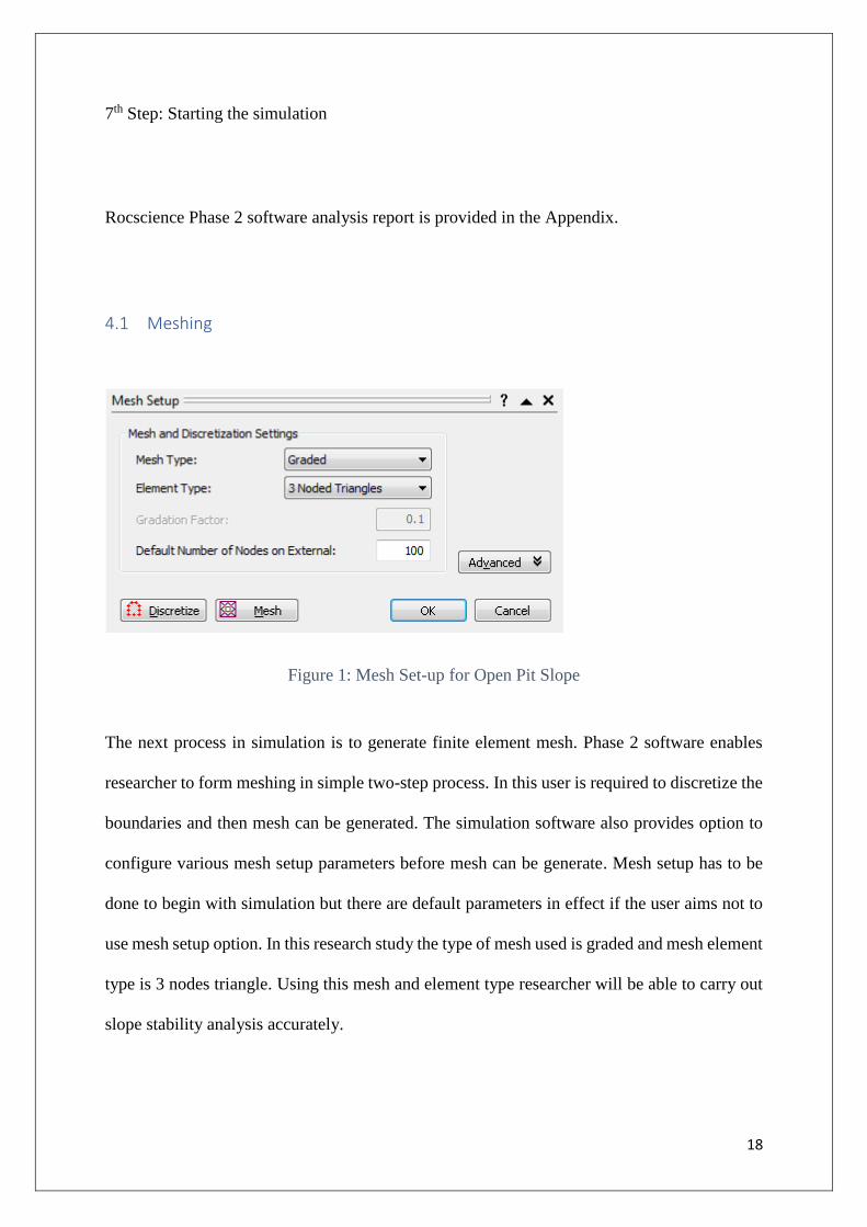
Figure 1: Mesh Set-up for Open Pit Slope
The next process in simulation is to generate finite element mesh. Phase 2 software enables
researcher to form meshing in simple two-step process. In this user is required to discretize the
boundaries and then mesh can be generated. The simulation software also provides option to
configure various mesh setup parameters before mesh can be generate. Mesh setup has to be
done to begin with simulation but there are default parameters in effect if the user aims not to
use mesh setup option. In this research study the type of mesh used is graded and mesh element
type is 3 nodes triangle. Using this mesh and element type researcher will be able to carry out
slope stability analysis accurately.

19
4.2 Materials Assigned
The chosen materials are then assigned to the cross section, which include weeribee formation,
MBC formation, fyansford formation, material 4 and material 5. As shown below the
simulation allows the user to select properties and define each property of different materials.
The below figures represent the choices made in the simulations of the different materials and
its application on the slope with details of its frictional angle and peak of the slope, which
would be considered to compute the slope stability and the impact of different materials on the
slope stability.
Figure 2: Assigning Werribee Formation properties to slope
20
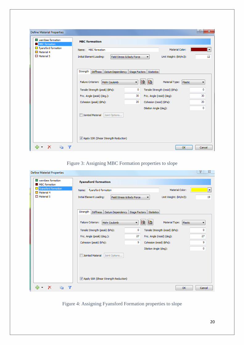
Figure 3: Assigning MBC Formation properties to slope
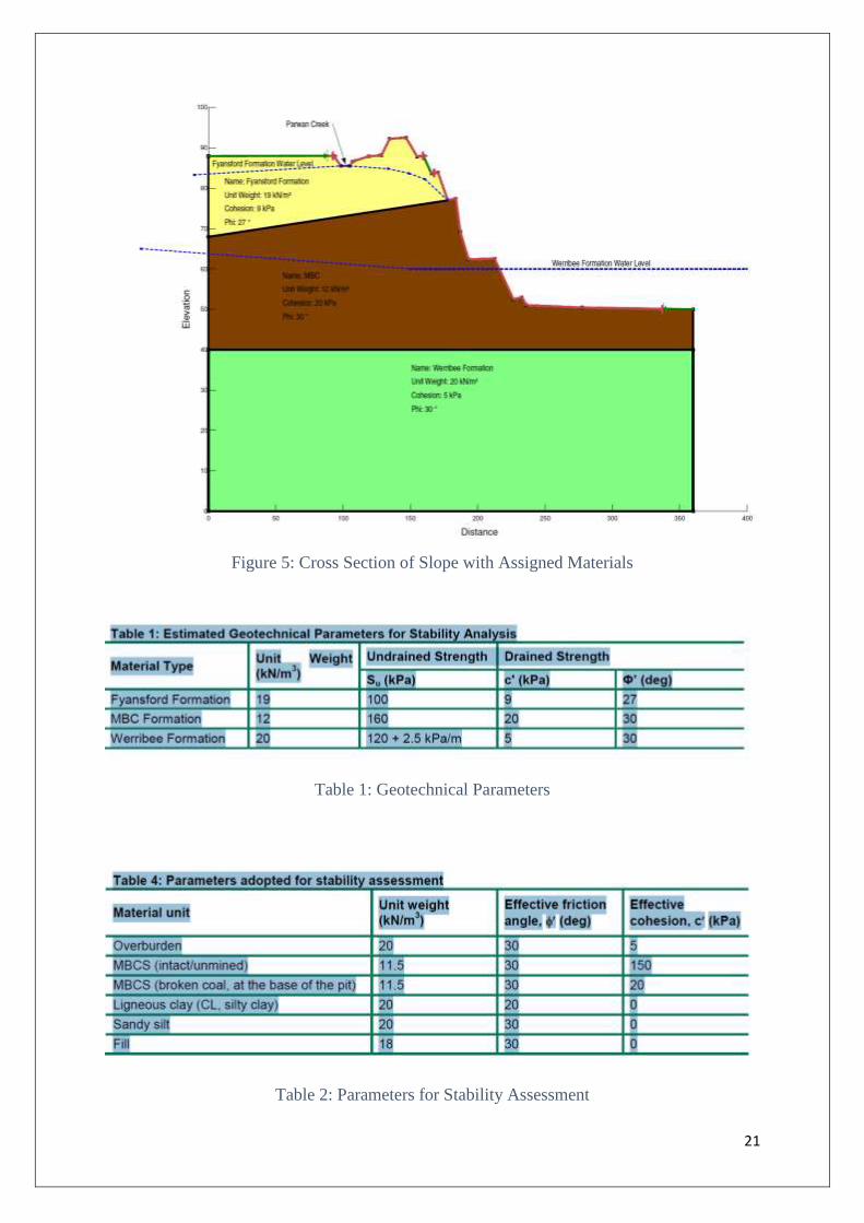
Figure 4: Assigning Fyansford Formation properties to slope
21
Figure 5: Cross Section of Slope with Assigned Materials
Table 1: Geotechnical Parameters
Table 2: Parameters for Stability Assessment
22
The above tables highlight the estimated geotechnical parameters considered for stability
analysis. And parameters adopted for stability assessment. The geotechnical parameters of the
materials considered in the slope include its weight, undrained and drained strength and the
angle of its force on the slope. The internal elements of the materials considered for slope
stability analysis included composition of different material units, which have different friction
angle and cohesiveness and influence the slope stability in different manner.
4.3 Computation
The above figure shows the choice of material, the color representation of the chosen material,
its unit weight, frictional angle and cohesion and the Shear Strength Reduction Factor is
applied. The SSR method, which is used in this research Mohr-Coulomb. The Apply SSR box
is checked as the research uses model with joints. SSR option in the Phase 2 software allows
researcher to automatically carry out finite element slope stability analysis and compute critical
strength reduction factor for the respective model. After SSR analysis is computed the results
will provide critical Strength Reduction Factor (SRF), which will automatically be displayed.
The maximum shear strain contours will be shown by default as it tends to highlight the critical
failure zone.
4.4 Interpretation
23
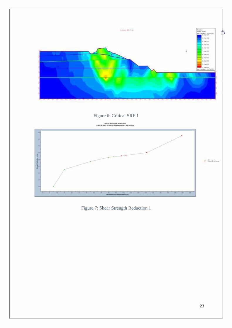
Figure 6: Critical SRF 1
Figure 7: Shear Strength Reduction 1
24
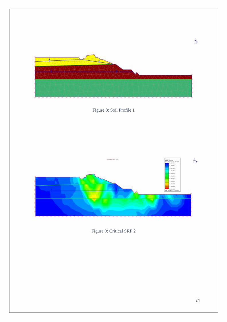
Figure 8: Soil Profile 1
Figure 9: Critical SRF 2
25
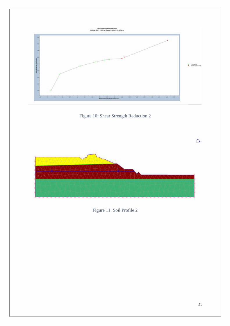
Figure 10: Shear Strength Reduction 2
Figure 11: Soil Profile 2
26
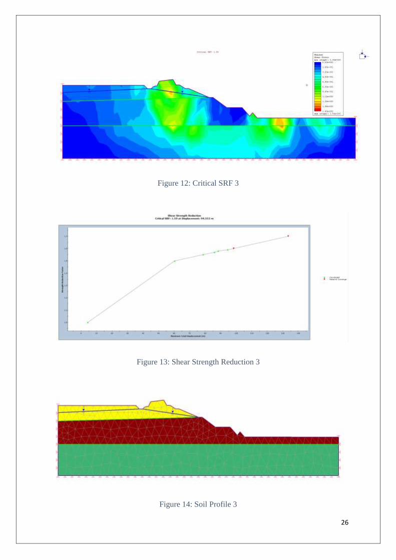
Figure 12: Critical SRF 3
Figure 13: Shear Strength Reduction 3
Figure 14: Soil Profile 3
27
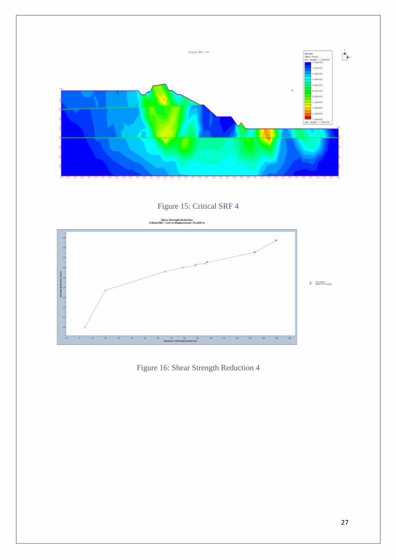
Figure 15: Critical SRF 4
Figure 16: Shear Strength Reduction 4

28
Figure 17: Soil Profile 4
After computing the SSR analysis the Strength Reduction Factor is automatically displayed
and the maximum shear contours is shown by default as it tends to highlight critical failure
zone. The above figures show the analysis using Finite Element Method, which provides the
strength reduction factor based on the stress applied at different points on the slope. The four
critical SRF’s obtained by measuring it at different points on the slope are 1.44, 1.47, 1.59 and
1.64. The graphs, which are plotted between SRF and maximum total displacement displays
the displacement of the materials on the slope with respect to critical SRF. The total
displacement when the critical SRF is 1.44 is 86.909m, at critical SRF the displacement is
82.636, at critical SRF of 1.50 the displacement is 94.553 and at critical SRF of 1.64 the
displacement is 95.668 m. The above Figure 7, Figure 9, Figure 11, Figure 13 represent soil
formation from the slope stability analysis of open pit cross section with 2 water tables, with
only 1st water table with only 2nd water table and with no water tables.
The graphs represent the results of SSR Analysis. Each data point highlights the Strength
Reduction Factor against Maximum Displacement for one iteration of SSR analysis. The
Maximum Displacement provides the maximum displacement value which occurred at each
point in the model during stress analysis, which was computed using the SRF value. The green
data point represents the point for which stress analysis results achieved convergence, which
29
means that the model is unstable at that point. The data points in red represent analysis for
which stress analysis has not achieve convergence within specified tolerance, which highlights
that the slope is still stable at that point in spite of the stress of different materials.
5 Conclusion
Slope stability analysis is considered important to ensure safety of the environment and
humans. There are different factors, which influence the slop stability, which include impact
of different materials, geological factors and human activities, which can deteriorate the
strength of the slope and lead to instability in the slope. There are different approaches to
analyze slope stability, which includes limit equilibrium and finite element method. Limit
equilibrium method has several limitations as the slope surface and some factors are assumed
as constant, which can lead to inaccurate outcomes. Finite element method on the other hand
provides many advantages such as no need of assumptions of location of failure in the slope,
considers relationship between stress and strain, does not consider irregular slope geometry
shape, analyzes failure of slope in any condition with or without soil mass. This research using
the modelling simulation method determines the factor of safety. The research uses the
Rocscience Phase 2 software and built-in functions for finite element method in the software
simulator for determining the factor of safety and failure surface applying strength reduction
method. The factor of safety for soil slope was obtained by finite element analysis and provided
an accurate analysis of the SRF and enabled effective slop failure investigations. The outcome
of the simulation showed that as the factor of safety increases the displacement increases and
also the displacement is influenced by the water presence in the soil but to a smaller extent.
The difference in material also has different impact on the shear strength reduction. The finite
element method should be used to determine the materials, which reduces the displacement of

30
the soil formation, which can then be used to analyze the potential of slope and also assess its
stability level.
6 Recommendations
Slope failure in an open pit mine is currently identified and avoided using conventional
techniques of using certain approach to reduce stress on the slope or applying strengths at
different angles, which consumers more time for carrying out the necessary tasks. There is loss
of time, production and money invested in such processes and the conventional system are
effective only when slope is nearing its failure. It is suggested that instead computer simulation
should be used to find exact location of slope failure at the beginning when tension cracks
begin to form and which can then later lead to slop failure. The sites can have automatic and
continuous slop monitoring system, which can regularly monitor the exact location of slope
failure in a mine and highlight the possible cracks and weaker areas in the slope, which will
enable the people working in the mine to take necessary actions to overcome the possible slope
failure or avoid causing further crack in the slope by changing their work activities and
procedures.

31
7 References
Abramson, L, Lee, T, Sharma, S, Boyce, G (2002), Slope stability and stabilization methods.
2nd ed., Canada: John Wiley & Sons, Inc.
Bartz-Beielstein, T (2006), Experimental Research in Evolutionary Computation: The New
Experimentalism, New York: Springer
Cheng, Y, Lansivaara, T, Wei, W (2007), Two-dimensional slope stability analysis by limit
equilibrium and strength reduction method. Computers and Geotechnics, Vol. 34, No. 3, pp.
137-150.
Cheng, Y & Lau, C (2014), Slope Stability Analysis and Stabilization,2nd ed., New York: CRC
Press
Christensen, L, Johnson, R & Turner, L (), Research Methods, Design, and Analysis, 12th ed.,
New York: Pearson
Creswell, J (2013), Research Design: Qualitative, Quantitative, and Mixed Methods
Approaches, 4th ed., New York: SAGE Publications Inc.
Duncan, M, Wright, S & Brandon, T (2014), Soil Strength and Slope Stability, 2nd ed., New
York: Wiley
Fell, R, MacGregor, P, Stapledon, D, Bell, G & Foster, M (2014), Geotechnical Engineering
of Dams, New York: CRC Press
32
Ge, L, Liu, J, Ni, J & He, Z (2009), Slope Stability, Retaining Walls, and Foundations,
American Society of Civil Engineers
Guyer, G (2013), An Introduction to Slope Stability Analysis, CreateSpace Independent
Publishing Platform
Hammouri, N, Malkawi, A & Yamin, M (2008), Stability analysis of slopes using the finite
element method and limiting equilibrium approach, Bulletin of Engineering Geology and the
Environment, Vol. 67, Iss. 471
Huang, Y (2014), Slope Stability Analysis by the Limit Equilibrium Method, American Society
of Civil Engineers
Lee, D (2016), The Second Rush: Mining and the Transformation of Australia, Connor Court
Publishing Pty Ltd
Ortigao, J (2004), Handbook of Slope Stabilization Engineering, New York: Springer
Robsinson, S (2014), Simulation: The Practice of Model Development and Use, San Francisco:
Palgrave
Rocscience (2016), viewed 7 May, 2017
https://www.rocscience.com/rocscience/products/rs2
Stacey, T, Xianbin, Y, Armstrong, R & Keyter, G (2003), New slope stability considerations
for deep open pit mines, The Journal of The South African Institute of Mining and Metallurgy,
Vol. July /August 2003, pp. 373-390
33
Walliman, N (2010), Research Methods: The Basics, Routledge
Zheng, H, Liu, D & Li, C (2005), Slope stability analysis based on elasto-plastic finite element
method, Int. J. Numer. Meth. Engng, Vol. 64, pp.1871–1888
Zhang, Y (2015), The Study Methods and the New Progresses of Slope Stability, 2nd
International Conference on Machinery, Materials Engineering, Chemical Engineering and
Biotechnology

34
8 Appendix: Phase2 Analysis Information: Project1