effect of reducing strains by sfrc pavement on ohira viaduct · effect of reducing strains by sfrc...
TRANSCRIPT

Effect of reducing strains by SFRC pavement on Ohira Viaduct
Takayoshi Kodama1, Mamoru kagata, Shigeo Higashi, Kiyoshi Itoh, Yatsuhiro Ichinose
Abstract
Fatigue damage of orthotropic steel bridge decks owing to increasing traffic volumes and higher wheel loads have been reported. Steel fiber reinforced concrete (SFRC) pavement holds promise as a countermeasure for improving the fatigue durability of existing orthotropic steel decks. Static loading tests using a 200 kN dump truck were conducted on the orthotropic steel deck of the Ohira Viaduct. This paper reports the results of strains measurement before and after construction of the SFRC pavement, which show a marked effect in terms of reducing local strains in the steel deck.
Introduction There have been numerous reports of fatigue-induced damage and cracking
concerning orthotropic steel deck bridges used by heavy vehicles. The reported crack occurrences were in the welds between transverse ribs and longitudinal ribs, the welds between longitudinal ribs and deck plates, the welds between neighboring longitudinal ribs, etc. Rare instances of cracks that originate in the vicinity of a deck plate and run through that deck plate, as well as road surface subsidence [1, 2], also have been reported, raising the possibility of traffic accidents and making this an important issue to be addressed.
A number of studies have been conducted on how to prevent such fatigue damage, including the use of highly rigid steel fiber reinforced concrete (hereafter, SFRC) for the pavement of the steel deck to inhibit local deformation of the steel deck, and the reduction of local stress to improve fatigue durability. SFRC pavement was used a long time ago by the Nagoya Expressway Public Corporation [3] as a way to prevent pavement damage of ramps with a steep longitudinal gradient, tollgates, etc. More recently, as a fatigue countermeasure for steel decks, SFRC pavement was applied through a new method using epoxy resin adhesive instead of conventional stud dowels for the joints between the SFRC and deck plate, in the section of National Highway 357 forming the lower level of Yokohama Bay Bridge [4, 5], Shonan-Ohashi Bridge [6, 7], and the Metropolitan Expressway [8].
The Ohira Viaduct, an orthotropic steel deck bridge currently in service in Oyama, Tochigi Prefecture, features SFRC pavement as part of various fatigue countermeasures. In the present study, we used this location to run truck-loading tests on old-type asphalt pavement and new-type SFRC pavement as shown in Fig.1 and Fig.2. These tests revealed the effectiveness of SFRC pavement in reducing stress on the steel deck, as reported below.
1 Manager, Technology Department, KAJIMA ROAD.,LTD

Influence of an overlay material
First of all, the result of researching the adhesion of an adhesive and fresh concrete is shown below. (1) Three type of overlay materials used for the experiment
It was compared with the adhesion from the difference of overlay materials (cement paste, mortar and concrete) to hardening base concrete. The used mixture proportions of base concrete are shown in Table 1. The used cement paste as overlay material was made into 47% that is the same water cement ratio as the concrete shown in Table1. The used cement mortar as overlay material was used as water cement ratio 0.47 of cement paste, and three kinds of sand-cement ratio such as 0.1,0.5, and 2.39 were added. Furthermore, overlay concrete that had sand-total aggregate ratio from 40% to 49% was also used. The examination was executed after 7days from producing the test cores. 0.7kg per 1square-meter of epoxy-adhesives were applied. The time interval from spraying the adhesives to overlaying the fresh concrete was made into 1 hour so that it might achieve the same conditions as real construction.
The test result of bonding strength by different overlay materials is shown in Fig.1.
The bonding strength of cement paste and the mortar of 0.1 and 0.5 is a small value, and they had exfoliated in the bonding interface. With the mortar of 2.39 and concrete, it had excellent bonding strength and the position of rupture was mostly inside the mortar or concrete. From the result of this bonding test, it is thought that existence of aggregate is indispensable in bonding with adhesives and fresh concrete. Aggregates bonded with adhesives first, paste up firmly, and it is thought that concrete hardens and unifies after that. Fig. 2 shows the bonding strength in the case of sand-total aggregate ratio in the range between 40% and 49%. In this range, bonding strength was almost the same. Therefore, it is thought that there is almost no influence that the rate of fine aggregate has to bonding strength. (2)Various intensity of the BONDED concrete by EPOXY ADHESIVE AGENT
Cementpaste
MortarS/C=0.1
MortarS/C=0.5
MortarS/C=2.39
Concrete0.0
0.5
1.0
1.5
2.0
2.5
3.0
Bonding strength (N/mm2)
0
1
2
3
4
37 40 43 46 49 52
Bondin
g st
rengt
h (
N/m
m2)
Sand percentage (%)Fig. 2 Relationship of sand
percentage and bonding
Table 1 Mixture proportions of concrete
Unit contents(kg/m3) Ad Cx%Gmax
(mm) W/C (%)
s/a(%)
W C S G 20 47.0 44.4 157 334 797 1030 0.7
Gmax means the maximum size of aggregates. Small size figure of s means the volume of sands and a means the volume of aggregates. Cx% means the content percentage of admixture to cements.
Fig. 1 Bonding strength of cement paste and mortar

Next, the strength property in the case of putting it with the adhesives is shown. The used mixture proportion of concrete is shown in Table 1.The cylinder specimen with diameter of 100mm and height of 200mm was used for the tests of compressive strength and shear strength. The height of base concrete and overlay concrete was 100mm in 200mm high. The speed of loading in shear test was controlled by displacement to be set to 1mm per 1 minute. The specimen used for the bending test was 100mm in height, 100mm in width, and 400mm in length, and the base concrete was set to the lower layer. 0.7kg per 1square-meter was sprayed on base concrete, and fresh concrete was placed 5 hours after the application. The examination was executed after 14 days from placing the concrete.
The results of strength test are shown in Fig.3. The bonding strength of bonded specimen was equivalent to a body of base concrete and overlay concrete. Moreover, there was no exfoliation at interface between base concrete and overlay concrete. Shear strength of bonded specimen is equivalent to base concrete and overlay concrete, and the rupture position is inside of the overlay concrete. It is thought that this was destroyed in concrete because interfacial bonding strengths of the adhesive and the overlay concrete are larger than tensile strength of overlay concrete. Sufficient adhesion to shear stress was checked. It was shown that it is equivalent to a body of base concrete and overlay concrete in compressive strength, and the adhesion by adhesives is absolutely excellent.
Fig. 3 Strengths of adhesive bonded specimen Outline of Ohira Viaduct and SFRC paving
The Ohira Viaduct is a road bridge on National Highway 50 consisting of 31 spans and measuring 987 m. The bridge's two inbound (Takasaki-bound) lanes were completed in 1983, and its two outbound lanes, which run parallel with the inbound lanes, were opened to traffic in 2005. The bridge has independent superstructures for the inbound lanes and outbound lanes, but common piers support these. The Ohira Viaduct was paved with SFRC over a length of 213 m, consisting of one 3-span continuous 2-box girder and two simple plate box girders of the steel deck with U-ribs of the inbound lanes. The part of the bridge that was selected for measurement in the present study consisted of a 3-span continuous steel deck 2-box girder spanning piers 3 to 6 of the inbound lanes (Takasaki-bound). The deck plates are 12 mm thick, the
0
1
2
3
4
5
6
Bending strength (N/mm2)
Existingconcretespecimen
Overlayconcretespecimen
Adhesiveconcretespecimen
0
1
2
3
4
5
6
7
Shear strength (N/mm2 )
Existingconcretespecimen
Overlayconcretespecimen
Adhesiveconcretespecimen
0
10
20
30
40
50
60
Compressive strength (N/mm2)
Existingconcretespecimen
Overlayconcretespecimen
Adhesiveconcretespecimen
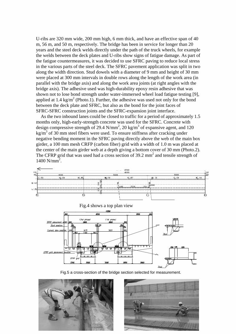
U-ribs are 320 mm wide, 200 mm high, 6 mm thick, and have an effective span of 40 m, 56 m, and 50 m, respectively. The bridge has been in service for longer than 20 years and the steel deck welds directly under the path of the truck wheels, for example the welds between the deck plates and U-ribs show signs of fatigue damage. As part of the fatigue countermeasures, it was decided to use SFRC paving to reduce local stress in the various parts of the steel deck. The SFRC pavement application was split in two along the width direction. Stud dowels with a diameter of 9 mm and height of 30 mm were placed at 300 mm intervals in double rows along the length of the work area (in parallel with the bridge axis) and along the work area joints (at right angles with the bridge axis). The adhesive used was high-durability epoxy resin adhesive that was shown not to lose bond strength under water-immersed wheel load fatigue testing [9], applied at 1.4 kg/m2 (Photo.1). Further, the adhesive was used not only for the bond between the deck plate and SFRC, but also as the bond for the joint faces of SFRC-SFRC construction joints and the SFRC-expansion joint interface.
As the two inbound lanes could be closed to traffic for a period of approximately 1.5 months only, high-early-strength concrete was used for the SFRC. Concrete with design compressive strength of 29.4 N/mm2, 20 kg/m3 of expansive agent, and 120 kg/m3 of 30 mm steel fibers were used. To ensure stiffness after cracking under negative bending moment in the SFRC paving directly above the web of the main box girder, a 100 mm mesh CRFP (carbon fiber) grid with a width of 1.0 m was placed at the center of the main girder web at a depth giving a bottom cover of 30 mm (Photo.2). The CFRP grid that was used had a cross section of 39.2 mm2 and tensile strength of 1400 N/mm2.
To Takasaki Bridge length
Gauge attachment
Gauge attachment
Fig.4 shows a top plan view
Fig.5 a cross-section of the bridge section selected for measurement.

Structural Considerations of SFRC
The main aspects considered are SFRC and the width of the CFRP grid were considered outlined below. Regarding the thickness of the SFRC, three cases were considered, namely the same thickness as the asphalt pavement (75 mm), greater thickness than the asphalt pavement (100 mm), and a two-layer pavement (SFRC thickness of 45 mm + surface asphalt thickness of 30 mm), conducting comparisons in terms of economic efficiency, workability, and maintainability. In the end, SFRC with the same thickness of 75 mm as the existing asphalt pavement was selected. Regarding the CRFP grids and stud dowels for reinforcing the SFRC, two models, the SFRC directly over main girder model and the one bridge portion model were examined using finite-element analysis. The degree of stress generated in SFRC varies according to the steel deck structure, including main girder placement, transverse rib interval, and U-rib interval, and the degree of stress generated by live load, heat of cement hydration, etc., was obtained with the bridge part model modeling the Ohira Viaduct.
The effectiveness of CFRP grids for limiting the crack width in SFRC was confirmed as a result, and 1.0 m above the main girder was selected as the installation range. With regard to warping of the pavement owing to heat of cement hydration, drying shrinkage, etc., adhesive was judged to be a sufficient countermeasure and the use of stud dowels was deemed unnecessary. However, as the long-term durability of adhesive in the actual bridge was not ascertained, it was decided to use stud dowels only at the edges of the SFRC to prevent the infiltration of water, etc., in case of peeling off of the adhesive layer. Further, with regard to the future maintenance and repair of the SFRC pavement, the height of the stud dowels was set to 30 mm (special-order product) and the bottom cover of the grid to 30 mm, in order to support a pavement cutting depth of approximately 30 mm.
Photo.1 Adhesive and Stud Dowels Photo.2 CFRP Grid Placement
Photo.3 Applying epoxy adhesives
Photo.4 SFRC Placement

Outline of Fatigue Damage of Ohira Viaduct
In 2005 and 2006, the steel deck part using U-ribs was inspected and repaired. As a result, fatigue damage was found to have occurred in numerous locations, including the fillet welded joints between the deck plate directly under the truck wheels and the U-rib (Type A), and the fillet welded joints between the deck plate and vertical stiffeners (Type C). Figure.6 shows a schematic diagram of the different types of fatigue damage, and Table 2 lists the number of fatigue damage locations in each span. An example of fatigue damage in the Ohira Viaduct is also shown in Photo.5. As can be seen in this photograph, the crack in the weld between the deck plate and the U-rib changes direction and progresses into the U-rib, and a stop hole is provided at the tip of the crack. Measurement Plan and Measurement Contents (1) Outline of measurements
SFRC pavement can be applied to reduce deformation of the deck plates of the steel deck and improve load distribution, thereby diminishing strain localized around weld areas, in other words local strains. In this study, strain gauges were attached, mainly to the welds of deck plates, but also to transverse ribs and U-ribs, in order to ascertain the effect of SFRC pavement in terms for the reduction of local stress on the steel deck. As the strain reduction effect of SFRC pavement was predicted to differ between strain gauge attachment location 1 at
Section Superstructure type
Type- A
Type-B
Type-C
Type- D
Type- E
Type- F Total
P3-P4 31 0 15 5 0 0 51
P4-P5 42 0 27 19 2 0 90
P5-P6
3-span continuous box girder
26 0 3 10 2 0 41
P10-P11
Simple steel plate girder 7 4 8 0 2 0 21
P13-P14
Simple steel plate girder 8 1 1 2 0 0 12
Total 114 5 54 36 6 0 215
Fig.6 Schematic Diagram of Types of Fatigue Damage
Type A: Fillet welded joint of deck plate and U-rib Type B: Stud weld of U-rib Type C: Fillet welded joint of deck plate and vertical stiffener Type D: Fillet welded joint of transverse rib and U-rib Type E: Fillet welded joint of deck plate and transverse rib Type F: Fillet welded joint of cross beam/transverse rib flange and
Table 2 Fatigue Damage Locations in Each Span
Photo.5 Example of Fatigue Crack at Ohira Viaduct
Wheel position of survey line a
Main girder web
U-ribs
Main girder web
Survey lines
Fig.7 Position of Truck Loading Survey Lines
approximately the middle point between piers P4 and P5, where the bridge's vertical deflection is comparatively large, and strain gauge attachment location 2 near intermediate support P5, where vertical deflection is comparatively small, it was decided to perform measurements at these two locations. The measurement target was the box girder on the overtaking lane side (median strip side), and survey lines a to f were selected, taking into consideration the positions of the wheel tracks and U-ribs. It was assumed that the right wheels would travel over survey lines a to e, and the left wheels over survey line f. The positions of the survey lines are shown in Fig.7. (2) Loading test case
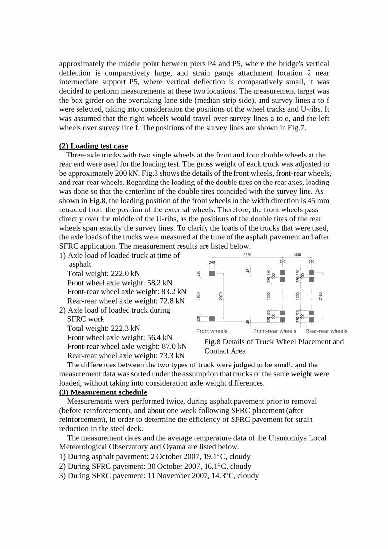
Three-axle trucks with two single wheels at the front and four double wheels at the rear end were used for the loading test. The gross weight of each truck was adjusted to be approximately 200 kN. Fig.8 shows the details of the front wheels, front-rear wheels, and rear-rear wheels. Regarding the loading of the double tires on the rear axes, loading was done so that the centerline of the double tires coincided with the survey line. As shown in Fig.8, the loading position of the front wheels in the width direction is 45 mm retracted from the position of the external wheels. Therefore, the front wheels pass directly over the middle of the U-ribs, as the positions of the double tires of the rear wheels span exactly the survey lines. To clarify the loads of the trucks that were used, the axle loads of the trucks were measured at the time of the asphalt pavement and after SFRC application. The measurement results are listed below. 1) Axle load of loaded truck at time of asphalt
Total weight: 222.0 kN Front wheel axle weight: 58.2 kN Front-rear wheel axle weight: 83.2 kN Rear-rear wheel axle weight: 72.8 kN
2) Axle load of loaded truck during SFRC work Total weight: 222.3 kN Front wheel axle weight: 56.4 kN Front-rear wheel axle weight: 87.0 kN Rear-rear wheel axle weight: 73.3 kN The differences between the two types of truck were judged to be small, and the
measurement data was sorted under the assumption that trucks of the same weight were loaded, without taking into consideration axle weight differences. (3) Measurement schedule
Measurements were performed twice, during asphalt pavement prior to removal (before reinforcement), and about one week following SFRC placement (after reinforcement), in order to determine the efficiency of SFRC pavement for strain reduction in the steel deck.
The measurement dates and the average temperature data of the Utsunomiya Local Meteorological Observatory and Oyama are listed below. 1) During asphalt pavement: 2 October 2007, 19.1°C, cloudy 2) During SFRC pavement: 30 October 2007, 16.1°C, cloudy 3) During SFRC pavement: 11 November 2007, 14.3°C, cloudy
Front wheels Front-rear wheels Rear-rear wheels
220
1850
220
220 100220
1300
220 100220
220 100220
1300
220 100220
240 240 240
3220 1330
2070
2160
45
45
Fig.8 Details of Truck Wheel Placement and Contact Area
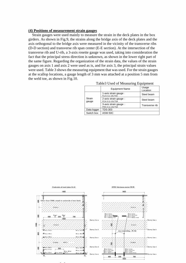
(4) Positions of measurement strain gauges Strain gauges were used mainly to measure the strain in the deck plates in the box
girders. As shown in Fig.9, the strains along the bridge axis of the deck plates and the axis orthogonal to the bridge axis were measured in the vicinity of the transverse ribs (D-D section) and transverse rib span center (E-E section). At the intersection of the transverse rib and U-rib, a 3-axis rosette gauge was used, taking into consideration the fact that the principal stress direction is unknown, as shown in the lower right part of the same figure. Regarding the organization of the strain data, the values of the strain gauges on axis 1 and axis 2 were used as is, and for axis 3, the principal strain values were used. Table 3 shows the measuring equipment that was used. For the strain gauges at the scallop locations, a gauge length of 3 mm was attached at a position 5 mm from the weld toe, as shown in Fig.10.
Equipment Name Usage Location
1-axis strain gauge:FLA-3-11-10LTSA Steel beam
2-axis strain gauge:FCA-3-11-10LTSA
Steel beam Strain gauge
3-axis strain gauge:FRA-3-11-10LTSA
Transverse rib
Data logger TDS-303 Switch box ASW-50C
Table3 Used of Measuring Equipment

Works At the attached steel plate on the steel-deck plate, removal of the existing asphalt
pavement by hands were executed paying attention to the position of bolts based on preliminary-survey results. In this case, the breaker that had an even edge so that damage may not be given to the steel deck plates was used. Much attention was paid especially so that damage might not be done to the bolt that was binding the attached steel plate tight. After removal of the existing asphalt pavement, the water jet machine stripped off all the water-resistant layers that remained on the deck plate.
As grinding processing in the deck plate to secure an excellent adhesion, the rust and foreign substances was removed by using two or more sets of shot blasting apparatuses. Small-sized apparatuses (0.35m in width) were used for the corner of steel deck plates, while large-sized apparatuses (1.0m in width) were used for the central part. In both sized apparatuses the density of shot blasting using steel balls of 1.4 mm in diameter was controlled by 300kg /m2. Application of epoxy resin adhesive started by 30 minutes before placing of SFRC and the speed of application was accommodated to the placing of SFRC.
Concrete with high-early-strength Portland cement and expansive admixture was manufactured in ready-mixed concrete plant and transported with agitator vehicles to the site. The steel fiber was put in the agitator car with the special device set up on the site, and mixed with concrete. The expansive admixture was used in order to reduce cracking due to drying shrinkage. After slump test and test for air content of the manufactured fresh SFRC samples was conducted to check the quality, the SFRC was discharged.
The SFRC was placed and compacted with a finisher. The SFRC was cured with plastic sheets for one day after placing and sprayed water for the following four days. Measurement and observations
To clarify the strain reducing effect of SFRC pavement, the results of comparisons before and after SFRC reinforcement at the strain gauges near deck plates, and comparisons before and after SFRC reinforcement, in other words at the time of the asphalt pavement and at the time of the SFRC pavement (hereafter, before and after SFRC reinforcement), at the strain gauges at the cross beams were compiled and sorted. The results are shown in Figure.11. The strain amplitude, which is the difference between the maximum strain and minimum strain during the passage of the trucks used in assessing fatigue durability performance, was used as the strain. The two-digit numbers and three-digit numbers in the strain gauge column indicate mid-span and P5 pier vicinity strain gauge attachment positions, respectively. Regarding the comparisons before and after SFRC reinforcement, the ratio (%) of the value after SFRC reinforcement (100 × value after reinforcement ÷ value before reinforcement) was used, defining the value before SFRC reinforcement as 100, and this numeric value is indicated at the right end of the strain amplitude (bar graph) in Fig.11. Particularly in the case of deck plates (shaded parts in Fig.11), this value was often 10% or lower. Looking at the strain values of the shaded parts, none of the gauges whose strain amplitude caused by wheel loads was on the order of 400 to 500 μ (84 to 105N/mm2) at the asphalt stage reach 100 μ (21 N/mm2). Moreover, regarding the welds of the deck plates and transverse ribs (E and F in

Fig.11), there are many gauges with values after SFRC pavement that have dropped to as low as 20% to 30% of the original value, a result showing that SFRC pavement is highly effective in reducing fatigue cracks in the steel deck. Conclusions
SFRC pavement was laid over a length of 213 m consisting of one 3-span continuous 2-box girder and two simple plate box girders of the inbound (Takasaki-bound) lanes of the Ohira Viaduct. Before and after reinforcement of the 3-span continuous 2-box girder that was selected for strain measurement, in other words when the pavement consisted of asphalt and SFRC, respectively, loading tests were performed. Trucks were used as the loads, and the reduction in strain obtained through SFRC pavement prior to opening of the bridge to traffic was investigated. The main findings are summarized below. 1) The strain reducing effect at deck plates locations is extremely large, particularly at the welds between deck plates and U-ribs, and in some cases, the strain value was reduced to as little as 1/10th the level following SFRC reinforcement. 2) Even at the welds between transverse ribs and U-ribs, the strain value was reduced to between 1/2 and 1/3 as the result of SFRC reinforcement, clearly attesting to the strain reducing effect of SFRC reinforcement, though to a lesser level than at deck plates.
B
C
D
F2
G1
A1
A2
E1
SymbolGauge
E2
G2
Strain Amplitude (μ)
F1
8
8
6
6
12
11
18
28
12
18
18
12
15
27
30
34
39
15
14
12
10
67
59
66
86
53
36
66
77
7
8
11
8
7
8
32
65
41
61
13
31
32
29
29
26
28
27
30
37
35
29
28
32
9
Before reinforcement
After reinforcement
0 100 200 300 400 500 600
47
49
50
147
149
150
53
54
55
153
154
155
51
151
56
156
60
160
2
5
102
105
14
17
20
23
114
117
120
123
7
9
10
107
109
110
25
26
27
125
126
127
38
39
40
138
139
140
30
33
36
130
133
136
Symbol Point of Focus Strain Direction
A1 Strain of deck plate
A2 Vertical strain of U-rib
B Weld between deck and vertical stiffeneStrain of deck plate
C Weld between main girder and vertical sVertical strain of main girder
D Stud weld of U-rib Strain of U-rib
E1 Strain of deck plate
E2 3-axis strain of transverse rib
F1 Strain of deck plate
F2 Vertical strain of U-rib
G1 3-axis strain of transverse rib
G2 Vertical strain of U-rib
Weld between deck plate and U-rib (U-rib span)
Weld between transverse rib and U-ribor deck plate
Weld between deck plate and U-rib(transverse rib crossing)
Weld between transverse rib and U-rib
Fig.11 Strain before and after SFRC Reinforcement

FINAL REMARKS The measurements conducted in the present study were carried out immediately after
reinforcement, when the reinforcing effect of SFRC can be expected to be greatest, and a large strain reducing effect believed to contribute to the improvement of fatigue durability of steel decks was observed. Even after the lapse of approximately four months under service following SFRC placement, no cracks were observed at the surface of the SFRC, and the placement of CFRP grids as a countermeasure [10] to prevent cracks in main girder webs is also believed to have an effect, but the occurrence of cracks to some extent in the future is still considered possible. Follow-ups will be done and the effect of the SFRC pavement that was placed this time as a fatigue countermeasure for the steel deck, the persistence of this effect, the durability of the pavement proper, and other aspects will be examined.
REFERENCES 1. Nishikawa, Steel deck surfacing with SFRC—A New Relationship between Steel
and Concrete, Bridge and Foundation Engineering, August 2005, pp. 84-87. 2. Yamada, Fatigue Damage of Steel Plate Decks under Heavy Traffic—Cases around
Nagoya, Japan Society of Civil Engineers, 10th Symposium on Steel Structures and Bridges. August 2007.
3. Satoh et al., Composite Effect of Steel Deck Surfaced with Steel Fiber Reinforced Concrete Pavement, Steel Structures and Bridges, February 1986, pp. 26-30.
4. Kagata et al., Measures against Fatigue Damage of Steel Decks through SFRC Paving—The Case of Paving Work on National Highway 357's Yokohama Bay Bridge, Steel Structures and Bridges, October 2004, pp. 27-32.
5. Yamada, Fatigue Reducing Effect of SFR Pavement on Steel Decks, 62nd Annual Conference of the Japan Society of Civil Engineers, September 2007.
6. Kikuchi et al., Fatigue Countermeasures for Steel Plate Deck of Shonan-Ohashi Bridge, Japan Society of Civil Engineers, 10th Symposium on Steel Structures and Bridges. August 2007.
7. Kodama et al., Fatigue Countermeasures for Steel Decks using SFRC during In-Service Period, Bridge and Foundation Engineering, November 2006, pp. 30-38.
8. Kogoshi et al., Measurement of Effect of SFRC Reinforcement of Existing Steel Decks of Bridges," 62nd Annual Conference of the Japan Society of Civil Engineers, September 2007.
9. Ono et al., "Water Immersion/Wheel Load Fatigue Test for Steel Deck Surfaced with Steel Fiber Reinforced Concrete, 62nd Annual Conference of the Japan Society of Civil Engineers, September 2007.
10. Hitose et al., A Study on Rebars for Increasing Durability of SFRC Pavement on Steel Plate Decks, 62nd Annual Conference of the Japan Society of Civil Engineers, September 2007.

blank