effect of shrinkage onservice performance of steel...
TRANSCRIPT

Effect of Shrinkage onService Performance of Steel Castings
Richard Hardin and Christoph Beckermann
Department of Mechanical and Industrial Engineering,University of Iowa, Iowa City, IA
ABSTRACT
An overview of the objectives and progress made by the “Integrated Design of Steel Castingsfor Service Performance” research program is presented. The methods being used in the program topredict the structural service performance of steel castings with porosity are reviewed. Structuralperformance predictions are given for a commercial steel casting applying the methods to knownporosity defects detected by radiography. These are compared with measurements. Next, exampleresults are computed for service life throughout an entire casting using a predicted porosity field. Theapproach being taken to experimentally validate the effect of shrinkage discontinuities is described.Results from this project task; the generation of test specimens having varying degrees of soundness ispresented. Future work and project plans are summarized.

2
1. INTRODUCTION
A primary concern of every steel foundryman is producing the highest quality steel castingdespite many constraints placed upon them. Consistently high quality is not easy to achieve. As thereader well knows, it comes through knowledge and expertise in casting, and attention to the castingprocess details. It also comes at increased time and production costs, and the cost of improvingtechnology. Fortunately the highest level of casting quality is not warranted, nor is it usually required formost commercial steel castings. It is safe to say that in almost all cases, the level of casting quality andsoundness required by part designers is not presently based on engineering principles, but their own ortheir workgroup’s experience and practice. These soundness requirements impose many constraints onfoundries and limit the market for castings. Because of this, validated engineering methods for analyzingand predicting the structural performance of cast parts with advanced models of the as-cast materialcould revolutionize the casting industry. Such advanced modeling would take into account the castingprocess and incorporate porosity into the prediction of part strength and durability, or fatigue life. Thedevelopment of engineering approaches to analyze, to better understand and predict casting“soundness” quality and its effect on casting structural performance in service, is the focus of this work.
The determination of a steel casting’s “soundness” quality is based on non-destructiveexamination (NDE) techniques; radiography, ultrasonic, eddy current, magnetic particle and dyepenetrant testing. The relationship between quality level and the structural performance of the part inservice is rather speculative unless the designer requires the part to be the highest class of quality, i.e.entirely sound with no surface imperfections. Part designers have long had their own notions about thesignificance of levels of quality determined by these NDE methods and their relationship to castingstructural performance, and these vary depending on the designer. Sometimes NDE standards areapplied as if they were directly related to the casting service performance, which is a misunderstandingor misuse of the standards. In other words, NDE standards are often used as if they were structuralperformance related standards, when they are actually workmanship standards.
Lacking an engineering approach that considers casting soundness, design engineers may beover specifying the required casting soundness, over designing the casting with excessive safety factors,or may misapply the NDE standards required for the part. Over specifying the casting might result inincreased costs, or might result in a part that is not casting friendly, or even the part is deemed not“castable”. Over designing the casting results in a heavier casting, and perpetuates the myth thatcastings cannot be lightweight. Misapplying the NDE standards may result in specifying excellentinterior soundness though the part might fail during service from fatigue due to an undetecteddiscontinuity at the casting surface.
2. PROJECT OVERVIEW
As a response to the issues raised above, it is not proposed that steel foundries make moreunsound castings, but rather that they and the part designers begin to consider soundness in the partdesign in a more advanced way. Once designers can relate x-ray standards to part structural
3
performance, fewer castings will be produced and rejected when not necessary, and likewise, fewercastings will pass radiographic testing when they should not. From this work, engineering guidelines thatrelate casting soundness to structural performance in service will begin to evolve, and it is envisionedthat this work will result in an increase in customer confidence in steel castings and in casting structuralperformance.
The present work couples casting simulation and finite element stress analysis (FEA orFEM) to predict the load-carrying capacity and durability. In order to begin to use predictive modelsfor durability prediction in the presence of porosity, not only must casting simulation codes be able topredict the location, distribution, and size of shrinkage discontinuities, but also information about itsshape. The smooth surface of a gas pore will very likely behave differently than the jagged surface ofdendrites associated with a macro-shrinkage produced cavity. Using a stress analysis model that usesthe above-mentioned information from a casting simulation, the effect of the shrinkage discontinuities onthe structural performance of a cast steel component will be predicted in this study. High-resolutionradiography and strength/fatigue tests will be used to validate the model predictions. The integratedcasting simulation/stress analysis tool developed in this project will then allow for simultaneousoptimization of the casting process parameters (e.g., riser location) and the component geometry (e.g.,section thickness) at an early stage in the product definition, as shown schematically in Figure 1. Thenew predictive methods will be tested on selected commercial steel castings. Improved radiographicinspection standards will be established that take into account the size and location of shrinkagediscontinuities on the structural performance of steel castings. New guidelines for the design of steelcastings will ultimately result.
This research program, “Integrated Design of Steel Castings for Service Performance”,has ambitious objectives; to validate the analysis methods for casting soundness and structuralperformance prediction developed through radiographic and mechanical testing, and to ultimatelypropose new design guidelines and improved inspection standards. At present, this research program isapproximately midway through a 42-month planned duration. Expected benefits of the project are:
• Data on the effect of shrinkage discontinuities on the mechanical properties and structuralperformance of steel castings.
• A validated simulation tool that predicts the location and amount of shrinkage discontinuities andquantitatively evaluates the load-carrying capacity and fatigue durability of a cast componentcontaining the discontinuities.
• Improved capability to design steel castings with non-uniform mechanical properties (allow adiscontinuity where it can be tolerated, ensure soundness where needed) and examine thetradeoffs between manufacturing costs and structural performance.
• New design guidelines based on meaningful radiographic inspection standards.
Other outcomes of the project should be improved designer and end user confidence in steel castings,decreased casting weight, increased casting yield, new applications for steel castings, and reduced leadtime and cost through fewer design iterations.
4
3. REVIEW OF PREVIOUS WORK
ASTM radiographic standards are presently used to specify the allowable level (orseverity) of shrinkage discontinuities in a steel casting. Therefore, this work investigates the effect ofshrinkage discontinuities that are detected using the ASTM radiographic standards for steel castings(ASTM E446, E186 and E280) on the structural performance of carbon and low alloy steel castings.Current ASTM standards for radiographic testing of castings provide only a qualitative basis uponwhich to accept or reject castings, and the accuracy in the x-ray rating is probably at best only ± 1 x-ray rating grades [1, 2]. Also, under the present ASTM standards, it is entirely possible, for example,for the small defect near the surface to be passed whereas a larger, centerline shrinkage causes rejectionof the casting. This example may result in two failures of the desired inspection. Rejection of a castingthat should not be rejected, since previous work indicates that a large level of discontinuities located inthe center of a casting section may not affect mechanical properties or fatigue structural performance ofthe component [3 – 6]. Acceptance of a casting that should not be accepted, since a small discontinuitynear a surface may have a significant effect on fatigue life [4, 7, 8]. Consequently, the design engineeruses large safety factors, over-specifies the casting making it expensive to produce, or possibly rejectsthe use of steel castings altogether [9].
Twelve casting strength/performance case studies were conducted [10] thatdemonstrated internal discontinuities such as shrinkage porosity had little effect on the strengthperformance of the castings. However, when discontinuities appeared at the surface, or were broughtthere by machining, there was a drop off in strength, particularly if the surface area was in high stress. Itwas thought that different results on the importance of internal casting discontinuities might be obtained ifdynamic loading was considered instead [4]. In dynamic (fatigue) loading, it was observed that internaldiscontinuities detected by radiography (considered “unacceptable” by the standards) had little effect onthe service life of the steel castings in the study. On the other hand, it was found that surfacediscontinuities in stress concentration areas had a severe detrimental effect on service life [4]. Anotherimportant outcome was that even the most severe surface indications detected using ASTM E-125magnetic particle inspection appeared to have less an effect on measured endurance properties thansuggested by notched fatigue data.
In the area of fatigue of cast metals there is significant research investigating materialproperties and modeling the durability of castings with discontinuities such as porosity and inclusions.There is little work found in the literature where integration of casting process simulation, or predictingthe porosity, and durability modeling are studied concurrently. Life estimation in fatigue analysis isusually considered in two stages [11, p. 231]. The first of these is the “crack initiation” or “cracknucleation” stage, and the second is the “crack growth” stage. Prediction of the duration of the firststage of “life” for a component is usually performed using the strain-life (or ε-N) approach [11, pp. 93-117]. This initial stage of life and the strain-life models presented in [11] predict the duration of life toinitiate a crack on the order of 1 mm. One may use this concept to determine the crack initiation life in acasting in the presence of porosity by modeling the pore as a notch. Researchers studying aluminumcastings have treated pores in castings as notches in order to predict the effect of porosity on crack

5
initiation life [12], and also the mechanism of crack formation from pores has been investigated recently[13].
The second stage of fatigue life, the “fatigue crack growth” stage, has a very critical rolein damage-tolerant design life prediction, particularly in nuclear and aerospace applications. It presumesthe presence of a crack, formed either from fatigue or during manufacturing of the part. It is applicableto inclusions and porosity in steel casting. Not surprisingly, it appears to be the most commonly appliedmethod used in the literature for analyzing the life of cast components with porosity. Commonly usedmodels to predict crack growth arise from the concepts of fracture mechanics, in particular linear elasticfracture mechanics (LEFM) [11, pp.122-173]. An excellent overview of the use of fracture mechanicswith application to steel castings is given by Jackson [14] from the SCRATA. Quite recentlyHorstemeyer et al. [15-17] have used crack growth fracture mechanics to map failure, optimize partgeometry, and predict fatigue life in aluminum castings in the presence of inclusions, porosity, andmicrostructural variations. Fatigue life investigations for cast metals with porosity by fracture mechanicsapproaches are available for a variety of metals and alloys such as titanium [18], nodular cast iron [19],nickel-aluminum bronze [20]. However, interest in cast aluminum alloys appears to predominate theliterature [15-17,21-24].
Of immediate interest to the reader is the literature available on steel castings. Modelingand experimental studies on the effect of steel casting defects and porosity on fatigue life using fracturemechanics and crack growth models is well summarized by Jayet-Gendrot at al. [25]. Experimentalwork on the effect of porosity on the fatigue strength of cast steel reveals that reductions in fatiguestrength of 35% and 50% are observed for “sizes” (areas of cavities) of less than and greater than 3mm2, respectively, for cast 13 Cr stainless steel [26]. For low alloy steel, fatigue strength reductionsfrom 8 to 30% were found when shrinkage porosity cavities covered 3 to 7% of the fracture surface[27]. Heuler et al. [28] present a comparison between the measured fatigue life of test specimenscontaining casting defects (porosity and inclusions) and the fatigue life obtained by modeling thespecimen using crack initiation (local strain and stain life concepts) and crack propagation (fracturemechanics) approaches. For the crack growth model, Heuler et al. treated the casting defects as 2-Delliptical cracks having an envelope about the defect, and the defects were considered to be 3-Dnotches in the crack initiation model. Heuler et al. [28] found that the crack initiation estimate of life wasmore accurate than the fracture mechanics approach. They found that interpreting the defects as cracksresulted in too conservative an estimate of the fatigue life. Dabayeh and Topper [21] came to asomewhat different conclusion for cast aluminum where the local strain approach gave quite un-conservative estimates of fatigue life, and the crack growth method gave good agreement.
Stephens et al. [29] provide benchmark fatigue property data for nominally sound caststeels: SAE 003 normalized and tempered (NT), SAE 0050A NT, low alloy C-Mn normalized,quenched and tempered (NQT), low alloy Mn-Mo (NQT), and AISI 8630 (NQT). The specimensmeasured were deemed nominally sound, but all five cast steels were reported to contain “the usualinclusions and porosity.” An exception was observed in some 8630 specimens that were observed tohave an unusually low reduction in area, but fractographic analysis gave 20% to 30% porosity in thosespecimens. Property data and model parameter data included in [29] are monotonic stress-strain (σ-ε)behavior, cyclic stress-strain (σ’-ε’) behavior, low cycle fatigue behavior data (provides parametersneeded in strain-life models), and fatigue crack propagation behavior data (provides parameters needed

6
in crack-growth models). Prof. Stephens was asked and agreed to participate in the current project toproduce additional fatigue property data for AISI 8630 steel specimens with varying degrees ofporosity in them. Using the data in [29] as base-line “sound” material data, measurements will be madefor the current project using sound and unsound specimens for comparison with prediction and themeasurements made earlier.
4. CURRENT WORK AND RESULTS
An integrated approach involving both numerical and experimental methods is being undertakento meet the objectives of this research project. Up to this point in the project, work has beenperformed on the following items with results example calculations provided.
4.1 Computational Models for Casting Simulation and Stress/Durability Analysis
An improved simulation model has been developed to predict the amount and location of shrinkagediscontinuities in steel castings. This model has been implemented into a commonly used castingsimulation code, MAGMAsoft [30]. This paper [30] is presented at this T&O Conference, andprovides all model details along with example results; it will not be discussed further here.
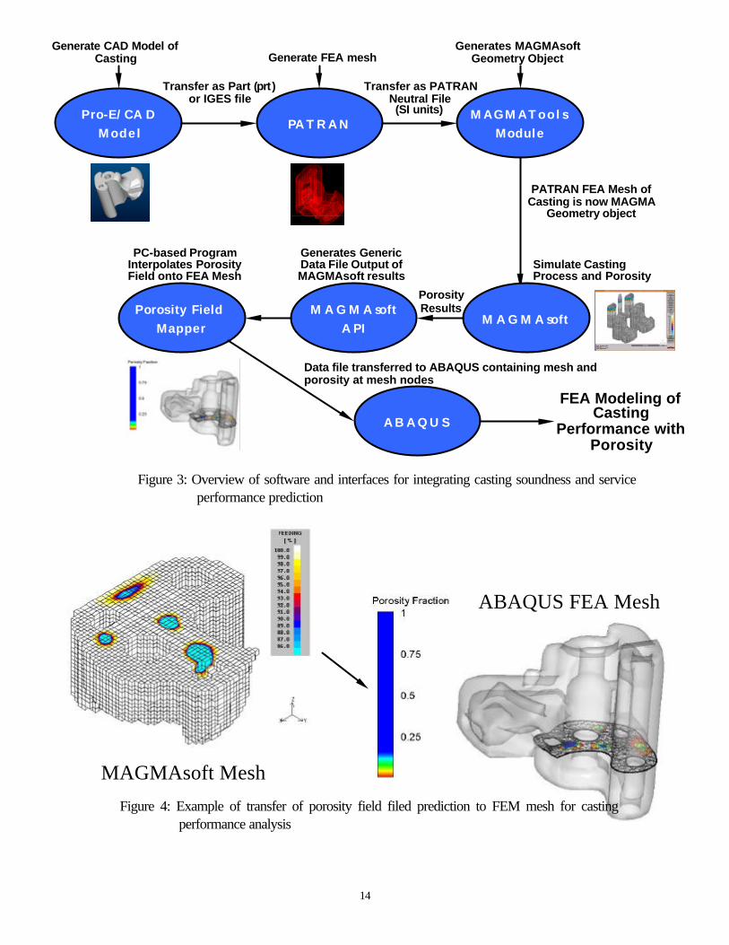
Interfaces between existing (commercial) software and a new computational model have beendeveloped to predict the load-carrying capacity and fatigue durability of steel castings in the presence ofshrinkage discontinuities as presented in Figures 2 and 3. An existing model is being employed for staticstrength based on the porous-metal plasticity theory for stress analysis using FEA in the commercialcode ABAQUS (see Figure 2), which is commonly used in the industry. An interface has beendeveloped to transfer the porosity field predicted by MAGMAsoft onto the finite element mesh asoutlined in Figure 3 and graphically demonstrated in Figure 4. Using this integrated model and predicteddistribution of shrinkage discontinuities and base metal properties, the strength and fatigue life of caststeel products can be predicted.
The approach and methodology used to analyze the casting service performance was developedat the University of Iowa by Prof. Sharif Rahman and his graduate student Dong Wei for this project.Their methods are as outlined in [11] for the two stages of fatigue life discussed earlier in the literaturereview. The calculations are outlined in Figures 5 and 6 for the crack initiation and fatigue crack growthanalyses, respectively. The method used to analyze the static strength is the porous metal plasticitymodel available in the ABAQUS software. To test the casting structural performance analysis methods,a commercial casting with known documented shrinkage in [4] was chosen for static and fatigueanalysis. This casting and simulation mesh are shown in Figure 7. Although the casting rigging andparameters are not given in [4], the internal shrinkage typical of the process is given. A casting riggingwhich gives the same internal soundness as reported in [4] was determined and used in castingsimulations. The static strength testing and simulated results are shown in Figures 8 and 9, where theinternal porosity in the casting is simulated using the ABAQUS porous metal plasticity model. There isgood agreement up to large displacements in the experimental and simulated results. This casting is

7
reported in [4] to fail at the location of highest stress in static testing, and the porosity does not play arole. This observation is typical for all castings presented in [4].
Fatigue predictions using the two methods of life prediction with “known” defects taken from x-rays in [4] were conducted as outlined in Figures 10 through 12. Using the x-rays, defects at twosurface locations were identified (nodes A and B). At node A, a parameteric study was performedusing four sizes of defect 0, 0.25, 0.5, and 1 mm as shown in Figure 10. Note that four internal defectswere also identified and analyzed (nodes C, D, E, and F in Figure 10). The fatigue life at each nodedetermined by modeling the part loading as given in [4] in ABAQUS and transferring the stress andstrain results to the fatigue calculations. The fatigue crack initiation life is shown in Figure 11, and thecrack propagation life is shown in Figure 12. The results showed that using the 0.5 mm diameter defectat the high stress location gives the best agreement with the test results for the crack initiation model,followed by the other surface node and the internal node C. The results change somewhat comparingthe crack growth model results in Figure 12, where the surface node B and internal node C are themore conservative and better agreeing results. Following these initial comparisons with known defects,it was determined that neither method for prediction stood out over the other. Although, the modelshown in Figure 11 appears to better predict the life at the position of maximum stress (near node A),and the trend in load versus life is somewhat better.
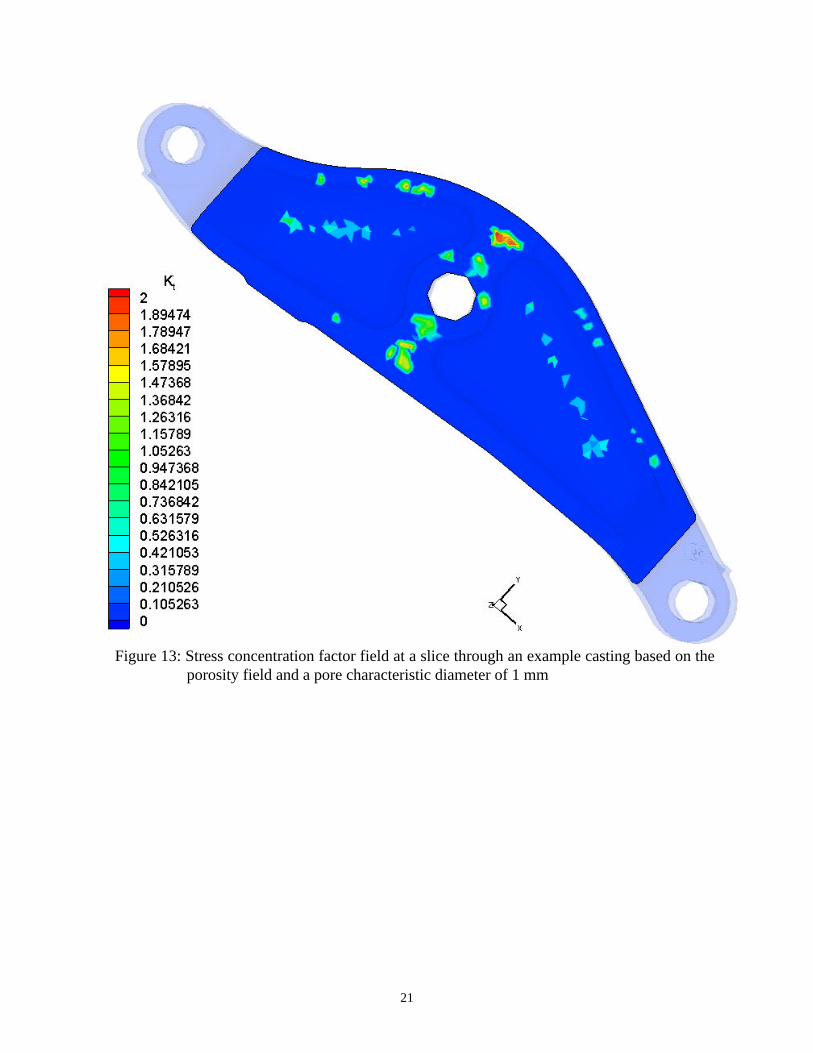
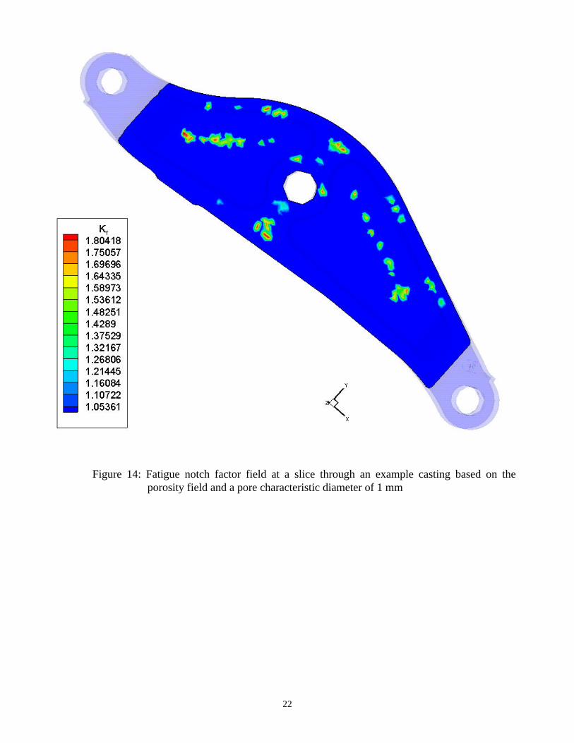
Based on these initial studies, it was determined to first focus on crack initiation life predictions.Methods were developed to automate the calculations on the finite element mesh, and a fully integratedmodel is demonstrated on an example casting in Figures 13 to 16. The example casting was actually acase study casting that was entirely sound as produced, and any porosity data shown in the plots ispurely for demonstration purposes. Porosity was introduced by manipulating the simulations forpurposes of demonstrating the modeling. In Figure 13, the stress concentration factor (Kt) field resultingfrom the porosity is shown. In this case, Kt was determined assuming the porosity to be a distributionof 1 mm diameter pores and standard formulas for holes of uniform spacing were used [31,32]. Ingeneral, Kt can be determined by notch shape and loading type/direction, also it depends on location(surface, near surface or deep inside). A more sophisticated approach for determining Kt in the modelshould be incorporated in the final version. From the Kt field, the fatigue notch field (Kf) may bedetermined [32] as shown in Figure 14, for the same slice as Figure 13. Using the approach outlined inFigure 5 [11], the strain life for crack initiation can be calculated. For the case of no porosity, Kt andKf are 1, a life distribution throughout the part such as that shown in Figure 15 results. Considering theporosity, and using the Kt and Kf fields shown in Figure 13 and 14, respectively, a different lifedistribution results which includes a few additional low life “hot spots” as shown in Figure 16.
4.2 Experimental Validations and Effect of Shrinkage Discontinuities
The computational models for casting simulation and stress/durability prediction will be verified withthe experimental data. Although this part of the project is not completed (scheduled for completion inFebruary 2003), here is an update on the progress. Test castings were produced with a range ofsoundness as can be detect using normal ASTM radiographic standards. Figure 17 shows the castingsused to generated the test specimens, and the finished specimen shown in Figure 18 will be machined

8
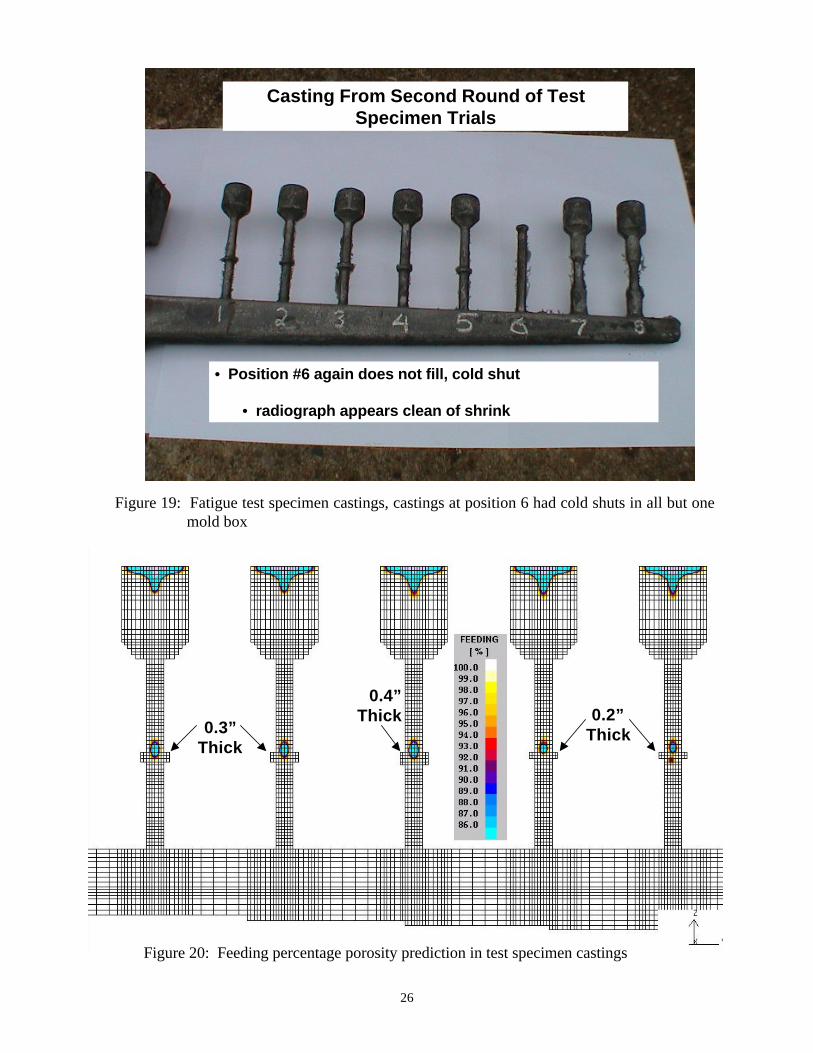
out the test blank castings. The test casting blanks and rigging are shown in Figure 19. The predictionsof the “feeding percentage” porosity for the specimen castings are shown in Figure 20, whileradiographs of the specimens are shown in Figure 21. The shrinkage in the casting is relativelysymmetric about the center of the specimen center length, at the disk location. The improved porositypredictor [30] results in a porosity distribution shown in Figure 22; this more closely agrees with theactual porosity. The two “lobed” appearance in some of the predictions is believed to be an artifactfrom interpolation. Radiographs of as-cast and final machined fatigue test specimens (as shown in Figure23) were taken. The objective of future work is to validate the shrinkage predictions from castingsimulation model using digital analysis of the x-ray images, and use them to characterize the specimensoundness. Mechanical tests are presently being performed to validate the predicted strength and fatiguelife from the computational stress/durability model amounts of shrinkage discontinuities. Followingvalidation of computational models, further stress/durability analyses will be performed with the model toevaluate the effect of shrinkage discontinuities on static strength and fatigue properties of cast steel.
4.3 Structural Performance of Mechanical Components and Relationship withRadiographic Standards
Following discussions with DoD and industrial sponsors and collaborators, representativeproduction steel casting components typically used in the industry have been selected for study.Although this work is not scheduled to begin until February 2003, substantial progress has already beenmade by identification of participant companies, components, and beginning work on them. HarrisonSteel Casting Company, Caterpillar, Packer Technologies International Inc., Huron Casting Inc., andOshkosh Truck Corp. will be participating. The shrinkage distribution will be quantified through castingsimulation and x-ray testing. The distribution will then be used as input to the experimentally validatedmodel for stress/durability analysis. Using this methodology, the mechanical performance of the castingwill be examined. A limited number of experiments will also be performed to validate the predictions.The integrated casting simulation/stress/durability analysis method will be used to investigate the effectsof changes in certain casting process parameters (such as riser locations) and component geometry(such as section thickness) on the service performance of the selected components. The goal is toachieve more optimized casting processes and component designs. A quantitative relationship betweenservice performance and radiographic inspection measures will be established.
5. CONCLUSION
Presently, designers have no quantitative engineering principles to follow for the selection of adesired level of casting quality and, consequently, use overly large safety factors or reject the use ofsteel castings. The lack of a precise, structural performance-based standard leads to castings that arerejected when not necessary, and castings passing radiographic testing when they should not pass. Amethod for the analysis of the structural service performance steel castings has been developed, butmuch work remains to validate and determine its range of applicability. From this work and themodeling tools that will be developed, it is envisioned that engineering guidelines relating castingsoundness to structural performance in service can be developed.
9
ACKNOWLEDGMENTS
This report was prepared with, and the project work was conducted with, support from theUnited States Department of Defense through the American Metalcasting Consortium (AMC) PRO-ACT program. AMC’s PRO-ACT program is sponsored by Defense Supply Center Philadelphia(DSC, Philadelphia, PA) and the Defense Logistics Agency (DLA, Ft. Belvoir, VA). This researchprogram, Integrated Design of Steel Castings for Service Performance, is conducted under the auspicesof the Steel Founders' Society of America. We gratefully acknowledge the support of Malcolm Blairand Raymond Monroe of the SFSA. Most importantly, perhaps, this research program would not bepossible without substantial in-kind support and interest from SFSA member foundries. They havecontributed substantially to this research project through guidance and participation. In particular, wewould like to thank Harrison Steel for their efforts in casting several trial iterations of test specimens, andthe final eighty test specimen castings. We would like to acknowledge the contributions made to theproject by Prof. Sharif Rahman and his student Dong Wei, who devised and performed the initialstructural performance predictions contained in this paper. We would like to thank the companies thathave agreed to participate in our casting case studies: Harrison Steel Casting Company, Caterpillar,Packer Technologies International Inc., Huron Casting Inc., and Oshkosh Truck Corp. Weacknowledge the timely assistance of Alloy Weld Inspection Co. for their digital and film radiography ofthe fatigue test specimens. Any opinions, findings, conclusions, or recommendations expressed hereinare those of the authors and do not necessarily reflect the views of DSC, DLA, or the SFSA and any ofits member foundries.
REFERENCES
[1] Quantrell, R., “Evaluation of the Consistency of Radiographic Grading for Shrinkage Defects,”SCRATA Committee Paper, 1981.
[2] Carlson, K., Ou, S., Hardin, R. and Beckermann, C., “Analysis of ASTM X-Ray ShrinkageRating for Steel Castings,” 2000 SFSA Technical and Operating Conference Proceedings,2000.
[3] Wallace, J. F., et al., Effect of Shrinkage Porosity on Mechanical Properties of SteelCasting Sections, Steel Foundry Research Foundation Report, SFRF, 1962.
[4] Vishnevshy, C., Bertolino, M. and Wallace, J. F., The Evaluation of Discontinuities inCommercial Steel Castings by Dynamic Loading to Failure in Fatigue, Steel FoundryResearch Foundation Report, SFRF, 1967.
[5] Wallace, J. F., et al., The Effect of Internal Shrinkage Discontinuities on the Fatigue andImpact Properties of Cast Steel Sections, Steel Foundry Research Foundation Report,SFRF, 1969.

10
[6] Larson, H. R., et al., “Comparison of X-ray Quality and Tensile Properties on Cast HighStrength Steel,” AFS Transactions, Vol. 100, pp. 676-684, 1959.
[7] Wallace, J. F., et al., The Effect of Surface Discontinuities on the Fatigue Properties ofCast Steel Sections, Steel Foundry Research Foundation Report, SFRF, 1966.
[8] Wallace, J. F., et al., Impact Properties of Cast Steel Sections with Surface Discontinuities,Steel Foundry Research Foundation Report, SFRF, 1967.
[9] Gwyn, M., “Cost-Effective Casting Design,” Modern Casting, Vol. 88, No. 5, pp. 32-36,1998.
[10] Choi, C., Miller, W., Oberacker, D., Turnbull, G., Wallace, J. and Wright D., Correlation ofDestructive Testing of Steel Castings with Stress Analysis and Mechanical Properties,Steel Foundry Research Foundation Report, SFRF, 1962.
[11] Stephens, R.I., Fatemi, A., Stephens, R.R., and Fuchs, H.O., Metal Fatigue in Engineering,John Wiley and Sons, 2001.
[12] Sonsino, C., and Ziese, J., “Fatigue Strength and Applications of Cast Aluminum Alloy withDifferent Degrees of Porosity”, Int. Journal of Fatigue, vol. 15(2), pp. 75-84, March, 1993.
[13] Buffiere, J-Y., Savelli, S., Jouneau, P.H., Maire, e., and Fougeres, R., “Experimental Study ofPorosity and its Relation to Fatigue Mechanisms of Model Al-Si7-Mg0.3 Cast A1 Alloys”,Materials Science and Engineering A316, pp. 115-126, 2001.
[14] Jackson, W. J., Fracture Toughness in Relation to Steel Castings Design and Application,SFSA, 1978.
[15] Horstemeyer, M.F., “Mapping Failure by Microstructure-Property Modeling,” JOM, pp. 24-27, September, 2001.
[16] Horstemeyer, M.F., Osborne, R.J., and Penrod, D.E., “Microstructure-Property Analysis andOptimization of Control Arm,” AFS Transactions 02-036.
[17] McDowell, D.L., Gall, K., Horstemeyer, and Fan, J., “Microstructure-based Fatigue Modelingof Cast A356-T6 Alloy,” Engineering Fracture Mechanics, article in press, 2002.
[18] Petty-Galis, J.L., Goolsby, R.D., and Osborn, L.M., “Investigation of Fatigue Behavior of CastTi-15V-3Al-3Cr-3Sn,” Microstructure/Property Relationships in Titanium Aluminides andAlloys, Young-Won and Boyer eds., TMS, pp. 563-578, 1991.
11
[19] Mansson, T., and F. Nilsson, ”Fatigue Life Estimation of Cast Components”, Int. Journal ofCast Metals Research, v. 13, pp. 373-378, 2001.
[20] Taylor, D., and Knott, J.F., “Growth of Fatigue Cracks from Casting defects in Nickel-Aluminum Bronze,” Metals Technology, Vol. 9, pp. 221-228, 1982.
[21] Dabayeh, A., and Topper, T. H., “Fatigue of Casting Flaws at a Notch Root under an SAEService Load History,” Fatigue Fracture Engng. Mater. Struct., vol. 23, pp. 993-1006,2000.
[22] Dabayeh, A., Berube, A. and Topper, T. H., “An Experimental Study of the Effect of a Flaw ata Notch Root on the Fatigue life of Cast Al 319,” Int. Journal of Fatigue, vol. 20(7), pp.517-530, 1998.
[23] Skallerud, B., Iveland, T. and Harkegard, G., “Fatigue Life Assessment of Aluminum Alloyswith Casting Defects,” Engineering Fracture Mechanics, Vol. 44(6), pp. 857-874, 1993.
[24] Wang, Q., Apelian, D., and Lados, D., “Fatigue Behavior of A356-T6 Aluminum Cast Alloys.Part I. Effect of Casting Defects,” Journal of Light Metals, pp. 73-84, 2001.
[25] Jayet-Gendrot, S., Gilles, P. and Migne, C., “Behavior of Duplex Stainless Steel CastingDefects under Mechanical Loadings,” Fatigue and Fracture: 1997 PVP-Vol. 350, vol. 1,ASME, pp. 107-116, 1997.
[26] Kohno M., Makioka M., "Some Studies on the Manufacture of Cast 13 Chrome StainlessSteel Francis Type Runners for Hydraulic Turbines", AFS Transactions, vol. 78, pp. 9-16,1970.
[27] Chijiwa K., Nakayama T., and Imamura M., “Effect of Casting Defects upon the EnduranceLimit of Large Steel Castings," 35e CIF, pp. 36-1 to 36-12.
[28] Heuler P., Berger C., Motz J., "Fatigue Behaviour of Steel Castings Containing Near-SurfaceDefects," Fatigue Fracture Engng. Mater. Struct. Vol. 16(1), pp. 115-136, 1992.
[29] Stephens, R.I., Fatigue and Fracture Toughness of Five Carbon or Low Alloy Cast Steelsat Room or Low Climatic Temperatures, SFSA Research Report Nos. 94A and 94B, 1982.
[30] K. Carlson, Z. Lin, R. Hardin and C. Beckermann, “Modeling Of Porosity Formation AndFeeding Flow In Steel Casting,” 2002 SFSA Technical and Operating ConferenceProceedings, 2002.
[31] Nueber, H., Kerbspannungstehre, Springer, Berlin, 1958; In Translation, Theory of NotchStresses, U.S. Office of Technical Services, Washington, D.C., 1961.

12
[32] Peterson, R.E., Stress Concentration Factors, John Wiley and Sons, New York, 1974.

13
Figure 1: Illustration of Integrated Design of Steel Castings for Service Performance.
Casting Simulation(Shrinkage Prediction)
Stress Analysis(Strength, FatigueLife Prediction)
RadiographicTesting
ShrinkageDiscontinuities
NewDesignGuidelines
Iterate on geometry and rigging
OptimizedServicePerformance
ImprovedInspectionStandards
Already Exists
PA RTC A D
MODEL
• Geometry Information• Definition of Solids/Surfaces
FEM INPUTDECK
• FEM Mesh• FEM Input File
PRO/E
A BA Q U S / C A E
FEMSTRESS
ANALYSIS
• Linear-Elastic or Elastic-Plastic Analysis• Calculation of Stresses/Strains
PA T R A NA BA Q U S
A BA Q U S / C A E
FA T I G U ELIFE
ANALYSIS
• LSC and/or FCG Analysis• Assessment of Durability
“ I N - H O U S E ”
M o d e l
Exists Newly Developed
Figure 2: Overview of software used in analysis of service performance
14
PA T R A NPro-E/CA D
Model
Transfer as Part (prt)or IGES file
Generate CAD Model ofCasting Generate FEA mesh
MAGMAToo lsModule
Transfer as PATRANNeutral File(SI units)
Generates MAGMAsoftGeometry Object
M A G M A softM A G M A soft
A PIPorosity Field
Mapper
PC-based ProgramInterpolates PorosityField onto FEA Mesh
Generates GenericData File Output ofMAGMAsoft results
Simulate CastingProcess and Porosity
PATRAN FEA Mesh ofCasting is now MAGMA
Geometry object
PorosityResults
A B A Q U S
Data file transferred to ABAQUS containing mesh and porosity at mesh nodes
FEA Modeling ofCasting
Performance withPorosity
Figure 3: Overview of software and interfaces for integrating casting soundness and serviceperformance prediction
MAGMAsoft Mesh
ABAQUS FEA Mesh
Figure 4: Example of transfer of porosity field filed prediction to FEM mesh for castingperformance analysis

15
Calculate Stress Conc. Factor (Kt)
• Ellipsoidal Notch (Internal/Surface)• Kt from Neuber’s, Eubanks’, and Tsuchida’s Formula
Calculate Fatigue Notch Factor (Kf)
• Peterson Formula or Others
( )1 1f tK q K= + −
Calculate Local Stress/Strain Fields
• Linear Rule, Neuber’s Rule, Glinka’s Rule
2fK S e∆ε∆σ = ∆ ∆
Calculate “Crack Initiation” Life
2(2 ) (2 )f b c
f f fN NE
ε ′σ∆ ′= + ε
Conduct FEA with No Defects
Nf = ?Obtain:
, S e∆ ∆
Figure 5: Schematic overview of calculation of method used to predict crack initiation life basedon strain-life approach [11]

16
Characterize Initial Crack Size (a0)
Calculate Crack Driving Force (SIF)
F = Geom. Factor (Newman-Raju)σ = Max. principle stress (FEM)
Apply Paris Equation for FCG
Conduct FEA with No Defects
Nf = ?Obtain:
, S e∆ ∆ 0 0 ; ellip. crack (internal/surface)a A=
IK F a∆ = ∆σ π
A0 = defect area in the planeperpend. to max. prin. direction
( ) 0 0; (0)m
I
daC K a a A
dN= ∆ = =
Calculate “Crack Propagation” Life1 2 4
02
1 1
( ) 2 1
m
f m m m
AN
CF m
−
=∆σ π −
Figure 6: Schematic overview of calculation of method used to predict fatigue crack growth (FSG)of propagation life based on fracture mechanics approach [11]

17
Load, P
(Fixed BC)
Diameter of CenterlineShrinkage = 0.0575 in
Figure 7: Hanger casting from [4] used to test casting performance prediction methods
Figure 8: Hanger casting deformed by static strength testing in experiment (above left from[4]) and under the same loads using FEM analysis
ExperimentFEM Analysis

18
0.0 0.4 0.8 1.2 1.6 2.0
RMS Displacement, in
0
2000
4000
6000
8000
10000
Loa
d (P
), lb FEM
Experiment
Figure 9: Load vs. displacement results of hanger casting from experiment [4] and from FEManalysis using porous metal plasticity model in ABAQUS
A
DE
F
C
B
Surface Defect:Node A: Dh = 0, 0.25, 0.5, 1 mm; a/b = 1Node B: Dh = 5 mm; a/b = 1.33
Internal Defect:Node C: Dh = 6 mm; a/b = 1Node D: Dh = 2.3 mm; a/b = 1Node E: Dh = 1.6 mm; a/b = 1Node F: Dh = 2.5 mm; a/b = 1
2a
2b
Dh = 2a
Figure 10: Measured internal shrinkage pores and the defect geometry used to describe them in thefatigue life predictions

19
10 |3 10 |4 10 |5 10 |6 10|7 10|8 10|9 10 |10 10|11 10|12
Cycles to Failure (N f)
500
1000
1500
2000
2500
Max
imum
Loa
d (P
), lb
2a
2b
Node C
Node B
Node D
Node ENode F
Experiment (Other Areas)Experiment (Max. Stress Point)Node A (0.5 mm)
103 104 10 5 106 107 108 109 1010 1011 1012 9
500
Figure 11: Predicted and measured [4] fatigue life for hanger casting using crack initiation life basedon strain-life approach [11], symbols are shown for test results found at the position ofmaximum stress and at defect locations (other areas)

20
103 104 10 5 106 107 108 109 1010 1011 1012 9
50010 |3 10 |4 10 |5 10 |6 10|7 10|8 10|9 10 |10 10|11 10|12
Cycles to Failure (N f)
500
1000
1500
2000
2500M
axim
um L
oad
(P),
lb 2a
2b
Node B
Node C Node D
Node E
Node F
Experiment (Other Areas)Experiment (Max. Stress Point)Node A (0.5 mm)
103 104 10 5 106 107 108 109 1010 1011 1012
500
Figure 12: Predicted and measured [4] fatigue life for hanger casting using fatigue crack growth(FCG) life calculation based on fracture mechanics approach [11], symbols are shownfor test results found at the position of maximum stress and at defect locations (otherareas)
21
Figure 13: Stress concentration factor field at a slice through an example casting based on theporosity field and a pore characteristic diameter of 1 mm
22
Figure 14: Fatigue notch factor field at a slice through an example casting based on theporosity field and a pore characteristic diameter of 1 mm

23
Figure 15: Predicted life of the example casting without considering the porosity in the lifeprediction

24
Lower lifehot-spotobserved here
Figure 16: Predicted life of the example casting considering the porosity in the life prediction

25
Disk Diameters = 1 “
Disk Thickness = 0.2 “
0.4 “
0.3 “
• One cylinder casting was kept
• Two sound castings
• Disks were place atthe center to producehot spots
Figure 17: Drawing of rigging and as cast fatigue test specimens of varying soundness
• Dimensions in inches
Figure 18: Drawing of fatigue test specimens machined from castings
26
Casting From Second Round of TestSpecimen Trials
• Position #6 again does not fill, cold shut
• radiograph appears clean of shrink
0.2”Thick0.3”
Thick
0.4”Thick
Figure 20: Feeding percentage porosity prediction in test specimen castings
Figure 19: Fatigue test specimen castings, castings at position 6 had cold shuts in all but onemold box

27
Figure 21: X-rays of first mold box of test specimens used in fatigue testing

28
• New feeding algorithm results, Porosity Volume %
Position #4
• New feeding algorithm results, Porosity Volume %
position #6
Figure 22: Porosity predicted using new feeding algorithm

29
Figure 23: X-rays of selected fatigue test specimens demonstrating the range of soundnessproduced