effect of solar radiations on the performance of heat
TRANSCRIPT

SSRG International Journal of Thermal Engineering Volume 7 Issue 2, 7-18, May-Aug 2021 ISSN: 2395 – 0250 /doi:10.14445/23950250/IJTE-V7I2P102 © 2021 Seventh Sense Research Group®
This is an open access article under the CC BY-NC-ND license (http://creativecommons.org/licenses/by-nc-nd/4.0/)
Effect of solar radiations on the Performance of Heat
Pipes Driven by Magnetized Nanofluids
S. Sami1,2,3and E. Marin1
1Research Center for Renewable Energy, CatholicUniversity of Cuenca, Cuenca, Ecuador
3Professor and Director
2TransPacific Energy, Inc, NV, USA, 89183
Received Date: 22 May 2021 Revised Date: 24 June 2021 Accepted Date: 06 July 2021
Abstract — The effect of solar radiation on the behavior of
heat pipes under magnetized nanofluids has been described
by a two-dimensional dynamic heat transfer and fluid flow model using solar photovoltaic-Thermal collector under
different boundary conditions. The model has been
established after the equations of conservation of mass and
energy, thermodynamic thermophysical properties under
different magnetic Gauss forces. Model validations were
made against literature data. The predicted results were
fairly compared with existing data on the subject.
Keywords: Numerical modeling, simulation, photovoltaic-
thermal solar hybrid system, heat pipes magnetized
nanofluids, model validation.
I. Introduction
In-depth knowledge of the thermal and thermophysical
properties such as thermal conductivity, specific heat, and
viscosity, can influence the heat transfer from solar
radiations to nanofluids. [1-5]. Nanofluids have excellent
thermal conductivity [1-11] were applied as the working
fluids of traditional heat pipes applications to enhance
thermal performance. The thermal conductivity of
magnetized nanofluids increases with the volumetric
concentration percentage of magnetic particles with
increasing the magnetic field strength [12-28].
In this hybrid system, the solar irradiance is converted
into electrical energy in the PV’scell; the excess thermal
energy generated in this process is dissipated into the water-
based nanofluids. This, in turn, diminishes the cell
temperatures and enhances the conversion efficiency of the
cell, and enhances the combined photovoltaic-thermal efficiency of the hybrid system. Interested readers in the
subject can consult references [12-53].
Yang [12] studied the heat transfer coefficient of the heat
pipe and its use in solar energy applications and the heat
transfer performance of heat pipes induced by the magnetic
fields and Nanofluid. The experimental results showed that
the heat pipe with magnetic fluid hasa 13.9% higher
performance than that of a conventional heat pipe.
References [14] by Wang et al. presented a critical review
of nanofluids that are considered to be next-generation heat
transfer mediums due to their excellent thermal
performance. Their paper investigated “the effect of electric
fields and magnetic fields on heat transfer of nanofluids and
analyzed the mechanism of thermal conductivity
enhancement of nanofluids, the chaotic convection, and the heat transfer enhancement of nanofluids in the presence of
an applied electric field or magnetic field through the
literature review. The studies presented searched showed
that applied electric field and magnetic field can
significantly affect the heat transfer performance of
nanofluids, although there are still many different opinions
about the effect and mechanism of heat transfer. Their work
was intended and supposed to be useful for the researchers
who endeavor to understand the research state of heat
transfer of nanofluids under the influence of a magnetic
field”.
The use of silver nanofluid by Kang et al. [16] and Do, et
al.[15] “to investigate the thermal performance of a grooved
circular heat pipe and showed that the thermal resistance is
decreased when compared with pure water. Do et al. [15]
also experimented on the screen mesh wicked heat pipes
using Al2O3nanofluids and showed that the heat pipe performance had been increased up to 40%. Yang et al.
[17] showed that CuOnanofluid could improve the thermal
performance of the heat pipe and also presented that an
optimal mass concentration of 1.0 wt% is enough”.
This paper presented a simulation model of the
photovoltaic-thermal solar panel hybrid system with heat pipes that use nanofluids, ay different solar radiations, and
under the influence of a magnetic field. This study uses
magnetized nanofluids to enhance the energy conversion
efficiency of the PV- Thermal solar hybrid system by
utilizing excess thermal energy dissipated PV solar panels to
activate heat pipes to produce hot water for domestic hot
S. Sami & E. Marin / IJTE, 7(2), 7-18, 2021
8
water (DHW) and/or thermal industrial applications under
different solar radiations. The improvement of efficiency
due to the combined effect of using magnetized nanofluids
and solar energy usage would contribute to decreasing the
environment limit on the application of the solar heater in a wide range.
II. Mathematical Model
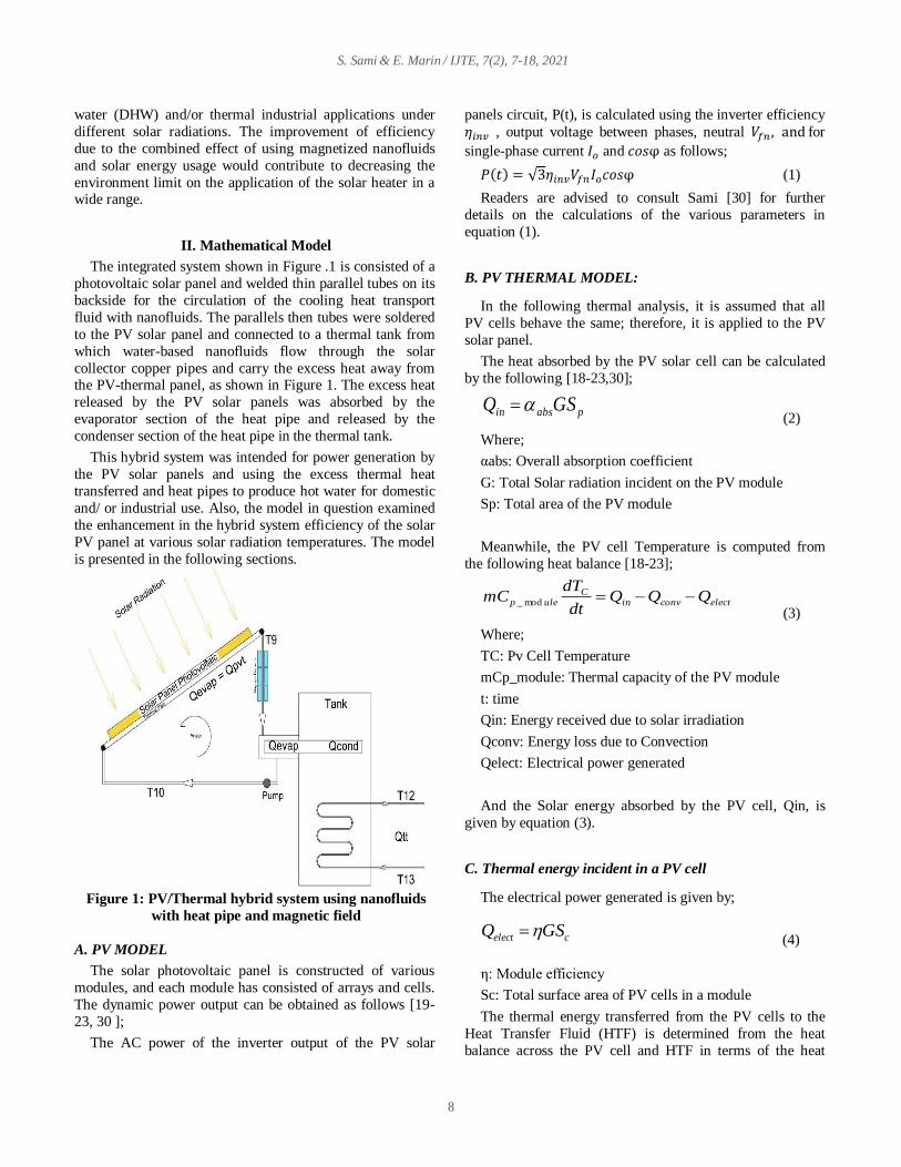
The integrated system shown in Figure .1 is consisted of a
photovoltaic solar panel and welded thin parallel tubes on its
backside for the circulation of the cooling heat transport
fluid with nanofluids. The parallels then tubes were soldered
to the PV solar panel and connected to a thermal tank from
which water-based nanofluids flow through the solar
collector copper pipes and carry the excess heat away from the PV-thermal panel, as shown in Figure 1. The excess heat
released by the PV solar panels was absorbed by the
evaporator section of the heat pipe and released by the
condenser section of the heat pipe in the thermal tank.
This hybrid system was intended for power generation by
the PV solar panels and using the excess thermal heat
transferred and heat pipes to produce hot water for domestic
and/ or industrial use. Also, the model in question examined
the enhancement in the hybrid system efficiency of the solar
PV panel at various solar radiation temperatures. The model
is presented in the following sections.
Figure 1: PV/Thermal hybrid system using nanofluids
with heat pipe and magnetic field
A. PV MODEL
The solar photovoltaic panel is constructed of various
modules, and each module has consisted of arrays and cells.
The dynamic power output can be obtained as follows [19-
23, 30 ];
The AC power of the inverter output of the PV solar
panels circuit, P(t), is calculated using the inverter efficiency
𝜂𝑖𝑛𝑣 , output voltage between phases, neutral 𝑉𝑓𝑛 , and for
single-phase current 𝐼𝑜 and 𝑐𝑜𝑠φ as follows;
𝑃(𝑡) = √3𝜂𝑖𝑛𝑣𝑉𝑓𝑛𝐼𝑜𝑐𝑜𝑠φ (1)
Readers are advised to consult Sami [30] for further
details on the calculations of the various parameters in
equation (1).
B. PV THERMAL MODEL:
In the following thermal analysis, it is assumed that all
PV cells behave the same; therefore, it is applied to the PV
solar panel.
The heat absorbed by the PV solar cell can be calculated
by the following [18-23,30];
pabsin GSQ (2)
Where;
αabs: Overall absorption coefficient
G: Total Solar radiation incident on the PV module
Sp: Total area of the PV module
Meanwhile, the PV cell Temperature is computed from
the following heat balance [18-23];
electconvinC
ulep QQQdt
dTmC mod_
(3)
Where;
TC: Pv Cell Temperature
mCp_module: Thermal capacity of the PV module
t: time
Qin: Energy received due to solar irradiation
Qconv: Energy loss due to Convection
Qelect: Electrical power generated
And the Solar energy absorbed by the PV cell, Qin, is
given by equation (3).
C. Thermal energy incident in a PV cell
The electrical power generated is given by;
(4)
η: Module efficiency
Sc: Total surface area of PV cells in a module
The thermal energy transferred from the PV cells to the
Heat Transfer Fluid (HTF) is determined from the heat
balance across the PV cell and HTF in terms of the heat
celect GSQ

S. Sami & E. Marin / IJTE, 7(2), 7-18, 2021
9
transfer mechanisms; conduction, convection, and radiation
as follows [1,17 through 23];
To close the energy balance in the equation (4), the heat
transfer by convection and by radiation are determined
respectively using the convection heat transfer coefficient
and emissivity PV cell Stefan-Boltzmann constant.
Interested readers in the calculation of the heat balance in
the equation (7) are advised to consult Sami [23,30].
The finite-difference formulation was used to determine
the heat transfer fluid temperature as follows at each
element using the following equation. The heat transfer fluid
tube is divided into, nTE, elements;
(5)
t: time
Tf_in: Fluid temperature at the inlet and represents the
time step iteration
The thermal energy transferred from the PV cell to the
heat transfer fluid is obtained by;
𝑄𝑇ℎ𝑒𝑟𝑚𝑎𝑙 =ṁ)( _1_ InffHxwaterp TTTC
(6)
QThermal: Energy from the thermal process
TfHx+1: Fluid temperature at thermal element 1
The energy transferred to heat transfer fluid is calculated
by the integration of the aforementioned equations along the
length of each tube. In this analysis, the mainstream
temperature of the heat transfer fluid flow was considered as
the average temperature of the inlet and outlet of each finite-
difference element;
inQṁw
)( 1_ ffwaterp TTC (7)
ṁw : Water flow.
Tf+1: Water temperature at the next element.
Cp: Specific heat of HTF.
Finally, the hybrid system PV-thermal energy conversion
efficiency for harnessing energy from solar radiation is
given;
𝜂𝑆𝐻 =𝑃(𝑡)+𝑄𝑡ℎ𝑒𝑟𝑚𝑎𝑙
𝑄𝑖𝑛
(8)
Where Qthand Qin is the solar thermal heat transferred to
the HTF and solar irradiance, the respective values are given
by equations (1) and (8), respectively. Besides, 𝑃(𝑡) Is the
PV solar electrical output and defined by equation (2).
D. Nanofluid heat transfer Fluid
The basic heat transfer fluid in the PV-Thermal loop, as
shown in Figure.1, is water-based nanofluids. Nanofluids
have been added to the water-based flow to enhance their
thermal properties. References [14-34] presented equations
to calculate the thermophysical and thermodynamic
properties of nanofluids such as specific heat, thermal
conductivity, viscosity, and density employing the law of
mixtures, as a function of the volumetric concentration of nanoparticles;
α total = α particles + α base fluid (9)
Where α represents a particular thermophysical property
of the nanofluid under investigation.
The nanofluid thermal and thermophysical properties,
αtotal, can be calculated as follows;
α total = α base fluid + αparticles.(Φ) (10)
Where; Φ represents the nanoparticles' volumetric
concentration.
E. Thermophysical Properties with Magnetic Field
The field-dependent thermal conductivity of magnetorheological fluids plays an important role in heat
transfer and dissipation in potential new applications.
Magnetic nanofluids with a low concentration of
nanoparticles can significantly enhance their thermal. This
research considers that magnetic metallic solids under
different magnetic forces Gauss improve thermal and
thermophysical properties compared to those of fluids, and
nanofluids and exhibit significantly higher thermal
properties compared to conventional heat transfer fluids. In
the following, we present the formulas developed based
upon the magnetic data published in the literature properties [10 through 31]; was used to taking into account the impact
of the magnetic field as outlined in Table.1
Table.1: Thermophysical properties as a function of
magnetic field forces in Gauss[30]
Where “b” represents the nanofluid specific property, and
“a” is the magnetic field force in Gauss. Cpnf, Knf, and h are
the specific heat, thermal conductivity, and heat transfer
coefficients of nanofluids.
Equation (10) can be used to determine other
thermophysical properties such as; α is the thermal
diffusivity, ʎ and ρ represent the thermal conductivity and
density as a function of the properties outlined in the Table.1
Ai203 CuO Fe304 SiO2
Cp
nf
b = 0.1042a
+ 6226.5
b = 0.2011a
+ 5730.8
b = 0.8318a +
4269.8
b = 0.6187a
+ 4293.2
K
nf
b = 2E-05a
+ 1.4888
b = 5E-05a
+ 1.3703
b = 0.0002a +
1.0209
b = 0.0001a
+ 1.0265
h b = 0.0031a
+ 73.092
b = 0.0031a
+ 73.073
b = 0.003a +
73.225
b = 0.003a
+ 73.231
tCm
QTT
pwater
inff
_
S. Sami & E. Marin / IJTE, 7(2), 7-18, 2021
10
F. Heat Pipe Model
For the heat pipe to work properly, the pressure drop in
the fluid flow embedded in the heat pipe has to be
compensated by the pumping pressure in the wick and the
capillarity as prescribed by Sami [16, 31], Tardy, and Sami
[33], Endalew [19], and Reay and Kew [32];
∆𝑃𝑝 = ∆𝑃𝑖 + ∆𝑃𝑣 + ∆𝑃𝑔 (11)
Where ∆Pp, ∆Pl, ∆Pv, and ∆Pg are the total pumping
pressure, pressure drop for liquid return from the condenser,
pressure drop for vapor flow in the evaporator, and gravity head, respectively.
The heat transfer limit for a heat pipe depends on the
construction of the heat pipe and the operating environment.
the design of the heat pipe and the wick properties are
determined by the thermophysical properties of the working
fluid used [30,32].“The heat pipe heat transfer capillary, sonic, entrainment, boiling, frozen start-up, continuum
vapor, vapor pressure, and condenser effects determine the
physical phenomena that establish the lowest limit of these
phenomena and are considered as a design limit”.[30,32]
The energy conversion and efficiency of heat transfer
from the evaporator section of the heat pipe to the condenser
section in the solar application becomes one of the important
selection criteria for the working fluid. Hence, the use of
working fluid with higher latent heat is very beneficial to the
applications of the heat pipes in solar energy conversion.
Water and different refrigerants such as R-134a, R-123, R-
32, R-125, R-152a, R-1234ze, and R-1234fz, as well as
refrigerant mixtures Sami [30,38], are considered in this
investigation as working fluids inside heat pipe.
The energy balance under natural convection heat transfer
condition in the thermal storage tank as per Figure .1, using
a single-control volume of heat pipe submerged in the
thermal tank is presented in the following equation), [13, 16,
30];
𝑉𝑤𝑃𝑤𝐶𝑤𝑑𝑇𝑤
𝑑𝑡= 𝜋𝑑𝑜𝐼𝑐𝑜𝑛𝑑ℎ𝑒𝑓𝑓(𝑇ℎ𝑝 − 𝑇𝑤) −
𝑈tan𝐴𝑡𝑎𝑛(𝑇ℎ𝑝 − 𝑇𝑎) (12)
Where Vw represents the water volume in the thermal
tank and Utan and Atan are the overall heat transfer
coefficient in the thermal tank and the equivalent heat
transfer area in the tank, respectively. Besides, Thp, Tw, Ta
are the temperatures of the heat pipe, water, and ambient air.
To determine the heat capacity of the condenser section of
the heat pipes, the following energy and mass balance
equations are considered;
𝑄𝑐𝑜𝑛𝑑 ℎ𝑝= 𝐻𝑒𝑓𝑓 ∗ (𝑇ℎ𝑝 − 𝑇𝑤) ∗ 𝑑𝑜 ∗ 𝐼𝑜 ∗ 𝜋 (13)
Where Io is the length of the condenser section of the heat
pipe.
On the other hand, the thermal energy dissipated into the
thermal tank from the heat pipes and delivered for the
domestic or industrial end-user is;
𝑄𝑡𝑡 = 𝜂ℎ𝑥 ∗ 𝑚𝑤𝑄𝑡𝑡∗ 𝐶𝑝𝑤
∗ (𝑇12 − 𝑇13) (14)
Where the 𝑚𝑤𝑄𝑡𝑡 Represents the water mass flow rate
circulating between the thermal tank and the user application
in question. T12 and T13 are the supply and return
temperatures from the end-user application, respectively. ηhx is the thermal tank efficiency.
The efficiency of the solar PV panels can be expressed as
follows;
𝜂𝑝𝑣 =𝑄𝑒𝑙𝑒𝑐
𝑄𝑐𝑜𝑙𝑙𝑒𝑐𝑡𝑜𝑟 (15)
Where Qelec is calculated by equation (1) and Qcollector
is obtained by equation (2).
The thermal efficiency of the heat pipe can be obtained by
the following equation;
𝜂ℎ𝑝 =𝑄𝑐𝑜𝑛𝑑ℎ𝑝
𝑄𝑐𝑜𝑛𝑑ℎ𝑝
(16)
Where, 𝑄𝑐𝑜𝑛𝑑 ℎ𝑝represents the heat released by the
condenser section of the heat pipe
Finally, the hybrid system energy conversion efficiency
for harnessing energy from solar energy using the thermal
panels and heat pipe can be formulated as;
𝜂𝑠ℎ =𝑄𝑒𝑣𝑎𝑝ℎ𝑝
+𝑄𝑒𝑙𝑒𝑐
𝑄𝑐𝑜𝑙𝑙𝑒𝑐𝑡𝑜𝑟 (17)
Where Qelec is calculated by equation (1)
III. Numerical Procedure
The energy conversion equations and heat transfer
mechanisms of nanofluids under the magnetic field force
taking place during various processes PV-Thermal shown in
Figures.1 and were outlined in the model presented in
Equations (1) through (17).
The aforementioned energy conversion equations have
been solved as per the logical flow diagram presented in
Figure 2, where, the input parameters of the solar PV
conditions such as solar radiation, ambient temperature, and
humidity as well as other independent parameters such as nanofluids and magnetic filed force are defined. The
dependent parameters were calculated and integrated into the
system of finite-difference formulations developed after the
energy conservation equations under nanofluids and
magnetic fields. Iterations were performed until a converged
solution was reached with an acceptable iteration error.
The numerical procedure as per Figure .2 started by using
the solar radiation, ambient conditions to calculate the solar

S. Sami & E. Marin / IJTE, 7(2), 7-18, 2021
11
PV cell temperature, and PV cell back the temperature as
well as the heat transfer fluid mass flow rate circulating in
the thermal closed-loop using nanofluids and under
magnetic field at specified conditions. The thermodynamic
and thermophysical properties of Heat Transfer Fluid were employed to calculate the water-based nanofluids flow rate.
This was followed by using the finite-difference
formulations to predict the time variation characteristics of
the PV cell temperature, the PV back temperature, and
thermal heat transferred to the Heat Transfer Fluid, Heat
transfer fluid outlet temperature at the heat exchanger, as
well as other hybrid system power outputs and efficiencies.
Finally, hybrid system efficiency was calculated at each
input condition of nanofluids, concentrations, and magnetic
field force.
IV. Results and Discussion
Equations (1) through (17) representing the present
numerical model have been solved, taking into account the
heat and mass transfer mechanisms during the solar PV-
Thermal energy conversion process under different solar
radiations, magnetic field forces, and nanofluids. The above-
mentioned equations were coded with finite-difference formulations and solved as per the logical flow chart
depicted in Figure.2. Besides, the predicted simulated results
for PV-Thermal solar panels were compared to the data
published in the literature under various conditions.
In the following sections, we present analysis and
discussions of the numerical results predicted as well as validations of the proposed simulation model. The
simulations were performed at different temperature
differences across the thermal tubes of the heat exchanger
welded beneath the PV solar panels; however, only results
will be presented and analyzed for the temperature
difference of 15 °C across the thermal tube. It is worthwhile
noting that the numerical simulation presented hereby was
conducted under different conditions such as; PV cell
temperatures from 10°C through 38°C, ambient
temperatures from 10°C through 38°C, solar radiations; 500,
750, 1000, and 1200 w/m2, different nanofluids; A2O3,
FE304, SiO2, CuO at various concentrations; 5,10 and 20% and under a magnetic force that varied from 127 Gauss up to
3000 Guass.
The PV panel characteristics under consideration in this
study were obtained from Fargali et al. [34]. The parameters
adopted in this study were; Total surface area of the PV module (SP) is 0.617 m2, Total surface area of cells in
module (Sc) is 0.5625 m2, module efficiency 12% at
reference temperature ( 298 K), the overall absorption
coefficient is 0.73, and Temperature coefficient is 0.0045 K-
1. Interested readers in the full range values of the other
parameters are advised to consult Fargali et al. [34] and
Sami [30].
Figure.2 Logical flow diagram
It was also assumed in this simulation that the whole
panel was covered in PV cells, with no packing material (the
material used to fill in gaps between the cells on a panel. The
PV cells are commercial grade monocrystalline silicon cells
with an electrical efficiency of 12% and have a thermal
coefficient, of 0.54% [1/K] Sami [30].
As per the equations outlined above, and results presented
in Figure .3, the increase in the PV cell temperature due to
solar radiation resulted in an increase in the back cell
temperature and consequently the heat transport water-based
fluid temperature due to the heat transfer from solar energy
by conduction and convection as well as radiation,
respectively. It has been demonstrated by Sami [30] that the
higher the cell temperature, the higher the back cell and heat
transport water-based fluid temperatures, and the higher the
solar radiations, the higher the energy absorbed by the PV
cell, and consequently the higher the temperature of the cell until reaches the design temperature. For further details,
interested readers are advised to consult Sami [30]
The effects of the PV panel operating temperature on the
output efficiency have been well documented in the
literature [14 through 30], where the increasing temperature of the PV cell decreased the amount of power available.
However, it is important to note that the changes in the PV
cell temperature caused by solar radiation have a dynamic
nature. The PV panel heats up and cools down gradually
depending upon the changes in solar radiation in dynamic
response and consequently the power output from the PV

S. Sami & E. Marin / IJTE, 7(2), 7-18, 2021
12
panel. It was quite evident from the results reported in the
literature, namely Sami [30] and others presented in Figure
.3, that the cell temperatures, as well as the other ones,
increase with the increase of solar radiation. This can be
interpreted as per equations (1) through (3), where the dynamic cell temperatures are expressed in terms of the heat
balance across the PV cells.
Figure.3 Cell temperatures at different solar radiations
Figure.4 Heat transport fluid temperature at different
solar radiations.
Figure.5 Water mass flow rate at different solar
radiations and heat exchanger temperature difference 15
°C.
The results presented in Figures.4 and 5showed that the
higher the solar radiation, the higher the thermal energy
absorbed, and the longer the time, the slightly the mass flow
rate of the heat transport water-based fluid is reduced. The
results also showed, as expected the heat transport fluid
mass flow rate increased at higher solar radiation as well as
the heat transport fluid temperatures. This is because the
higher solar radiation resulted in higher thermal energy
transferred to the fluid flow, and consequently, this increased the heat transport temperatures and the fluid flow
mass flow rate.
Figure.6 Thermal energy generated at PV-Th solar
panels
Nanofluid Ai2O3 has been reported the most and studies
in the literature for comparison purposes. Figures .6and 7 were constructed to analyze the different parameters of the
thermal energy converted and transferred to the nanofluid
Ai2O3 heat transport fluid at different temperatures and
concentrations %5, circulating beneath the PV-Th solar
panel under solar radiation of 750 w/m2 and at different
magnetic fields forces. Also, as it can be observed, the
higher the magnetic field, the higher the thermal energy
dissipated from the heat pipe at the condenser side into the
storage tank.
The heat pipe condenser section’s thermal energy
calculated by equation (13) has been plotted in Figure .7 at
different heat pipe temperatures. This thermal energy was
transferred from the evaporator section of the heat pipes
through the heat pipe filled in working fluid and appeared to
show that its dependence upon the magnetic field; however,
the higher the heat pipe temperature, the higher the heat pipe
condenser section’s heat dissipated into the thermal storage tank. As discussed in Sami [30], the thermal energy
transferred to the nanofluid heat transfer fluid increased the
heat transport fluid flow rate and the heat pipe temperature;
thus, it can be concluded that the magnetic field indirectly
impacted the thermal heat developed at the heat pipe
condenser section.
The hybrid thermal efficiency of the proposed system, as
defined in equation (17), was determined as thermal energy
and electrical power generated divided by the solar radiation
absorbed by the PV solar panel. Also, the heat pipe
efficiency has been calculated by equation (16), It is quite
evident from the results presented in Figures.8, and 9 that
the higher the magnetic field, the higher the hybrid thermal
conversion efficiency and the higher the heat pipe efficiency.

S. Sami & E. Marin / IJTE, 7(2), 7-18, 2021
13
The results in these figures also demonstrated that the higher
the magnetic field, the higher the nanofluid heat transport
temperatures, and the higher thermal energy transferred to
the heat transport nanofluid. Further, Figures8 and 9 confirm
that the higher the magnetic field, the higher the heat dissipated from the heat pipe condenser and the higher the
heat pipe efficiency.
Figure.7 Thermal energy at heat pipe condenser
generated by PV-Th solar panels
Figure.8 Thermal efficiency of heat pipe evaporator
generated by PV-Th solar panels
Figure.9 Thermal efficiency of hybrid system generated
by PV-Th solar panels
Figure.10 Thermal energy of hybrid system generated by
PV-Th solar panels
The effect of solar radiations on the PV-Th integrated
heat pipe loop was demonstrated in Figures 10 through 13,
for nanofluid Ai2O3 at a specific concentration where the key parameters of the PV-Th hybridimpacting the heat pipe
behavior such as thermal energy transferred from PV-Th
solar panels, the efficiency of the hybrid system, and heat
pipe efficiency were displayed at solar radiations of 500,
750, 1000 and 1200 W/m2. The results in the
aforementioned figures showed that the higher the solar
radiation, the higher the thermal energy transferred to the
nanofluid loop feeding the heat pipe evaporator section. In
turn, this thermal energy was enhanced at higher solar
radiation that results in the enhancement of the heat
developed at the heat pipe condenser section and consequently increased the heat pipe efficiency
Figure.11 Thermal efficiency of hybrid system generated
by PV-Th solar panels
Figure.12 Thermal energy developed at heat pipe
condenser generated by PV-Th solar panels

S. Sami & E. Marin / IJTE, 7(2), 7-18, 2021
14
Figure.13 Thermal efficiency of heat pipe generated by
PV-Th solar panels
Figure.14 Thermal energy at the condenser of heat pipe
generated by PV-Th solar panels
Figure.15 Thermal efficiency of heat pipe generated by
PV-Th solar panels
As reported in References [1-14-,30, 34], the
thermophysical and thermodynamic properties of nanofluids
such as specific heat, thermal conductivity, viscosity, and
density employing the law of mixtures, as a function of the
volumetric concentration of nanoparticles; equations (9) and
(10) significantly influence the characteristics of nanofluids at the different magnetic fields and in particular the behavior
of heat pipes. In particular, Figures 14 and 15 have been
constructed to illustrate that the higher the nanofluid
concentrations, the higher the thermal performance. This
was due to higher concentrations of nanofluid enhanced the
thermophysical properties of the heat transport fluid, heat
transfer coefficient, and the thermal energy transferred. As
seen in these figures, higher thermal energy dissipated at the
heat condenser side, and the efficiency of the heat pipe occur
at higher nanofluid concentration; however, higher
concentrations induce higher fluid friction and pressure drop in the hybrid system that have negative effects on the system
performance and its hybrid efficiency. . Similar observations
were noted regarding the other main key parameters of the
heat pipe and hybrid system in questions at the different
nanofluids. Therefore, it is paramount for the designer to
strike a balance between heat pipe performance and the
chosen nanofluid concentration to achieve the best and
optimize the hybrid system performance
It is also believed that the enhancement of characteristics
of the nanofluids was caused by the increase in thermal
conductivity of the magnetic nanofluids and can be
explained by the interaction among the dispersed
nanoparticles and how their behavior changes in the
presence of a magnetic field. The phenomenon of
enhancement of thermal conductivity can be explained based
on chain formation due to particle-particle interactions and
alignment along the magnetic field [18 through 27] and Sami [30]), which resulted in the formation, conducting, and
diffusing of thermal energy.
Another angle of this study is to study the impact of using
different nanofluids. During this investigation, we observed
that the nanofluid concentrations have a significant effect on
the system's main characteristics, such as the thermal energy transferred to the nanofluid heat transport fluid, thermal
energy released by the heat pipe condenser, heat-pipe
efficiency, and the hybrid system thermal efficiency. The
results displayed in these figures demonstrated that the CuO
exhibits superior characteristics over the other nanofluids
presented in figures; 16 through 18, Ai2O3, Fe304, and
SiO2; thus, the use of nanofluidCuO resulted in higher
performance of the above-mentioned parameters compared
to the other heat transport fluids including the water base.
Because the nanofluidCuO has higher thermodynamic and
thermophysical properties higher than the other nanofluids
under investigation, including the water as heat transport fluid. It was also observed that the higher the nanofluid
concentrations, the higher the thermal performance and, in
particular, the heat pipe efficiency. Also, Figures 16 through
19indicated that the higher the Gauss magnetic intensity, the
higher the thermal performance of the hybrid system and
thermal energy released by the condenser section of the heat
pipe.
As reported by reference [27-30, 36], the increase in
thermal conductivity under an external magnetic field is
attributed to the effective conduction of heat through the
chainlike structures[47] through [50]. Figure .19 gave a
piece of clear evidence that the heat pipe thermal efficiency
has been enhanced at higher CuO concentrations compared
to the water-based heat transport fluid, which was caused by
the increase of thermal conductivity of the heat transport

S. Sami & E. Marin / IJTE, 7(2), 7-18, 2021
15
fluid as discussed earlier in the paper. Readers interested in
this subject matter are advised to consult these references
[27-30, 36, 47-50}.
Figure.16 Thermal efficiency of hybrid system generated
by PV-Th solar panels with different nanofluids
Figure.17 Thermal energy released by heat pipe
condenser generated by PV-Th solar panels with
different nanofluids
Figure.18 Thermal efficiency of heat pipe generated by
PV-Th solar panels with different nanofluids
V. Model validation
The numerical results predicted by the model described
above have been validated with data presented in the
literature for solar PV, namely references [34,30, 56]. In
particular, it is quite apparent from the comparison presented
in Figure. 20that the model prediction fairly compares with
the data of the dynamic PV cell temperature presented by Fargali et al. data [34], also showed that the model and data
have the same trend; however, some discrepancies exist. The
discrepancies are becauseFargali et al. [34, 56] did not
provide full disclosure of the various parameters used.
The thermal energy was calculated under a magnetic field
has been compared to experimental data on the magnetic
field, and nanofluids were scared and hardly reported in the
literature. The data reported by references[49-51] on
nanofluid Fe304 were considered and compared at the
different magnetic fields up to 7000 Gauss and at a
temperature difference of 15 C. The nanofluid Fe304, the
choice for his study, was found to be the nanofluid with a
0.1% volume concentration. The results of our model prediction were compared to the data of references [49-51]
at similar conditions and plotted in Figure. 20. The
comparison showed discrepancy exited and varied between
8% to 14% with the model over predicting the experimental
data.
Figure.19 Thermal efficiency of heat pipe generated by
PV-Th solar panels with different nanofluids
VI. Conclusions
The energy conversion equations describing the mass and
energy balances of a novel combined concept of a
photovoltaic-thermal solar panel integrated heat pipe hybrid
system has been developed, integrated, and solved to predict
the total dynamic power generated, efficiencies of the hybrid
system and heat pipe, and the important key parameters
under different solar irradiance, using nanofluids; Ai2O3,
Cuo, Fe304, SiO2, and Cuoand different magnetic field
forces. The model was based on dynamic mass and energy
equations coupled with the heat transfer coefficients,
thermophysical properties of magnetized nanofluids,
thermodynamic constants, and as well as other material properties.
It is evident from the results presented in this paper that
the higher the solar radiations, the higher the thermal and the
higher the hybrid system efficiencies and also the higher the
heat pipe efficiency and heat released by the condenser.
Furthermore, the PV simulation study results showed that the higher the solar radiation, the accelerated increase in the
PV cell temperature. Consequently, it also shows the higher
the solar radiation, the higher the PV cell temperatures,
power, and PV amperage. As far as the simulation of PV-Th,
it was demonstrated that the higher the nanofluids

S. Sami & E. Marin / IJTE, 7(2), 7-18, 2021
16
concentration, the higher the hybrid system characteristics
and the higher the heat released at the heat pipe condenser
section and efficiency. Besides, the higher, the magnetic
field, the higher the thermal energy and the hybrid system
efficiency and heat pipe efficiency. Finally, it was shown that the nanofluidCuOexhibited the highest hybrid system
characteristics and heat pipe performance compared to the
other nanofluids including water-based fluid.,under
consideration.
The designer of the PV-Th solar panel integrated heat
pipe hybrid system must take into consideration the solar radiation, type of nanofluid as well as ambient conditions.
Finally, the model prediction was compared fairly with the
PV-Thermal data available in the literature on magnetized
nanofluids at different conditions of solar radiations,
nanofluid concentrations, and magnetic field forces.
Figure 20. Comparison between present model prediction
for cell temperature and Fargali et al. data [34].
Figure 21. Comparison between present model and data
for Nanofluid Fe 304 data at different magnetic fields
[49].
VII. Nomenclature
Cp_water Thermal capacity of water (J/kgK)
D Internal Pipe diameter (m)
G Total Solar radiation incident on the Pv module
(W/m2)
H Convective heat transfer coefficient module
(W/m2K)
hwater Heat transfer coefficient (W/m2K)
IOutput current of the Pv module (A)
ṁ Water flow (Kg/s) mCp_moduleThermal capacity of the Pv module
mwater mass of water (Kg)
Npipes Number of pipes
Ns Total number of cells connected in series
nTE number of Thermal Elements in a pipe
P Power generated by Pv module (W)
Pa Atmospheric pressure of moist air (Pa) pw Partial pressure of water vapor in moist air (Pa)
QconductionEnergy due to conduction
(W in Electrical Process)
(W/m2 in Thermal Process)
QconvectionEnergy due to convection
(W in Electrical Process)
(W/m2 in Thermal Process)
Qelect Electrical power generated (W)
Qin Energy received due to Solar irradiation (W/m2)
Qin_cell Energy incident on one Pv cell due to solar radiation
(W/m2)
Qradiation Energy due to radiation (W/m2 in Thermal Process) QThermal Energy from thermal process (W)
Sc Total surface area of Pv cells in a module (m2)
Sp Total area of the PV module (m2)
T Operating temperature (k)
T Time (s)
Ta Ambient temperature (°C)
TC Pv Cell Temperature (°C)
Tdb Dry bulb temperature (°C)
Tf Fluid temperature (°C)
Tf Fluid temperature (°C)
Tf_in Fluid temperature at the inlet (°C) TfHxMaximum temperature at the Heat Exchanger
(°C)
TfHx+1Fluid temperature at thermal element 1 (dx) (°C)
Tm Module Back-surface temperature (°C)
Tr Nominal temperature (298.15 K)
U Thermal conductance of clean heat exchanger
(W/m2K)
UdThermal conductance of heat exchanger after
fouling (W/m2K)
V Output voltage (V)
αabs Overall absorption coefficient ηHybrid Hybrid system efficiency
ηPvPV module efficiency
ηThermal Efficiency of thermal process
ρwDensity of water vapor (Kg/m3)
Q Convection heat transfer rate
Emissivity PV cell

S. Sami & E. Marin / IJTE, 7(2), 7-18, 2021
17
ACKNOWLEDGMENT
The research work presented in this paper was made
possible through the support of the Catholic University of
Cuenca and the Research Center for Renewable Energy. The
authors are all technical assistants for their hard work in
executing the numerical work.
VIII. REFERENCES
[1] S. Sami, Modelling and Simulation of Performance of Nanofluids in
PV-Thermal Solar Panel Collectors, RA JOURNAL OF APPLIED
RESEARCH, ISSN: 2394-6709 (Online), DOI:
https://doi.org/10.31142/rajar/v5i1.07.,(2019).
[2] S. Akilu, K. V. Sharma, A. T. Baheta, and R. Mamat, A review of
thermophysical properties of water-based composite nanofluids.,
Renew. Sustain. Energy Rev., 66 (2016) 654–678,
doi:10.1016/j.rser.2016.08.036.
[3] P.K. Nagarajan, J. Subramani, S. Suyambazhahan, R. SathyamurthY.,
Nanofluids for solar collector applications: A Review, Energy
Procedia 61 (2014) 2416 – 2434.
[4] S. Sami., Analysis of Nanofluids Behavior in a PV-Thermal-Driven
Organic Rankine Cycle with cooling Capability, Appl. Syst. Innov.
(2020) 3, 12; doi:10.3390/asi3010012 www.mdpi.com/journal/asi,
[5] Sagadevan, S., (2015) A review of the role of Nanofluids for Solar
Energy Applications, American Journal of Nano Research and
Applications, 3(3) (2015) 53-61.
[6] Chaudhari, K, S, and Walke, P.V., Applications of NanoFluid in Solar
Energy- A Review, International Journal of Engineering Research &
Technology, IJERT, 3(3) (2014) 460-463.
[7] Kaseian, A, Eshghi, A. T. and Sameti, (2015) A Review on the
Applications of Nanofluids in Solar Energy Systems, Renewable, and
Sustainable Energy Reviews, 43( 2015) 584-598.
[8] O. Mahaian, A. Kianifar, S.A. Kaliogirou, I. Pop, S. Wongwises, A
review of the applications of nanofluids in solar energy, International
Journal of Heat and Mass Transfer 57 (2013) 582–594.
[9] R. Gangadevi, ShobhitAgarwal, and Shirsho Roy, A Novel Hybrid
Solar System Using Nanofluid, International Journal of Engineering
Research and Technology. ISSN 0974-3154 6(6) (2013) 747-752.
[10] S.Sami and F. Quito, (2019), Experimental and Numerical Study of
Magnetic Field Impact on the Thermal Solar Collectors»,
International Journal of Sustainable Energy and Environmental
Research, IJEER, 8(1) (2019) 10-28 ISSN(e): 2306-6253ISSN 2312-
5764 DOI: 10.18488/journal.13.2019.81.10.28.
[11] Cem L. Altan, AlperElkatmis, MerveYusel, NecdetAslan, and
SeydaBucak, Enhancement of thermal conductivity upon application
of magnetic field to Fe3O4 nanofluids, Journal of Applied Physics
110, 093917 (2011).
[12] Abdulhassan A. Karamallah, LaithJaaferHabeeb, and Ali Habeeb
Asker, The Effect of Magnetic Field with Nanofluid on Heat Transfer
in a Horizontal Pipe, Al-Khwarizmi Engineering Journal, 12(3)
(2016)99- 109.
[13] Yu Wang., Experimental study on the effect of magnetic fields on
heat transfer performance of nanofluid heat pipe, South China
Agricultural University, DOI:10.1109/CECNET.2011.5769054.,
(2011).
[14] S. ValiallahMousavi M., SheikholeslamiMofid, Gorji bandy,
M.BarzegarGerdroodbary, ( 2016), The Influence of magnetic field
on heat transfer of a magnetic nanofluid in a sinusoidal double pipe
heat exchanger, Chemical Engineering Research and Design, 113
(2016) 112-124
[15] Do, H., Ha, K. H.J., and Jang, S.P., Thermal Resistance Of
Screen Mesh Wick Heat Pipe Using The Water-based
Al2O3Nanofluids., International Journal of Heat and Mass
Transfer, 25, 5888-
5894.http://dx.doi.org/10.1016/j.ijheatmasstransfer.2010.07.050
(2010).
www.mdpi.com/journal/nanomaterials,
[16] Yang, X.F., Liu, Z.H., and Zhao, J., Heat Transfer Performance of A
Horizontal Micro grooved Heat Pipe Using CuONanofluids., J
MicromechMicroeng, 18,035038.http://dx.doi.org/10.1088/0960-
1317/18/3/035038 (2008).
[17] Kang, S.W., Wei, W.C., Tsai, S.H., and Yang, S.Y., Experimental
Investigation of Silver Nano-fluid on Heat Pipe Thermal
Performance, Applied Thermal Engineering. 26 (2006) 2377–
2382.http://dx.doi.org/10.1016/j.applthermaleng.2006.02.020.
[18] Giwa, S.O., Sharifpur, M., Ahmadi, M.H. et al., A review of magnetic
field influence on natural convection heat transfer performance of
nanofluids in square cavities. J Therm Anal Calorim (2020).
https://doi.org/10.1007/s10973-020-09832-3
[19] Chiang, YC.,Chieh, JJ. & Ho, CC., The magnetic-nanofluid heat pipe
with superior thermal properties through magnetic enhancement.
Nanoscale Res Lett 7, 322(2012). https://doi.org/10.1186/1556-276X-
7-322, 2012
[20] WANG Xin-hua and JIAO Yu-lin, Study on the Heat Transfer
Characteristic of Heat Pipe Containing Magnetic Nano-Fluids
Strengthened by Magnetic Field, Mathematical Modelling of
Engineering Problems, 2(1) (2015) 5-8
http://dx.doi.org/10.18280/mmep.020102
[21] Allen, C., Magnetic Field Enhancement Thermal Conductivity
Analysis of Magnetic Nanofluids, MScE, the University of Texas at
Arlington, (2015).
[22] Ajay Katiyara, PurbarunDharb, TandraNandic,Sarit K. Dasb,
Magnetic field-induced augmented thermal conduction phenomenon
in magneto nanocolloids, School of Mechanical, Materials, and
Energy Engineering (SMMEE), Indian Institute of Technology Ropar,
Rupnagar–140001, India,(2015).
[23] M. S. A. Rahim, I. Ismail, Review of magnetorheological fluids and
nanofluids thermal behavior, Faculty of Manufacturing Engineering,
Universiti Malaysia Pahang,26600 Pekan, Pahang, Malaysia, IOP
Conf. Ser.: Mater. Sci. Eng.100 01204, 2015 3rd International
Conference of Mechanical Engineering Research (ICMER
2015)IOPPublishingIOP Conf. Series: Materials Science and
Engineering100(2015) 012040 doi:10.1088/1757-
899X/100/1/012040(2015).
[24] Sheikoleslami M., Zia Q.M.Z., Ellahi R., Influence of Induced
Magnetic Field on Free Convection of Nanofluid Considering Koo-
Kleinstreuer-Li (KKL) Correlation, Appl. Sci., 6(11) (2016) 324
[25] Soltanipour, H., Gharegöz, A. &Oskooee, M.B. Numerical study of
magnetic field effect on the ferrofluid forced convection and entropy
generation in a curved pipe. J Braz. Soc. Mech. Sci. Eng. 42 (2020)
135. https://doi.org/10.1007/s40430-020-2218-5
[26] Dheyaa A. Khalaf,Karima E. Amori,FirasM.Tuaimah, Effect of
Electromagnetic Field on the Natural Circulation in Solar Absorber
Tube: Review PaperJournal of Mechanics of Continua and
Mathematical Science,15(6)
(2020)https://doi.org/10.26782/jmcms.2020.06.00002
[27] SerkanDoganay, RahimeAlsanğur and AlpaslanTurgut, Effect of
external magnetic field on thermal conductivity and viscosity of
magnetic nanofluids: a review, September 2019Materials Research
Express 6(11) (2019) DOI: 10.1088/2053-1591/ab44e9
[28] Lucian Pîslaru-Dănescu, Gabriela Telipan, Floriana D. Stoian,
SorinHolotescu, andOana Maria Marinică, (2000), Nanofluid with
Colloidal Magnetic Fe3O4 Nanoparticles and Its Applications in
Electrical Engineering, Chapter 8, http://dx.doi.org/10.5772/65556
[29] Sami, S., (2017), Enhancement of Performance of Thermal Solar
Collectors Using Nanofluids. International Journal of Energy and
Power Engineering, Special Issue: Green Hybrid Systems for Power
Generation in Remote Zones Non-Connected to Grid, 7(1)(2018) 1-8.
DOI: 10.11648/j.ijepe.s.2018070101.11, 2017.
[30] S. Sami,(2021). Impact of Nanofluids on Performance of Solar
Photovoltaic-Thermal Panel and Heat Pipe Hybrid System. SSRG
International Journal of Thermal Engineering 7(1)(2019) 5-20
[31] Reay D.A., Kew P.A., Heat Pipes, 5th Edition, Butterworth-
Heinemann publisher, Oxford, UK(2006).

S. Sami & E. Marin / IJTE, 7(2), 7-18, 2021
18
[32] Tardy, F. and Sami, S., An Experimental Study Determining
Behaviour of Heat Pipes in Thermal Storage, International Journal of
Ambient Energy, 29(3) (2008).
[33] Tardy F., Sami S. M., Thermal analysis of heat pipes during thermal
storage. Applied Thermal Engineering, 29: 329–333,(2009).
[34] Fargali, H., M., Fahmy, F.H. and Hassan, M.A., A Simulation Model
for Predicting the Performance of PV/Wind- Powered Geothermal
Space Heating System in Egypt, The Online Journal on Electronics
and Electrical Engineering (OJEEE), 2(4) (2008).
[35] S.Sami and F. Quito., Experimental and Numerical Study of Magnetic
Field Impact on the Thermal Solar Collectors», International Journal
of Sustainable Energy and Environmental Research, IJEER, 8(1)
(2019) 10-28 ISSN(e): 2306-6253ISSN (p): 2312-5764 DOI:
10.18488/journal.13.2019.81.10.28, 2019.
[36] Hammad A Younes, Hammad A, Younes, Greg Christensen, Dong
Li, Amal A Al Ghaferi and Amal A Al Ghaferi Thermal Conductivity
of Nanofluids: Review, Journal of Nanofluids 4(2) (2015) DOI:
10.1166/jon.2015.1151, 2015.
[37] Yu Guangbin, GaoDejun, Chen Juhui, Dai Bing, Liu Di, Song Ye,1
and Chen Xi, Experimental Research on Heat Transfer
Characteristics of CuONanofluid in Adiabatic Condition, Journal of
Nanomaterials, Volume 2016, Article ID 3693249, 7(2016) pages
http://dx.doi.org/10.1155/2016/3693249
[38] Yildirim G, Genc S. Experimental study on heat transfer of the
magnetorheological fluids. Smart Materials and Structures. (2013)
22:1-8.
[39] Philip J, Shima P, Raj B., Evidence for enhanced thermal conduction
through percolating structures in nanofluids. Nanotechnology.,
(2008)19:305706.
[40] Khullar,V., Tyagi,H, Phelan, P.E, Qtanicar, T.,Singh, H. and Taylor,
R.A.(2013), Solar Energy Harvesting using Nanofluids-based
Concentrating Solar Collector, Journal of Nanotech Enf Med, 3(3)
(2013) 031003(9p).
[41] Taylor, R.A, Phelan, P.E, Qtanicar, T., Walker, C.A., Nguyen, M.,
Timble, S. and Prasher, R., Applicability of nanofluids in high Flux
Solar Collectors, Renew Sustain Energy, 3(2011) 0231104.
[42] Ghadi, A, Z and Valipour, M, S., Numerical Study of Hydro-
Magnetic Nanofluid Mixed Convection in a Square Lid-Driven
Cavity Heated from Top and Cooled from Bottom, Trans. Phenom.
Micro Scales, 2(1) (2014) 29-42.
[43] Nkurikiyuimfura, I, Wang, Y., Heat Transfer Enhancement by
Magnetic nonfluids- A Review, Renewable, and Sustainable Energy
Reviews, 21 (2013) 548-561.
[44] Nae-Huyn, K, 2005, Principales of Enhanced Heat Transfer, 2nd ed
Taylor & Francis, Routledge, (2005).
[45] Kuzubov, AO and Invanova, O L, 1994, Magnetic Liquids for Heat
Exchange, Journal de Physique III France.,4 (1994) 1-6.
[46] Khashan,S, Dagher,S, Al Omari,S., N Tit, Elnajjar, E, Mathew, B and
Hilal-Alnaqbi, A, (2017), Photo-thermal characteristics of water-
based Fe3O4@SiO2 nanofluid for Solar-Thermal Applications,
Materials Research Express, 4(5) (2017) 055701, 1-11.
[47] He, Q, Geni Y, and Shuangfeng W, (2016), Experimental
Investigation on Solar Thermal Properties of Magnetic Nanofluids for
Direct Absorption Solar Collector, ASME 2016 5th International
Conference on Micro/Nanoscale Heat and Mass Transfer, Biopolis,
Singapore, 1 (2016) 4–6.
[48] Katiyar, A, Dharn, P, Nandi, T and Das, S.K (2016), Magnetic Field
Induced Augmented Thermal Conduction Phenomenon in Magneto,
Journal of Magnetism and Magnetic Materials, 419(1) (2016) 588-
599.
[49] Hong, T-K, Choi, Yang, H-S, Choi, C J, Study of the Enhanced
Thermal Conductivity of Fe nanofluids, Journal of Applied Physics,
97 (2005) 064311, (2005).
[50] Cai R, Yang H W, He J S, and Zhu W P., The effects of magnetic
fields on water molecular hydrogen bonds. J MolStruc 938 (2009) 15-
19.
[51] Pang X F, Deng B, and Tang B O., Influences of magnetic field on
macroscopic properties of water. J Mod PhysLett B 26 (2012)
1250069-13.
[52] Sami, S., and Zatarain, J., Thermal Analysis and Modelling of
Thermal Storage in Solar Water Heating Systems, IJEPE,
International Journal of Energy and Power Engineering, 5(2)
(2016)48 - 59, 2016.
[53] Azo Material, http://www.azom.com/properties.aspx
[54] Wua, S., Wanga, S., Xiaoa, S., Zhub, D., (2012), Numerical
Simulation on Thermal Energy Storage Behavior of CU/paraffin
nanofluids PCMs, Energy Procedia, 31(2012) 240-244.
[55] Johannes Joubert., Influence of a magnetic field on magnetic
nanofluids to enhance natural convection heat transfer, MASTER of
engineering in the Department of Mechanical and Aeronautical
Engineering University of Pretoria (2017).
[56] Rajapakse, A, Chungpaibulpantana, S., Dynamic simulation of a
photovoltaic refrigeration system. RERIC 16(3) (1994) 67-101.