effect of the manufacturing process on the interfacial...
TRANSCRIPT

Effect of the manufacturing process on the interfacial properties
and structural performance of multi-functional composite structures
S. Mahdia, B.A. Gamaa,b, S. Yarlagaddaa, J.W. Gillespie Jr.a,b,c,*
aCenter for Composite Materials, University of Delaware, 201 Composites Manufacturing Laboratory, Newark, DE 19716-3144, USAbDepartment of Materials Science and Engineering, University of Delaware, Newark, DE 19716, USA
cDepartment of Civil and Environmental Engineering, University of Delaware, Newark, DE 19716, USA
Received 30 August 2002; revised 15 January 2003; accepted 7 March 2003
Abstract
A composite integral armor (CIA) structure consists of various layers such as ceramics, rubber and polymer composites assembled in a
precise sequence to provide superior ballistic and structural performance at low areal density. CIA structures were originally manufactured in
a labor-intensive multi-step process. In recent years, vacuum-assisted resin transfer molding (VARTM) has emerged as an affordable
manufacturing method for CIA structures. In this paper, the relationship between the manufacturing processes (i.e. VARTM and multi-step)
and the mechanical performance of CIA beams is investigated by four-point bend tests. The behavior of the CIA is found to be highly
dependent on the mechanism of stress transfer between the layers and the structures are found to fail progressively and provide significant
ductility and capacity. The VARTM process is found to produce structures with superior mechanical performance. Moreover, the level of
interface adhesion achieved during processing is shown to control the structural behavior of the CIA. Consequently, the Mode I fracture
testing of VARTM and multi-step manufactured double-cantilever beams, representative of one interface of the CIA, is characterized. The
resistance to crack growth of the specimens is also related to the manufacturing process, with the VARTM specimens achieving the highest
fracture toughness.
q 2003 Elsevier Science Ltd. All rights reserved.
Keywords: A. Layered structures; B. Strength; D. Mechanical testing; E. Injection moulding
1. Introduction
The US Army requires the development of lightweight
ground vehicle structures that must satisfy structural (i.e.
stiffness, strength, damage tolerance, fatigue and environ-
mental durability) and ballistic performance at minimum
weight. This need has led to the development of lightweight
ceramic-faced composite integral armors (CIA) [1–4]. A
CIA structure was initially developed by United Defense
(USA), as part of the Composite Armored Vehicle
Advanced Technology Demonstrator program. The CIA
considered in the present work consists of a polymer
composite cover layer, a layer of alumina ceramic tile,
a layer of rubber and a polymer composite backing plate, as
shown in Fig. 1.
CIA structures have traditionally been fabricated from a
multi-step process involving a hand lay-up and fiber
placement of the material layers and a vacuum bag cure
of the structure. An epoxy adhesive material was used to
consolidate the layers. More recently, however, specialized
fabrication methods have been proven successful at
manufacturing high quality complex composite parts.
Vacuum-assisted resin transfer molding (VARTM) has
been shown to provide significant cost savings compared to
hand lay-up and fiber-placement processes [5], and it has
been used to successfully fabricate CIA panels, ramps and
hull structures [6], in a single-step process. A fully
automated VARTM process has also been recently devel-
oped that incorporates sensors, actuators and advanced
control systems [7–9].
The ballistic performance of CIA has been studied
extensively. Moreover, the mechanics of deformation and
1359-835X/03/$ - see front matter q 2003 Elsevier Science Ltd. All rights reserved.
doi:10.1016/S1359-835X(03)00091-5
Composites: Part A 34 (2003) 635–647
www.elsevier.com/locate/compositesa
* Corresponding author. Address: Center for Composite Materials,
University of Delaware, 201 Composites Manufacturing Laboratory,
Newark, DE 19716-3144, USA. Tel.: þ1-302-831-8149; fax: þ1-302-
831-8525.
E-mail address: [email protected] (J.W. Gillespie Jr.).

damage of particular layers has also been addressed
extensively. Huang et al. [10] studied the mechanism of
stress transfer between the ceramic tiles and the outer layer.
Monib and Gillespie [11] and DeLuca et al. [12]
investigated the ballistic performance of the S2-glass
composite backing Plate. The failure mechanism of the
ceramic tiles has been addressed experimentally [13] as well
as numerically [14]. Gama et al. [4], Martinez et al. [15] and
Zaera et al. [16] discussed the effect of a soft interlayer
between the ceramic face and the backing plate on the
ballistic performance of the armors. Also, analytical and
numerical models were developed to predict the structural
and ballistic behavior of such multi-layered structures
[17–22].
However, the structural performance, damage tolerance
and repair of CIA require further study before CIA hull
structures can be fielded. The aim of the present work is to
compare the structural performance of CIA beams manu-
factured by the VARTM process in a single-step operation,
with that of CIA beams manufactured by the conventional
multi-step process. It will be shown that the two processes
lead to structures that are geometrically identical, but with
material layer’s interfacial properties that are fundamentally
different. Consequently, the effect of the manufacturing
process on the interface strength of the backing plate and the
rubber layer is also investigated in this paper. The CIA
beams are tested in a four-point bending test. The structural
performance of single-step manufactured CIA is first
described. The structural performance of multi-step CIA is
then compared with that of the single-step CIA. A
discussion on the effect of the surface mechanical
preparation (mechanical abrasion) of the rubber layer to
the structural performance of the CIA is also presented.
Finally, the effect of the manufacturing process on the level
of interface adhesion achieved between the backing plate
and the rubber layer interface is assessed in a Mode I
fracture mechanics test.
2. Manufacture
CIA structures were manufactured at the University of
Delaware Center for Composite Materials (UD-CCM).
The backing plate consisted of 22 layers of Vetrotex plain
weave S2-glass fabric of areal weight 0.81 kg/m2. The lay-
up used was [0/90] (i.e. the fabric warp direction is at 08 and
the weft direction is at 908). The total thickness of the
backing plate after impregnation with a tough epoxy resin
was about 13.2 mm at a volume fraction of about 50%.
The rubber layer was 1.5 mm thick made of EPDM
rubber (Ethylene Propylene rubber, Shore A 60). After
being cut to the desired size, holes 6 mm in diameter, spaced
by 50 mm, starting 25 mm from the edge of the layer were
punched though the thickness of the rubber. The holes
provided channels for resin and hence enhanced the bonding
with the surrounding layers. The rubber surface was abraded
on both sides using a rotary surface grinder with an alumina
disc. The rubber was subsequently coated with a primer
from Lord Corporation. The effect of rubber surface
abrasion on the structural performance of the CIA was
investigated by preparing beams in which the surface of the
rubber was and was not mechanically abraded.
The alumina hexagonal ceramic tiles (AD-99.5) used
were 142 mm long, 101.6 mm wide for a thickness of
14.1 mm. The tiles were degreased with acetone prior to
manufacturing. A 0.5 mm thick soft rubber pad was placed
between the tiles to ensure a constant spacing during and
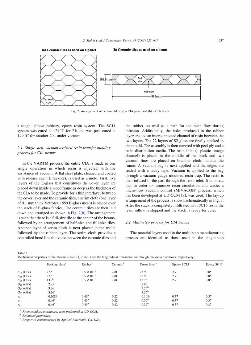
after the manufacturing operations. Fig. 2(a) shows a
geometric configuration of ceramic tiles. To facilitate for
an evaluation of the mechanical performance, the size of the
test pieces is reduced to the size of a beam, 889 mm long by
101.6 mm wide, as shown in Fig. 2(b).
The cover layer consisted of five layers of Vetrotex twill
weave 7781 E-glass fabric, also impregnated with an epoxy
resin. The total areal-density achieved is about 86.6 kg/m2.
The mechanical properties of the materials used are
presented in Table 1.
In the single-step and the multi-step manufacturing
processes, the stack is consolidated with a toughened epoxy
resin system, namely the Applied Poleramic SC15 epoxy
resin system. The SC15 system gels overnight at room
temperature and under vacuum. Additionally, a four-hour
post-cure at 149 8C is done. In the multi-step manufacturing
process [22], a more compliant Applied Poleramic SC11
epoxy resin system was also examined. The SC11 system is
Fig. 1. Example of CIA (dimensions in mm are not to scale).
S. Mahdi et al. / Composites: Part A 34 (2003) 635–647636
a tough, almost rubbery, epoxy resin system. The SC11
system was cured at 121 8C for 2 h and was post-cured at
149 8C for another 2 h, under vacuum.
2.1. Single-step, vacuum assisted resin transfer molding,
process for CIA beams
In the VARTM process, the entire CIA is made in one
single operation in which resin is injected with the
assistance of vacuum. A flat steel plate, cleaned and coated
with release agent (Freekote), is used as a mold. First, five
layers of the E-glass that constitutes the cover layer are
placed down inside a wood frame as deep as the thickness of
the CIA to be made. To provide for a thin interlayer between
the cover layer and the ceramic tiles, a scrim cloth (one layer
of 0.1 mm thick Vetrotex 1659 E-glass mesh) is placed over
the stack of E-glass fabrics. The ceramic tiles are then laid
down and arranged as shown in Fig. 2(b). The arrangement
is such that there is a full-size tile at the center of the beams,
followed by an arrangement of half-size and full-size tiles.
Another layer of scrim cloth is next placed in the mold,
followed by the rubber layer. The scrim cloth provides a
controlled bond line thickness between the ceramic tiles and
the rubber, as well as a path for the resin flow during
infusion. Additionally, the holes produced in the rubber
layer created an interconnected channel of resin between the
two layers. The 22 layers of S2-glass are finally stacked in
the mould. The assembly is then covered with peel ply and a
resin distribution media. The resin inlet (a plastic omega
channel) is placed in the middle of the stack and two
vacuum lines are placed on breather cloth, outside the
frame. A vacuum bag is next applied and the edges are
sealed with a tacky tape. Vacuum is applied to the bag
through a vacuum gauge mounted resin trap. The resin is
then infused in the part through the resin inlet. It is noted,
that in order to minimize resin circulation and waste, a
micro-flow vacuum control (MIVACON) process, which
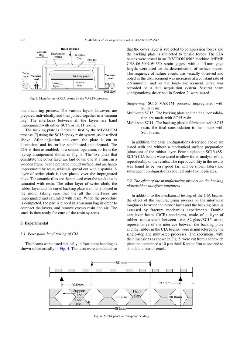
has been developed at UD-CCM [7], was used. The lay-up
arrangement of the process is shown schematically in Fig. 3.
After the stack is completely infiltrated with SC15 resin, the
resin inflow is stopped and the stack is ready for cure.
2.2. Multi-step process for CIA beams
The material layers used in the multi-step manufacturing
process are identical to those used in the single-step
Table 1
Mechanical properties of the materials used (1, 2 and 3 are the longitudinal, transverse and though-thickness directions, respectively).
Backing platea Rubbera Ceramicb Cover layera Epoxy SC15c Epoxy SC11c
E11 (GPa) 27.5 3.5 £ 1023 270 25.9 2.7 0.85
E22 (GPa) 27.5 3.5 £ 1023 270 25.9 2.7 0.85
E33 (GPa) 13.7b 3.5 £ 1023 270 13.7b 2.7 0.85
G12 (GPa) 2.85 2.85
G13 (GPa) 3.26 3.26b
G23 (GPa) 3.26b 3.26b
n12 0.1084 0.49b 0.22 0.1084 0.37 0.37
n23 0.46b 0.49b 0.22 0.39b 0.37 0.37
n13 0.46b 0.49b 0.22 0.39b 0.37 0.37
a From standard mechanical tests performed at UD-CCM.b Estimated properties.c Properties communicated by Applied Poleramic, CA, USA.
Fig. 2. Arrangement of ceramic tiles (a) a CIA panel and (b) a CIA beam.
S. Mahdi et al. / Composites: Part A 34 (2003) 635–647 637
manufacturing process. The various layers, however, are
prepared individually and then joined together in a vacuum
bag. The interfaces between all the layers are hand
impregnated with either SC15 or SC11 resins.
The backing plate is fabricated first by the MIVACOM
process [7] using the SC15 epoxy resin system, as described
above. After injection and cure, the plate is cut to
dimension, and its surface sandblasted and cleaned. The
CIA is then assembled, in a second operation, to form the
lay-up arrangement shown in Fig. 3. The five plies that
constitute the cover layer are laid down, one at a time, in a
wooden frame over a prepared mould surface, and are hand-
impregnated by resin, which is spread out with a spatula. A
layer of scrim cloth is then placed over the impregnated
plies. The ceramic tiles are then placed over the stack that is
saturated with resin. The other layer of scrim cloth, the
rubber layer and the cured backing plate are finally placed in
the mold, taking care that the all the interfaces are
impregnated and saturated with resin. When the procedure
is completed, the part is placed in a vacuum bag in order to
compact the layers, and remove excess resin and air. The
stack is then ready for cure of the resin systems.
3. Experimental
3.1. Four-point bend testing of CIA
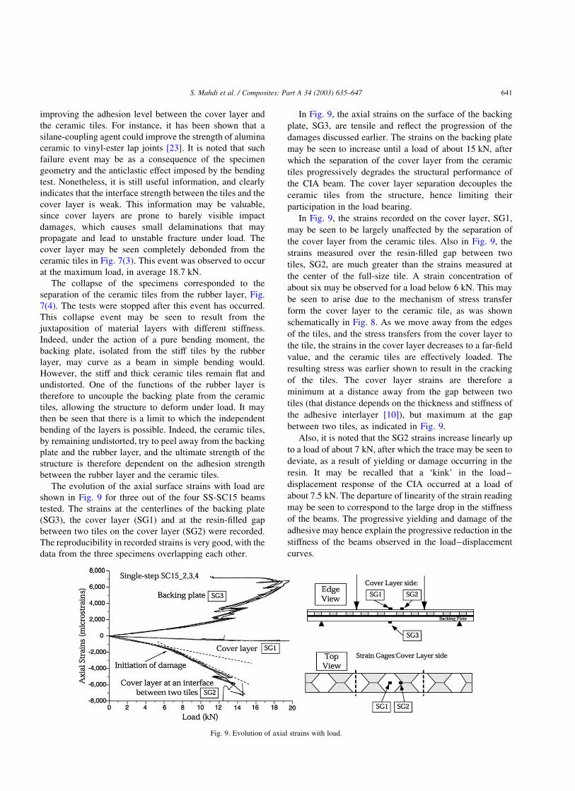
The beams were tested statically in four-point bending as
shown schematically in Fig. 4. The tests were conducted so
that the cover layer is subjected to compression forces and
the backing plate is subjected to tensile forces. The CIA
beams were tested in an INSTRON 8562 machine. MEME
CEA-06-500UW-350 strain gages, with a 15 mm gage
length, were used for the determination of surface strains.
The sequence of failure events was visually observed and
noted as the displacement was increased at a constant rate of
2.5 mm/min, and as the load–displacement curve was
recorded on a data acquisition system. Several beam
configurations, described in Section 2, were tested:
Single-step SC15 VARTM process; impregnated with
SC15 resin.
Multi-step SC15 The backing plate and the final consolida-
tion are made with SC15 resin.
Multi-step SC11 The backing plate is fabricated with SC15
resin; the final consolidation is then made with
SC11 resin.
In addition, the basic configurations described above are
tested with and without a mechanical surface preparation
(abrasion) of the rubber layer. Four single-step SC15 (SS-
SC15) CIA beams were tested to allow for an analysis of the
reproducibly of the results. The reproducibility in the results
was found to be very good (as will be shown later) and
subsequent configurations required only two replicates.
3.2. The effect of the manufacturing process on the backing
plate/rubber interface toughness
In addition to the mechanical testing of the CIA beams,
the effect of the manufacturing process on the interfacial
toughness between the rubber layer and the backing plate is
assessed by fracture mechanics experiments. Double
cantilever beam (DCB) specimens, made of a layer of
rubber sandwiched between two S2-glass/SC15 arms,
representative of the interface between the backing plate
and the rubber in the CIA beams, were manufactured by the
single-step and multi-step processes. The specimens, with
the dimensions as shown in Fig. 5, were cut from a sandwich
plate that contained a 10 mm thick Kapton film at one end to
simulate a starter crack.
Fig. 3. Manufacture of CIA beams by the VARTM process.
Fig. 4. A CIA panel in four-point bending.
S. Mahdi et al. / Composites: Part A 34 (2003) 635–647638

The single-step DCB coupons were fabricated in one
operation in much the same way as the single-step CIA
beams were fabricated (see Section 2.1). The 10 plies of S2-
glass fabric that constitutes the first arm of the DCB
specimens were laid down on the steel tool plate, followed
by the rubber layer. The Kapton film was then carefully
positioned at one end of the laminate. The second set of 10
ply of S2-glass fabric that constitutes the second arm of the
DCB specimens were then positioned over the stack. The
stack was finally bagged and impregnated by SC15 resin, as
shown in Fig. 3.
The multi-step DCB coupons were fabricated in two
operations similar to the multi-step CIA beams (see Section
2.2). First, a 10 ply S2-glass/epoxy plate was fabricated by
the VARTM process, and impregnated with SC15 resin. The
plate constituted the materials for the two arms of the DCB.
The plate was grit blasted, cleaned and cut to the dimensions
as shown in Fig. 5. The sandwich stack was then
manufactured in a second operation, by hand impregnation
of the SC15 or SC11 resins. A set of multi-step DCB
specimens was also manufactured in which the rubber layer
was not abraded.
Five specimens, 25 mm wide, were cut from each plate.
Aluminum end blocks (25 mm by 25 mm) were then bonded
at the delaminated end of the specimen (see Fig. 5). One
edge of the specimens was then painted white with a brittle
Enamel paint and marked at 5 mm intervals to enable crack
length to be monitored during the test. Crosshead speeds of
0.01 mm/min and 0.05 mm/min were used during the
loading and unloading cycles, respectively. The load and
the ram displacement were recorded on a computer
throughout the test, including the unloading cycle.
4. Four-point bend testing of CIA: results
4.1. Single-step (VARTM) CIA beams
The load–deflection curves of the four SS-SC15 CIA
beams, for which the rubber layer was mechanically
prepared, are shown in Fig. 6 wherein it is observed that
the reproducibility in strength is very good. The coefficients
of variation for the first visually observed failure load and
displacement were about 8%. In Fig. 6, the load –
displacement response of the CIA beams is seen to be
non-linear, with maximum displacements recorded of about
50–70 mm, which are several times the thickness of the
beams. Large deformation, material non-linearity and
damage progression are therefore important in the structural
response of the beams. The events leading to the progressive
deterioration of the structural performance of the specimens
were nevertheless observed to be similar for all the SS-SC15
beams, and they are described next.
For clarity, the load–displacement curve of the SS-
SC15_1 specimen is reproduced in Fig. 7. The load–
displacement curve of the CIA is linear for displacement
below about 2 mm. After 2 mm displacement a gradual
change in the stiffness of the beams is observed. At a
displacement of 7 mm, and a load of 7.5 kN, a ‘kink’ in the
load–displacement curve may be clearly observed. This
‘kink’ corresponds to a drastic change in the stiffness of the
beams. The non-linear response of the beams may be though
to be associated with the yielding and damage of the resin at
the resin-filled gaps between two tiles. Indeed, Huang et al.
[10] have shown that stress concentrations existed at that
location as a result of the discontinuities of the tiles. The
non-linear deformation of the resin will in-turn progress-
ively reduce the stiffness of the beam. This effect is later
confirmed by the analysis of the strain gauge readings.
After 7 mm displacement, the load increases steadily,
although with a lower stiffness, until a first fracture event is
seen to occur consistently at an average displacement and
load of 23.7 mm and 14.9 kN, respectively. This drop in
stiffness was accompanied by a noticeably audible cracking
Fig. 5. Mode I fracture DCB specimens.
Fig. 6. Load–deflection responses of SS-SC15 (VARTM) CIA beams.
S. Mahdi et al. / Composites: Part A 34 (2003) 635–647 639

noise and was due to the sudden release of strain energy that
appeared to have resulted from the separation of the cover
layer from the ceramic tiles, as shown in Fig. 7(2). The
separation of the cover layer was observed to initiate at the
edge of the beams, and in a symmetric fashion. The locus of
failure was interfacial.
The observation of the edges of the beams at that instant
during the tests also revealed the formation of discrete
tensile cracks in some ceramic tiles. The exact sequence of
event was, however, not observable. The cracking also
resulted from the process of stress transfer between the
cover layer and the ceramic tiles, as shown schematically in
Fig. 8. Stress transfers from the cover layer to the ceramic
tile, through the resin interlayer, in a shear lag process
originating at the resin-filled gaps between the tiles [10].
This shear lag process progressively increases the contri-
bution of the ceramic tiles to the structural stiffening,
resulting in high axial stresses being developed that could
generate cracks in the ceramic.
The next sequence of failure event was observed to be the
progressive separation of the cover layer from the ceramic
tiles, as the displacement is increased above 24 mm, as
shown in Fig. 7(2) and (3). The delamination progressed
from the edge toward the center of the beams, and from the
center half-tiles toward the center full-tile. The initiation
and the propagation of the separation of the cover layer form
the ceramic tiles was a repeatable event and it may be
possible to improve the strength of the CIA beams by
Fig. 7. Sequence of failure events of SS-SC15 CIA beams.
Fig. 8. Mechanism of stress transfer between the cover layer and the ceramic tiles.
S. Mahdi et al. / Composites: Part A 34 (2003) 635–647640
improving the adhesion level between the cover layer and
the ceramic tiles. For instance, it has been shown that a
silane-coupling agent could improve the strength of alumina
ceramic to vinyl-ester lap joints [23]. It is noted that such
failure event may be as a consequence of the specimen
geometry and the anticlastic effect imposed by the bending
test. Nonetheless, it is still useful information, and clearly
indicates that the interface strength between the tiles and the
cover layer is weak. This information may be valuable,
since cover layers are prone to barely visible impact
damages, which causes small delaminations that may
propagate and lead to unstable fracture under load. The
cover layer may be seen completely debonded from the
ceramic tiles in Fig. 7(3). This event was observed to occur
at the maximum load, in average 18.7 kN.
The collapse of the specimens corresponded to the
separation of the ceramic tiles from the rubber layer, Fig.
7(4). The tests were stopped after this event has occurred.
This collapse event may be seen to result from the
juxtaposition of material layers with different stiffness.
Indeed, under the action of a pure bending moment, the
backing plate, isolated from the stiff tiles by the rubber
layer, may curve as a beam in simple bending would.
However, the stiff and thick ceramic tiles remain flat and
undistorted. One of the functions of the rubber layer is
therefore to uncouple the backing plate from the ceramic
tiles, allowing the structure to deform under load. It may
then be seen that there is a limit to which the independent
bending of the layers is possible. Indeed, the ceramic tiles,
by remaining undistorted, try to peel away from the backing
plate and the rubber layer, and the ultimate strength of the
structure is therefore dependent on the adhesion strength
between the rubber layer and the ceramic tiles.
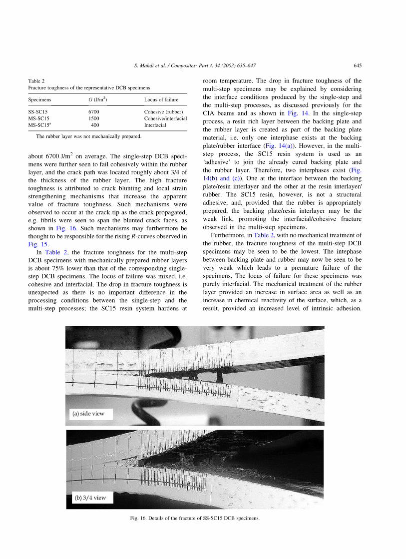
The evolution of the axial surface strains with load are
shown in Fig. 9 for three out of the four SS-SC15 beams
tested. The strains at the centerlines of the backing plate
(SG3), the cover layer (SG1) and at the resin-filled gap
between two tiles on the cover layer (SG2) were recorded.
The reproducibility in recorded strains is very good, with the
data from the three specimens overlapping each other.
In Fig. 9, the axial strains on the surface of the backing
plate, SG3, are tensile and reflect the progression of the
damages discussed earlier. The strains on the backing plate
may be seen to increase until a load of about 15 kN, after
which the separation of the cover layer from the ceramic
tiles progressively degrades the structural performance of
the CIA beam. The cover layer separation decouples the
ceramic tiles from the structure, hence limiting their
participation in the load bearing.
In Fig. 9, the strains recorded on the cover layer, SG1,
may be seen to be largely unaffected by the separation of
the cover layer from the ceramic tiles. Also in Fig. 9, the
strains measured over the resin-filled gap between two
tiles, SG2, are much greater than the strains measured at
the center of the full-size tile. A strain concentration of
about six may be observed for a load below 6 kN. This may
be seen to arise due to the mechanism of stress transfer
form the cover layer to the ceramic tile, as was shown
schematically in Fig. 8. As we move away from the edges
of the tiles, and the stress transfers from the cover layer to
the tile, the strains in the cover layer decreases to a far-field
value, and the ceramic tiles are effectively loaded. The
resulting stress was earlier shown to result in the cracking
of the tiles. The cover layer strains are therefore a
minimum at a distance away from the gap between two
tiles (that distance depends on the thickness and stiffness of
the adhesive interlayer [10]), but maximum at the gap
between two tiles, as indicated in Fig. 9.
Also, it is noted that the SG2 strains increase linearly up
to a load of about 7 kN, after which the trace may be seen to
deviate, as a result of yielding or damage occurring in the
resin. It may be recalled that a ‘kink’ in the load–
displacement response of the CIA occurred at a load of
about 7.5 kN. The departure of linearity of the strain reading
may be seen to correspond to the large drop in the stiffness
of the beams. The progressive yielding and damage of the
adhesive may hence explain the progressive reduction in the
stiffness of the beams observed in the load–displacement
curves.
Fig. 9. Evolution of axial strains with load.
S. Mahdi et al. / Composites: Part A 34 (2003) 635–647 641

4.2. Multi-step CIA beams
Load–deflection curves of the multi-step and single-step
beams are shown in Fig. 10. In Fig. 10(a), the load–
deflection responses of the two multi-step SC15 (MS-
SC15) beams tested may be compared with that of a
representative SS-SC15 beam. The structural responses of
the two MS-SC15 beams tested are quite different from
each other. The MS-SC15_2 beam failed at a low load by
the separation of the ceramic tiles from both the cover layer
and the rubber layer. This premature failure is thought to be
as a result of an improper surface preparation of the rubber
layer (such as contaminant left on the surface), for which
the exact causes were not identified in the present work. In
comparison, the MS-SC15_1 beam was found to be much
stronger, but not as strong as the single-step specimens. The
initiation of failure of the MS-SC15_1 beam was observed
to be by the separation of the cover layer from the ceramic
tiles, as for the single-step beams, but at a lower load of
11.7 kN (i.e. compared with 14.9 kN for the single-step
manufactured beams). The ultimate collapse of the beams
occured prematurely by the separation of the ceramic tiles
from the rubber layer. This represents a 20% drop in
strength. Consequently, the structural performance of the
MS-SC15 specimens may be seen to be poorer than that of
the SS-SC15 specimens. Furthermore, the initial stiffness of
the beam (i.e. for displacement lower than 20 mm) was
seen to be lower than that of the single-step manufactured
beam; about 50% lower. This will be shown to be a result of
the larger spacing between the tiles that results from the
multi-step fabrication process.
The load–deflection response of the two multi-step SC11
(MS-SC11) CIA beams tested is compared with that of a SS-
SC15 beam in Fig. 10(b). The scatter is relatively small. The
structural performance of the MS-SC11 beams compares
well with that of a SS-SC15 beam, although their initial
stiffness is lower. Also, the progressive degradation of the
MS-SC11 beams was observed to be comparable with that
of the SS-SC15 beams.
4.3. Effect of the surface mechanical preparation of the
rubber layer
In Fig. 11, the structural responses of single- and multi-
step manufactured beams, for which the rubber layer was
and was not mechanically abraded, are compared. It is
observed that the mechanical abrasion of the rubber layer
has a critical effect on the structural performance of the CIA
beams. In Fig. 11(a), the lack of abrasion leads to a
reduction in failure displacement and load of about 75 and
Fig. 10. Load–deflection responses of MS-SC15 and MS-SC11 CIA beams.
Fig. 11. Load–deflection responses of single- and multi-step (a) SC15 and (b) SC11 CIA beams. Effect of the mechanical roughening of the rubber.
S. Mahdi et al. / Composites: Part A 34 (2003) 635–647642

85% for the single-step and the MS-SC15 specimens. In Fig.
11(b), the mechanical performance of MS-SC11 beams for
which the rubber layer was and was not mechanically
prepared are compared. Again, it may be seen that the
mechanical performance is poorer for the specimen for
which the rubber layer was not mechanically prepared.
These beams failed by the separation of the rubber from the
backing plate, as a result of a poorer level of adhesion
between the two constituents, as shown schematically in
Fig. 12. Consequently, it may be seen that the surface
mechanical preparation of the rubber layer is necessary to
achieve optimum mechanical performance of the beams.
5. Four-point bend testing of CIA: discussion
In Fig. 10, it was observed that the manufacturing
process and the resin system have a large effect on the
structural performance of the beams. The structural
performance of SS-SC15 beams was seen to be superior to
any of the CIA beams tested in the present work. The
structural performance of the MS-SC15 beams was
comparatively seen to be the poorest of all the CIA
beams, as a result of a premature decohesion of the ceramic
tiles from the rubber layer. In contrast, the structural
performance of the MS-SC11 beam was seen to be
comparable, although with a lower initial stiffness, to that
of the single-step manufactured beams.
In Fig. 13, the observation of the cross-sectional areas
(spanning the width) of a single-step and a multi-step CIA
beam reveals that the gap spacing two tiles is in average 0.5
and 1.5 mm for the single-step and the multi-step CIA
beams, respectively. The difference in the confinement of the
tiles can be traced back to the manufacturing processes. In
the single-step process, the resin is infused, in one operation,
through the sections of the beam. As a result, the tiles may be
uniformly spaced and compacted. On the other hand, in the
multi-step process the backing plate, already manufactured
and cut to dimension, is solid and prevents the tiles to be as
well compacted. As a result, the gap in between two tiles is
seen to vary from tile to tile, and is generally greater than for
the single-step CIA beams. A larger gap spacing results in a
more compliant response of the multi-step beams. At the gap
between two tiles, it was shown that the stress transfers in a
shear-lag process, giving rise to the high strain concen-
trations observed in Fig. 9. For small gap spacing, the stress
transfer efficiency is high [24], therefore maximizing the
participation of the stiff ceramic tiles to the structural
stiffness of the CIA. Increasing the gap spacing decrease the
efficiency of the shear-lag process, resulting in a loss in
initial structural stiffness, since the contribution of the stiff
ceramic tile to the structural stiffness is diminished; multi-
step beams are more compliant than single-step beams.
Furthermore, it is startling that the single-step and the
MS-SC15 beams behave in different ways. Consider that in
the single-step process, the backing plate and the rubber
layer are bonded together at the same time as the CIA is
impregnated; the material layers are bonded at the same
time as the backing plate is made. A SC15 resin rich
interlayer is formed at the interface between the backing
plate and the rubber layer. It is reminded that a 0.1 mm thick
scrim cloth was inserted during manufacturing at that
location to ensure a constant interlayer thickness. As a
result, the transition between the backing plate and the
rubber layers may be thought to be smooth, with only one
interphase region forming close to the rubber layer, as
shown in Fig. 14(a). However, in the multi-step process,
Fig. 14(b) and (c), a cured backing plate is bonded to the
rubber layer. The interlayer resin rich zone, similar to an
adhesive interlayer in a bonded joint, may be seen to give
rise to two interphase regions, one above and one below the
interlayer resin rich zone. The interphase regions in the
multi-step manufactured beam may therefore be seen to be
weaker than for a single-step manufactured beams.
6. Effect of the manufacturing process on the level of
adhesion at the interface between the rubber layer and
the backing plate
The effect of the fabrication method on the level of
adhesion achieved between the backing plate and the rubber
Fig. 12. Relative motion between the backing plate and the upper layer of
the CIA.
Fig. 13. Single- and multi-step manufactured specimens.
S. Mahdi et al. / Composites: Part A 34 (2003) 635–647 643

layer is examined using DCB specimens, as was shown in
Fig. 5. Five DCB specimens were prepared for each
manufacturing process (SS-SC15, MS-SC15 and MS-
SC11).
Several data reduction methods were assessed; namely
the corrected beam theory (CBT) [25], the experimental
compliance [26], and the area [25] methods. In the CBT
approach, the strain energy release rate, G; may be
calculated from knowledge of the load and the opening
displacement of the arms and the measured crack length
(measured from the center of the loading blocks to the crack
tip with a traveling microscope), with a data reduction
technique presented in Ref. [25]. The experimental
compliance method (ECM) uses experimental data to
compute the value of fracture toughness, and the data
reduction technique used is described in Ref. [26]. The
specimens were not pre-cracked, and the initiation and
propagation values were determined in one loading/
unloading cycle. The area method involves the measure-
ment of the loading/unloading curves for successive
increments of crack length [25]. The strain energy release
rates were calculated from two consecutive loading lines,
corrected for zero displacement at zero loads.
Three specimens were used for the determination of G
by the compliance method and two specimens were used
for the determination of G by the area method. Fig. 15
shows the calculated Mode I fracture toughness for
single-step manufactured specimens. It may be noted that
the values calculated from the CBT and the ECM
approaches agree very well, and agree with the values
calculated from the area method.
Fracture toughness data, calculated with the CBT
approach, for the single-step and multi-step DCB specimens
are listed in Table 2. The value given in Table 2 is an
average of the propagation values (i.e. not taking into
consideration the initiation values). The loci of failure are
also given. It may be noted that the rising R-curves (i.e. the
resistance to crack propagation, G; increases with crack
length, a), as shown in Fig. 15, do not permit the calculation
of a single value for the fracture toughness of the specimens.
The values given in Table 2 are therefore only an indication
that may be use for a comparison of the results. Also, it was
not possible to assess the fracture toughness of the DCB
specimens bonded with the SC11 resin system. The load–
displacement curves of the MS-SC11 DCB specimens were
found to be highly non-linear. Furthermore, the onset of
crack growth was not well defined, and it was not possible to
note accurately the crack length, as required by the data
reduction method. Consequently, it was not possible to
calculate a value of fracture toughness. Consequently, only
the DCB specimens bonded with SC15 resin system are
analyzed in the present paper.
In Table 2, the manufacturing process may be seen to
have a significant effect on the values of Mode I fracture
toughness. For the specimens with the rubber layer
mechanically prepared, it may be seen that the single-step
DCB specimens were the toughest, with a toughness of
Fig. 14. SS-SC15 and MS-SC15 and SC11 CIA beams.
Fig. 15. Comparison between the fracture toughness values calculated by
the CBT [25], ECM [26] and area [25] approaches for the single-step
manufactured DCB.
S. Mahdi et al. / Composites: Part A 34 (2003) 635–647644
about 6700 J/m2 on average. The single-step DCB speci-
mens were further seen to fail cohesively within the rubber
layer, and the crack path was located roughly about 3/4 of
the thickness of the rubber layer. The high fracture
toughness is attributed to crack blunting and local strain
strengthening mechanisms that increase the apparent
value of fracture toughness. Such mechanisms were
observed to occur at the crack tip as the crack propagated,
e.g. fibrils were seen to span the blunted crack faces, as
shown in Fig. 16. Such mechanisms may furthermore be
thought to be responsible for the rising R-curves observed in
Fig. 15.
In Table 2, the fracture toughness for the multi-step
DCB specimens with mechanically prepared rubber layers
is about 75% lower than that of the corresponding single-
step DCB specimens. The locus of failure was mixed, i.e.
cohesive and interfacial. The drop in fracture toughness is
unexpected as there is no important difference in the
processing conditions between the single-step and the
multi-step processes; the SC15 resin system hardens at
room temperature. The drop in fracture toughness of the
multi-step specimens may be explained by considering
the interface conditions produced by the single-step and
the multi-step processes, as discussed previously for the
CIA beams and as shown in Fig. 14. In the single-step
process, a resin rich layer between the backing plate and
the rubber layer is created as part of the backing plate
material, i.e. only one interphase exists at the backing
plate/rubber interface (Fig. 14(a)). However, in the multi-
step process, the SC15 resin system is used as an
‘adhesive’ to join the already cured backing plate and
the rubber layer. Therefore, two interphases exist (Fig.
14(b) and (c)). One at the interface between the backing
plate/resin interlayer and the other at the resin interlayer/
rubber. The SC15 resin, however, is not a structural
adhesive, and, provided that the rubber is appropriately
prepared, the backing plate/resin interlayer may be the
weak link, promoting the interfacial/cohesive fracture
observed in the multi-step specimens.
Furthermore, in Table 2, with no mechanical treatment of
the rubber, the fracture toughness of the multi-step DCB
specimens may be seen to be the lowest. The intephase
between backing plate and rubber may now be seen to be
very weak which leads to a premature failure of the
specimens. The locus of failure for these specimens was
purely interfacial. The mechanical treatment of the rubber
layer provided an increase in surface area as well as an
increase in chemical reactivity of the surface, which, as a
result, provided an increased level of intrinsic adhesion.
Fig. 16. Details of the fracture of SS-SC15 DCB specimens.
Table 2
Fracture toughness of the representative DCB specimens
Specimens G (J/m2) Locus of failure
SS-SC15 6700 Cohesive (rubber)
MS-SC15 1500 Cohesive/interfacial
MS-SC15a 400 Interfacial
The rubber layer was not mechanically prepared.
S. Mahdi et al. / Composites: Part A 34 (2003) 635–647 645

Overall, the behavior of the single-step and multi-step DCB
coupons may be seen to be comparable with that of the CIA
beams.
7. Conclusions
Beams, representative of CIA, were tested in four-point
bending and have been shown to be able to support loads far
exceeding the load associated with the initial failure event.
The structural performance of the beams has been shown to
degrade progressively with increasing displacement. The
structures were shown to provide significant load capacity
and toughness before final collapse occurred. The structural
performance of a CIA beam has also been related to its
manufacturing process. CIA beams fabricated from a single-
step VARTM process outperformed beams manufactured
by a more conventional multi-step process. This is
encouraging since single-step manufacturing methods are
more efficient.
The structural performance of the beams was further-
more seen to be dependent on the performance of the
interfaces that compose the beams. Firstly, the surface
preparation of the rubber layer was seen to be essential for
the structural performance of the CIA beams. Secondly, the
adhesion between the rubber and the backing plate on one
hand, and the ceramic tiles on the other, was also seen to be
critical. Consequently, an increase in the mechanical
performance of the CIA beams may be achieved by the
tailoring of the strength of its interfaces. Hence, there is a
need to develop test coupons, representative of the different
interfaces present in the CIA beams, which can be used to
evaluate the performance of the interfaces.
DCB specimens, representative for the backing plate/
rubber interface of single-step and multi-step CIA beams
were tested. Coupons representative for the single-step
VARTM CIA beams failed by crack propagation in the
rubber layer (cohesive fracture of the rubber). On the other
hand, the coupons representative of the multi-step CIA
beams failed at the interface, although some rubber cohesive
failure zones were observed. The mechanical roughening of
the rubber layer also resulted in an improvement in the
adhesion between the GFRP and the rubber. The behavior of
the single-step and multi-step DCB coupons was compar-
able to that of the CIA beams.
Acknowledgements
The authors would like to acknowledge funding from the
Army Research Laboratory as part of the Strategic
Environmental Research and Development Program
(SERDP) (Grant DAAL01-98-K-0058) and the Composite
Materials Technology Center of Excellence program
established at the University of Delaware Center for
Composite Materials.
References
[1] Gama BA, Bogetti TA, Fink BK, Yu CJ, Claar TD, Eifert HH,
Gillespie Jr. JW. Aluminum foam integral armor: a new dimension in
armor design. Compos Struct 2001;52:381–95.
[2] Gama BA, Gillespie JW, Bogetti TA, Fink BK. Innovative design
and ballistic performance of lightweight composite integral armor.
Technology for the army’s transformation. SAE World Congress
and Exposition, Detroit; March 5–8, 2001. Paper No. 2001-01-
0888.
[3] Mahfuz H, Zhu Y, Haque A, Abutalib A, Vaidya U, Jeelani S, Gama
B, Gillespie JW, Fink BK. Investigation of high-velocity impact on
integral armor using finite element method. Int J Impact Engng 2000;
24(2):203–17.
[4] Gama BA, Gillespie JW, Mahfuz H, Bogetti TA, Fink BK. Effect of
non-linear material behavior on the through-thickness stress wave
propagation in multi-layer hybrid lightweight armor. In: Atluri SN,
Burst FW, editors. International Conference on Computational
Engineering and Sciences, 21–25 August 2000, vol. I. Los Angeles,
CA: Tech Science Press; 2000. p. 157–62.
[5] Heider D, Graf A, Fink BK, Gillespie JW. Feedback control of the
vacuum assisted resin transfer molding (VARTM) process. Proceed-
ings of the SPIE International Symposium on NDE Techniques for
Aging Infrastructure and Manufacturing: Process Control and Sensors
for Manufacturing; 1999.
[6] Kerang H, Shunliang J, Chuck Z, Wang B. Flow modeling and
simulation of SCRIMP for composites manufacturing. Composites,
Part A 2000;31(1):79–86.
[7] Gama BA, Li H, Li W, Paesano A, Heider D, Gillespie JW.
Improvement of dimensional tolerances during VARTM processing.
Proceedings of 33rd International SAMPE Technical Conference,
Nov 5–8 2001; 2001. p. 1415–27.
[8] Fink BK, McKnight SH, Gillespie JW. Co-injection resin transfer
molding for optimization of integral armor. Proceedings of the 21st
Army Science Conference: Science and Technology for Army After
Next, Norfolk, VA; June 15–17, 1998.
[9] Pike T, McArthur M, Schade D. Vacuum assisted resin transfer
molding of a layered structural laminate for application on ground
combat vehicles. Int SAMPE Tech Conf 1996;28(Nov):374–80.
[10] Huang XG, Gillespie JW, Kumar V, Gavin L. Mechanics of integral
armor: discontinuous ceramic-cored sandwich structure under tension
and shear. Compos Struct 1996;36:81–90.
[11] Monib AM, Gillespie JW. Damage tolerance of composite laminates
subjected to ballistic impact. Proceedings of ANTEC 98, Brookfield,
CT: Society of Plastics Engineers; 1998. p. 1463–7.
[12] DeLuca E, Prifti J, Betheney W, Chou SC. Ballistic impact damage of
S2-glass reinforced plastic structural armor. Compos Sci Technol
1998;58(9):1453–61.
[13] Sherman D. Impact failure mechanisms in alumina tiles on finite
thickness support and the effect of confinement. Int J Impact Engng
2000;24(3):313–28.
[14] Camacho GT, Ortiz M. Computational modeling of impact
damage in brittle materials. Int J Solids Struct 1996;33(20–22):
2899–938.
[15] Martinez MA, Chocron IS, Rodriguez J, Sanchez Galvez V, Sastre
LA. Confined compression of elastic adhesives at high rates of strain.
Int J Adhes Adhes 1998;18(6):375–83.
[16] Zaera R, Sanchez-Saez S, Perez-Castellanos JL, Navarro C. Modeling
of the adhesive layer in mixed ceramic/metal armors subjected to
impact. Composites, Part A 2000;31:823–33.
[17] Chocron Benloulo IS, Sanchez-Galvez V. A new analytical model to
simulate impact onto ceramic/composite armors. Int J Impact Engng
1998;21(6):461–71.
[18] Fellows NA, Barton PC. Development of impact model for
ceramic-faced semi-infinite armour. Int J Impact Engng 1999;
22(8):793–811.
S. Mahdi et al. / Composites: Part A 34 (2003) 635–647646

[19] Davila CG, Chen T-K. Advanced modeling strategies for the analysis
of tile-reinforced composite armor. Appl Compos Mater 2000;7(1):
51–68.
[20] Davila CG, Smith C, Lumban-Tobing F. Analysis of thick sandwich
shells with embedded ceramic tiles. NASA TM-110278 1996;12.
[21] Chen T-K, Davila CG, Baker DJ. Analysis of tile-reinforced
composite armor. Part 2. Viscoelastic response modeling. Proceed-
ings of the 21st Army Science Conference, Science and Technology
for Army After Next, Norfolk, VA; June 1998.
[22] Davila CG, Chen T-K, Baker DJ. Analysis of tile-reinforced
composite armor. Part 1. Advanced modeling and strength analyses.
Proceedings of the 21st Army Science Conference, Science and
Technology for Army After Next, Norfolk, VA; June 1998.
[23] Tanoglu M, McKnight SH, Palmese GR, Gillespie JW. Use of silane
coupling agents to enhance the performance of adhesively bonded
alumina to resin hybrid composites. Int J Adhes Adhes 1998;18:431–4.
[24] Mahdi S, Gillespie JW. Finite element analysis of multi-functional
tile-reinforced sandwich constructions. Sent for review in Composites
Part B:Engineering, 2003.
[25] Hashemi S, Kinloch AJ, Williams JG. The analysis of interlaminar
fracture in uniaxial fibre-polymer composites. Proc R Soc Lond 1990;
A427:173–99.
[26] ASTM D 5528-94a, Standard test method for Mode I interlaminar
fracture toughness of unidirectional fiber-reinforced polymer matrix
composites. Annual book of ASTM standards, vol. 15.03. USA:
ASTM; 1997.
S. Mahdi et al. / Composites: Part A 34 (2003) 635–647 647