effect of variation in the strength of concrete and ... · = ultimate strain in concrete (usually...
TRANSCRIPT
EFFECT OF VARIATION IN THE STRENGTH OF CONCRETE AND
REINFORCING BARS ON THE BEHAVIOR OF RC BEAMS
A. Amin1 & N. H. M. K. Serker2*
1Department of Civil Engineering, European University of Bangladesh, Dhaka, Bangladesh
2Department of Civil Engineering, Rajshahi University of Engineering & Technology, Rajshahi,
Bangladesh *Corresponding Author: [email protected]
ABSTRACT
Reinforced concrete members are designed with specified code specifications. In general, the
compressive strength of concrete and the yield strength of steel are assumed in the design process.
Compressive strength of concrete depends on a number of factors and generally shows some degree of
variation from the desired strength. On the other hand, reinforcing bars with higher yield strength than
that recommended in the Bangladesh National Building Code is available in the market and
being used in construction. Therefore, increase in yield strength of steel and decrease in compressive
strength of concrete may have adverse effects on the flexural behavior of beams. This study includes
the behavior of reinforced concrete beam due to this variation in strengths. This study shows that
some certain beam turns into over-reinforced from under-reinforced state as well as
compression controlled from tension-controlled state due to change in strengths. Besides, reduction in
ductility is also observed due to strength variation in the properties of the major constituent
materials. A complete theoretical analysis along with some experimental investigation is presented in
this paper.
Keywords: Ductility; high-strength steel; BNBC; beam behavior
INTRODUCTION
The building construction industry is one of the emerging sectors of Bangladesh and
reinforced concrete (RC) building frames are the most popular choice in this regard. Recent
earthquakes as well as some tragic incidents have raised the issue of performance of these buildings
during an earthquake or under ultimate load. Concrete and reinforcing bars are the chief
constituent materials in RC buildings. Since reinforcing bars are made in the factory its quality can
be easily controlled and high strength steel bars are also available in the local market. The use of high-
strength steel bars offers several advantages, such as the reduction of the reinforcement ratio,
less cost for reinforcement placement, reduced reinforcement congestion, better concrete placement
etc. On the other hand the quality of concrete is difficult to control and this job has become an
impossible one in Bangladesh because of the crude construction technology and no-trained workers.
Another important issue is the use of higher strength steel than that specified in the Bangladesh
National Building Code (BNBC). BNBC (1993) adopted some of the ASTM Standards for structural
steel and allowable yield strength of steel reinforcing bars was limited to 410 MPa (60 ksi). The
important concern is that RC members are designed with Code specified maximum yield strength of
410 MPa and constructed with locally available higher grade steels such as thermo mechanically
treated (TMT) high strength structural steel bars having yield strength up to 500 MPa or 72.5 ksi
(Islam, 2010). Therefore such increase in yield strength of steel and decrease in compressive strength
of concrete may have adverse effects on the behavior of RC flexural members and the beam would
not achieve adequate ductility under ultimate load. This study aims to focus on
1. the behavior of beams using TMT high strength structural steel bars and concrete having
specified design strength.
2. the behavior of beams using TMT high strength structural steel bars and concrete having
strength less than the specified design strength.
Proceedings of 3rd International Conference on Advances in Civil Engineering, 21-23 December 2016, CUET, Chittagong, Bangladesh Islam, Imam, Ali, Hoque, Rahman and Haque (eds.)
486

2
METHODOLOGY
The study is divided into two steps (i) analytical study with some typical beam sections (ii)
experimental investigations. In each case ultimate load carrying capacity of the beam and ductility
was measured.
Ductility is an important issue in the design of structure and structural member and is defined as the
ability of the material/member to sustain deformation beyond the elastic limit while maintaining a
reasonable load carrying capacity until total failure (Pam et. al., 2001). Ductility is a valuable
structural property as it allows stress redistribution and provides warning of impending failure. The
ductility of a reinforced concrete beam depends on the amount of tension reinforcement, the amount
of compression reinforcement and the strength and ductility of the materials used (Sarkar et. al.,
1997).
Generally, reinforced concrete beams are under-reinforced by design, so that failure is initiated by
yielding of the steel reinforcement, followed, after considerable deformation at no substantial loss of
load carrying capacity, by concrete crushing and ultimate failure. That is a ductile mode of failure is
desired and is ensured by designing the tensile reinforcement ratio to be substantially below the
balanced ratio, which is the ratio at which steel yielding and concrete crushing occur simultaneously.
The mathematical expression of balanced reinforcement ratio (Nilson et. al., 2004) is
𝜌𝑏 = 0.85 𝛽1𝑓′𝑐
𝑓𝑦
∈𝑢
∈𝑢+∈𝑦 (1)
where,
𝑓′𝑐= compressive strength of concrete,
𝑓𝑦= yield strength of steel,
∈𝑢= ultimate strain in concrete (usually taken as 0.003),
∈𝑦= yield strain of steel and
𝛽1 = constant depends on compressive strength of concrete. It is clear from Eq. (1) that for a
particular beam section the balanced reinforcement ratio depends on the material properties. Besides
upper limit of the reinforcement ratio has been introduced in the design Codes (e.g. ACI 318-05) to
guarantee ductility
𝜌𝑚𝑎𝑥 = 0.85 𝛽1𝑓′𝑐
𝑓𝑦
∈𝑢
∈𝑢+0.004 (2)
The reinforcement ratio thus provides a measurement for ductility and the ductility corresponding to
the maximum allowable reinforcement ratio provides a measure of the minimum acceptable ductility.
The mode of failure is another important issue which is defined as a function of net tensile strain. The
net tensile strain is the tensile strain in the extreme tension steel at nominal strength. According to
ACI Code (2005), a beam section is said to be tension-controlled if the net tensile strain is equal to or
larger than 0.005 and compression-controlled if the net tensile strain is equal to or less than 0.002. A
section is in a transition region between compression- and tension-controlled sections.
In this article the curvature ductility was considered. The ductility factor was taken as the ratio of the
curvature at yield and ultimate condition. The ductility can be estimated as shown below:
Fig. 1: Calculation of ductility
Proceedings of 3rd International Conference on Advances in Civil Engineering, 21-23 December 2016, CUET, Chittagong, Bangladesh Islam, Imam, Ali, Hoque, Rahman and Haque (eds.)
487
3
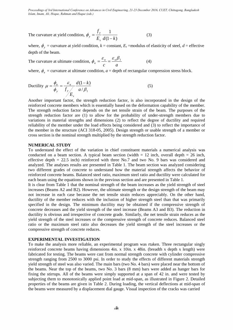
The curvature at yield condition, )1(
1
kdE
f
s
y
y
(3)
where, y = curvature at yield condition, k = constant, Es =modulus of elasticity of steel, d = effective
depth of the beam.
The curvature at ultimate condition, ac
uu
u
1
(4)
where, u = curvature at ultimate condition, a = depth of rectangular compression stress block.
Ductility
1/
)1(
a
kd
E
f
s
y
u
y
u (5)
Another important factor, the strength reduction factor, is also incorporated in the design of the
reinforced concrete members which is essentially based on the deformation capability of the member.
The strength reduction factor depends on the net tensile strain of the beam. The purposes of the
strength reduction factor are (1) to allow for the probability of under-strength members due to
variations in material strengths and dimensions (2) to reflect the degree of ductility and required
reliability of the member under the load effects being considered and (3) to reflect the importance of
the member in the structure (ACI 318-05, 2005). Design strength or usable strength of a member or
cross section is the nominal strength multiplied by the strength reduction factor.
NUMERICAL STUDY
To understand the effect of the variation in chief constituent materials a numerical analysis was
conducted on a beam section. A typical beam section (width = 12 inch, overall depth = 26 inch,
effective depth = 22.5 inch) reinforced with three No.7 and two No. 9 bars was considered and
analyzed. The analyses results are presented in Table 1. The beam section was analyzed considering
two different grades of concrete to understand how the material strength affects the behavior of
reinforced concrete beams. Balanced steel ratio, maximum steel ratio and ductility were calculated for
each beam using the equations shown in the previous section and are presented in Table 1.
It is clear from Table 1 that the nominal strength of the beam increases as the yield strength of steel
increases (Beams A2 and B2). However, the ultimate strength or the design strength of the beam may
not increase in each case because the net tensile strain reduces appreciably. On the other hand,
ductility of the member reduces with the inclusion of higher strength steel than that was primarily
specified in the design. The minimum ductility may be obtained if the compressive strength of
concrete decreases and the yield strength of the steel increase (Beams A3 and B3). The reduction in
ductility is obvious and irrespective of concrete grade. Similarly, the net tensile strain reduces as the
yield strength of the steel increases or the compressive strength of concrete reduces. Balanced steel
ratio or the maximum steel ratio also decreases the yield strength of the steel increases or the
compressive strength of concrete reduces.
EXPERIMENTAL INVESTIGATION
To make the analysis more reliable, an experimental program was rtaken. Three rectangular singly
reinforced concrete beams having dimensions 4in. x 10in. x 48in. (breadth x depth x length) were
fabricated for testing. The beams were cast from normal strength concrete with cylinder compressive
strength ranging from 2500 to 3000 psi. In order to study the effects of different materials strength
yield strength of steel was also varied. The main bars (two No. 4 bars) were placed near the bottom of
the beams. Near the top of the beams, two No. 3 bars (8 mm) bars were added as hanger bars for
fixing the stirrups. All of the beams were simply supported at a span of 42 in. and were tested by
subjecting them to monotonically applied point load at mid-span, as illustrated in Figure 2. Detailed
properties of the beams are given in Table 2. During loading, the vertical deflections at mid-span of
the beams were measured by a displacement dial gauge. Visual inspection of the cracks was carried
Proceedings of 3rd International Conference on Advances in Civil Engineering, 21-23 December 2016, CUET, Chittagong, Bangladesh Islam, Imam, Ali, Hoque, Rahman and Haque (eds.)
488

4
Table 1: Numerical analysis results
Sl.
No. 𝑓′𝑐
(ksi)
𝑓𝑦
(ksi
)
Steel
ratio
Balance
d
steel
ratio
Max.
steel
ratio
Net
tensile
strain
Strength
reductio
n
factor
Mode of
failure
Ductilit
y
Nominal
Moment
Capacit
y
(k-ft)
Ultimat
e
Momen
t
Capacit
y
(k-ft)
A1 3.0 60.0 0.014 0.0214 0.0155 0.0050 0.90 Tension 2.24 356.7 321.0
A2 3.0 72.5 0.014 0.0163 0.0128 0.0033 0.76 Transition 1.53 413.2 315.0
A3 2.5 72.5 0.014 0.0136 0.0107 0.0024 0.68 Transition 1.24 392.5 265.0
B1 4.0 60.0 0.014 0.0285 0.0206 0.0077 0.90 Tension 3.07 374.4 337.0
B2 4.0 72.5 0.014 0.0217 0.0171 0.0059 0.90 Tension 2.10 439.0 395.1
B3 3.5 72.5 0.014 0.0190 0.0150 0.0048 0.69 Transition 1.79 428.0 295.0
out throughout the tests. The test was terminated when the specimen failed completely, i.e. when the
resistance of the specimen dropped. The load-deflection plot and failure patterns are shown in Fig. 3
and 4 respectively.
Fig. 2: Beam cross section and loading arrangement
Table 2: Properties of the beam specimen
Sl.
No. 𝑓′𝑐
(ksi)
𝑓𝑦
(ksi)
Balance
d
steel
ratio
Max.
steel
ratio
Net
tensile
strain
Strength
reductio
n
factor
Mode of
failure
Ductilit
y
Deflectio
n (in)
Ultimat
e
Load
(k)
C1 2.93 60.0 0.021 0.015
1
0.005
3 0.90 Tension 2.51 0.26 10.5
C2 2.97 72.5 0.016 0.012
7
0.004
0 0.66
Transitio
n 1.74 0.18 12.1
C3 2.52 72.5 0.014 0.010
8
0.002
9 0.61
Transitio
n 1.44 0.14 12.5
4 in.
10 in. 5.87 in.
(a) Beam cross section
P
3.5 ft.
1.75 ft
(b) Loading arrangement
Proceedings of 3rd International Conference on Advances in Civil Engineering, 21-23 December 2016, CUET, Chittagong, Bangladesh Islam, Imam, Ali, Hoque, Rahman and Haque (eds.)
489

5
Fig. 3: Typical load- deflection curves
Fig. 4: Failure pattern of experimental beams
Experimental Results
The experimental program was designed in such a way that the variation of the material strengths on
the behavior of beam can be studied. From the numerical study results it is clear that a section may
turn into over-reinforced if the strength of concrete decreases or strength of steel increases. Therefore,
the tension reinforcement may or may not yield before the concrete in the compression zone is
crushed. If the strength of the materials remains the same as it was considered in the design the
reinforcement ratio may lie below the allowable maximum amount as a result the tension
reinforcement will yield before the concrete is crushed and the beam will fail in a ductile manner. If
the reinforcement ratio becomes larger than the allowable maximum, the concrete will be crushed
without prior yielding of the tension reinforcement and the beam will fail in a brittle manner.
Beam C1 was designed considering compressive strength of 3000 psi and yield strength of steel as
60,000 psi. Due to some limitations, measurement of strain of steel or concrete was not possible. It
was expected from the previous numerical study that the use of higher strength steel or lower strength
concrete will affect the behaviour of the beam significantly. From the experiment the ultimate load
0
2
4
6
8
10
12
14
0 0.05 0.1 0.15 0.2 0.25 0.3
Load
(K
ip)
Deflection(in)
Case 1
Case 2
Case 3
Beam C1
Beam C2
Beam C3
Proceedings of 3rd International Conference on Advances in Civil Engineering, 21-23 December 2016, CUET, Chittagong, Bangladesh Islam, Imam, Ali, Hoque, Rahman and Haque (eds.)
490

6
capacity of the beam was measured as 10.5, 12.1 and 12.5 kips for beam C1, C2 and C3 respectively.
It is evident that the load carrying capacity of the beam has been increased after increasing the yield
strength of steel. However, the ultimate load of beam C3 was larger than the expected. It is
noteworthy that the deflection of the beam specimens reduces as the yield strength of steel increases
or compressive strength of concrete decreases. The measured deflections are well correlated with the
theoretical ductility. It is evident from the analytical study that there is a remarkable effect on the
mode of failure of the beam and the beam which was initially designed as an under-reinforced section
may turn into an over-reinforced section i.e. the beam may also fail by crushing of concrete instead of
yielding of steel. The experimental beam also reflects the same as it can be seen from Figure 4.
CONCLUSIONS
In the design of a reinforced concrete beam, both the flexural strength and ductility need to be
considered. However, more importance is usually given to the flexural strength and only a simple
check is carried out to ensure that a certain minimum level of ductility is provided by keeping the
beam under-reinforced. From the structural safety point of view, ductility is as important as strength.
A good ductility would provide the beam with a much better chance of survival when it is overloaded,
attacked by a severe earthquake or subjected to an accidental impact.
From the above, it is evident that the major factors affecting the flexural strength and ductility of a
reinforced concrete beam section are the concrete grade, yield strength of steel and tension steel ratio.
In the case of a singly reinforced section, at a fixed concrete grade, the use of a higher tension steel
ratio leads to a higher flexural strength but a lower ductility. Hence, the increase in flexural strength is
achieved by compromising ductility.
When specified design strength and actual strength remain the same, then the steel ratio is below the
allowable maximum steel ratio thus beam shows tension failure and produce higher deflection and
ductility. When compressive strength remain the same but steel strength is increased, then beam
shows larger nominal strength and produces relatively lower deformation and ductility. In case
compressive strength is decreased but steel strength is increased which may be a common case in
Bangladesh, the steel ratio increases and mode of failure of the beam is also changed and results lower
deformation and ductility.
REFERENCES ACI Committee 318. 2005. Building Code Requirements for Structural Concrete (ACI 318-05)
and Commentary, American Concrete Institute, Farmington Hills, MI.
ASTM A615/A615M-09. 2009. Standard Specifications for Deformed and Plain Carbon-Steel
Bars for Concrete Reinforcement, ASTM International, West Conshohocken, PA.
Bangladesh National Building Code. 1993. Housing and Building Research Institute, Dhaka,
Bangladesh.
Islam, MA. 2010. Thermo Mechanically Treated Advanced Steels for Structural applications,
Proceedings of MARTEC 2010, the International Conference on Marine Technology, 11-12
December, 2010, Dhaka, Bangladesh.
Nilson, AH; Darwin, D and Dolan, CW. 2004. Design of Concrete Structures, Thirteenth edition.
McGraw Hill
Pam, HJ; Kwan, AKH and Islam, MS. 2001. Flexural strength and ductility of reinforced normal- and
high-strength concrete beams. Proceedings of the Institution of Civil Engineers, Structures and
Buildings, 146(4): 381–389.
Sarkar, S; Adwan, O. and Munday JGL. 1997. High strength concrete: an investigation of the flexural
behaviour of high strength RC beams. Structural Engineer, 75(7):115–121.
Proceedings of 3rd International Conference on Advances in Civil Engineering, 21-23 December 2016, CUET, Chittagong, Bangladesh Islam, Imam, Ali, Hoque, Rahman and Haque (eds.)
491