effect of welding residual stress on along-wind...
TRANSCRIPT

Research ArticleEffect of Welding Residual Stress on Along-Wind Fatigue Life ofWelded Joints in Guyed Mast
Weilian Qu Min Wang and Qiang Zhou
Hubei Key Laboratory of Roadway Bridge and Structure Engineering Wuhan University of Technology WuhanHubei 430070 China
Correspondence should be addressed to Weilian Qu quweilian_wh126com
Received 13 June 2019 Revised 2 December 2019 Accepted 9 December 2019 Published 27 January 2020
Academic Editor Dario Di Maio
Copyright copy 2020 Weilian Qu et al +is is an open access article distributed under the Creative Commons Attribution Licensewhich permits unrestricted use distribution and reproduction in any medium provided the original work is properly cited
On the premise of only considering along-wind effect on guyed mast the influence of welding residual stress on the fatigue life ofwelded joints is evaluated in this paper Since the sum of residual stress and along-wind-induced dynamic stress exceeds the yieldstrength of structural steel the effect of residual stress relaxation is included in the numerical analysis +e multiscale finiteelement analysis of guyedmast is developed in order to capture accurately stress field distribution of welded joint for the ldquowelding-wind-inducedrdquo case in which both residual stress and along-wind-induced stress are taken into consideration and the stressresponse characteristics at fatigue critical point of welded joints are pointed out It is found that the ldquowelding-wind-inducedrdquo stressfield of welded joint can be approximately considered as multiaxial proportional loading state and hence the stress-based vonMises criterion can be adopted to evaluate the fatigue life of welded joints Based on the S-N curve of stress fatigue life for weldedspecimens with structural steel commonly used in guyed masts the fatigue damage of key welded joints is predicted and as aconsequence the influence of welding residual stress on the fatigue life of welded joints is discussed
1 Introduction
Guyed mast is a kind of widely used wind-sensitive struc-ture Due to the characteristics of high flexibility andlightweight welded joints of the guyed mast are vulnerableto long-term strong wind load which may induce severefatigue damage at weld seams +erefore there is great needto predict fatigue life of welded joints of such flexible steelstructure
In the field of fatigue life prediction of flexible structuresunder strong wind load Wirsching and Shehata [1] pro-posed a design method for high-cycle fatigue according tothe improved probability-based PalmgrenndashMiner (P-M)rule and rain-flow counting method Peil and Telljohann [2]studied the fatigue life of flexible high-rise structures underwind loads Tovo [3] analyzed the relation between fatiguedamage assessment and counting method and proposed anew rain-flow damage assessment method which can givesatisfactory approximate fatigue damage prediction undercombined wide- and narrow-band Gaussian loads Repetto
and Solari [4] assessed the wind-induced fatigue damage ofseveral types of mast structures in both downwind andcrosswind directions when the changes of wind speed andwind direction were considered However in these re-searches the influence of residual stresses of welded jointson fatigue life is ignored Horas et al [5] proposed theapplication of modal superposition technique combinedwith elastoplastic analysis to evaluate the fatigue crackinitiation of structural members Based on the materialdamage-elastoplastic-coupled mechanical model He et al[6] used the continuous damage mechanics (CDM) modulein the ABAQUS program to study fatigue performance ofwind turbine gears caused by tolling contact Ziegler et al [7]analyzed fatigue crack growth at two structural hot spots byusing a fracture mechanics model applying Parisrsquo law andstudied load sequence and weather seasonality influencefatigue crack growth for monopile-based offshore windturbines Lecheb et al [8] investigated dynamic crack fatiguelife of a 25m length wind turbine blades and discussed theinfluence of displacement strain stress andmode shapes on
HindawiShock and VibrationVolume 2020 Article ID 6467354 12 pageshttpsdoiorg10115520206467354
crack growth Wang and Soutis [9] studied fatigue perfor-mance of composite T joints used in wind turbine blades withvarious fibre reinforcement architectures and analyzed stressdistribution and initiation and growth of a delaminating crackby developing a finite element model Fang et al [10] assessedwind-induced fatigue of large-scale complicated high-risesteel structure by using equivalent structural stress methodand hot spot stress method as well as nominal stress methodHosseiny and Jakobsen [11] used the submodel method tostudy the fatigue crack growth life of offshore wind turbineblades under wind force Do et al [12] estimated fatigue life ofwind turbine tower bases throughout Colorado and discussedthe effects of wind distribution and turbulence intensityShuang and Song [13] investigated crack initiation andgrowth life of wind turbine blades by using the linear cu-mulative damage theory and linear crack propagation theoryand found that non-Gaussian characteristics of wind inflowshad a noticeable influence on both extreme response andfatigue damage Since it is very difficult to estimate the re-sidual stress distribution along the crack path as pointed outby Colombi and Dolintildeski [14] in the previous research theeffect of welding residual stress on the fatigue life of weldedjoint welds was neglected
Weld seams are weakness in fatigue life of welded jointsof high-rise structures Due to the difficulty in determiningwelding residual stress field of weld joint the effect of re-sidual stress on fatigue life of weld joint is so complicatedthat it is still not fully understood today Hence the influenceof welding residual stress field is still questionable
+is paper presents a method to study the effect ofwelding residual stress on the fatigue life of welded joints ofthe guyed mast subjected to along-wind load A multiscalefinite element analysis method is proposed to calculate theldquowelding-wind-inducedrdquo stress of welded joints with theconsideration of residual stress relaxation when weldingresidual stress is superimposed on wind-induced stress As acomparison the ldquowind-inducedrdquo stress of welded joints isalso calculated neglecting welding residual stress It is foundthat the three-dimensional stress field of welded joint can beapproximately considered to be multiaxial proportional andso the stress-based vonMises criterion can be used to predictthe fatigue life of welded joints +en the welded specimenswith structural steel commonly used in the guyed mast aretested to obtain the S-N curve of stress fatigue life and thefatigue damage value of key welded joints is calculated basedon the Miner linear cumulative fatigue damage model
2 Multiscale Finite Element Analysis of Along-Wind ldquoWelding-Wind-Inducedrdquo Stress ofWelded Joints
21 Multiscale Finite Element Modeling of Along-Wind-In-duced Stress of Welded Joints +e along-wind-induced re-sponse of guyed mast can be given by
[M] euroX1113966 1113967 +[C] _X1113966 1113967 + f X t1113864 1113865 P t (1)
where [M] [C] and f X t1113864 1113865 are the mass matrix thedamping matrix and the restoring force vector respectively
X _X1113966 1113967 and euroX1113966 1113967 are the horizontal displacement velocityand acceleration vectors of concentrated masses respec-tively and P t is the wind load vector acting on the nodallayers where the lumped masses are concentrated
+e guyed mast structure is composed of beam and cableas well as welded gusset plate at the beam-cable connectionUnder the action of wind various structural components ofthe mast structure will produce different dynamic responsesIn order to accurately obtain the along-wind-induced stressfield of the welded joints element types with different scalesare used for different structural components Due to thecalculation ability limitation of the desktop computer it isimpossible to analyze precisely all the welded gusset plates andwelds between cables and main structures Only the mostdisadvantageous welded joints are modeled and analyzed indetail Accordingly the multiscale finite element model forguyed mast includes the following (1) elastic beam elementbased on the meter scale mainly used in truss element of themain structure (2) strut element based on the meter scalemainly used for cable members considering that the cable ofthe guyed mast will be pretensioned to ensure that the cable isalways in tension state when wind-induced vibration occursin guyedmast the tensionedmember element can be used (3)elastic solid element based on the centimeter scale mainlyused for welded gusset plates (4) elastic-plastic solid elementbased on the millimeter scale mainly used for welds
For the mast structure shown in Figure 1 the guyed mastis a steel lattice truss which consists of steel tubular chordshaving a diameter Φ1026 and steel tubular cross webshaving diameterΦ544 +e total height of the guyed mast is152m and the cross section of the mast is a uniformequilateral triangle with each side having a length of 10m+e lattice trussed mast is divided into 92 segments witheach segment having a length of 125m +ree gusset platesare welded to the chord at each vertex of the triangle at theheight 55m of the mast and the other three gusset plates arewelded to the chord each vertex of the triangle at the height115m of the mast as shown in Figure 1 Each gusset plate isconnected to a guying cable +e projection length of thecables is 70m and the projection angle between any ad-jacent two cables at each layer is equal to 120deg All membersof the mast are made of the Q35 steel with a modulus ofelasticity of 20times1011Nm2 while the guying cables aremade of a galvanized steel wire with a modulus of elasticityof 12times1011Nm2 +e cables connecting the upper level ofgusset plates have a diameter of 145mm with a cross-sectional area of 2688times10minus 4m2 while the cables connectingthe lower level of joint plates have a diameter of 185mmwith a cross-sectional area of 165times10minus 4m2 (Figure 1) +estructure of the welded joints between the cable and the mastis shown in Figure 2
For this guyed mast structure the commercial finiteelement program ANSYS is adopted to establish its multi-scale finite element model in which BEAM44 element withmeter scale LINK10 element with meter scale SOLIID45element with centimeter scale and SOLIID95 element withmillimeter scale are selected for beam cable gusset platesand weld seams respectively +e multiscale finite elementmodel of the guyed mast is shown in Figure 3
2 Shock and Vibration
22 Finite Element Simulation of Residual Stress in WeldedJoint +e residual stresses in welded joints can be simulatedand calculated by ANSYS +erefore it is necessary to
establish a common geometric model and element meshingmodel for both thermal analysis and thermoelastic-plasticanalysis +e temperature field time history during weldingprocess is obtained by thermal finite element analysis andthen the thermoelastic-plastic finite element analysis iscarried out to obtain the residual stress field in the weldedjoint +e flowchart of finite element numerical simulationof welding process is shown in Figure 4
For the welded joints of the guyed mast shown in Fig-ure 2 considering the affected zone of welding residual stressand the connection requirement of elements with differenttypes and different scales in the multiscale finite elementmodel the welded joint includes the welds seam weldedgusset plate and the end parts of the chord and cross webconnected to the joint plate as shown in Figure 5
+e fine mesh of welded joints is shown in Figure 6 Inthe finite element analysis of welding residual stressSOLID70 and SOLIID90 elements are used for weldingthermal analysis and SOLID45 and SOLIID95 elementsare used for welding thermal elastic-plastic analysisrespectively
Since the welded joints are manually joined by theelectrical arc welding method the parameters for theGaussian heat source are determined by the actual weldingprocess parameters +e welding process is 10 seconds longand the simulation time step for the welding process is 02seconds +e cooling process of the welds is 1090 secondslong consisting of three stages of 10 seconds 30 seconds and1050 seconds and the corresponding time steps are taken as02 seconds 1 second and 10 seconds Figures 7 and 8demonstrate the distribution of the temperature field and thevon Misses residual stress field in the welded joint at 1100seconds respectively From Figure 8 it can be seen that themaximum equivalent residual stress is located at the top ofthe weld seams between the welded joint plate and the chordof the mast
700
α1α2
15200
120deg
120deg
A
B
C
120deg
x
y
0288 0577
Ф1026Ф544
Ф1026
125
050
050
125
125
125
3500
6000
5500
125
125
100
Ф544
Figure 1 Schematic diagram of the guyed mast structure
10
Φ1026 Φ1026
30
120 R10
R60
20
6
Figure 2 Schematic diagram of the welded joint
Cable
Cable
Mast
Welded region
Figure 3 Multiscale finite element model of the guyed maststructure
Shock and Vibration 3
23 Tests on Welding Residual Stress Relaxation When thewelding residual stress is applied to the wind-induced stressof welded joints the residual stress will relax itself if thesuperimposition exceeds the yield strength of structuralsteel In order to verify this fact the experiments on weldingresidual stress relaxation are carried out
+e tested welding specimen is shown in Figure 9 +eweld seam is along the longitudinal direction of the flatspecimen and the groove butt weld was adopted Externallongitudinal tensile and compressive loads are applied tothe specimen Figure 10 shows the longitudinal weldingresidual stresses at the cross section of the welded speci-mens after one cycle under the cyclic stresses with theamplitude of 240MPa where the dotted line stands for thesimple superposition of the longitudinal welding residualstresses and the amplitudes of longitudinal cyclic stressesthe black solid line is the curve of the longitudinal weldingresidual stresses curve and the blue solid line is themeasured stresses after relaxation of longitudinal weldingresidual stresses which are the sum of the amplitudes oflongitudinal cyclic stresses and the relaxed residual stressesFigure 10 shows that when the sum of the maximumwelding residual stresses and the amplitude of cyclicstresses exceeds the yield strength of the material leading torelaxation of the residual stresses under the cyclic load Atthis time the magnitude of welding residual stress will besignificantly reduced
24 ldquoWelding-Wind-InducedrdquoStressResponseofWelded JointInvestigations of wind-induced collapses of steel guyedmasts have shown that the wind loading often induces cyclicstresses at the welding zone in joint plates where the residualstresses were induced during welding process+e combinedaction of the residual stresses and the cyclic stresses inducedby the wind load may cause fatigue crack initiation andpropagation at welds of gusset plates which subsequentlyweakens the bearing capacity of the guyed mast and leads toits serious damage collapse and even to its collapse+erefore it is necessary to study whether the welding
Start
Establish geometricmodel
Mesh finite element
Select element of thermalanalysis and define properties of
thermal materials
Determine initial andboundary conditions
Establish and apply heatsource model
Solve welding temperaturefield and preserve node stress
Convert thermal element to structureelement
Define properties of mechanicalmaterials and confirm boundary conditions
for thermodynamic analysis
Apply temperature field timehistory
Solve stress field and exportresult
End
FE m
odel
Ther
mal
anal
ysis
Ther
moe
lasti
c‐pl
astic
anal
ysis
Figure 4 Flowchart of finite element analysis of welding process
Figure 5 Geometric model of the welded joint
4 Shock and Vibration
residual stresses increase the wind-induced stresses at thewelds or have little effect
It is well-known that the wind load is composed of themean and fluctuating component so the wind load acting onthe guyed mast is obtained based on the average wind speedat the standard height and the ground roughness coefficientas well as the spatial correlation of wind field +e averagewind speed at 10m height of practical guyed mast is 22msand site roughness coefficient is 016 +e most unfavorable
wind comes from the 0deg direction Based on the Davenportwind speed spectrum the fluctuating wind speed samples aresimulated by the linear filtering method which is associatedwith the average winds to establish the time history of thewind load +e wind load acts on nodal layers where thelumped masses are concentrated
Based on the residual stress field obtained from thewelding thermal analysis and thermoelastic-plastic analysisa multiscale finite element model as shown in Figure 3 is
(a) (b)
Figure 6 Refined mesh model for welded joints (a) Finite element model of welded joints (b) Details of the gusset plate and weld
20164210209
209257208305
207353206401
205448204496
203544202592
Figure 7 Distribution of the temperature field
Shock and Vibration 5
established for the ldquowelding-wind-inducedrdquo response anal-ysis of the guyed mast and welded joints In the analysis theresidual stress field is treated as the initial stress field in thewelded joints with property of self-equilibrium and relax-ation Finally the top end of the weld between the weldedgusset plate and the chord of the mast is considered as thefatigue critical position and the along-wind-induced stressresponses at the critical position with and without theconsideration of welding residual stress are shown inFigure 11
25 Proportional Loading Condition at Fatigue Critical Pointof Welded Joint In order to select a proper approach forfatigue life prediction of welded joints of the guyed mastunder strong wind load the primary task is to evaluate thethree-dimensional stress state at the critical point which maybe produced either by proportional loading or by
nonproportional loading Based on multiaxial fatigue theoryand experimental study [15ndash18] if the along-wind-inducedthree-dimensional stress state at the fatigue critical position ofwelded joint is proportional the equivalent stressstrain ap-proaches can give satisfactory estimation of the fatigue life
Since the mechanism of fatigue damage caused by crackinitiation for structural steel obey the metal crystal slip ruleit can be considered that the fatigue damage occurs on themaximum shear stress plane which can be defined as thecritical plane according to the multiaxial fatigue theory atthe fatigue danger point of the key welded joints [19 20] Ifthe stress state of the fatigue danger point is proportionalthe angle of the critical plane is constant while if the stressstate is nonproportional the angle time history of the criticalplane varies [15 21]
When the guyed mast is subjected to the along-windload Figure 12 shows the time history of themaximum shear
0384E + 08 0115E + 09 0192E + 09 0268E + 09112812 0307E + 090230E + 090153E + 090767E + 08
0345E + 09
Figure 8 Distribution of von Misses residual stresses
60 6015 15150 35
60deg
2 35
10
50
R25
70 5 5
300
Figure 9 Welding specimen and groove size
6 Shock and Vibration
stress plane position angle at the fatigue critical point of thewelded joint without and with the consideration of weldingresidual stress It can be seen that critical plane angle for theldquowind-inducedrdquo case is a straight line parallel to the time axis
and that for the ldquowelding-wind-inducedrdquo case can be ap-proximately considered as a line parallel to the time axis+emaximum shear stress plane of the former ie the criticalplane angle is θ 142deg and ϕ 100deg while the latter is
ndash20 ndash10 0 10 20ndash400
ndash300
ndash200
ndash100
0
100
200
300
400
500
600
240MPa
Cycles number01
σy = 425MPa
Distance from weld centreline (mm)
Tran
sver
se re
sidua
l str
ess (
MPa
)
Figure 10 Effect of 240MPa cyclic stress on residual stress relaxation in longitudinal welding
1008060
160
80120
40
100755025
ndash10ndash20ndash30
ndash10
ndash20
ndash30
906030
0
0 50 100
0 50 100
0 50 100
0 50 100
0 50 1000 50 100
σxx σyy
σzz
τyz
τxy
τxz
(a)
200
160
120
240200160
125
100
75
ndash50
ndash60
ndash70
400
360
320
ndash10
ndash20
0 50 100 0 50 100
0 50 100 0 50 100
0 50 100 0 50 100
σxx
σzz
τyz
σyy
τxy
τxz
(b)
Figure 11 Multi-dimensional stress time history at the fatigue hazard point of key welded joint (a) ldquoWind-inducedrdquo case (b) ldquoWelding-wind-inducedrdquo case
Shock and Vibration 7
approximately θ 135deg and ϕ 132deg So it can be concludedthat the stress state at the fatigue critical point is propor-tional for the ldquowind-inducedrdquo case and weak proportionalfor proportional for the ldquowelding-wind-inducedrdquo case
Furthermore the wind-induced equivalent stresses ofthe welded joints are less than the yield stress of structuralsteel (Figure 13) and no plastic strain occurs at the weldedjoints when the guyed mast is subjected to along-windloading +erefore the wind-induced fatigue of weldedjoints of the guyed mast can be approximately considered asmultiaxial proportional high-cycle fatigue and the fatiguecrack initiation life of the welded joint can be predictedaccurately by the equivalent stress method In the followingnumerical analysis the stress-based von Mises criterionwhich is suitable for most metal material is adopted
3 Test on S-N Curve of Stress Fatigue Life ofQ345 Welded Specimens
In order to obtain the S-N curve of fatigue life of weldedjoints in the guyed mast the uniaxial high-cycle fatigue testwas carried out based on the Q345 structural steel groovebutt weldment
31Welded Specimens andTest Equipment In this paper thedog bone plate welded tensile specimens shown in Figure 14are used +e base material is Q345 structural steel +efatigue specimens are sampled from the Q345 steel buttwelding plate and machined to the designed shape and sizeshown in Figure 14 +e middle part of the specimens is theweld
In order to ensure the full penetration of the weld rootthe plate is prepolished and grooved +e groove shape andsize conform to the requirements of GB T2651-2008Multilayer welding is adopted until the size of the weld footmeets the requirements After welding the residual stress inthe weldment is eliminated by overload treatment Referring
to the cyclic fatigue test method in GB15248-2008 the testwas completed by electrohydraulic servo high-frequencyfatigue testing machine (Shimadzu) as shown in Figure 15
32 ScenariosandTestResults From Figure 13 it can be seenthat the stress amplitude of the equivalent stress historycurves at the welding fatigue critical point is less than200MPa in most random cycles so seven loading scenariosare designed as shown in Table 1 Two specimens are testedunder each loading condition
In order to prevent the specimen from bending orwarping during the test the specimens are vertically in-stalled in the center of the clamping fixture as shown inFigure 16
100
80
60
40
20
0
Tim
e (s)
60
120
180J (deg)
60
120180
0K (deg)
(a)
100
80
60
40
20
0
Tim
e (s)
60
120
180J (deg)
60
120180
0K (deg)
(b)
Figure 12 Time-varying angle of maximum shear stress at the fatigue critical point (a) ldquoWind-inducedrdquo case (b) ldquoWelding-wind-inducedrdquocase
500
400
300
200
100
00 25 50
Time (s)
von
mise
s stre
ss (M
Pa)
75 100
Wind-induced stressldquoWelding-wind-inducedrdquo stressResidual stress + wind-induced stress
Figure 13 Comparison of stress time history at the fatigue criticalpoint
8 Shock and Vibration
In the experiment there is a pause every 50000 cycles toobserve the weld damage of the specimens +e test will stopwhen crack initiation occurs at the weld +e fatigue testresults are shown in Table 1
33 S-NCurveofFatigueLife Assuming that the relationshipbetween stress amplitude S and fatigue life N can be rep-resented by a double logarithmic linear model
lg S minus1mlgN +
1mlgC (2)
where C and m are the parameters determined by fatiguetests by using the least squares method According to testresults listed in Table 1 the fatigue life of the Q345 weldmentcan be estimated by
lg S minus 0079lgN + 2620 (3)
and Figure 17 shows the relationships between stress am-plitude and fatigue life of Q345 welded specimens under theinvestigated loading conditions
4 Effect of Residual Stress on Wind-InducedFatigue Life of Weld Joint
41 ldquoWelding-Wind-Inducedrdquo Response Characteristics atWelding Fatigue Critical Point +e equivalent stress timehistories at the critical point of the welds for fatigue areshown in Figure 13 for the three cases (1) the wind-inducedstress time history without considering the effects of weldingresidual stresses (the bottom curve) (2) simply
superposition of the wind-induced stress time history andwelding residual stress (the top curve) (3) real stress timehistory of wind-induced stresses considering relaxation ef-fect of the welding residual stresses ie the ldquowelding-wind-inducedrdquo response (the middle curve) It can be seen that dueto the existence of welding residual stresses the stresses atthe critical point of the welds is much higher than that whenthe welding residual stress field is totally ignored It can alsobe seen that if the welding residual stresses were simplysuperimposed to the wind-induced stresses the resultingstresses would be higher than the yield stress whichunrealistically overestimates the stress responses and iscompletely inconsistent with the actual situation If thecoupling effect of wind-induced response and welding re-sidual stresses is taken into account that is the relaxationeffect of residual stresses is considered the stress at thecritical point of the welds is close to but lower than the yieldstress steel and the welds of the welded joint may fail due tohigh cyclic stress fatigue at the welds under wind loading
Compared with ldquowind-inducedrdquo stress the ldquowelding-wind-inducedrdquo stress at the critical point has the followingcharacteristics (1) +e average stress level of the ldquowelding-wind-inducedrdquo stress time history curve should increaseconsiderably and it can approach (but not exceed) the yieldstrength of structural steel For the curves shown in Fig-ure 18 the mean value of the equivalent stress is 1228MPafor the ldquowind-inducedrdquo case and 2756MPa for the ldquowelding-wind-inducedrdquo case (2) +e peak-to-peak value of theldquowelding-wind-inducedrdquo stress time history curve should bereduced greatly
1030
15
200
Welded zone
(a) (b)
Figure 14 Geometry of the welded steel specimen (a) Geometry of the weldment (unit mm) (b) Welded specimen
(a) (b)
Figure 15 Electrohydraulic servo high-frequency fatigue testing machine (Shimadzu)
Shock and Vibration 9
42 Fatigue Damage Calculation at Critical Points of WeldedJoints Figure 13 demonstrates that when the effect ofwelding residual stress is considered the average stress at thefatigue critical point of the welded joint increases while thestress amplitude decreases According to the fatigue theoryof metal material [22] the former will increase fatiguedamage and shorten the fatigue life while the latter willmitigate fatigue damage and prolong the fatigue life+erefore the total influence of residual stress on fatigue lifedepends on the combined effect of these two factors
As discussed in Section 25 the three-dimensional stressstates of the welded joint can be regarded as in-phaseloading +erefore based on the S-N curve of stress fatiguelife for the welded specimens the high-cycle multiaxialfatigue life of key welded joints can be estimated by the vonMises criterion and the Miner linear fatigue cumulativedamage theory
Since the experimental S-N curve of fatigue life of Q345steel weldment is obtained by cyclic stress with zero meanvalue the equivalent stress response shown in Figure 13 of
Table 1 Fatigue test results
Stress amplitude S (MPa) 220 200 175 1625 150 1375 125
Cycles to failure N 1st group 20904 52365 153986 408972 1096349 1449875 33865372nd group 11291 65401 135922 387740 1144660 1561927 2784066
200
180
160
140
120
100
S (M
Pa)
Test valueTheoretical value
104 105 106 107
N (cycs)
Figure 17 Relationship of stress amplitude versus fatigue life ofwelded specimens
35
Cycl
es
30
25
20
15
10
5
020 40 60 80
Amplitude (MPa)100 120 140 160
ldquoWind-inducedrdquo case
ldquoWelding-wind-inducedrdquo case
R = ndash1
Figure 18 Histogram of stress amplitudes
Welded specimen
(b)(a)
Figure 16 +e installation of the welded specimens (a) Front face (b) side face
10 Shock and Vibration
the welded joint with nonzero mean value should be cor-rected based on the Goodman equation [22] as
Sa
Sminus 1+
Sm
Su
1
Sa(Rminus 1) Su middot Sa
Su minus Sm
(4)
where Su is the fatigue limit of the material the valuemeasured by the test is 520MPa Sa is the cyclic stressamplitude and Sm is the average stress
+en the equivalent stress spectrum can be obtained byusing the rain-flow counting method +e stress spectrumdata are classified and for each level of stress range thecounted actual number of cycles is given in Table 2 andFigure 18 respectively It can be found that the number ofcycles for the ldquowelding-wind-inducedrdquo case decreases at alllevels of stress range compared with that for the ldquowind-inducedrdquo case
Finally based on the PalmgrenndashMiner linear fatiguecumulative damage formula for cyclic stress with variableamplitude the damage extent at the fatigue critical point ofthe welded joint can be obtained quantitatively by
D 1113944n
i1
ni
Nfi (5)
where D is the cumulative fatigue damage value and ni andNfi are the number of cycles accumulated and correspondingfatigue life at the ith cyclic stress σi D 1 means the oc-currence of fatigue failure
For the along-wind-induced stress response with theduration of 100 seconds as shown in Figure 13 the fatiguedamage values at the critical point of the welded joint arelisted in Table 3 Correspondingly the fatigue crack initi-ation lives at the critical points of welded joints in guyedmast are also given in Table 3
It is interesting that welding residual stress can decreasefatigue damage and extend fatigue life of weld joints ofguyed mast structure under the excitation of along-windload +e fatigue life increased from 5485 years to 9660years with an increase rate of about 76 Obviously in thetwo effects caused by welding residual stress on stress stateat the fatigue critical point the reduction of stress am-plitude predominates fatigue life of the welded joint of theguyed mast
5 Conclusions
+is paper investigated effects of welding residual stress onalong-wind-induced stress at the fatigue critical point of thewelded joint in the guyed mast +e following conclusionscan be obtained
(1) +e three-dimensional stress field of the welded jointof the guyed mast can be approximately consideredas to be multiaxial proportional and the stress-basedvon Mises criterion can be used to predict the high-cycle fatigue life of the welded joint
(2) +e welding residual stress can produce two effectson the equivalent stress time history at the fatiguecritical point that is to increase average stress (nearthe yield strength but not beyond its level) and toreduce stress amplitude
(3) +e welding residual stress can increase fatigue life ofcrack initiation of the welded joint in which thereduction of stress amplitude plays a key role As faras the examples in this paper are concerned thefatigue crack initiation life of the dangerous point isincreased by about 76 after considering the weldingresidual stress
Data Availability
+e data used to support the findings of this study areavailable from the corresponding author upon request
Conflicts of Interest
+e authors declare that they have no conflicts of interest
References
[1] P HWirsching and A M Shehata ldquoFatigue under wide bandrandom stresses using the rain-flow methodrdquo Journal ofEngineering Materials and Technology vol 99 no 3pp 205ndash211 1977
[2] U Peil and G Telljohann ldquoFatigue of high and slenderstructures under wind loadrdquo Aspects in Modern Computa-tional Structural Analysis pp 77ndash83 Johns Hopkins Uni-versity Baltimore MD USA 1997
[3] R Tovo ldquoCycle distribution and fatigue damage under broad-band random loadingrdquo International Journal of Fatiguevol 24 no 11 pp 1137ndash1147 2002
[4] M P Repetto and G Solari ldquoWind-induced fatigue ofstructures under neutral and non-neutral atmospheric con-ditionsrdquo Journal of Wind Engineering and Industrial Aero-dynamics vol 95 no 9ndash11 pp 1364ndash1383 2007
[5] C S Horas J A F O Correia A M P De JesusP Kripakaran and R Calccedilada ldquoApplication of the modalsuperposition technique combined with analytical elasto-plastic approaches to assess the fatigue crack initiation on
Table 2 Classification data of the stress spectrum
Stress amplitude S(MPa) 20 40 60 80 100 120 140 160
Cycles
ldquoWind-inducedrdquo case 34 22 15 55 4 2 05 1
ldquoWelding-wind-inducedrdquo case 335 13 125 35 35 0 0 05
Table 3 Fatigue damage value and fatigue life at critical points
Fatigue damage value in 100seconds
Fatiguelife
ldquoWind-inducedrdquo case 578E minus 08 5485 yearldquoWelding-wind-inducedrdquo case 328E minus 08 9660 year
Shock and Vibration 11
structural componentsrdquo Engineering Fracture Mechanicsvol 185 pp 271ndash283 2017
[6] H He H Liu C Zhu P Wei and Z Sun ldquoStudy of rollingcontact fatigue behavior of a wind turbine gear based ondamage-coupled elastic-plastic modelrdquo International Journalof Mechanical Sciences vol 141 pp 512ndash519 2018
[7] L Ziegler S Schafhirt M Scheu and M Muskulus ldquoEffect ofload sequence and weather seasonality on fatigue crackgrowth for monopile-based offshore wind turbinesrdquo EnergyProcedia vol 94 pp 115ndash123 2016
[8] S Lecheb A Nour A Chellil H Mechakra H Ghanem andH Kebir ldquoDynamic prediction fatigue life of composite windturbine bladerdquo Steel and Composite Structures vol 18 no 3pp 673ndash691 2015
[9] Y Wang and C Soutis ldquoFatigue behaviour of compositeT-joints in wind turbine blade applicationsrdquo Applied Com-posite Materials vol 24 no 2 pp 461ndash475 2017
[10] Z Fang A Li W Li and S Shen ldquoWind-induced fatigueanalysis of high-rise steel structures using equivalent struc-tural stress methodrdquo Applied Sciences vol 7 no 1 p 71 2017
[11] S A R Hosseiny and J Jakobsen ldquoLocal fatigue behavior intapered areas of large offshore wind turbine bladesrdquo IOPConference Series Materials Science and Engineering vol 139no 1 pp 12ndash22 2016
[12] T Q Do H Mahmoud and J Van De Lindt ldquoFatigue life ofwind turbine tower bases throughout Coloradordquo Journal ofPerformance of Constructed Facilities vol 29 no 4pp 104ndash109 2014
[13] M Shuang and B Song ldquoReliability analysis of wind turbinesunder non-Gaussian wind loadrdquolte Structural Design of Talland Special Buildings vol 27 no 3 Article ID e1443 2018
[14] P Colombi and K Dolintildeski ldquoFatigue lifetime of welded jointsunder random loading rainflow cycle vs cycle sequencemethodrdquo Probabilistic Engineering Mechanics vol 16 no 1pp 61ndash71 2001
[15] D F Socie and G B Marquis Multiaxial Fatigue SAE In-ternational Warrendale PA USA 2000
[16] A Fatemi and D F Socie ldquoA critical plane approach tomultiaxial fatigue damage including out-of-phase loadingrdquoFatigue amp Fracture of Engineering Materials and Structuresvol 11 no 3 pp 149ndash165 1988
[17] D G Shang and D J Wang ldquoA new multiaxial fatiguedamage model based on the critical plane approachrdquo Inter-national Journal of Fatigue vol 20 no 3 pp 241ndash245 1998
[18] J Li Z-P Zhang Q Sun and C-W Li ldquoMultiaxial fatigue lifeprediction for various metallic materials based on the criticalplane approachrdquo International Journal of Fatigue vol 33no 2 pp 90ndash101 2011
[19] M Backstrom and G Marquis ldquoA review of multiaxial fatigueof weldments experimental results design code and criticalplane approachesrdquo Fatigue vol 24 no 5 pp 279ndash291 2001
[20] D Radaj C Sonsino and W Fricke Fatigue Assessment ofWelded Joints by Local Approaches CRC Press Boca RatonFL USA 2nd edition 2006
[21] W L Qu E N Zhao and Q Zhou ldquoRefined analysis offatigue crack initiation life of beam-to-column welded con-nections of steel frame under strong earthquakerdquo Shock andVibration vol 2017 Article ID 7946286 13 pages 2017
[22] C Y Chen Fatigue and Fracture Huazhong University ofScience and Technology Press Wuhan China 2002 inChinese
12 Shock and Vibration
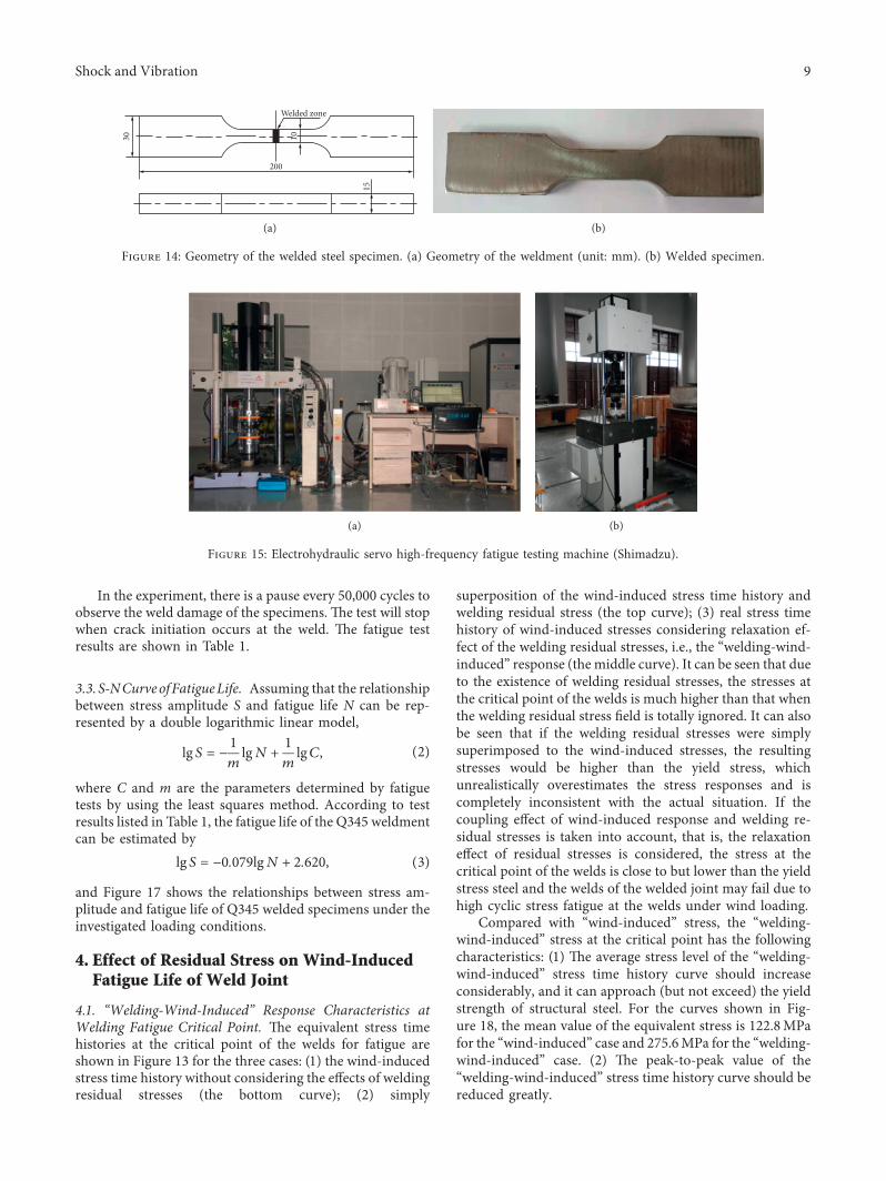
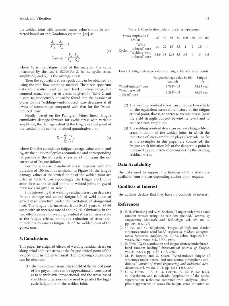