effective erosion control plans · 6/18/2013 1 effective erosion control plans bruce hasbrouck, cep...
TRANSCRIPT

6/18/2013
1
EFFECTIVE EROSION CONTROL PLANS
EFFECTIVE EROSION CONTROL PLANS
Bruce Hasbrouck, CEP
Faller, Davis & Associates, Inc.
&
Larry Ritchie, FDOT
TRANSPORTATION PROJECTS
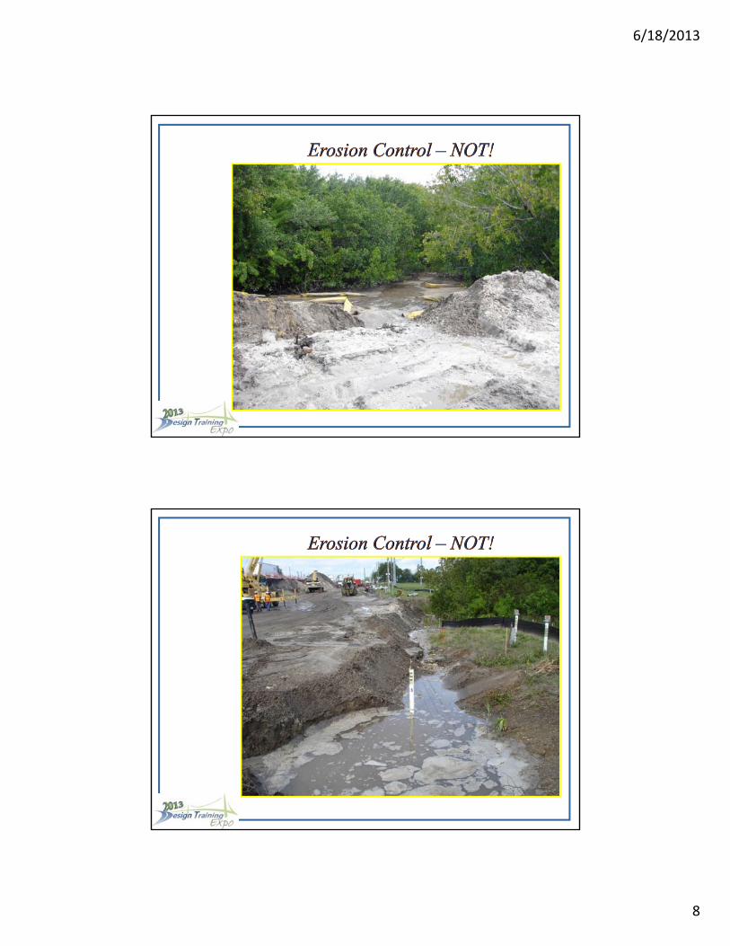
Most FDOT projects require development of Stormwater Pollution Prevention Plan sheets and notes.
6/18/2013
2
DESIGNERS!!!
Designers are the first and sometimes only people who review plans and provide erosion prevention and sediment control (E & SC) materials and methods for a project.
A designer’s knowledge of the project area and available E & SC tools are critical in developing a plan to help prevent erosion and control discharge of sediment and turbid water.
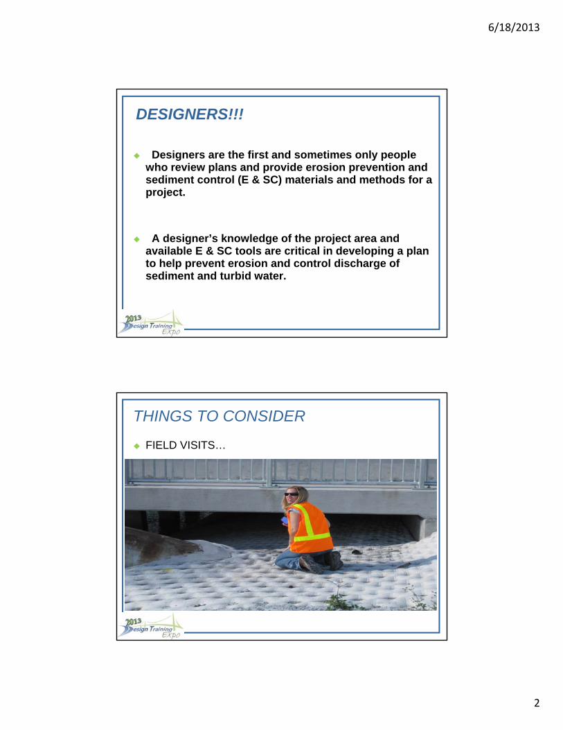
THINGS TO CONSIDER
FIELD VISITS…
6/18/2013
3
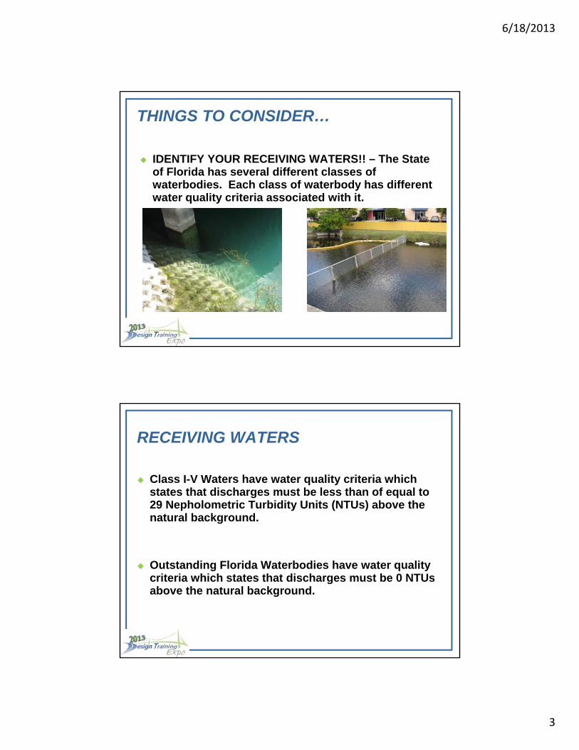
THINGS TO CONSIDER…
IDENTIFY YOUR RECEIVING WATERS!! – The State of Florida has several different classes of waterbodies. Each class of waterbody has different water quality criteria associated with it.
RECEIVING WATERS
Class I-V Waters have water quality criteria which states that discharges must be less than of equal to 29 Nepholometric Turbidity Units (NTUs) above the natural background.
Outstanding Florida Waterbodies have water quality criteria which states that discharges must be 0 NTUs above the natural background.

6/18/2013
4
RECEIVING WATERS
The Florida Department of Environmental Protection maintains a list of all waterbodies along with their classifications. This list can be found here:
http://www.dep.state.fl.us/water/wqssp/index.htm
CHEMICAL TREATMENT
Section 104-6.4.10 Chemical Treatment – Provides language for the use of Polyacrylamides(PAM) and Aluminum Sulfate on FDOT construction projects provided the contractor can produce the toxicity testing information found in the E & SC Manual.
Currently, the Department has established two separate pay items for Chemical Treatment:
104-19 Chemical Treatment, Per square yard
104-20 Chemical Treatment, Per each
6/18/2013
5
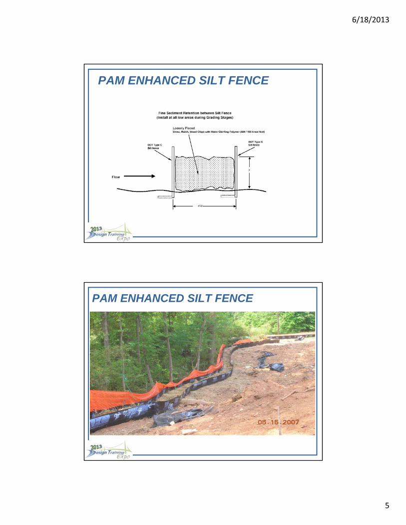
PAM ENHANCED SILT FENCE
PAM ENHANCED SILT FENCE
6/18/2013
6
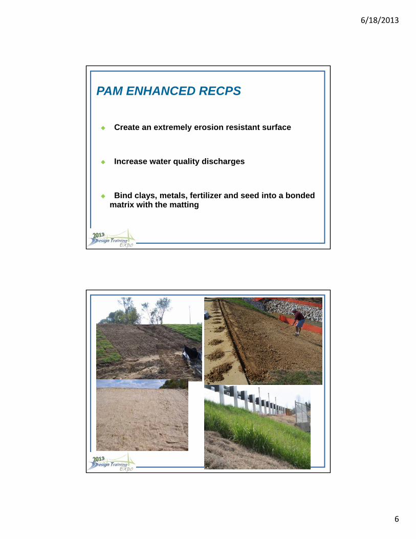
Create an extremely erosion resistant surface
Increase water quality discharges
Bind clays, metals, fertilizer and seed into a bonded matrix with the matting
PAM ENHANCED RECPS

6/18/2013
7
DEVELOPMENTAL SPECIFICATION
Lump Sum payment for all aspects of erosion and sediment control.
References the Designer and Reviewer Manual as the guidance document for designing erosion and sediment control plans.
DEVELOPMENTAL SPEC.
Requires the Contractor’s Engineer to submit his plan for review to FDEP or the WMD’s before he can start work.
Contains turbidity sampling criteria for each rain event measuring 0.50 inches or greater.
Requires the Specialty Engineer to make field visits in conjunction with the staging of a construction project to ensure that the plan he developed is being correctly installed in the field.
6/18/2013
8
6/18/2013
9
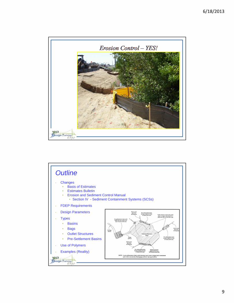
Outline• Changes
• Basis of Estimates• Estimates Bulletin• Erosion and Sediment Control Manual
• Section IV - Sediment Containment Systems (SCSs)
• FDEP Requirements
• Design Parameters
• Types
• Basins
• Bags
• Outlet Structures
• Pre-Settlement Basins
• Use of Polymers
• Examples (Reality)
6/18/2013
10
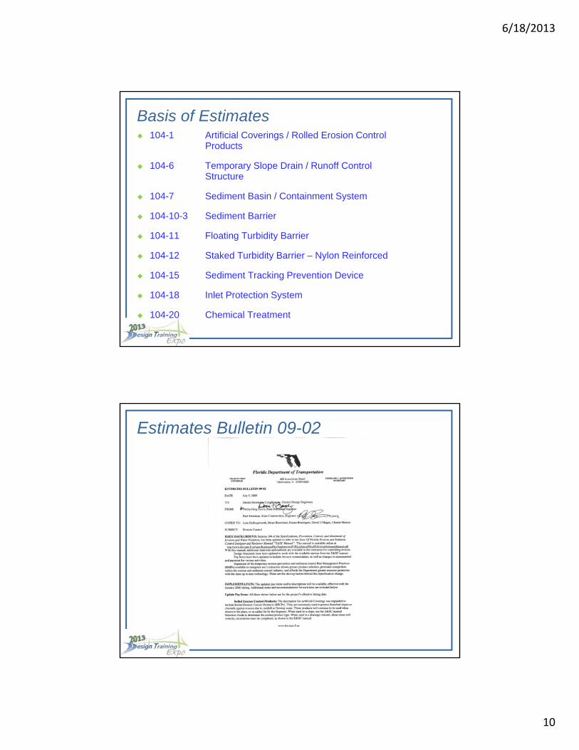
Basis of Estimates 104-1 Artificial Coverings / Rolled Erosion Control
Products
104-6 Temporary Slope Drain / Runoff Control Structure
104-7 Sediment Basin / Containment System
104-10-3 Sediment Barrier
104-11 Floating Turbidity Barrier
104-12 Staked Turbidity Barrier – Nylon Reinforced
104-15 Sediment Tracking Prevention Device
104-18 Inlet Protection System
104-20 Chemical Treatment
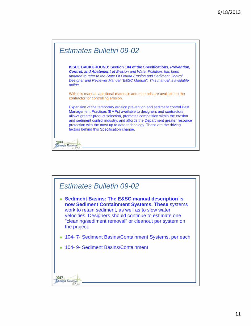
Estimates Bulletin 09-02
6/18/2013
11
ISSUE BACKGROUND: Section 104 of the Specifications, Prevention, Control, and Abatement of Erosion and Water Pollution, has been updated to refer to the State Of Florida Erosion and Sediment Control Designer and Reviewer Manual "E&SC Manual". This manual is available online.
With this manual, additional materials and methods are available to the contractor for controlling erosion.
Expansion of the temporary erosion prevention and sediment control Best Management Practices (BMPs) available to designers and contractors allows greater product selection, promotes competition within the erosion and sediment control industry, and affords the Department greater resource protection with the most up to date technology. These are the driving factors behind this Specification change.
Estimates Bulletin 09-02
Sediment Basins: The E&SC manual description is now Sediment Containment Systems. These systems work to retain sediment, as well as to slow water velocities. Designers should continue to estimate one "cleaning/sediment removal" or cleanout per system on the project. The pay item description for both the system and the cleanout will be updated on or before January 1, 2010.
104- 7- Sediment Basins/Containment Systems, per each104- 9- Sediment Basins/Containment System Cleanout, per each.
Estimates Bulletin 09-02
Sediment Basins: The E&SC manual description is now Sediment Containment Systems. These systems work to retain sediment, as well as to slow water velocities. Designers should continue to estimate one "cleaning/sediment removal" or cleanout per system on the project.
104- 7- Sediment Basins/Containment Systems, per each
104- 9- Sediment Basins/Containment System Cleanout, per each.

6/18/2013
12
E&SC Manual
6/18/2013
13
FDEP Manual:
“Always remember that the rules are performance based—i.e., the measures used at a construction site must effectively control erosion and prevent sedimentation from reaching a regulated receiving water for the site to be in compliance.”
“The implementation of BMPs according to this manual is no guarantee of success, nor is it a constraint to prevent the use of other more efficient or cost-effective measures.”
NPDES Generic Permit –SWPPP Part V, D. Contents ofPlan,
a. Erosion and Sediment Controls
(3) Sediment Basins
(a) For drainage basins with 10 or more disturbed acres atone time, a temporary (or permanent) sediment basinproviding 3,600 cubic feet of storage per acre drained, orequivalent control measures, shall be provided whereattainable until final stabilization.f the site.
6/18/2013
14
Sediment Containment Systems (SCSs) are:
• barriers having hydraulic controls that function by modifying the storm-runoff hydrograph and slowing water velocities.
• allows for the deposition of larger suspended particles by gravity.
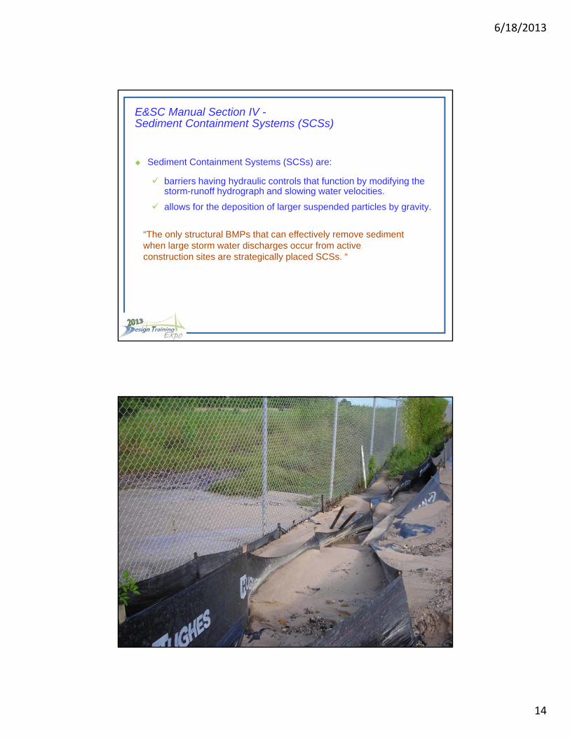
“The only structural BMPs that can effectively remove sediment when large storm water discharges occur from active construction sites are strategically placed SCSs. “
E&SC Manual Section IV -Sediment Containment Systems (SCSs)
Sediment Containment Systems (SCSs) are:
barriers having hydraulic controls that function by modifying the storm-runoff hydrograph and slowing water velocities.
allows for the deposition of larger suspended particles by gravity.

6/18/2013
15
According to the Manual, “Designers must include properly designed SCSs as an integral part of their E&SC plan.”
More importantly, the development of effective SCSs must be based upon capturing design size particles.
According to the Manual, “Designers must include properly designed SCSs as an integral part of their E&SC plan.”
More importantly, the development of effective SCSs must be based upon capturing design size particles.

6/18/2013
16
Deposition of sediment in an SCS is dependent upon many different parameters, including:
• Mass of the suspended particles falling through contained waters
• Surface area and containment storage volume for incoming runoff waters
• Sufficient flow path lengths within the containment system
• Uniform flow zones within the storage volume
• Discharge rates of water out of the containment system
6/18/2013
17
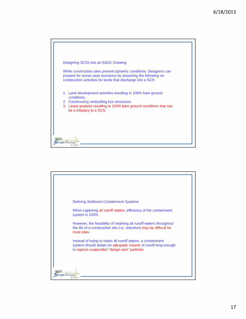
Designing SCSs into an E&SC Drawing
While construction sites present dynamic conditions, Designers can prepare for worse case scenarios by assuming the following on construction activities for lands that discharge into a SCS:
1. Land development activities resulting in 100% bare ground conditions.
2. Constructing vertical/big box structures. 3. Linear projects resulting in 100% bare ground conditions that can
be a tributary to a SCS.
Defining Sediment Containment Systems
When capturing all runoff waters, efficiency of the containment system is 100%. However, the feasibility of retaining all runoff waters throughout the life of a construction site (i.e. retention) may be difficult for most sites. Instead of trying to retain all runoff waters, a containment system should detain an adequate volume of runoff long enough to capture suspended “design size” particles.
Defining Sediment Containment Systems
When capturing all runoff waters, efficiency of the containment system is 100%.
However, the feasibility of retaining all runoff waters throughout the life of a construction site (i.e. retention) may be difficult for most sites.
Instead of trying to retain all runoff waters, a containment system should detain an adequate volume of runoff long enough to capture suspended “design size” particles.

6/18/2013
18
Sediment Containment System Classifications
Type-1 Sediment Containment System Design-Size Particle 0.075 mm (very fine sand and clays)
Type-2 Sediment Containment System 0.075 mm < Design-Size Particle 0.41 mm (between very fine sand and medium sands)
Type-3 Sediment Containment System Design-Size Particle > 0.41 mm (larger than medium sands)
Sediment Containment System Classifications
Type-1 Sediment Containment System Design-Size Particle <0.075 mm (very fine sand and clays)
Type-2 Sediment Containment System Design-Size Particle 0.075 - 0.41 mm (between very fine sand and medium sands)
Type-3 Sediment Containment System Design-Size Particle > 0.41 mm (larger than medium sands)

6/18/2013
19
Type-1 Sediment Containment System
A Type-1 SCS will require development of a structure to capture the maximum possible number of coarse silt and smaller suspended particles. Since particles of this size settle very slowly without flocculation, large storage volume Type-1 SCSs require long flow-path lengths, large containment volumes, and controlled discharges.
Usually, development of Type-1 SCSs requires the expertise of a professional having skills in proper design of embankments, outlet structures, and spillways.
6/18/2013
20
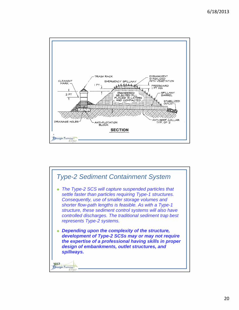
Type-2 Sediment Containment System
The Type-2 SCS will capture suspended particles that settle faster than particles requiring Type-1 structures. Consequently, use of smaller storage volumes and shorter flow-path lengths is feasible. As with a Type-1 structure, these sediment control systems will also have controlled discharges. The traditional sediment trap best represents Type-2 systems.
Depending upon the complexity of the structure, development of Type-2 SCSs may or may not require the expertise of a professional having skills in proper design of embankments, outlet structures, and spillways.
6/18/2013
21
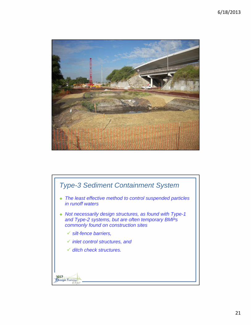
Type-3 Sediment Containment System
The least effective methods to control suspended particles in runoff waters are Type-3 SCSs. These are not necessarily design structures, as found with Type-1 and Type-2 systems, but are often temporary BMPs commonly found on construction sites such as silt-fence barriers, inlet control structures, and ditch check structures. Whenever significant runoff occurs, all Type-3 systems have very low effectiveness to control suspended particles without some additional treatment (e.g. adding a polymer). However, when runoff is small and adequate maintenance exists, the Type-3 sediment control systems may be effective in removing larger diameter suspended particles. Extensive information on Type-3 systems appears in Section V.
Type-3 Sediment Containment System
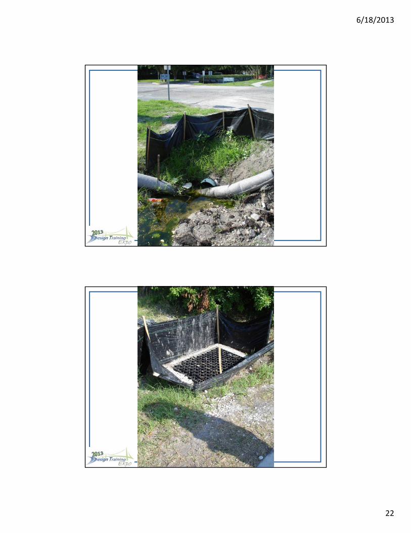
The least effective method to control suspended particles in runoff waters
Not necessarily design structures, as found with Type-1 and Type-2 systems, but are often temporary BMPs commonly found on construction sites
silt-fence barriers,
inlet control structures, and
ditch check structures.
6/18/2013
22
6/18/2013
23
Effectiveness of Sediment Containment Systems
Field studies were conducted by EPA (1976) to characterize containment systems and to evaluate their effectiveness for trapping sediment.
It was concluded from these studies that efficiencies of sediment containment systems could be increased by:
• Using techniques that reduce inflow energy
• Allowing sufficient travel time for design-size particles to fall through the water
• Preventing re-suspension of particles
Effectiveness of Sediment Containment Systems
Field studies were conducted by EPA to characterize containment systems and to evaluate their effectiveness for trapping sediment.
It was concluded from these studies that efficiencies of sediment containment systems could be increased by:
• Using techniques that reduce inflow energy
• Allowing sufficient travel time for design-size particles to fall through the water
• Preventing re-suspension of particles
DEWATERING ACTIVITIES
Dewatering operations are an important component in the construction process and receive special attention from the local water management agencies. Regulators are especially concerned with the protection of wetlands from drawdown effects and protecting the receiving water body from sedimentation and capacity limitations.
Dewatering Activities
Dewatering operations are an important component in the construction process and receive special attention from the local water management agencies.
Regulators are especially concerned with the protection of wetlands from drawdown effects and protecting the receiving water body from sedimentation and capacity limitations.
6/18/2013
24
Types of Dewatering Methods
• Rim Ditching • Most Common• Least Expensive• Dirtiest Water
• Sock Pipe/Horizontal Wells • More Expensive• Cleaner Water
• Well Point Systems • Most Expensive• Cleanest Water
Types of Dewatering Methods
• Rim Ditching
• Most Common
• Least Expensive
• Dirtiest Water
• Sock Pipe/Horizontal Wells
• More Expensive
• Cleaner Water
• Well Point Systems
• Most Expensive
• Cleanest Water
Turbidity Monitoring for Off-site Discharge
When dewatering operations consist of off-site discharge, the contractor must ensure the effluent meets state water quality standards.
The standards for discharging water into a receiving body cannot exceed 29 nephelometric turbidity units (NTUs) above background. (Zero NTUs for OFWs)
Samples of the effluent should be taken at the discharge point into the receiving body. For best results, samples should be taken 2 times a day, at least 4 hours apart.

6/18/2013
25
Using SCSs for Dewatering
Dewatering will usually involve pumping water into a temporary containment system to ensure proper settlement of suspended particles. The equations found in Table IV-2 can assist Designers in development of a small SCS needed for these dewatering activities. Unfortunately, it is not known what the diameter of suspended particles will occur during pumping activities. However, Designers can provide preliminary assessments and recommendations using the following assumptions:
• The design size particle will be 0.02 mm
• The discharge rate of water out of the SCS will equal the pumping rate
• The minimum volume of contained water will be that found for a Type-2 system
Using SCSs for Dewatering
Usually involves pumping water into a SCSs to ensure proper settlement of suspended particles.
Equations found in Table IV-2 can assist Designers in development of a small SCS needed for these dewatering activities.
Designers can provide preliminary assessments and recommendations using the following assumptions:
• The design size particle will be 0.02 mm
• The discharge rate of water out of the SCS will equal the pumping rate
• The minimum volume of contained water will be that found for a Type-2 system
6/18/2013
26
Pre-Sedimentation Basins
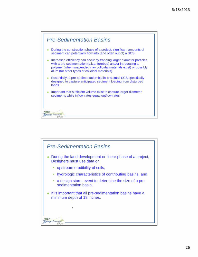
During the construction phase of a project, significant amounts of sediment can potentially flow into (and often out of) a SCS. Increased efficiency can occur by trapping larger diameter particles with a pre-sedimentation (a.k.a. forebay) and/or introducing a polymer (when suspended clay colloidal materials exist) or possibly alum (for other types of colloidal materials).
Essentially, a pre-sedimentation basin is a small SCS specifically designed to capture anticipated sediment loading from disturbed lands. However, it is important that sufficient volume exist to capture larger diameter sediments while inflows equal outflows.
Pre-Sedimentation Basins
During the construction phase of a project, significant amounts of sediment can potentially flow into (and often out of) a SCS.
Increased efficiency can occur by trapping larger diameter particles with a pre-sedimentation (a.k.a. forebay) and/or introducing a polymer (when suspended clay colloidal materials exist) or possibly alum (for other types of colloidal materials).
Essentially, a pre-sedimentation basin is a small SCS specifically designed to capture anticipated sediment loading from disturbed lands.
Important that sufficient volume exist to capture larger diameter sediments while inflow rates equal outflow rates.
During the land development or linear phase of a project, Designers must use data on:
• upstream erodibility of soils,
• hydrologic characteristics of contributing basins, and
• a design storm event to determine the size of a pre-sedimentationbasin.
It is important that all pre-sedimentation basins have a minimum depth of 18 inches..
Pre-Sedimentation Basins
During the land development or linear phase of a project, Designers must use data on:
• upstream erodibility of soils,
• hydrologic characteristics of contributing basins, and
• a design storm event to determine the size of a pre-sedimentation basin.
It is important that all pre-sedimentation basins have a minimum depth of 18 inches.
6/18/2013
27
Barriers for Pre-Sedimentation Basins
A riprap barrier at the discharge end of a pre-sedimentation basin provides a simple method to detain runoff waters and still allow for the deposition of larger sized suspended particles while ensuring inflow values equal outflow values.
Use of these barriers is more commonly for “in-line” basins placed within drainage channels. It is important that sufficient spillway width be available to ensure flood flow conditions can occur without damaging the structure.
Another type of barrier consists of material placed in front of a culvert in a manner that allows for pond development and conveyance of inflow waters from drainage swales or upstream storm sewer systems. It is important that proper design and installation occur to ensure outflow values are not less than inflow values.
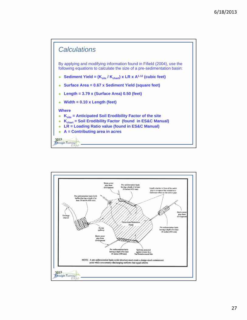
Calculations
By applying and modifying information found in Fifield (2004), use the following equations to calculate the size of a pre-sedimentation basin:
Sediment Yield = (Ksite / Kchart) x LR x A1.12 (cubic feet)
Surface Area = 0.67 x Sediment Yield (square feet)
Length = 3.79 x (Surface Area) 0.50 (feet)
Width = 0.10 x Length (feet)
Where Ksite = Anticipated Soil Erodibility Factor of the site Kchart = Soil Erodibility Factor (found in ES&C Manual) LR = Loading Ratio value (found in ES&C Manual) A = Contributing area in acres
6/18/2013
28
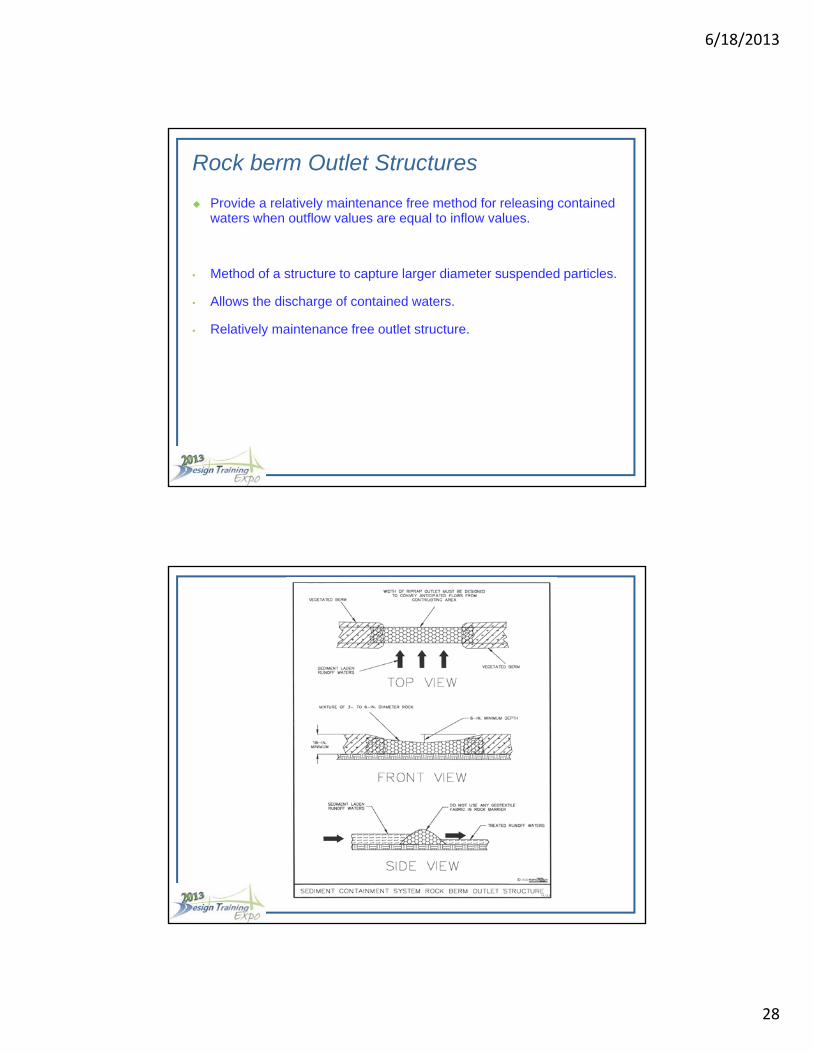
Rock Berm Outlet Structures
• Provide a relatively maintenance free method for releasing containedwaters when outflow values are equal to inflow values.
• Method of a structure to capture larger diameter suspended particles.
• Allows the discharge of contained waters.
• Provides development of small wetlands after grading is done.
• Relatively maintenance free outlet structure.
Rock berm Outlet Structures
Provide a relatively maintenance free method for releasing contained waters when outflow values are equal to inflow values.
• Method of a structure to capture larger diameter suspended particles.
• Allows the discharge of contained waters.
• Relatively maintenance free outlet structure.

6/18/2013
29
6/18/2013
30
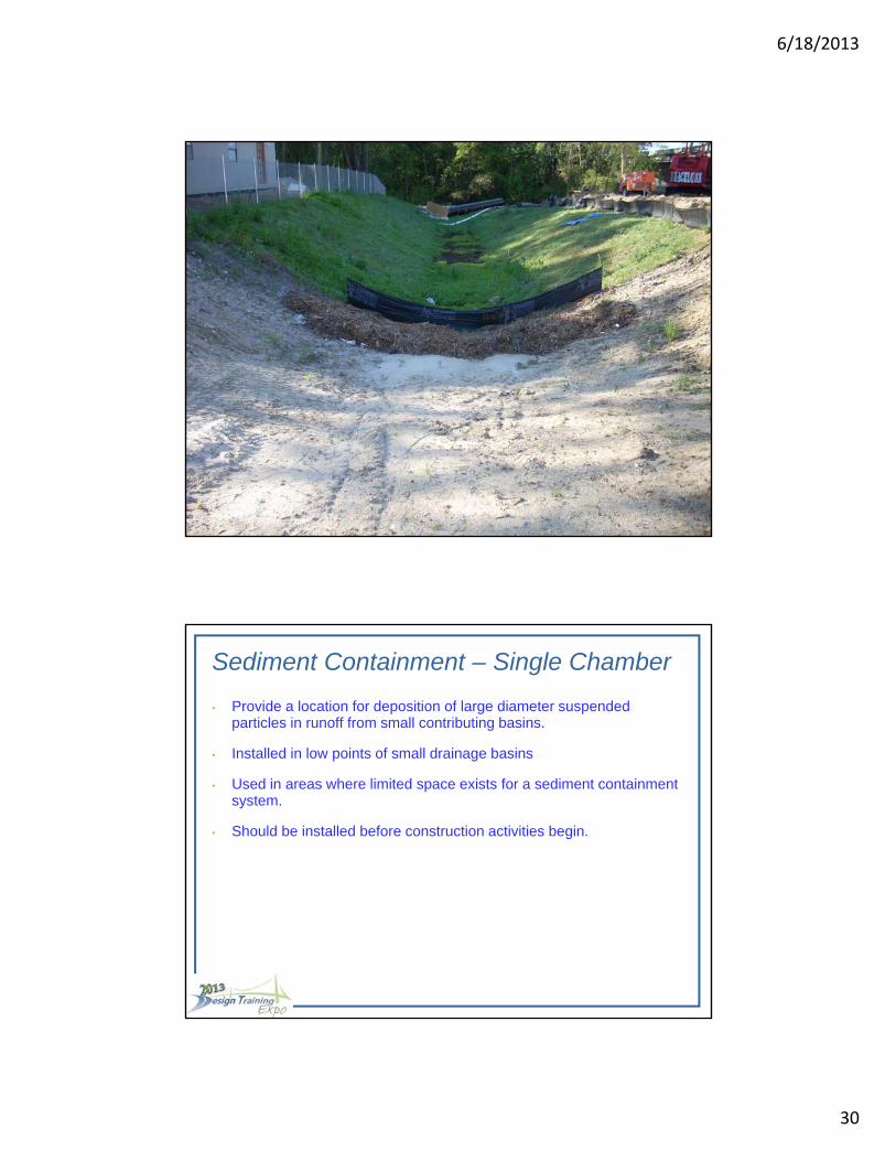
Sediment Containment Single Chamber
• Provide a location for deposition of large diameter suspended particles inrunoff from small contributing basins.
• Installed in low points of small drainage basins
• Used in areas where limited space exists for a sediment containmentsystem.
• Should be installed before construction activities begin.
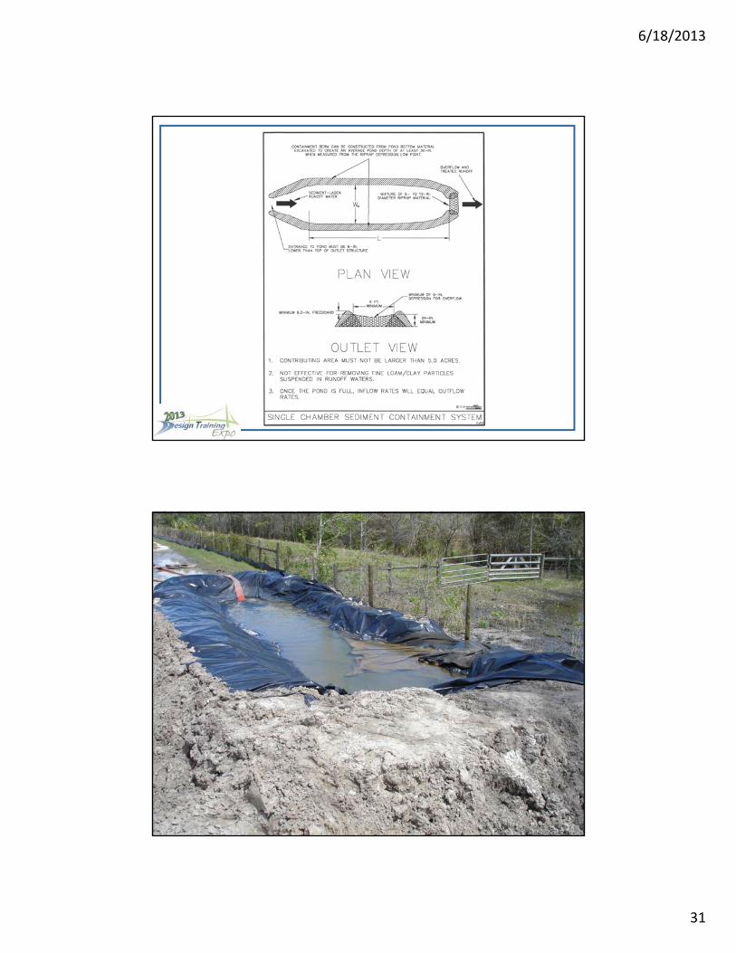
Sediment Containment – Single Chamber
• Provide a location for deposition of large diameter suspended particles in runoff from small contributing basins.
• Installed in low points of small drainage basins
• Used in areas where limited space exists for a sediment containment system.
• Should be installed before construction activities begin.
6/18/2013
31
6/18/2013
32
Sediment Containment Double Chamber
• Same parameters as Single Chamber
• The length parameter is to be reduced by 50% (i.e., Lfinal = ½ x Length) as calculated by the Designer from equations found in the pre-sedimentation basin section.
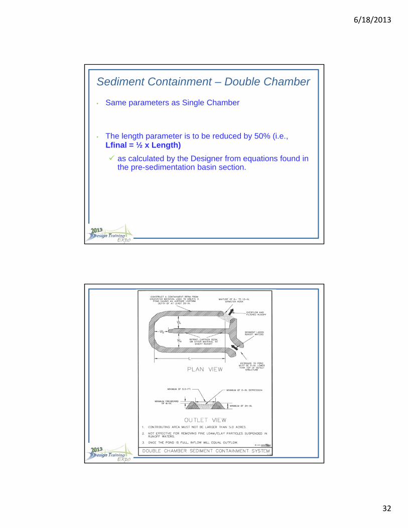
Sediment Containment – Double Chamber
• Same parameters as Single Chamber
• The length parameter is to be reduced by 50% (i.e., Lfinal = ½ x Length)
as calculated by the Designer from equations found in the pre-sedimentation basin section.
6/18/2013
33
Sizing Sediment Containment Systems
For drainage basins with 10 or more disturbed acres at one time, a temporary (or permanent) sediment basin providing 3,600 cubic feet of storage per acre drained, or equivalent control measures, shall be provided where attainable until final stabilization.
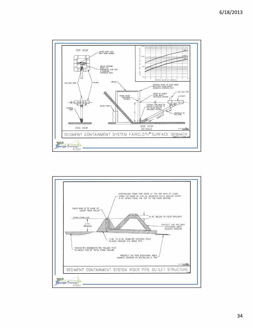
SCS Outlet Structures
An important element of effective sediment containment systems is the outlet structure. These are required for containing runoff waters from a structure and can include the following systems:
• Surface Skimmers
• Perforated Riser Pipes
6/18/2013
34
6/18/2013
35
Sediment Containment System for Barrier to Culvert
• To reduce inflow velocity so that deposition of suspended particles foundin runoff can occur upstream of the barrier.
• Installed on the upstream side of culverts.
• Installed as part of total sediment containment system.
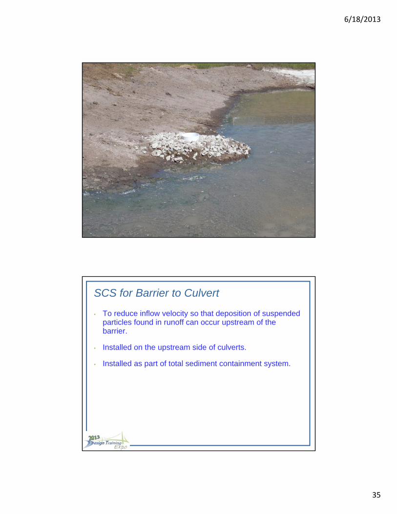
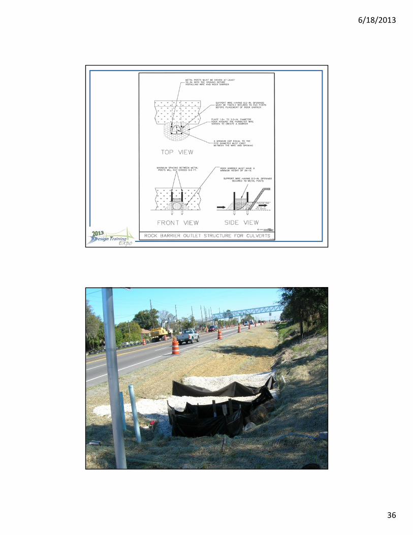
SCS for Barrier to Culvert
• To reduce inflow velocity so that deposition of suspended particles found in runoff can occur upstream of the barrier.
• Installed on the upstream side of culverts.
• Installed as part of total sediment containment system.
6/18/2013
36

6/18/2013
37
Sediment Containment Filter Bag
• To remove larger diameter size particles from sediment-laden waters byfiltration.
• Commonly used to remove water collected behind cofferdams, kelly wells,and dewatering activities.
• Maintenance is important; replace frequently, i.e. weekly.
Sediment Containment Filter Bag
• To remove larger diameter size particles from sediment-laden waters by filtration.
• Commonly used to remove water collected behind cofferdams, kelly wells, and dewatering activities.
• Maintenance is important; replace frequently, i.e. weekly.

6/18/2013
38

6/18/2013
39
Use of Polymers or Alum
When polymers or alum are added in correct amounts to sediment-laden waters, suspended colloidal particles combine resulting in an increased mass that is subject to acceleration by gravity through the water column.
However, Designers need to be aware that polymers or alum may be detrimental to aquatic life if introduced in inappropriate quantities or not properly selected for site conditions.
Use of Polymers or Alum
When polymers are added in correct amounts to sediment-laden waters, suspended colloidal particles combine resulting in an increased mass that is subject to acceleration by gravity through the water column.
However, Designers need to be aware that polymers or alum may be detrimental to aquatic life if introduced in inappropriate quantities or not properly selected for site conditions.
Alum is not to be included in the plans without specific approval by Larry Ritchie in the State Construction Office.
Step 2: Calculate the Temporary Sedimentation Basin Parameters.
• Surface Area = 0.67 x 1,185 = 794 square feet
• Length = 3.79 x (794) 0.5 = 106 feet
• Width = 0.10 x 106 = 11 feet
• Depth = 1.5 feet
Thus, when sufficient polymer is continually introduced into runoff waters discharging from 5.0 acres of disturbed lands, a pre-sedimentation basin about 106 feet long, 11 feet wide, and 18 inches deep is required. It may be adequate to place the SCS in line with the drainage swale to capture anticipated sediment loads caused by a 2.75-inch (and smaller) storm event.
Determine the Parameters of a SCS
Step 1: Determine the Sediment Yield.
• When 2.75 inches of rain falls on a bare ground slope of 2.50%,
- then LR = 210 cu. ft/ac1.12 (from Chart)
• Sediment Yield = (Ksite / Kchart) x LR x A1.12 (cubic feet)
• Sediment Yield = (0.40 / 0.43) x 210 x 5.01.12 = 1,185 cubic feet
6/18/2013
40
Basis of Estimate
State-Wide Average
Tampa Airport Interchanges Project
I-4 / Crosstown Connector
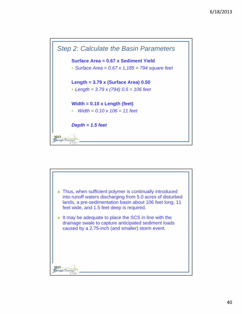
Step 2: Calculate the Basin Parameters
Surface Area = 0.67 x Sediment Yield
• Surface Area = 0.67 x 1,185 = 794 square feet
Length = 3.79 x (Surface Area) 0.50
• Length = 3.79 x (794) 0.5 = 106 feet
Width = 0.10 x Length (feet)
• Width = 0.10 x 106 = 11 feet
Depth = 1.5 feet
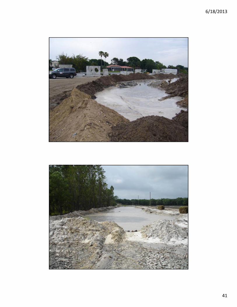
Thus, when sufficient polymer is continually introduced into runoff waters discharging from 5.0 acres of disturbed lands, a pre-sedimentation basin about 106 feet long, 11 feet wide, and 1.5 feet deep is required.
It may be adequate to place the SCS in line with the drainage swale to capture anticipated sediment loads caused by a 2.75-inch (and smaller) storm event.
6/18/2013
41
6/18/2013
42

6/18/2013
43
6/18/2013
44

6/18/2013
45
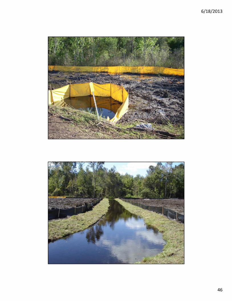
Flow Throughs
6/18/2013
46
6/18/2013
47
6/18/2013
48

6/18/2013
49

6/18/2013
50
6/18/2013
51
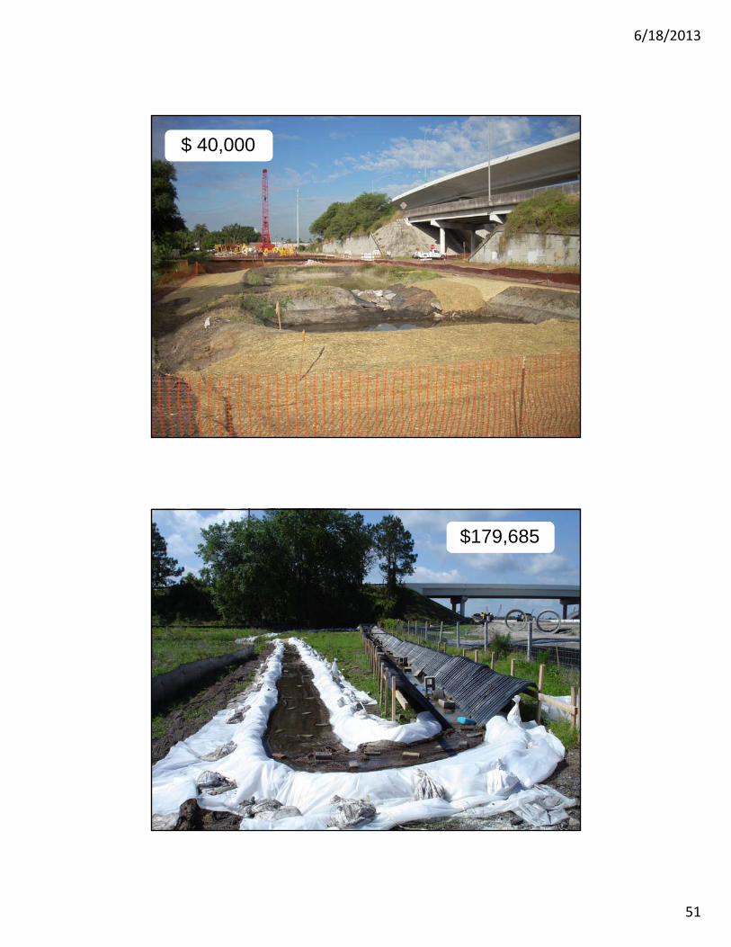
$ 40,000
$179,685

6/18/2013
52
$345,629
Questions?