effective heat installation guid
TRANSCRIPT

Effective Heat Glass Works, Installation Guide
Table Of Contents
Equipment and Materials Check List
Multimeter
Setting the Crucible
Element Preparation and Installation
Element wiring
Door Assembly
Maintenance
Crucible Change
Trouble shooting
Recieving And Unpalleting the Furnace 1
2
4
3
6
5
8
7
Unpacking:
Wiring
Assembly
Upkeep
11
12
13
Control Unit Wiring 10
Cooling system
Thermocouple wiring 9

Effective Heat Glass Works, Installation Guide
1 Recieving and Unpalleting the FurnaceWhen moving the furnace a 6000# rated forklift is required. A bobcat or tractor with forks will not suffice, the furnace is too heavy for those machines.
1. place the furnace where there is ample arrom to remove the pallet from underneath the furnace.
2. undo the shipping straps and place them into the box provided for return shipping.
4. slide the forks in all the way, tilt back the forklift a little, lift up, remove the pallet, flip the wheels down and set the furnace down and roll it into place.
5. Get a drill and a #2 phillips head, take the crate apart. Lift the control stand with the forks inderneath the crossbars in the middle above the transformer.
3. Align the forks of the forklift inbetween the wood stickers. Be sure to clear the riser bolts as well. The riser bolts are underneath the furnace.

Effective Heat Glass Works, Installation Guide
1Equipment and Materials Checklist
2
Furnace
Control Unit
Door and door frame
Elements
Multimeter
10 mm wrenches
Dip lag ( fiberglass cloth for top of furnace)
Hardware for Straps (5/16” bolts, nuts, washers, lock washers)
Straps and Clamps (for elements)
Element Coolers
Element Bricks
Thermocouple (attached to control unit)
Blower unit ( attached to control unit)
No-alox
Door switch ( attached to control unit)
Effective Heat Glass Works, Installation Guide
3 Setting the Crucible
To set the crucible you must first remove the packing material inside the furnace to place the cruciblle. Lower the riser bolts underneath the furn ace for stability.
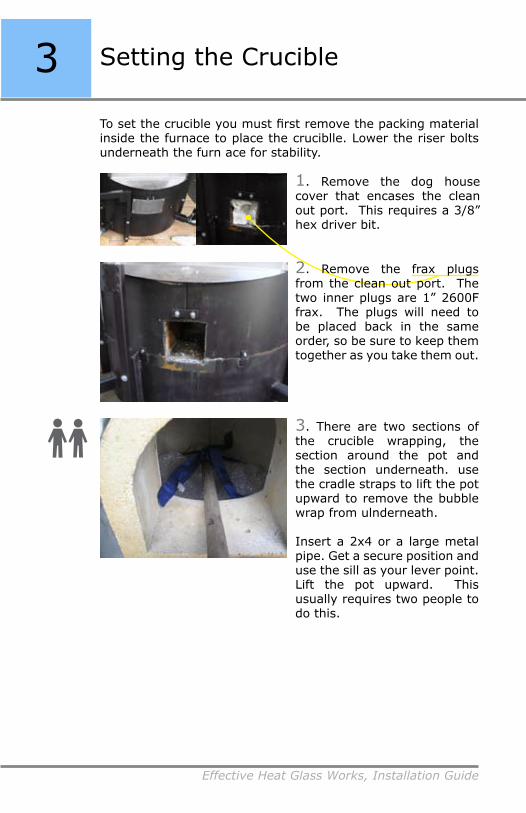
1. Remove the dog house cover that encases the clean out port. This requires a 3/8” hex driver bit.
3. There are two sections of the crucible wrapping, the section around the pot and the section underneath. use the cradle straps to lift the pot upward to remove the bubble wrap from ulnderneath.
Insert a 2x4 or a large metal pipe. Get a secure position and use the sill as your lever point. Lift the pot upward. This usually requires two people to do this.
2. Remove the frax plugs from the clean out port. The two inner plugs are 1” 2600F frax. The plugs will need to be placed back in the same order, so be sure to keep them together as you take them out.

Effective Heat Glass Works, Installation Guide
3:Setting the Crucible
4. With the crucible elevated, use the clean out port to begin pulling out the bubble wrap from undernieth. It can be a struggle sometimes to pull out the bubble wrap. This also may require two people
5. Lower the crucible on the floor of the furnace.
* If the crucible height is different than you like you can place a brick underneath the pot. Use a cedramic fire brick. (IFB are too soft for the weight of the crucible). Place the brick or bricks, securely underneath the pot to stabilize it.

Effective Heat Glass Works, Installation Guide
3 :Setting the Crucible
6. Next, reach in through the gathering port and slice away the lifting straps using a razor knife.
The bubble wrap is wrapped around the sides of the crucible and seccured with a piece of tape. Cut the tape to pull the bubble wrap out. The tape is just below the edge of the crucible on the outside.
Begin pullling the bubble wrap straight up first before pulling out. This will make it a bit easier.
7. Once the bubble wrap is out, check to see that there is equal spacing from the walls, around the crucible. wiggle the pot to see if it is unstable. If so, just use a bit of playground sand to keep the crucible from rocking.
8. After the crucible is set, return the frax plugs to the clean out port in their original order and reattach the dog house cover.

Effective Heat Glass Works, Installation Guide
4Door Assembly
1. Slide the door frames together making sure the allthread is is placed throught the center hole on each frame.
This allhtread controlls the up down adjustment but is only applicable during installation. It becomes a static measurement once set.
The door track is a simple two track system. The top track is skewed outward from the furnace to allow the door to release instead of scrape alon the face. The lower door track is adjustable for gathering port buildup.
The door itself is adjustable on four bolts that hold the door to the door frame. These four posts allow you to adjust the seal on your door.

Effective Heat Glass Works, Installation Guide
42. Carefully pick the door up and set it on the track. Use a crescent wrench, or a 5/8” wrench to adjust the height of the door.
Now is the time to adgust the allthread so the door is alligned with the gathering port.
3. Once the door is on and adjusted take the door switch controller thats wired to your control panel and attach it to the mounting plate, located on the top door track.
The controller will turn the furnace on when the door is shut and turn it off when it is open.
that is why it is important to make sure that the toggle switch has fully clicked over. When the door is fully shut, the toggle should catch the bolt from the door castor and you should hear a little click.
:Door Assembly

Effective Heat Glass Works, Installation Guide
4:Door Assembly
5. Some of the furnace models leave the door tracks at dangerous heights. To solve this just cut a tennis ball or a racquet ball. Cut just one slit about 1/3 of the ball and slip the ball over the end of each track.
4. The allthread for the lower doortrack adjustment should be sitting in the lower door track upright, just below the door.
The lower door track can be adjusted outward, in order to swing door slightly away from the gathering port as it slides open. This Keeps the two faces from scraping as the door slides open and closed. It will also help with the buildup of stringers.

Effective Heat Glass Works, Installation Guide
5 Multimeter
Taking Measurments:There are two different ways to take a measurement:
1. Induction Clamp:The induction clamp at the top of the meter. To use it, clamp around the wire where testing is needed and pull the trigger on the side.
*Only clamp insulated wires, do not clamp bare wires. Make sure that the clamp is secure to get an accurate reading.
2. Probes:Use the two probes to touch the testing sites where testing is desired.
Most new meters have plugs inserted in to the probe connectors. Remove these and plug the probes into the appropriately colored slots at the bottom.
*A bare wire or screw terminal is necessary to achieve a reading.
Measurements will be displayed on the digital screen. “OL” (off line) it a default reading that appears when no measurement is present.
The multimeter is the most important tool to keeping your furnace running efficiently. This is how you will measure different electrical properties.
*Take extreme caution when taking electrical measurements.

Effective Heat Glass Works, Installation Guide
5:Multimeter
Types of Measurments:There are three main measurement settings that will be relevant for this product:
(Volts) (Amperage) (Continuity/Ohms/Resistance)
1. V 2. A 3. Ω/
*Notice that there are two different measurment settings for V and A (V and A ) These settings use a different type of curent and are not applicable to our products. All measurements taken with this meter will be in AC mode (alternating current), indicated by the .
You can select the type of measurement you would like to take by turning the dial to the appropriate icon.
When measuring V or Ω use the Probes.
When Measuring A use the Induction Clamp
You can also measure Ω with an auditory signal by turning the dial to the sound icon.
The only two buttons you will use from time to time are the sensitivity button ( )and the backlight button(for dark areas).

Effective Heat Glass Works, Installation Guide
5
1. To begin, remove the element boxes from the crate. Test each element for continuity before opening the element boxes by placing the probes to the terminal ends. Use the sound symbol on your multi meter as shown in the earlier section.
2. Once the contunuity is established, clear a large work area to assemble the heater components as shown below. Along with the heaters, you will need:
• tape measure • 10 mm wrenches that are supplied• a razor knife• the element bricks• the ceramic element clamps• a chopstick or BBQ skewer• and the ceramic fiber that is provided.
Element Prep and Installation
You are now ready to prep the elements for assembly and installation. Each element assembly will be placed in the crown.
Element Assembly

Effective Heat Glass Works, Installation Guide
6:Element Prep and Installation
3. The elements are very fragile, but if handled correctly they will last for years. To handle the elements pick them up by the wooden stability blocks.
Set the element on the table, place one side of the element on the table. The terminal shank is what you want to lay down, the heater portion should not touch the table. Then set the other side down gently.
4. To place the element in the brick you must remove one of the wooden blocks. Take your razor knife and carefully slice the tape holding the block to the element. Now gently flip the element over and slice the other side. be careful not to stress the element.
*Do not cut the tape on the other wooden block close to the heater portion. If you do cut the tape, replace it promptly. do not handle the element without the wooden block in place.
*Only work on one element at a time, this reduces the chance of breakage
ilustration

Effective Heat Glass Works, Installation Guide
6 :Element Prep and Installation
Effective Heat Glass Works, Installation Guide
6:Element Prep and Installation
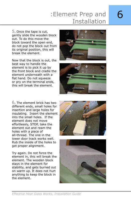
5. Once the tape is cut, gently slide the wooden block out. To do this move the block toward the open end, do not pop the block out from its original position, this will break the element.
Now that the block is out, the best way to handle the element is to pick it up by the front block and cradle the element underneath with a flat hand. Do not squeeze or pry on the terminal ends, this will break the element.
6. The element brick has two different ends, small holes for insertion and large holes for insulating. Insert the element into the small holes. If the element does not move effortlessly, STOP, take the element out and ream the holes with a piece of all-thread. The one in the lower door track works well. Rub the inside of the holes to get proper alignment.
Try again. Do not force the element in, this will break the element. The wooden block stays in the element for stability, and gets burned out on warm up. It does not hurt anything to keep the block in the element.

Effective Heat Glass Works, Installation Guide
6 :Element Prep and Installation
7. Now take the tape measure and measure 4” from the beginning of the taper of the element to the brick as shown below. A 75# furnace will be a 3” measurement and a 600# furnace will be a 5” measurement.
8. Now that the element is in the brick, we have to insulate and seal the terminal shanks. Get your BBQ skewer, the scrap frax, and a comfortable seat. Tear the frax into small pieces and stuff in around the terminal shank. Use the skewer to pack the frax all the way in. Get a nice tight seal.
If the shank is off center, pack it that way. Trying to force it center will put stress on the element and break it. Fill the holes all the way flush as shown above.
It takes a lot more frax than it looks to fill these small cavities around the terminal shanks.

Effective Heat Glass Works, Installation Guide
6:Element Prep and Installation
9. After you are finished stuffing the element brick, take one of the ceramic element clamps and place it on the terminals. You’ll have to unscrew the bolt all the way for this. The bolt is the only piece that moves in this assembly, the nut is fused to the clamp.
Place the clamp flush to the brick, this is what keeps the element from falling into the furnace. Before you tighten the clamp, re-measure the front of the brick to the taper of the element.
10. Once that is checked, tighten the bolt with the 10 mm wrenches. Do this slowly and carefully, tighten as much as you can. Don’t be afraid to over-tighten. You might hear some cracking noises, but that is only the ceramic holders, not the elements.
*It is a good idea to lay out all of your elementassemblies, as shown to the right, before you begin instalation.
Effective Heat Glass Works, Installation Guide
6 :Element Prep and Installation
To prepare the holes for the elements in the top of the furnace. The element holes have been cut out prior to shipping but are not exact, and shipping can jostle the position of the holes.
Next, prepare the furnace for the elements
12. First, take an empty element brick to see if it fits in the hole properly. You want the brick to be slightly difficult to slide in and out.
Next, make sure that the hole in the fiber is centered and square to the hole in the crown. If the hole needs to be realigned, take the kitchen knife ( no serraded knives)and slice away the fiber frax to achieve the correct alignment. You cannot simply push the fiber over a little. It has to be cut.
Now, remove any small scraps that are below on the crown so the element brick can make a good seal.
ilustration

Effective Heat Glass Works, Installation Guide
6:Element Prep and Installation
13. When all of the holes are prepared, get a ladder and position it in front of the first hole you will work on. It is extremely important to move the ladder every time you change holes. Also, be sure there is ample space above the furnace to fit the element in.
14. Pick the element brick assembly up and hold the heater end down. When moving any element assembly, always hold the heater end down to avoid breakage. The element can slip backward through the brick. Pick the element brick
15. Steady yourself and aim the element into the crown. *Be careful not to scrape the heater against the crown as you insert it into the furnace. Lean against the top ring as you lower the element in to keep your stability.
Inserting the elements
16. Once the element brick gets to the fiber, re-position your hands to sit on top of the fiber as shown. When your hands are in position slowly work the brick down through the top. *Listen and feel for any scraping that the element may do on the way down. If the element does scrape, angle the brick away from the side that is scraping and insert more frax. If the scraping persists, STOP, take the element out and cut a larger hole in the fiber frax. Then try again.
Effective Heat Glass Works, Installation Guide
6 :Element Prep and Installation
17. After the element is in, make sure that it is perpendicular to the top of the furnace. You can adjust the position more when you stuff around the brick to seal in the heat.
18. Stuff pieces of fiber in around the element brick. Fill in completely around the brick all the way to the crown. This is important for the health of the furnace. Holes in the insulation allow off-gassing to eat away at the crown and element bricks. When stuffing be careful to keep the element perpendicular to the top.
19. After stuffing around the bricks, cut sections of the diplag provided to seal in the fiber around the brick. The diplag is fiberglass cloth that has been immersed is wheat gluten. Just wet it and smear it to get a seal it dries in a few hours.
ilustration

Effective Heat Glass Works, Installation Guide
6:Element Prep and Installation
20. Now that all the elements are in, check one last time that the alignment insidethe furnace is correct. The elements should not be touching the walls, and should be pointing straight down. If you leave elements in crooked they will deform when used for a while. This makes difficult to take them out for crucible changes, and puts strain on the element itself, causing it to be prone to breakage.
*These elements have a long life, some have been working for ten years strong. This is only possible if the element is installed, maintained and used properly.
21. Next, you’ll need to put the di-electric shielding before the next phase of asembly.
This is a piece of diplag that is the sam size as the element brick. Cut an “X” in the diplag pieces provided for the element terminals to slide through. The diplag should cover all of the element clamp.

Effective Heat Glass Works, Installation Guide
7 Cooling System
The cooling system helps dissipate the heat before it can reach the electrical connections. The cooling system is required on all the furnace models except for the #75 model (this is because the #75 does not transmit as much heat as the other models). Keeping the electrical connections cool is essential to the efficiency of the unit.
The components of the cooling system are:
the blower
the blower manifold
barb fittings
the element coolers
the clear vinyl tubing
a
e
b
da
eb
d
e
1. First, install the element coolers. They slide over the terminal shanks with the tube pointing away. The coolers are metal and not ceramic for durability.
make sure to keep the coolers angled so they do not touch each other. Allowing the element coolers to touch may cause a short in the element.
cc

Effective Heat Glass Works, Installation Guide
7:Cooling System
4 6
8 9
2. Next, find the toubing connection pattern for your furnace. Each grouping of elements must connect to the barb fittings on the appropriate face of the manifold.
Each arrangement is differnt so be sure and follow the one that matches your furnace. The numbers refer to the number of elements in the furnace.
a b a bc
a bc
a bc
a ba b
c
a b
c
a b
c

Effective Heat Glass Works, Installation Guide
:Cooling System73. Next, we connect the coolers to the manifold usign the tubing. The furthest elements connect to the lowest barbs on their respective manifold face (a,b or c) as seen below, this allows the tubing to layer and stack more evenly.
a
a
b
b
a
a
b
c
bc

Effective Heat Glass Works, Installation Guide
:Cooling System 7Pick a group to start with (a, b or c) and Insert one end of the tubing on to the lowest hose barb fitting on that face of the manifold.
Measure out the length to the furthest element cooler of that group and use a razor knife and cut the tube. Leave about five inches of extra length, you may have to reposition the tube later.
Connect the other end of the tubing to to cooler so there is about a half an inch of tubing on the cooler.
4. Connect all the coolers to the manifold one at a time, connecting the furthest coolers to the lowest barbs. The tubing must all fit between two oppenings, one on either side of the manifold.
*Placing the tubing outside of these uprights will not let the top cage go back on. The larger models may require that the tubing be looped around.
*Do not let the tubing get kinked, as no air will pass through and the cooler will heat up.

Effective Heat Glass Works, Installation Guide
8 Element Wiring
Wiring in the elements requires:
the element straps the 10 mm wrenches that were providedthe 5/16” hardware a ½” socket and a crescent wrench or ½” wrench
In element sizing there are two measurements: thickness and length. The thickness is what is referenced here. Elements are identified by two thickness measurements and represented as heater thickness/terminal thickness (mm).
With furnaces, there are two sizes of elements that are used: either the 6/12 elements or the 9/18 elements. The #75, #100 and #200 furnaces all use 6/12 elements and the 300# and up use 9/18 elements. This is relevant because the 6/12 elements require one strap per element terminal and the 9/18 elements require two straps per element terminal.
1. The element straps come in two parts: the strap itself and the clip to hold it securely on the element. The nut is fused into place so you have to unscrew the bolt to fit the clip over the strap. Assemble all clamps and straps and leave the bolts loose so you can fit them over the terminal ends.
Pic: straps in separate pieces, including bolts

Effective Heat Glass Works, Installation Guide
8:Element Wiring
2. Next, with the bolt unscrewed and the end clip on, gently wiggle the strap back and forth as you slowly move the strap down the terminal. It helps to brace the element brick with your hand placed on the element clamp.
*If you are having a hard time getting the strap on, it may be that some of the straps can get knots in the braiding. Look inside the element loop to see if there are any obstructions in the path. You may need to ream them out or get another strap. Sometimes they just have to be worked down by holding both sides of the strap assembly and wiggled down evenly.
3. Place all the straps on the terminals, make sure that the straps are completely on the white part of the element terminal.
*If there are two straps per terminal keep them both as high up on the terminal as possible. Two straps are just a little bigger than the connection area provided on the terminal.
Pic: inside element loop

Effective Heat Glass Works, Installation Guide
8 :Element Wiring
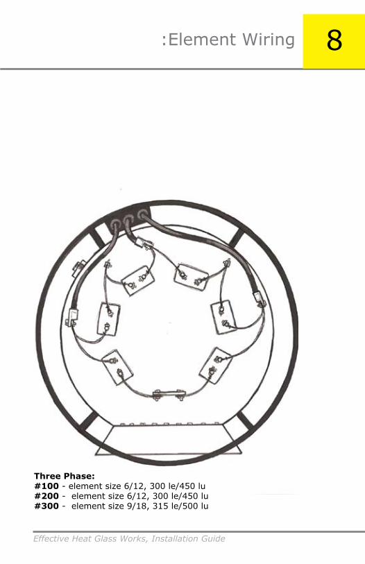
4. Arrange the straps according to the pattern that corresponds with your furnace type, provided in the following pages (numbers). Each furnace and phase has a specified number of straps, and designated connections.
5. Next, you join the strap ends. Get the 5/16” hardware, the 1/2” wrenches, and the bottle of No-Alox. Begin by applying the No-Alox to the strap ends.
Conect the strap ends from each link together by putting the hardware through the holes. If there are two straps per terminal connect all four straps together. Do not separate the two pairs of straps.
Each bolt assemble has to have two washers and at least one lock washer. There are several longer bolts. These are for the welding cable connections so be sure you are using the shorter ones to connect the strap ends.
*Be sure to arrange the straps with the ends pointing towards the outside of the furnace so the links do not touch each oher. Allowing the straps to tough will cause a short.
*Above:#200 & 300 Single Phase wiring pattern.

Effective Heat Glass Works, Installation Guide
8:Element Wiring
7. Once you have made all the connections, your furnace should look similar to what is shown to the right. Before moving on to the next step, re-tighten all of the bolts on the straps and all of the connection bolts. Loose connections are the #1 cause of failure in an electrical system.
Don’t put the top cage on yet. Wait until the very end, you will need to tighten the connections one more time.
6. Now, pull the welding cables through the strain relief plate on the back. The designations of the welding cables are shown on the wiring pattern diagrams as well. Use the larger bolts provided. Each cable is labeled. Place according to the diagrams.
*Do not lay the welding cables across any straps or elements.
new pic

Effective Heat Glass Works, Installation Guide
8 :Element Wiring
The diagrams that follow are labeled accordingly to the phase and furnace size. They give give accurate placements of the strap connections so follow the cable designations and strap patterns closely.
Single Phase:#75 - element size 6/12, 280 le/400 lu#100 - element size 6/12, 300 le/450 lu

Effective Heat Glass Works, Installation Guide
8:Element Wiring
Single Phase:#200 - element size 6/12, 300 le/450 lu#300 - element size 9/18, 300 le/500 lu

Effective Heat Glass Works, Installation Guide
8 :Element Wiring
Single Phase:#400 - element size 9/18, 315 le/500 lu#600 - element size 9/18, 500 le/500 lu
Effective Heat Glass Works, Installation Guide
8:Element Wiring
Three Phase:#100 - element size 6/12, 300 le/450 lu#200 - element size 6/12, 300 le/450 lu#300 - element size 9/18, 315 le/500 lu

Effective Heat Glass Works, Installation Guide
8 :Element Wiring
Three Phase:#400 - element size 9/18, 315 le/500 lu#600 - element size 9/18, 300 le/500 lu

Effective Heat Glass Works, Installation Guide
8:Element Wiring

Effective Heat Glass Works, Installation Guide
9 Thermocouple Wiring
Now that you have set up the cooling system and wired the elements, the next step is the Thermocouple wiring.
The thermocouple wires are type R, rated for temperatures up to 3000F. There are two thermocouple wires in the assembly; one is wired to your 981 controller and one is wired to your Over-Temperature Protection.
When the Furnace is heated up you will notice a difference in the temperature readings, these readings will come closer together. While thermocouples are a good indication of the temperature, you should always pay more attention to the glass rather than the temperature reading. That is why you should not rely on exact temperatures for batching, cooking or working.
Flange Fitting
Liquid-Tite
Liquid-Tite Fitting
Thermocouple Assembly
Thermocouple Wires
Effective Heat Glass Works, Installation Guide
9:Thermocouple Wiring
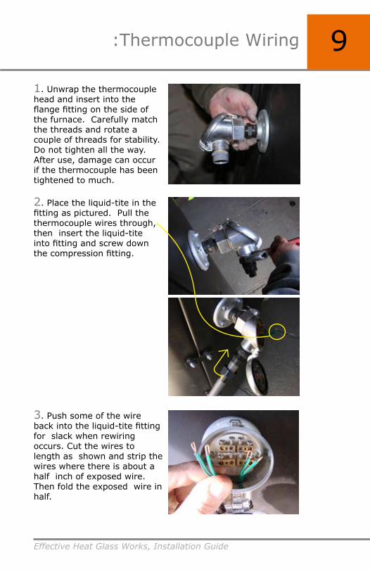
1. Unwrap the thermocouple head and insert into the flange fitting on the side of the furnace. Carefully match the threads and rotate a couple of threads for stability. Do not tighten all the way. After use, damage can occur if the thermocouple has been tightened to much.
2. Place the liquid-tite in the fitting as pictured. Pull the thermocouple wires through, then insert the liquid-tite into fitting and screw down the compression fitting.
3. Push some of the wire back into the liquid-tite fitting for slack when rewiring occurs. Cut the wires to length as shown and strip thewires where there is about a half inch of exposed wire. Then fold the exposed wire in half.

Effective Heat Glass Works, Installation Guide
9 :Thermocouple Wiring
4. The black wire is positive and the red wire is negative. There are positive and negative symbols engraved on the ceramic plateunderneath both thermocouples.
5. The Center Screws on each thermocouple should never be unscrewed. The outer screws are for the wires to go into the holes in the terminal block. Insert the exposed folded end in to the connector with positive and negative in the appropriate sides and screw down tightly.

Effective Heat Glass Works, Installation Guide
9:Thermocouple Wiring

Effective Heat Glass Works, Installation Guide
10 Control Unit Wiring
Wiring Components:
Illustrated below are the basic components that we will be working with in this section.
The control stand is pre-wired to be a maximum of 8 feet away from the furnace.
*Extreme caution needs to be taken when working with electricity. A licensed electritia should make all the connections

Effective Heat Glass Works, Installation Guide
:Control Unit Wiring 10
Control Panel
*Breaker Box
*MFD (main fuse disconnect)
Transformer
* The Breaker Box and the MFD are not included. The Braker Box should be your existing box and the MFD will have to be purchased
Control Unit

Effective Heat Glass Works, Installation Guide
10 Control Unit Wiring
The Control Panel is mostly prewired and tested in our facility, however, there are still a few connections you must make. You should have a liscenced electritian make all of the connections from your breaker to the control pannel.
The control unit system consists of two main components:
1. Control Panel
2. Transformer
*Extreme caution needs to be taken when working with electricity.
There are several indicators and controls on the the face of the Control Unit that will be important.
981
Overature limiter
Power indicator light
On/off switch
Door lights
a
d
b
c
e
a
d
bc
e
Control Panel & Transformer:

Effective Heat Glass Works, Installation Guide
:Control Unit Wiring 10Inside the Control Panel you will find:
Logo PLC (programable logic control)
Icecube Relays (interposing relays)
SCR
Safety
Contactors
High PowerLow PowerFuses

Effective Heat Glass Works, Installation Guide
10 :Control Unit Wiring
Wiring Connections:
By now you should have the Blower, the Door Switch and the Thermocouples all connected to the Control Panel. Now you are ready to hook power up to the Control unit
There are two separate circuits that need to be connected to hook up the furnace to a power source: the Control Circuit and the Power Wiring. Both the Power Wiring and the Control Circuit need to connect the control Panel to the Breaker Box. The Control Circuit will also pass through an MFD before it connects to the Breaker Box. Each connectionwill be outlined in greater detail on thefollowing pages.
The control stand is pre-wired to be a maximum of 8 feet away from the furnace.
*Extreme caution needs to be taken when working with electricity.
Door switch
Blower
Thermocouples

Effective Heat Glass Works, Installation Guide
:Control Unit Wiring 10
1. The power wiring to the safety
2. The control circuit to the icecube relays
3. The power wiring to the MFD
4. The power wiring and the control circuit to the breaker box

Effective Heat Glass Works, Installation Guide
:Control Unit Wiring
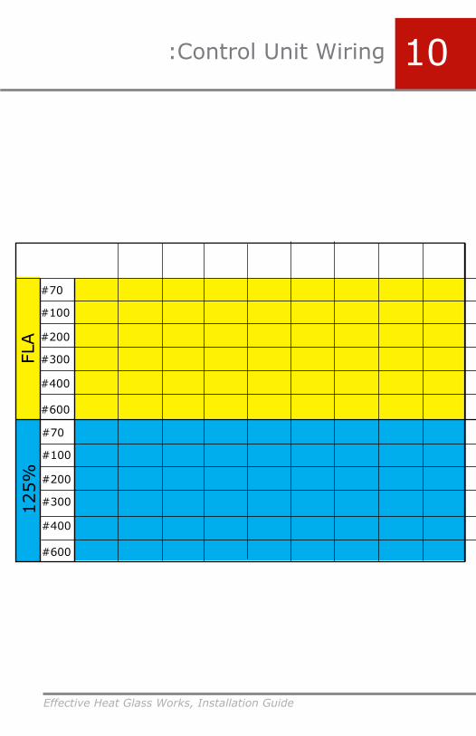
The power wring that feeds the elements should be rated at 125% of the FLA (Full Load Amperage). This means that if you have 100 amps of current, you should have a conductor (wire) that is rated to cary at least 125 amps.
The chart on he following page shows the FLA and the 125% rating for the power circuits of the various sizes of furnaces with the most common voltages. Stranded THHN wire is reccomended.
Connect the power wiring to the the safety contactor in the center of the control panel. The connections are labled x1, x2, and x3 on the backplane.
You should tighten these connections repeatedly to compensate for Cold Creep. Tighten them about 30 min after you first connect them and then again after you run the firnace. After this you should only have to tighten them every four months or so.
10
1. The power wiring to the safety
Effective Heat Glass Works, Installation Guide
:Control Unit Wiring
#70
#100
#200
#300
#400
#600
#70
#100
#200
#300
#400
#600
FLA
125%
10
Effective Heat Glass Works, Installation Guide
10 Control Unit Wiring
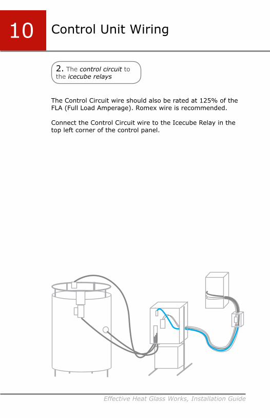
2. The control circuit to the icecube relays
The Control Circuit wire should also be rated at 125% of the FLA (Full Load Amperage). Romex wire is recommended.
Connect the Control Circuit wire to the Icecube Relay in the top left corner of the control panel.

Effective Heat Glass Works, Installation Guide
:Control Unit Wiring 10
3. The power wiring to the MFD
Every Furnace requires a main fuse disconnect line inside of the circuit breaker in the main breaker panel. The disconnect should be mounted within five feet of the control panel.
Both the Control Circuit and the Power Wiring will pass through the MFD. However, only the Power Wiring will connect. the Control Circuit will run along side the connection in the box but will not connect to anything.
5’

Effective Heat Glass Works, Installation Guide
10 :Control Unit Wiring
4. The power wiring and the control circuit to the breaker box
Now you are ready to connect both the Control Circuit wire and the Power Wiring to the Breaker Box.
The Furnace requires a dedicated breaker that meets the specifications provided by specs sheet.
* Wiring electrical circuits can be dangerous, always check and verify that the power is off.
There need to be two separate circuits, one for the high voltage that powers the elements and a 10 amp 120 volt breaker dedicated for the control circuitry.

Effective Heat Glass Works, Installation Guide
:Control Unit Wiring 10Clean up:
Now that you have made all the neccassary wiring connections, you need to organize and secure all the loose wires.
Run the wire for the door switch around the outside of the top ring. Use zip ties to secure the cable as shown.
Gather the extra slack from the door switch, blower and thermocouple wires, coil it and zip-tie them together. You can tie them to the Control Unit structure to keep them off the ground.

Effective Heat Glass Works, Installation Guide
Control Unit Wiring
Two #600 kit units
#100 unit
10

Effective Heat Glass Works, Installation Guide
:Control Unit Wiring
#300 unit
#300 unit
10

Effective Heat Glass Works, Installation Guide
11 Maintenance
Effective Heat Glass Works, Installation Guide
11:Maintenance

Effective Heat Glass Works, Installation Guide
11 Maintenance

Effective Heat Glass Works, Installation Guide
11:Maintenance

Effective Heat Glass Works, Installation Guide
12 Crucible Change
Crucible changes are recommended about every 80 batches and when a leak occurs.
1. To change a crucible pry away the pot from the sill and place a small section of soft brick between the crucible and sill of the face casting. This is done while the furnace is still hot. This ensure that the crucible doesn’t cool and harden to the castings. Once the soft brick is in place then open the door and turn off the furnace. When the temperature is tolerable begin freeing the crucible to strap and lift out of the furnace.
Pic
Crucible leaks have a slightly different protocol. When a crucible leaks the cleanout port has to be opened to scrape out the glass that has accumulated in the bottom of the base casting. Turn the furnace up to 2300˚ F and scrape out as much glass as possible. Then begin the normal procedures starting with step numbe one.
2. Turn the funace off by flipping rthe breaker switch. Once the furnace has come down in temperature start removing the thermocouple by unwiring and removing the liquid-tite from the fitting first, then use a 5/16” hex driver tounscrew the self drilling screws that hold the flange in place. Set somewhere safe.

Effective Heat Glass Works, Installation Guide
12:Crucible Change
2. Turn the funace off by flipping rthe breaker switch. Once the furnace has come down in temperature start removing the thermocouple by unwiring and removing the liquid-tite from the fitting first, then use a 5/16” hex driver tounscrew the self drilling screws that hold the flange in place. Set somewhere safe.
3. Next, undo all the connections between the elements leaving the straps connected to the element terminals. Disconnect and remove the welding cables aswell.
Remove the clear hoses from the coolers by making a slit down the hose the length of the connection and wiggle off. Leave the hoses connected tothe manifold.
4. Remove all the elements with extreme care as some deformity has occurred due to temperature. Place all the elements safely away from the work area.
5. A chain hoist is required toremove the crown and the crucible. An average 1 ton chain hoist is more than adequate. A beam that is high enough to compensate for thelength of the hoist and the crucible is critical.
If the hoist is not placed high enough the crucible will not clear the top ring. A forklift works well if the ceilings are high enough to lift the forks for proper working height.

Effective Heat Glass Works, Installation Guide
12 :Crucible Change
6. Fish a strap through twoof the holes that seem to be centered on the crown.
7. Next, tie the straps into a solid but removable knot. Tighten the knot so that there is little slack in the tow rope.
8. Move either the fork lift or the chain hoist into place. Lift slowly and begin to raise the crown off the top. Lift the crown free then move it away from the furnace set the crown on 2x4’s or some blocks. Something to keep it from pinching the tow cable.

Effective Heat Glass Works, Installation Guide
12:Crucible Change

Effective Heat Glass Works, Installation Guide
12 :Crucible Change

Effective Heat Glass Works, Installation Guide
12:Crucible Change