effective moment of inertia and deflections of reinforced … · 2018-10-22 · effective moment of...
TRANSCRIPT

Engineering Journal ofUniversity of Qatar, Vol. 8, 1995, p.lOl- 125
As As' b c
C'
Ct Cu d d' E Ec
EFFECTIVE MOMENT OF INERTIA AND DEFLECTIONS OF REINFORCED CONCRETE
BEAMS UNDER LONG-TERM LOADING
Khalid M. Mahmood"', Samir A. Ashour"""and Soliman I. AI-Noury"' * Professor ** Associate Professor
Civil Engineering Department, King Abdulaziz University Jeddah- 21413, Saudi Arabia.
ABSTRACT
The paper presents a method for estimating long-term deflections of reinforced concrete beams by considering creep and shrinkage effects separately. Based on equilibrium and compatibility conditions a method is developed for investigating the properties of a cracked transformed section under sustained load. The concept of effective moment of inertia is extended to predict initial-plus-creep deflections. Long-term deflections computed by the proposed method are compared with the experimental results available in the literature and with the values obtained by the ACI Code method. This comparison shows that for beams having span/thickness ratio greater than 25, the ACI Code method underestimates long-term deflections while the proposed method gives a better estimate with computed to measured deflections ratio equal to 1.0.
= =
NOMENCLATURE
Area of tension steel Area of compression steel Width of beam section Creep coefficient (multiplier) for concrete strain at an uncracked section at time t Creep coefficient (multiplier) for concrete strain at a cracked section at time t Creep coefficient for plain concrete at time t Ultimate creep coefficient for plain concrete Effective depth ofbeam section Compression steel depth factor Modulus of elasticity Modulus of elasticity of concrete under short-term loading
101

Ect Es fc' fr fcJct
fsJst
fs',fst'
fuJut
h I Ic,lct
IeJet
Ig IuJut
k,kt
L M Ma Mer m n
nt ntt
p p'
Sc,Sct
t
vo
K.M. Mahmood, S.A. Ashour and S.l. Al-Noury
Reduced or sustained modulus of elasticity of concrete at time t = Modulus of elasticity of steel
Compressive strength of concrete under short-term loading Modulus of rupture Extreme fibre compressive stresses in concrete at a cracked section, immediately after loading and at time t, respectively
= Stresses in tension steel at a cracked section, immediately after loading and at time t respectively Stresses in compression steel at a cracked section, immediately after loading and at time t, respectively Extreme fibre compressive stresses in concrete at an uncracked section, immediately after loading and at time t, respectively Total thickness ofbeam section Moment of inertia Moments of inertia of cracked transformed sections immediately after loading and at time t, respectively Effective moments of inertia for calculating beam deflections immediately after loading and at timet, respectively Moment of inertia of gross concrete section ignoring reinforcement Moments of inertia of uncracked transformed sections immediately after loading and at time t, respectively Neutral axis depth factors for cracked transformed section immediately after loading and at time t, respectively Span length Bending moment Maximum span moment Cracking moment of a section Beam constant (Sec Eq. 17) Modular ratio for short-term/immediate loading Increased modular ratio at time t Transformed area multiplier for tension steel at a cracked transformed section at time t Tension steel ratio= Aslbd Compression steel ratio= As'lbd Section moduli for cracked transformed sections with respect to extreme compression fibre, immediately after loading and at time t respectively Section moduli for uncracked transformed sections with respect to extreme compression fibre, immediately after loading and at timet respectively time under sustained loading Short-term/immediate (initial) deflection after loading
102

Vcp Vsh Vt
Y,Yt
Effective Moment of Inertia and Deflections ofRC Beams Under Long-Term Loading
Initial-plus-creep deflection at timet == Shrinkage deflection at time t
Total long-term deflection at timet (Second subscripts M, A and P with vo and Vt stand for measured deflection, deflection computed by the ACI Code method and deflection computed by the proposed method respectively) Ratios of neutral axis depth to total depth (thickness) ofuncracked transformed sections immediately after loading and at time t, respectively Extreme fibre compressive strains at cracked sections immediately after loading and at time t respectively Shrinkage strain for plain concrete at time t Ultimate shrinkage strain for concrete Extreme fibre compressive strains at uncracked sections immediately after loading and at time t respectively Long-term deflection multiplier (ACI Code method)
INTRODUCTION
The use of higher strength materials and the strength method of design, resulting in shallower members, has increased the importance of serviceability checks in the design of reinforced concrete structures. For flexural members immediate or short-term deflections as well as time-dependant or long-term deflections, under service loads, need to be checked.
Immediate deflections are influenced by the magnitude and distribution of loads, span and conditions of restraint, section properties, material properties and the amount and extent of flexural cracks [ 1]. Taking into account most of these factors the ACI Code 318-89 [2] recommends that immediate deflection of a reinforced concrete flexural member under service loads be computed by using the formulas of elastic deflection with flexural rigidity equal to Ecle, where Ec is the short -term modulus of elasticity of concrete and Ie is the effective moment of inertia for the member. A comparison of deflections calculated by the ACI Code method with experimental results shows that the method gives excellent prediction of immediate deflections [3,4].
Long-term deflections are mainly due to the effect of creep and shrinkage and are influenced by a number of factors including stresses in the concrete, amount of tension and compression reinforcement, size of member, curing conditions, temperature, relative humidity, age of concrete at time of loading, and duration of
103

K.M. Mahmood, S.A. Ashour and S.I. Al-Nowy
loading [1]. The ACI Code [2] suggest that additional long-term deflection resulting from the combined effect of creep and shrinkage under sustained load be obtained by multiplying the corresponding immediate deflection by a factor A. that depends only on the duration of loading and compression reinforcement ratio. The application of this method to a large set of experimental results indicates a variability of± 62 percent in the estimation of long-term deflections [ 4]. There may be, therefore, instances when the simple method suggested by the ACI Code may not be applicable and it may become essential to estimate long-term deflection by considering creep and shrinkage effects separately.
This paper proposes a method for calculating long-term deflections of reinforced concrete beams by considering creep and shrinkage effects separately. Deflections due to creep are generally much greater than deflections resulting from all other time-dependent effects combined and are of primary interest [ 1]. The aim of this paper is to develop a method for predicting flexural rigidity and deflection due to creep under sustained loading. Giving due consideration to the effect of creep, compatibility and equilibrium, the paper develops expressions for some basic properties of a cracked transformed section which will facilitate the calculation of its moments of inertia at any time t. The concept of effective moment of inertia is extended to estimate member flexural rigidity and initial-plus-creep deflection under sustained load. Separate calculations for shrinkage defection are proposed to be carried out by Branson's method [5]. To establish the suitability of the method, deflection predictions using the proposed method are compared with experimentally measured long-term deflections as well as with the values obtained by the ACI Code [2] procedure.
LONG-TERM DEFLECTIONS
Total long-term deflection vt at any time t under sustained load can be expressed as a sum of initial-plus-creep deflection Vcp and shrinkage deflection Vsh, t.e.,
Vt = Vcp + Vsh (1)
Considering service loads, Vcp can be computed by using the formulas of elastic deflection employed for calculating immediate deflection with Ecle, the flexural rigidity of the member immediately after loading, replaced by Ectlet, the flexural rigidity at time t under sustained loading. Here Ect is the reduced modulus of elasticity of concrete and let is the effective moment of inertia of the member at time t. A method for calculating let is developed later in the paper.
104

Effective Moment of Inertia and Deflections ofRC Beams Under Long-Term Loading
Deflections due to shrinkage are independent of the applied loading but are in the same direction as those caused by gravity loading. A number of methods have been suggested for estimating shrinkage deflections. In the method proposed in this paper, Branson's method [5] is used for estimating shrinkage deflections.
EFFECTIVE MOMENT OF INERTIA
For calculating immediate deflections under service loads the ACI Code [2] recommends formulas for Ec and Ie. The formula for the effective moment of inertia Ie is:
(2)
where Mer is the cracking moment, Ma is the maximum span moment, Ig is the moment of inertia of the gross concrete section ignoring reinforcement, and Ic is the moment of inertia ofthe cracked transformed section.
In order to include the effect of reinforcement on the properties of uncracked section, lg in Eq. (2) can be replaced by lu, the moment of inertia ofthe uncracked transformed section to yield the following equation for Ie:
(3)
The use oflu in place oflg has already been recommended by Branson [5]. lu may be more accurately used for estimating Ie for heavily reinforced members and lightweight concrete members. Obviously, the cracking moment Mer for use in Eq. (3) should also be determined by using the uncracked transformed section. If the modulus of rupture, fr is evaluated correctly, the accuracy in determining the first cracking point will be improved using lu [5]-
Using Eq. (3), the flexural rigidity Ecle for a member immediately on loading can be expressed as follows:
(4)
105

----------------
K.M. Mahmood, S.A. Ashour and S.l. Al-Noury
As already indicated, the flexural rigidity for predicting initial-plus-creep deflection can be expressed as Ect let· The reduced or sustained modulus of elasticity for concrete Ect can be taken equal to Ecf(1 +Ct.), where Ct is the creep coefficient and is a function of relative humidity, concrete quality, duration of applied loading, and age of concrete when loaded [ 1]. The following relationship is suggested [5] between Ct, ultimate creep coefficient Cu and duration ofloading t (days) for concrete having "standard conditions", i.e., 4 in (100 mm) slump or less, 40 percent relative humidity, moist cured and loaded at an age of 7 days:
Ct = 10+ t0.60 Cu (5)
Correction factors for Ct have also been suggested [5] when the conditions are different from the above-mentioned standard conditions.
For initially cracked simply supported beams (being considered in this study), the values of Ma and McriMa will remain constant under sustained load. Effective moment of inertia let, and flexural rigidity Ect let at time t can then be expressed by the following equations which are similar to Eqs. (3) and (4) respectively:
ra (~:)' ru,{- (~)' },, (6)
Ectla ~ [(~:r +- (~:n I,,IIut] IutEot (7)
Here lut and let are the moments of inertia ofuncracked and cracked transformed sections respectively at time t.
While discussing the development of Eq. (2) it has been stated [5] that the equation is not sensitive to the power ofMcriMa with values of2.8 or 3.2. Noting this discussion and the limited data presently available on time-dependent deflections the power of3 has been retained in Eqs. (6) and (7).
In continuous members some redistribution of moments may occur under sustained load. Ignoring this redistribution the values of let for the critical positive and negative moment sections of a continuous member can be calculated with the respective values ofMa and Mcr!Ma used in computing Ie for those sections.
106

Effective Moment offuertia and Deflections ofRC Beams Under Long-Term Loading
TRANSFORMED SECTIONS
The properties of uncracked and cracked transformed sections immediately on loading are obtained by applying the concept of the modular ratio, n = EsiEc, where Es is the modulus of elasticity of steel [ 6]. The modular ratio concept assumes equal strains in the reinforcing steel and the surrounding concrete, i.e., perfect bond.
For reinforced concrete beams under sustained load an "increased" modular ratio nt = EsiEct can be defined. Noting the basic assumption of modular ratio concept, nt may be used for calculating the transformed areas of tension and compression reinforcement, and hence lut, for an uncracked section. Similarly, nt may be used for calculating the transformed area of compression reinforcement at a cracked section. However, this simple increased modular ratio approach does not seem to be valid for computing the transformed area of tension reinforcement at a cracked section under sustained load. The creep of concrete will increase bond deterioration and slip between steel and concrete which occur adjacent to cracks. The quasi-elastic method based on increased modular ratio will thus overestimate the tension steel area transformed to equivalent concrete area. The transformed area of tension reinforcement and other properties of a cracked transformed section under sustained load need to be obtained by considering strain compatibility and equilibrium conditions. Simultaneously, it is important to consider any relationship that may exist between the properties of uncracked and cracked transformed sections immediately after loading and under sustained load. The following equations for the properties of the two types of sections have been developed by assuming that the stresses are within linear elastic range. This assumption generally implies that the steel stress is below yield point and the concrete stress is not greater than 0.5 fc', where fc' is the cylinder compressive strength [6].
Uncracked Section
For an uncracked section subjected to a bending moment M, Fig. 1 shows transformed ~ections, strain distributions and stress distributions immediately after loading (t = 0) and at time t under sustained load. Since the stresses and strains arc within the elastic range, the extreme fibre strains, Eu immediately after loading and Eut = (1 +C) Eu, at timet, can be expressed as follows:
fu MY h (8) =
Ec Eclu
and
107

&ut = f ut
Ect
K.M. Mahmood, S.A. Ashour and S.l Al-Noury
or (1 +C) &u (9)
where h is the total depth (thickness) of the section, fu and fut are the extreme fibre compression stresses in concrete, y and Yt are the ratios of neutral axis depth to the total depth (thickness), and lu and lut are the moments of inertia ofuncracked transformed sections immediately after loading and at timet, respectively. Cis the creep coefficient (multiplier) for concrete strain at the uncracked section under consideration. Because of the influence of section properties, the value of C may be less than Ct, the creep coefficient obtained from tests on plain concrete.
h d
ACTUAL SECTION
, A a
.As • • • '-- . .__ ____ _,
TRANSFORMED SECTION
STR.AIN DISTRIBUTION
(a) IMMEDIATELY AFTER LOADING (t:O)
STRESS OISTRIBUT ION
fut = (l+(.)C.u
(b) UNDER SUSTAINED LOAD AT TIME t
Fig. 1: Uncracked section
108

Effective Moment oflnertia and Deflections ofRC Beams Under Long-Term Loading
From Eqs. (8) and (9) the following relationship between C, Ct and the properties of uncracked transformed sections is obtained:
1+C Eclu Yt = Ectlut Y
(10)
Substituting Ec Ect = (1 + Ct)
in Eq. (10),
1+C (1 + Ct) lu Yt (1+Ct)~ = -- = lut Y Sut
(11)
where Su = lu/y.h and Sut = lutfYt·h are the section moduli for the uncracked transformed sections, with respect to the extreme compression fibre, immediately after loading and at time t under sustained load.
Cracked Section
Figure 2 shows transformed sections, strain distributions and stress distributions for a cracked section immediately after loading and at time t under sustained load with bending moment M. For the transformed section immediately after loading, the modular ratio n has been used to define the transformed areas of tension and compression steels. For the transformed section at t, nt has been used to define the transformed area of compression steel only. In keeping with the previous discussion, the transformed area for tension steel at time t has been taken equal to ntt As, where ntt is defined as the transformed area multiplier for tension steel at time t. C' is the creep coefficient for concrete strain at the cracked section under consideration. At this stage it may be assumed that C' is not equal to C. It is to be noted that with the cracked transformed section modeled by using ntt, the value at the level of tension steel in the strain distribution (Fig. 2b) does not represent the steel strain at time t. However, the strain in tension steel can be obtained from the corresponding stress once its value has been determined.
Following the procedure used for uncracked section, a relationship between C', Ct and the properties of cracked transformed section can be obtained:
1+ C' = Eclc kt
Ectlct k (12)
109

K.M. Malunood, S.A. Ashour and S.I. Al-Noury
or
l+C' (13)
where k and kt are the neutral axis depth factors and Ic and let are the moments of inertia of the cracked transformed sections immediately after loading and at time t under sustained load, respectively. Sc taken as Icfkd and Set taken as Ictlkt.d are the section moduli for cracked transformed sections immediately after loading and at time t. d is the effective depth of the section.
(a) IMMEDIATELY AFTER LOADING (t:O)
' I I
; : n tt A5 ,
L----- ---- .J
1st
(b) UNDER SUSTAINED LOAD AT TIME t
Fig. 2: Cracked section
110

or
Effective Moment offuertia and Deflections ofRC Beams Under Long-Term Loading
From Eqs.(ll) and (13) the following expressions are obtained:
Set = Sc (1 +C) Sut Su (1 + C')
Iu let Yt k (1+C') ---- = 1.0 lut Ic Y kt (1 + C)
(14)
(15)
Eqs. (14) and (15) represent relationships between the uncracked and cracked sections. These equations can be used to check the validity of any procedure used for calculating the properties of the two types of sections.
For the cracked transformed section at timet, the value ofkt can be determined by considering equilibrium conditions immediately after loading and under sustained load.
Taking moments about the tension steel, for the stresses immediately after loading (Fig. 2a):
(16)
or
= 3k - k2 k-d'
6 + p' (n -1) k (1- d') = m (constant) (17)
M
Similarly, from the stress distribution at timet (Fig. 2b):
(18)
and
M = [3kt-kt +p'(n- 1)kt-d'(l-d')][l+C') (1 9) fc bd2 6 kt 1 + Ct
Here fc and fct are the stresses at the extreme fibre in compression, immediately after loading and at time t, p' is the compression steel ratio, b is the width, and d' is
111

K.M. Mahmood, S.A. Ashour and S.I. Al-Noury
a factor which defines the depth of the compression steel As' with respect to the effective depth d.
Equating the right hand sides ofEqs. (17) and (19), and rearranging:
1+C'
1+Ct (20)
Trial and error solution of Eq. (20) will provide the value ofkt. In the case of a singly reinforced rectangular section, Eq. (20) reduces to a quadratic equation, whose solution yields the following expression for kt:
( 1 + CtJ ( 2) kt = 1.5 ±) 2.25- 1 + C' 3k - k (21)
Once the value of kt has been determined, ntt is obtained by taking moments of areas of the transformed section at timet (Fig. 2), about the neutral axis. The final expression for ntt is:
ntt = kr + 2 Cncl) p' Ckcd') 2p (1-kt)
(22)
In the case of a singly reinforced rectangular section, Eq. (22) reduces to the following form:
lltt 2p (1- kt)
(23)
Having calculated the values of kt and ntt, the moment of inertia let for the cracked transformed section at time t (Fig. 2b) can be worked out.
If all the properties for uncracked and cracked sections are correctly calculated, Eqs. (14) and (15) will be satisfied.
Stresses in Concrete and Steel
Stresses in concrete at different fibres of uncracked or cracked section can be calculated directly by using the properties of corresponding transformed section and
112

Effective Moment offuertia and Deflections ofRC Beams Under Long-Term Loading
the bending equation of elastic homogeneous beams. Stress in reinforcing steel will be a product of the appropriate value of modular ratio/transformed area multiplier and the stress in the transformed section at the level of the reinforcement. The value of n will, therefore, be used for calculating stresses in tension and compression steels at uncracked and cracked sections immediately after loading. Under sustained load, nt will be used for calculating stresses in tension and compression steels at uncracked sections as well as in compression steel at a cracked section, while ntt will be used for calculating stress in tension steel at a cracked section.
COMPUTATION PROCEDURE AND SIMPLIFIED EQUATIONS
For a gtven section and material parameters, the properties of uncracked transformed sections (y, lu, Yt and lut) immediately after loading and under sustained loading (Fig. 1) and those of a cracked transformed section (k and lc) immediately after loading (Fig. 2) can be readily computed. The value of C can then be calculated from Eq. ( 11). For the determination of C' the following procedure can be adopted:
a) Assume a value ofkt
b) Calculate ntt from Eq. (22)
c) Calculate let for the cracked transformed section using nt for compression steel and ntt for tension steel (Fig. 2)
d) Calculate (1 + C') from Eq. (13)
e) Substitute all the relevant values in Eqs. (20) and (15) to see whether these equations are satisfied
f) Repeat the above steps to obtain a value ofkt and the corresponding values of ntt, let and C' which satisfy Eqs. (20) and (15).
The above procedure was used to develop a computer program to analyze a large number of rectangular beam sections with different combinations of practically possible section and material parameters. The results of this parametric study indicate that Eqs. (20) and (15) are satisfied only when C' = C, i.e., the creep coefficients (multipliers) for concrete strains in uncracked and cracked transformed sections at any time under sustained loading, are equal. This is a logical finding because the same value of the creep coefficient, Ct for plain concrete has been used
113

K.M. Mahmood, S.A. Ashour and S.I. Al-Noury
in the derivation of equations for the two types of transformed sections and that Eqs. (11) and (13), for C and C', respectively, are independent of the bending moment and the stresses being induced.
and
By substituting C' = C, Eqs. (14) and (15) take the following simplified form:
Set = Sc Sut Su
_h_lctYt~ = l.O lut lc Y kt
(24)
(25)
Eq. (24) shows that if all the values are correctly substituted, the ratio of section moduli with respect to extreme compression fibre for the two types of sections under sustained load, with stresses within elastic range, will remain constant and will be equal to the ratio for the sections immediately after loading.
The substitution of C' = C simplifies the above-mentioned iterative procedure for determining the properties (kt, ntt and let) ofthe cracked transformed section under sustained load. In the case of singly reinforced beams, kt can be computed directly from Eq. (21).
The results of this study also indicate that Eqs. (15) and (25) are not satisfied when the properties {kt, let and C') of the cracked transformed section, based on a simple increased modular ratio approach (ntt = nt), are substituted in these equations with all other terms remaining unchanged.
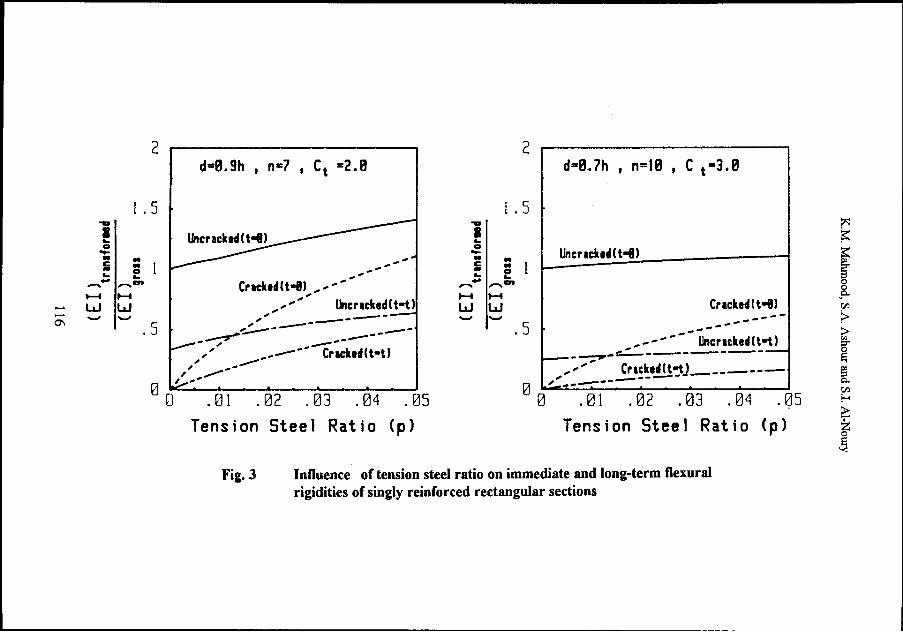
Figures. 3-6 present typical results to show the influence of different parameters on flexural rigidities of uncracked and cracked transformed sections computed by the proposed method. For two different sets of section and material parameters, Fig. 3 shows the influence of tension steel ratio on the flexural rigidities of singly reinforced uncracked and cracked transformed sections, immediately after loading and under sustained load. Keeping all other section and material parameters constant, Fig. 4 shows the influence of effective depth d on ntt and flexural rigidities. Fig. 5 shows the beneficial effect of compression reinforcement on increasing flexural rigidities and therefore reducing deflections under sustained loads. The effect of compressive strength of concrete on flexural rigidities is shown in Fig. 6. Compressive strength of concrete influences the modulus of elasticity Ec, modular ratio n and the ultimate creep coefficient Cu. The graphs in Fig. 6 have
114

Effective Moment offuertia and Deflections ofRC Beams Under Long-Term Loading
been drawn for different values of fc' by using the appropriate values of Ec and Cu based on the study at Cornell University [6]. The results in Figs. 3-6 show that besides compression steel ratio p', effective depth d, tension steel ratio p and compressive strength of concrete fc' may have appreciable effect on flexural rigidities. These factors should, therefore, be considered in predicting deflections of reinforced concrete beams under sustained loads.
The results of parametric study show that in some cases a difference as high as 15 percent in the values ofEct Ictflc Ic and Ect lutiEc lu may occur. One typical set of results showing the difference in flexural rigidities of uncracked and cracked sections is presented in Fig. 4. In Figs. 5 and 6 only the graphs for Ect lctiEc Ic have been shown as the values for Ect lutiEc lu were very close to these values. The study, therefore, indicates that for most sections:
Ectlct = Ectlut Eclc Eclu
or
let = lc (26) lut lu
Replacing lctllut by Icllu and Ect by Ec(l + Ct) in Eq.(7), therefore, yields:
(27)
In other words, the initial-plus-creep deflection Vcp at any time t under sustained loading can be predicted for most cases by multiplying the corresponding immediate deflection with ( 1 +Ct) lullut·
115
.......
....... 0'1
2
l.5 i ....
0
c .. - 0 -;1 .. .... ....
~.,. "'"'en
........ , ...... w w -- .5
d=8.9h J n=7 J ct =2.8
Cracked(t-8) , ..................... ... , ... ......
............... ' Uncracked(t-t)
2 d•8.7h , n=IB , C t•3.8
l . 5 ..... I L. 0 -. .. c .. - 0 L. ....
,...... ~ "'"'en H H w w - ·-
Uncrackt~(t-8)
Cracked(t-tJ)
. 5 ~ -------------~::.---------
,' ," ------------0 ,,,:.-------- Crodtodlt•tl
0 .01 .02 .03 .04 .05 Tension Steel Ratio (p)
------ Uncracked(t-t) ~-___,..::....-.--------
............ Cracked(t-tj ______ _
~~ --------------0 L c-- , ' . , 0 . 01 . 02 . 03 . 04 . ~5
Fig. 3
Tension Steel Ratio (p)
Influence of tension steel ratio on immediate and long-term flexural rigidities of singly reinforced rectangular sections
~
~
I Cf.l
~ :t>
f [ Cf.l f-;
2::; z ]

Effective Moment of Inertia and Deflections ofRC Beams Under Long-Term Loading
.. .. .., ... :l :l
lfJ "' > > e ., ....... ., lfJ I-
I "0 en ., c e o e
...J ......
4
3
2
....
0 I
n = 9 1 Cu =,3.0 (d=0.7h I dd=0.1h I p=0.03 I p=0.015l (d=0.9h I dd=0.1h I p=0.0234 I p=0.0117l
::::: -- =
10
v
---~-"u'" _/ __ -
---- = = --
100 Time (tl days
_-j--
1000 10000
Fig. 4: Influence of effective depth on flexural rigidities and ntt
.. .. ., .., :l :l
lfJ ... >> e .., ....... ., lfJ I-
I "0 D'J ., c e o e
...J ......
3
2
0 I
n .. B I cl4 .. 2.0
(d .. 0.9h I dd .. 0.th I p•0.030l
-------- ri"fl -·-P~B.Sp ____ p'a8
i=:::.;- -·-
10 100 Time (tl days
---H
E 1 I[ 1 c\ c\ c c .:.=.=::-----:=-
II Ill
1000 10000
Fig. 5: Influence of compression steel ratio on flexural rigidities and ntt
117

K.M. Mahmood, S.A. Ashour and S.I. Al-Noury
(d=0,9h 1 p=0,015)
"''"' Q)IQ) :J :J
-;I-; >> el Q) L. +-' Q) ta t-j·-1 -c
g'l' ~ o e ....J ......
Time (t) days
Fig. 6: Influence of compressive strength of concrete on flexural
rigidities and Ott for singly reinforced rectangular sections
COMPARISON OF MEASURED AND COMPUTED LONG-TERM DEFECTIONS
Using the data reported in different laboratory studies [7-11], immediate and long-term deflections of a number of simply supported beams were computed by the proposed method and were compared with the measured values and the values estimated by the ACI Code method. Table 1 shows the necessary data, measured and computed deflections and the results of statistical analysis for all the beams. In Table 1, VOM and VtM are the measured immediate and long-term deflections respectively, voA and vtA are the immediate and long-term deflections computed by using the ACI Code method, while vop and VtP are the immediate and long-term deflections computed hy the proposed method. VtP is the sum of the initial-pluscreep deflection Vcp ana the shrinkage deflection Vsh (Eq. 1).
For rectangular beams in Table 1, initial-plus-creep deflections Vcp were computed using Ect let with let determined by the already stated iterative procedure. For the T -beams ofYu and Winter the values of vcp were calculated by adopting
118

..... ..... \0
Table 1: Comparison of Measured and Computed Deflections for Simply Supported Beams
Measured Computed Deflections++ Deflections
ACI Code Method Proposed Method Beam NO.+ L/h p'
VQt1 vtii VOA vOA vtA vtA vOP vOP v vsh vtP co (mm) (mml (mm) VOM (mml vtr-1 (mm) vOM (mln) (mml (mm)
1 2 3 4 5 6 7 8 9 10 11 12 13 14
Rectangular Beams -- Washa and Fluck7 : t=30 months, Cu=2.5, e:sh,u =0.00075
A1,A4 20 0.0163 13.46 23.62 15.34 1.14 29.88 1. 26 13.80 1. 02 28.12 0 28.12 A2,AS 20 0. 0077 15.75 32.26 15.77 1. 00 35.38 1.10 14.52 0.92 32.84 5.35 38.19 A3,A6 20 0 17.02 44.70 16.26 0.96 44.23 0.99 15.30 0.90 39.68 9.07 48.75 81,84 30 0.0167 23.37 51.05 25.64 1.10 49.69 0.97 23.22 0.99 51.47 0 51.47 82,85 30 0.0083 24.89 65.02 25.88 1. 04 57.29 0.88 23.87 0.96 58.03 7.69 65.72 83,86 30 0 26.42 86.36 26.18 0.99 71.21 0.83 24.63 0.93 69.31 13.71 83.02 C1,C4 so 0.0167 40.13 80.01 43.63 1. 09 84.57 1. 06 39.76 0.99 84.37 0 84.37 C2,CS so 0.0083 43.43 100.58 44.38 1. 02 98.26 0.98 41.19 0.95 95.83 13.35 109.18 C3,C6 so 0 47.75 140.72 45.35 0.95 123.35 0.88 42.92 0.90 116.93 23.79 140.72 D1,D4 30 0.0167 11.94 27.69 15.83 1. 33 30.68 1.11 14.46 1.21 30.64 0 30.64 D2,DS 30 0.0083 14.22 33.02 16.11 1.13 35.66 1. 08 14.97 1. OS 34.80 4.81 39.61 D3,D6 30 0 17.78 48.51 16.46 0.93 44.77 0.92 15.60 0.88 42.49 8.56 51. OS E1,E4 70 0.0159 59.44 123.95 52.72 0.89 103.28 0.83 47.57 0.80 106.53 0 105.92 E2,ES 70 0.008 55.88 128.78 53.11 0.95 118. so 0.92 48.82 0.87 120.36 15.45 135.81 E3,E6 70 0 62.99 184.91 53.59 0.85 145.76 0.79 50.26 0.80 142.34 27.52 169.87
Tee Beams-- Yu and Winter8 : t=6 months, Cu=2.0, e:sh,u =0. 000625
A 20 0 34.04 67.31 29.97 0.88 66.29 0.98 28.96 0.85 61.72 4.57 66.29 B 20 0.0051 31.49 56.64 29.46 0.94 52.83 0.90 28.45 0.90 58.42 2.54 60.96 c 20 0.01 30.23 56.89 29.72 0.98 49.53 0.87 28.70 0.95 56.90 0 56.90 D 20 0 32.26 67.06 32.77 1. 02 72.14 1. 08 32.26 1.00 65.02 4.57 69.60 E 14 0 12.95 29.21 14.22 1.10 31.24 1. 07 13.72 1.06 28.46 2.29 31.75 F 30 0 55.88 100.30 53.59 0.96 118.90 1.17 52.58 0.94 113.28 7.87 121.20
-- ---- ---- ---·- L_ -- -- -- --
Table 1 continued on the next page ...... .
vtP
vtM
15
1.19 1.18 1. 09 1. 00 1. 01 0.96 1. OS 1. 09 l. 00 1.11 1. 20 1. OS 0.86 1. OS 0.92
0.94 1.03 1. 00 1.04 1. 09 l. 21
-
tTi ~ a.. ell
f a 0 ....,
I 8.
I ~ e. ~
r ~ ~
i i.
O<l

.... t-.) 0
Table 1 continued
1 f2l_3_]C-4=r-·sJI-~ 7 1 8 I7lllDTD-T72u_I_13 1- 14 ]15
Rectangular Beams -- Corley and Sozen9 :
C1 12 0 3.05 7.37 2.95 0.92 C3 17 0 7.87 17.27 7.62 0.97 C4 17 0 6.10 15.49 5.84 0.96 -- - --
Rectangular Beams -- Bakoss et allO :
1B1 1B2
Rectangular Beams** -- Clarke et a~l :
B1 1410.012 4.78 8 .1~11 4.91 1.031
B2 14 0.012 4.30 7.93 4.72 1.10
s For all beams: T A AN Mean 1.012 TA I L Standard deviation 0.101 s y T S For beams with L/h 25: I I c s Mean 1.022 A L Standard deviation 0.122
t=23 months, Cu=3.0, e: sh,u=0.0003
7.37 1. 00 2.79 0.92 7.11 0.51 7.62 1. 03 20.32 1.18 7.37 0.94 20.83 1. 02 21.84 1. 26 15.75 1. 02 5.84 0.96 15.75 1. 02 16.76 1. 08
- --
t=500 days, Ct=2.4*, e:sh =0.00065*
0.99 1.16
t=6 months, <=t=2.26*
8.5911.0511 4.50,0.941 9.64 0 9.64 1.18 8.26 1.04 4.31 1.00 9.26 0 9.26 1.17
0.974 0.946 1. 069
0.173 0.083 0.098
0.915 0.942 1.044
0.20 0.104 0.098
+ For beam description, loading and other properties see the original reference. ++ In computing deflections by the ACI Code method and the proposed method, Ec and ~ were
calculated by the ACI Code formulas and the values of f~at the time of loading.
* Measured values at time t. **Data on shrinkage deformations not given in the reference. Therefore, beams having p'=p
(zero shrinkage deflection) have been included from that reference in this table.
~
~
f en :>
f [ en !-< 2::: z ]

Effective Moment oflnertia and Deflections ofRC Beams Under Long-Term Loading
the simple approach of multiplying the computed immediate deflections by the corresponding factor (1 + Ct)lullut·
Table 1 indicates that the use of Iu in place of Ig in the proposed method results in a slight decrease in the estimation of immediate deflections when compared with the ACI Code method. The mean and standard deviation of the ratio of computed to measured immediate deflections vop/voM by the proposed method are 0.946 and 0.083 respectively compared with 1.012 and 0.101 for voAivoM by the ACI Code method. Nevertheless, the mean and standard deviation of the ratio of computed to measured long-term deflections VtPIVtM by the proposed method are 1.069 and 0.098 respectively compared with the corresponding values of 0.974 and 0.173 for vtAIVtM by the ACI Code method.
The results in Table 1 show that the ACI Code method generally underestimates long-term deflections of beams having span to thickness ratio, Llh, greater than 25. The mean and standard deviation of computed to measured longterm deflections for beams with L/h > 25 (Table 1) are 0.915 and 0.20 respectively by the ACI Code method compared with 1.044 and 0.098 by the proposed method. For these beams the proposed method therefore gives a better estimate by considering creep and shrinkage components of deflections separately as well as by employing a detailed procedure for the computation of flexural rigidity under sustained load. The same is further true for beam 1B1 ofBakoss et al [10], in which loading produces Ma <Mer· For this beam vtAIVtM is 0.33 and vtplvtM is 0.99.
Since the main objective of this study was to develop a method for estimating effective moment of inertia and flexural rigidity of beams under sustained loads, a comparison of measured and computed initial-plus-creep deflections was made, as shown in Table 2. This Table includes those beams from Table 1 for which compression and tension steel ratios are equal (p' = p) and therefore theoretical values of shrinkage deflection Vsh are zero. Table 2 also includes the beams from Table 1 for which it was possible to deduct the shrinkage deflection component from the measured long-term deflection VtM at time t by using the data of companion specimens made and tested to study the shrinkage behaviour. The mean value and standard deviation of the ratios of computed to measured deflections for the sample of 16 beams in Table 2 are 1.09 and 0.11, respectively. This comparison in Table 2 shows that the proposed method, based on the calculation of flexural rigidity under sustained loads, gives a good estimate of initial-plus-creep deflection.
121

K.M. Mahmood, S.A. Ashour and S.I. Al-Noury
Table 2: Comparison of Measured and Computed Initial-Plus-Creep Deflections
Beam Measured Computed Ratio* No.+ (mm) _imm)
Al. A4 23.62 28.12 1.19
Bl. B4 51.05 51.48 1.01
Cl. C4 80.00 84.37 1.05
C2. C5 87.88 95.83 1.09
C3. C6 110.22 116.93 1.06
Dl.D4 27.69 30.64 1.11
D2.D5 27.92 34.80 1.25
D3.D6 39.62 42.49 1.07
El. E4 123.95 106.53 0.86
E2.E5 117.37 120.36 1.03
E3.E6 154.42 142.34 0.92
c 56.89 56.90 1.00
C1 6.00 7.11 1.18
1B1 18.12 22.55 1.24
B1 8.15 9.64 1.18
B2 7.93 9.26 1.17
Mean 1.09 Standard Deviation 0.11
+
* Beam Nos. are same as given in Table 1 from different references.
Ratio of computed to measured initial-plus-creep deflections.
Table 3 shows the computed values, immediately after loading and at t = 30 months under sustained load, of the neutral axis depth factor, concrete stress at the extreme compression fibre and stresses in compression as well as tension steels for the maximum moment (mid-span) cracked sections of the beams tested by Washa and Fluck [7]. These values were computed using the elastic bending equation and the properties of cracked transformed sections determined by the proposed method. The results in Table 3 show that due to the effect of creep, the neural axis depth increases, concrete stress decreases and stresses in compression and tension steels
122

..... N ~
Beam No.
A1, A4
A2,A5
A3, A6 B1, B4
B2, B5
B3,B6
C1, C4
C2, C5
C3,C6
D1, D4
D2,D5
D3,D6
E1, E4
E2,E5
E3,E6
Table 3: Computed Neutral Axis Depth Factors and Stresses in Concrete and Steel at the Maximum Moment Cracked Section of Beams Tested by Washa and Fluck
k kt fc fct fs fst fs (MPa) (MPa) (MPa) (MPa) (MPa)
0.364 0.361 9.17 5.86 37.92 76.05 135.69
0.384 0.396 9.96 7.45 43.51 104.94 135.42
0.405 0.450 10.89 10.00 - - 135.35
0.397 0.411 9.72 7.03 23.72 59.16 136.87
0.408 0.427 10.14 8.21 26.61 75.02 135.69
0.422 0.447 10.62 10.14 - - 134.25
0.390 0.396 9.24 6.34 31.17 68.67 136.04
0.405 0.422 9.80 7.59 35.30 90.67 135.07
0.424 0.458 10.52 9.86 - - 133.97
0.390 0.396 9.31 6.34 31.44 69.23 136.80
0.405 0.422 9.86 7.57 35.58 91.43 135.83
0.424 0.458 10.55 9.93 - - 134.73
0.393 0.410 9.72 7.17 21.79 56.95 140.04
0.403 0.422 10.07 8.27 24.34 70.74 138.88
0.416 0.438 10.50 10.07 - - 137.49 - -
fst (MPa)
138.52
137.83
137.69
143.97
140.80
153.56
141.55
139.42
135.76
142.31
140.18
136.52
147.48
144.11
138.66
ti:I ~ ~ ~·
( g,
[ ~
~ ~ §. ~ 0 ...., p; tti
~ f i i.
(JQ

K.M. Mahmood, S.A. Ashour and S.I. Al-Noury
increase with time. All these changes are in line with the usual description of reinforced concrete beam behaviour under creep effect [1,6].
CONCLUSIONS
1. The method proposed in this paper considers separately the effects of creep and shrinkage in estimating long-term deflections of reinforced concrete beams. For estimating initial-plus-creep deflection the concept of effective moment of inertia has been extended by considering the properties of uncracked and cracked transformed sections under sustained loads. For calculating shrinkage deflections Branson's method has been used. A comparison of the computed deflections with the test results from different sources confirms the suitability of the proposed method.
2. The quasi-elastic approach using increased modular ratio may not give correct properties of cracked transformed section for members subjected to sustained load. A better estimate of the properties of cracked transformed section can be obtained by giving due consideration to compatibility and equilibrium conditions. The properties of cracked section thus determined can be used for predicting not only initial-plus-creep deflections but also stresses (and strains) in concrete and steel reinforcement.
3. A comparison of computed and measured long-term deflections in the paper indicates that the ACI Code method underestimates these deflections for members with L/h greater than 25. The proposed method gives a better estimate oflong-term deflections for beams with L/h greater than 25.
4. The results of parametric study show that for any type/grade of concrete the material properties (Ec, Ct) have appreciable affect on flexural rigidities of reinforced concrete members under sustained loads. An improvement in the determination of these properties will, therefore, lead to a better estimation of long-term deformations.
REFERENCES
1. ACI Committee 435, 1966. "Deflections of Reinforced Concrete Flexural Members", (ACI 435.2R-66)(Reapproved 1984), American Concrete Institute, Detroit, p. 22.
124

Effective Moment of Inertia and Deflections ofRC Beams Under Long-Term Loading
2. ACI Committee 318, 1989. "Building Code Requirements for Reinforced Concrete (ACI 318-89)", American Concrete Institute, Detroit, p 353.
3. Branson, D.E. and Trost, H., March-April 1982. "Unified Procedure for Predicting the Deflection and Centroidal Axis Location of Partially Cracked Nonprestressed and Prestressed Concrete Members", ACI Journal, Proceedings V. 79, No. 2, pp. 119-130.
4. Epsion, B. and Halleux, P., March-April1990. "Long-Term Deflections of Reinforced Concrete Beams: Reconsideration of their Variability", ACI Structural Journal, V. 87, No.2, pp. 232-236.
5. Branson, D.E., 1977. Deformation of Concrete Structures, McGraw Hill Book Co., New York, p. 546.
6. Nilson, A.H. and Winter, G., 1991. Design of Concrete Structures, (11th Ed.) McGraw-Hill Book Co., New York, p. 904.
7. Washa, G.W., and Fluck, P.G., Oct. 1954. "Effect of Compression Reinforcement on the Plastic Flow of Reinforced Concrete Beams", ACI Journal, Proceedings V. 49, No.2, pp. 89-108.
8. Yu, Wei Wen and Winter, G., July 1960. "Instantaneous and Long-Time Deflections of Reinforced Concrete Beams under Working Loads", ACI Journal, Proceedings V. 57, No. 1, pp. 29-50.
9. Corley, W.G., and Sozen, M.A., March 1966. "Time-Department Deflections of Reinforced Concrete Beams," ACI Journal, Proceedings V. 63, No. 3, pp. 373-386.
10. Bakoss, S.L., Gilbert, R.I., Faulkes, K.A. and Pulmano, V.A., Dec. 1982. "Long-Term Deflections of Reinforced Concrete Beams, "Magazine of Concrete Research, London, V. 34, No. 121, pp. 203-212.
ll. Clarke, G., Scholz, H. and Alexander, M., March-April 1988. "New Method to Predict Creep Deflection of Cracked Reinforced Concrete Flexural Members," ACI Materials Journal, Proceedings V. 85, No. 2, pp. 95-101.
125