effective, reliable and easy white paper tdls in …€¦ · fluidized catalytic cracking ... fcc...
TRANSCRIPT
INGOLDLeading Process Analytics
GasmeasurementsinFFCunitcatalyticregenerationandfluegasesareessentialforefficientandsafeop-eration.Butmostgasanalysistechnologiesareunreli-ableduetotheextremeprocessconditions.Aseriesof tunablediode laseranalyzers thatoperate insitudeliverdependablemeasurements,longanalyzerlife-time,andaresimpletoinstallandmaintain.
Effective,ReliableandEasyTDLs in Refinery FCCs
Whi
te P
aper
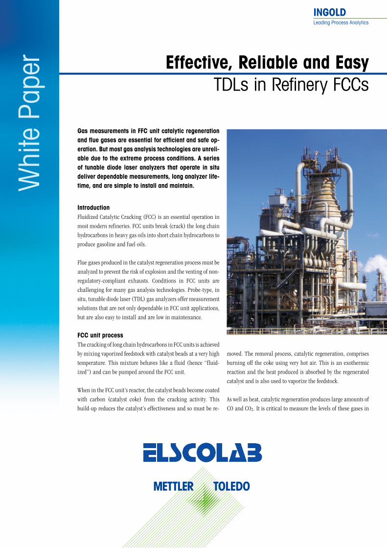
IntroductionFluidized Catalytic Cracking (FCC) is an essential operation in most modern refineries. FCC units break (crack) the long chain hydrocarbons in heavy gas oils into short chain hydrocarbons to produce gasoline and fuel oils.
Flue gases produced in the catalyst regeneration process must be analyzed to prevent the risk of explosion and the venting of non-regulatory-compliant exhausts. Conditions in FCC units are challenging for many gas analysis technologies. Probe-type, in situ, tunable diode laser (TDL) gas analyzers offer measurement solutions that are not only dependable in FCC unit applications, but are also easy to install and are low in maintenance.
FCCunitprocessThe cracking of long chain hydrocarbons in FCC units is achieved by mixing vaporized feedstock with catalyst beads at a very high temperature. This mixture behaves like a fluid (hence “fluid-ized”) and can be pumped around the FCC unit.
When in the FCC unit’s reactor, the catalyst beads become coated with carbon (catalyst coke) from the cracking activity. This build-up reduces the catalyst’s effectiveness and so must be re-
moved. The removal process, catalytic regeneration, comprises burning off the coke using very hot air. This is an exothermic reaction and the heat produced is absorbed by the regenerated catalyst and is also used to vaporize the feedstock.
As well as heat, catalytic regeneration produces large amounts of CO and CO2. It is critical to measure the levels of these gases in

2 METTLERTOLEDO
Whi
te P
aper
the regenerator flue gas as well as the residual oxygen level, as all of these are indicative of the rate and temperature of regen-eration. If the regeneration rate is too fast and the temperature too high, the catalyst will become overheated and unwanted sintering may occur, with consequent reduction in efficiency and potential catalyst destruction. If the rate of regeneration is too low, then there will be insufficient oxidation of the carbon, lead-ing to poor catalyst activity and inefficient cracking.
The CO-rich flue gas from the regeneration step is routed through a steam-generating boiler (CO furnace) where the CO is burned as a fuel to generate steam for use in the refinery and also to comply with environmental regulations on flue gas ex-haust. Fuel (e.g., natural gas) may be added to the flue gas prior to the boiler to increase combustion efficiency.
Before it is vented to atmosphere, the flue gas may pass through an electrostatic precipitator (ESP) which removes particulates
through the use of high voltage static electric fields between a series of metal pipes and plates that charge and then strip the entrained particles from the gas.
Gas and organic compounds measure-ment is important in FCC units to moni-tor catalytic regeneration, and in the flue gas from the CO boiler to the ESP, both for environmental reasons and to prevent explosions in the ESP caused by the CO and the high voltages across the ESP’s plates.
COfurnaceSince there are a variety of complex chemicals in the petroleum feed, often including organic sulfur and nitrogen
compounds, the flue gas from an FCC unit usually contains a wide range of contaminants. These can include not only CO but also trace levels of aldehydes, cyanides, ammonia, sulfur diox-ide (SO2), plus oxides of nitrogen (NOx), metals and other par-ticulates. Typical legislation therefore usually specifies a wide range of emissions measurements for these flue gases, often including oxygen, CO and possibly CO2.
The exhaust gas from the regenerator unit (before the CO fur-nace) has the following typical composition:Carbon dioxide 10 – 20 %
Carbon monoxide 10 – 25 %
Oxygen < 1 %
Water vapor 1 %
Sulfur dioxide < 0.5 %
Nitrogen oxides < 0.1 %
Nitrogen balance
Reactor
535 °C1.72 barg
Flue gas
Flue gasCatalyst
finesseparator
Flue gas
Cata
lyst
fines
Flue
gas
Com
bust
ion
air
CO boiler
Catalyst fineshoppers
Regenerator
715 °C2.41 barg
Tota
lfe
edSt
m
Measurementpoint GPro 500
Gas analysis measurement points in FCC unit
3METTLERTOLEDO
The sample is very hot (circa 600 °C) and has a dust loading which is very high and includes many fine particles (typically down to 70 µm). Due to the sample conditions, careful thought must be given to the process adaptor type and materials of con-struction used.
ContinuousemissionsmonitoringAs mentioned, the flue gases from the CO boiler (or directly from the catalytic regenerator) are vented to the atmosphere after suitable scrubbing to remove dust and pollutants. The gas com-position will be similar to that of a typical incinerator flue gas:Carbon dioxide 10 – 20 %
Carbon monoxide < 1000 ppm(v)
Oxygen 1 – 5 %
Water vapor 10 – 15 %
Sulfur dioxide < 1000 ppm(v)
Nitrogen oxides < 500 ppm(v)
Nitrogen balance
The sample at this stage will have a moderate dust loading.
Emissions monitoring will be required which will typically in-clude CO, oxygen and again possibly SO2, NOx and opacity mea-surements. The choice of analyzer technologies and types will depend on user or regulation preferences, and the required haz-ardous area rating (refineries are invariably Zone 1 or Zone 2 {Class 1 Division 1 and Division 2} areas).
IssueswithgasanalyzersA number of analyzer technologies are in use on FCCs for gas measurement. Paramagnetic and non-dispersive infrared (NDIR) analyzers were initially employed but measurement re-sponse was slow due to sample conditioning and transportation times. Also, narrow tubing could easily become blocked with particulates and extractive sample cells fouled. This made these analyzer types high in maintenance if measurement reliability was to be preserved.
Many oxygen analyzers based on the paramagnetic principle have a measuring cell which is assembled using epoxy resins. These are susceptible to attack by traces of corrosives in the sample, eventually leading to premature failure of the cell.
Oxygen analyzers using electrochemical cells should not be con-sidered for these applications. The electrochemical cell uses an alkaline electrolyte which will be rapidly neutralized by the acidic contaminants in the sample gas, leading to cell exhaus-tion. If an electrochemical cell falls to zero output (i.e. 0% oxy-gen) this would constitute “failure to danger” on any safety application.
The majority of CO combustion sensors in common use are based on pellistor technology, but these are also not without their issues. They are prone to measurement errors due to the two pellistor beads not being perfectly matched, radiative heat loss from each bead being different, and dirt in the gas building up on the sample pellistor but not on the reference. But their biggest issue is poor selectivity to CO, which can make measurements from such sensors highly unreliable.
AgasanalyzertechnologythatisfitforpurposeTunable diode laser (TDL) analyzers offer a modern approach to gas measurement in FCCs that overcomes the drawbacks of the above sensors. TDL analyzers work on the principle of laser ab-sorption spectroscopy. A focused and tunable laser beam is used to analyze absorption lines that are characteristic of the particu-lar gas species to be measured. TDLs usually measure in situ or directly from the gas stream without any sampling or conditioning.
TDL analyzers for process applications have two basic design types, namely cross-stack and probe-type. In the cross-stack design, the laser source is placed on one side of the pipe or duct and the receiver on the other. The wider the pipe diameter, the more difficult it is to align the laser source and receiver. In
Whi
te P
aper

Visit for more informationMettler-ToledoAGProcess AnalyticsIm Hackacker 15CH-8902 UrdorfSwitzerland
© 04/ 2 015
www.mt.com/pro
probe-type TDL analyzers, the defining feature is the sensor probe that protrudes into the process gas stream. The laser source and the detector are contained in a single unit, requiring a single flange connection.
Compact,reliable,accurateandlowmaintenanceTDLsMETTLER TOLEDO’s GPro 500 is a series of compact, probe-type TDL O2, CO CO2 and water vapor gas analyzers. They are highly suited to the conditions found in FCC units as they can be used with sample gases which contain corrosive traces and which are highly flammable. The range carries Optical Intrinsic Safety (OPIS) certification, meaning that the analyzers do not create optical energy of a sufficient magnitude to cause an explosion. The measurement performance offered on GPro 500s is also superior to other technologies, particularly in stability and rejec-tion of measurement interferences.
The series is available with a variety of adaptions that enable a very wide range in both application use and point of insertion. These adaptions include a sintered metal filter and baffle for hot and dusty applications such as catalytic regeneration, and a wafer cell for use in pipes as narrow as DIN 50.
Whi
te P
aper
Where an extractive solution is preferred or required (due to more extreme process conditions) the GPro 500 can be config-ured with an extractive cell.
Unlike other gas analyzer technologies, GPro 500 analyzers have no moving parts, and other than annual verification, require no maintenance.
ConclusionFluidized Catalytic Cracking units are found in most modern refineries and effective FCC unit operations are reliant on de-pendable gas measurements from resilient analyzers. METTLER TOLEDO’s GPro 500 range of robust, in situ gas analyzers deliver highly stable O2, CO, and CO2 measurements in regenerators and flue gas. Their compactness, modularity and extremely low maintenance make them the ideal choice for FCC unit applications.
cwww.mt.com/TDL
INGOLDLeading Process Analytics
Whi
te P
aper
Oncealmosttheexclusivedomainofzirconiumoxideandrudimentarycatalyticcombustionsensors, tun-ablediodelasers(TDLs)arequicklybecomingestab-lishedas thebestavailable technique(BAT) forO2andspecificCOanalysisfortheoptimizationofcom-bustionprocesses.Whereastraditionaltechnologieshavesuffered fromvariableperformanceandshortsensorlifetime,theinherentreliability,superiorper-formance,andspeedofresponseofTDLscombinetoofferanincreasinglyattractivealternative.
Don‘tGetBurnedinCombustionHigh Efficiency TDL Analyzers
IntroductionThere are literally tens of thousands of combustion processes in operation globally, ranging from small to medium scale waste incinerators right the way up to large scale power plants. Indus-tries as diverse as refining and petrochemicals, chemical inter-mediates, power generation, and iron and steel production utilize a variety of furnaces, boilers, kilns, process fired heaters, incinerators, and thermal oxidizers in their operations. Each of these combustion processes requires reliable oxygen measure-ments to ensure operating safety and to maximize efficiency. In addition, tight oxygen control leads to significantly reduced fuel costs and reduction in atmospheric emissions of undesirable combustible and greenhouse gases.
Achieving these goals requires a totally reliable, accurate and low maintenance analyzer that is able to operate continuously with minimal user intervention.

High
Effi
cien
cy T
DL A
naly
zers
2 METTLERTOLEDOWhite Paper
OxygenonlycontrolWhen the combustion process utilizes an oxygen-only measure-ment approach, the ideal excess air level of the system is usually determined first by modelling, or from data supplied by the manufacturer of the burner or furnace. The operator then runs the process at a slightly higher level of excess air (slightly air rich) to ensure a safety margin. The amount by which the excess air is increased beyond the ideal value will be largely dependent on the confidence that the operator has in the oxygen analysis. Therefore, having a reliable and accurate oxygen measurement is crucial in order to ensure highest efficiency while maintaining safety. If there is uncertainty in the oxygen measurement, it is typical to run the process excessively air rich, with significantly increased cost implications due to the requirement for additional fuel.
To highlight the costs involved in running an inefficient com-bustion process, the following estimate can be used as a general guide.
For every 1.5 % excess O2 ~ 1 % added fuel costFor every 0.2 % excess CO ~ 1 % added fuel cost
For large scale combustion processes, these costs can be enor-mous. Running the operation at maximum efficiency means the initial purchase and installation costs of the analysis equipment can be recovered in just a few months of operation.
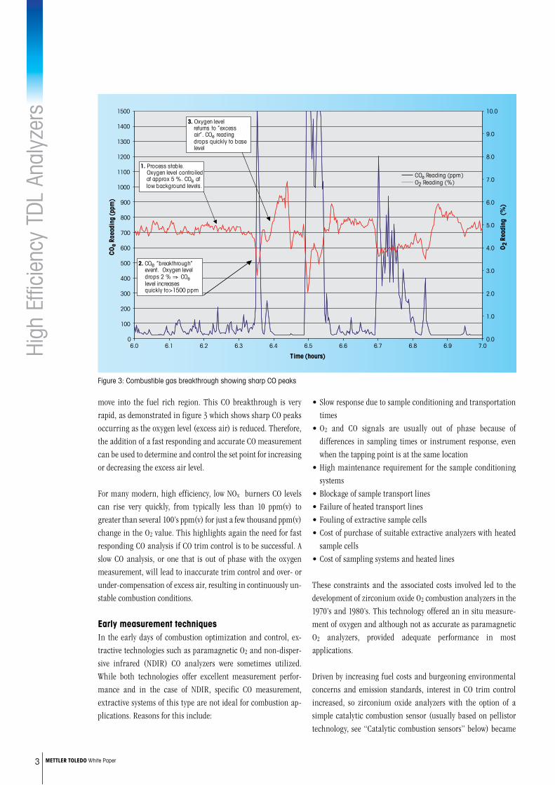
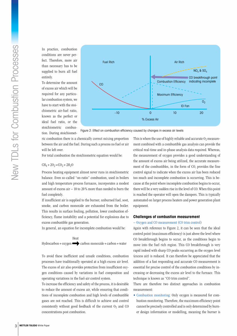
OxygenandCOmeasurement(COtrimcontrol)Increasingly, combustible gas measurements are also being added in combination with oxygen measurement, to further im-prove efficiency and reduce atmospheric emissions by providing the option of CO trim control. Again, with reference to figure 1, it can be seen that the ideal control point (maximum efficiency) is just above the level where CO breakthrough begins to occur as the conditions begin to
CombustionefficiencyEfficient combustion is essential for ensuring plant safety and to minimize atmospheric emissions. It also offers enormous poten-tial for cost savings by ensuring neither a fuel rich nor excessively air rich condition exists in the burner. A fuel rich condition is wasteful of fuel, creates additional safety issues, and also creates increased CO emissions. While an air rich condition leads to excess cooling, which results in inefficient combustion and the increased generation of NOx and SOx emissions.
Figure 1 demonstrates an idealized combustion efficiency curve. It can be seen that maximum combustion efficiency is achieved when just sufficient excess air is present to ensure complete combustion. The objective is therefore to achieve the lowest ex-cess air value possible, but with a safety margin to ensure that the combustion can never move over the “crossover” point to become fuel rich, indicated by a breakthrough of CO.
The above situation would apply in a static system, i.e., where the fuel type / quality, the ambient conditions, and the loading of the burner never vary. Of course, in reality, some or all of these pa-rameters will change, with the result that the crossover point and therefore the optimum level of excess air to ensure maximum efficiency, can dramatically change. Figure 2 demonstrates how changing parameters affect the combustion efficiency curve, effectively shifting the point of maximum efficiency and the crossover point.
Factors affecting the crossover point include:• Changes to fuel composition / type and heating value• Density changes of the fuel• Load variation• Changes in atmospheric conditions, particularly humidity, affecting the air used for combustion• Condition of the burners (fouling)• General wear of the entire combustion system
Fuel rich Air rich
–10 0 10 20
% Excess air
NOx & SOx
Maximum efficiency
Combustion efficiency CO
O2
Fuel rich Air rich
NOx & SOx
Maximum efficiency
Combustion efficiency CO
O2
Figure 1: Combustion efficiency curve (static system)
Fuel richincomplete combustion
Air richcomplete combustion
NOx & SOx
Combustion efficiency
Combustibles O2
Fuel richincomplete combustion
Air richcomplete combustion
Com
NOx & SOx
Combustion efficiency
mbustibles O2
Figure 2: Changing combustion conditions
High
Effi
cien
cy T
DL A
naly
zers
3 METTLERTOLEDOWhite Paper
move into the fuel rich region. This CO breakthrough is very rapid, as demonstrated in figure 3 which shows sharp CO peaks occurring as the oxygen level (excess air) is reduced. Therefore, the addition of a fast responding and accurate CO measurement can be used to determine and control the set point for increasing or decreasing the excess air level.
For many modern, high efficiency, low NOx burners CO levels can rise very quickly, from typically less than 10 ppm(v) to greater than several 100’s ppm(v) for just a few thousand ppm(v) change in the O2 value. This highlights again the need for fast responding CO analysis if CO trim control is to be successful. A slow CO analysis, or one that is out of phase with the oxygen measurement, will lead to inaccurate trim control and over- or under-compensation of excess air, resulting in continuously un-stable combustion conditions.
EarlymeasurementtechniquesIn the early days of combustion optimization and control, ex-tractive technologies such as paramagnetic O2 and non-disper-sive infrared (NDIR) CO analyzers were sometimes utilized. While both technologies offer excellent measurement perfor-mance and in the case of NDIR, specific CO measurement, extractive systems of this type are not ideal for combustion ap-plications. Reasons for this include:
• Slow response due to sample conditioning and transportation times• O2 and CO signals are usually out of phase because of differences in sampling times or instrument response, even when the tapping point is at the same location• High maintenance requirement for the sample conditioning systems• Blockage of sample transport lines• Failure of heated transport lines• Fouling of extractive sample cells• Cost of purchase of suitable extractive analyzers with heated sample cells• Cost of sampling systems and heated lines
These constraints and the associated costs involved led to the development of zirconium oxide O2 combustion analyzers in the 1970’s and 1980’s. This technology offered an in situ measure-ment of oxygen and although not as accurate as paramagnetic O2 analyzers, provided adequate performance in most applications.
Driven by increasing fuel costs and burgeoning environmental concerns and emission standards, interest in CO trim control increased, so zirconium oxide analyzers with the option of a simple catalytic combustion sensor (usually based on pellistor technology, see “Catalytic combustion sensors” below) became
0.0
1.0
2.0
3.0
4.0
5.0
6.0
7.0
8.0
9.0
10.0
0
100
200
300
400
500
600
700
800
900
1000
1100
1200
1300
1400
1500
6.0 6.1 6.2 6.3 6.4 6.5 6.6 6.7 6.8 6.9 7.0
O2
Read
ing
(%
)
CO
e Ra
eadi
ng (p
pm)
Time (hours)
2. COe “breakthrough” event. Oxygen level drops 2 % COe level increases quickly to>1500 ppm
3. Oxygen level returns to “excess air”. COe reading drops quickly to base level
1. Process stable. Oxygen level controlled at approx 5 %. COe at low background levels.
COe Reading (ppm)O2 Reading (%)
Figure 3: Combustible gas breakthrough showing sharp CO peaks

High
Effi
cien
cy T
DL A
naly
zers
4 METTLERTOLEDOWhite Paper
The necessity for high temperature heating of the sensor and the electrode design are the reasons for the inherent weakness of these sensors. The high temperature requirement creates mul-tiple failure modes, including:• Heater failure• Thermistor failure• Cracking (due to thermal shock) of the zirconia disc • Electrode peeling, i.e., the electrode detaches from the zirconia disc. This usually occurs under reducing conditions and particularly when the sensor is exposed to corrosive gases such a sulphur compounds
In addition to these catastrophic failure modes, the catalysts used on the disc surface can be readily poisoned or inhibited, causing the sensor to lose sensitivity and response, and normally requiring sensor replacement. Due to all these drawbacks, a typical zirconia oxygen sensor can be expected to last about three years maximum in operation, before replacement will be required. On more aggressive applications, this lifetime can be even shorter.
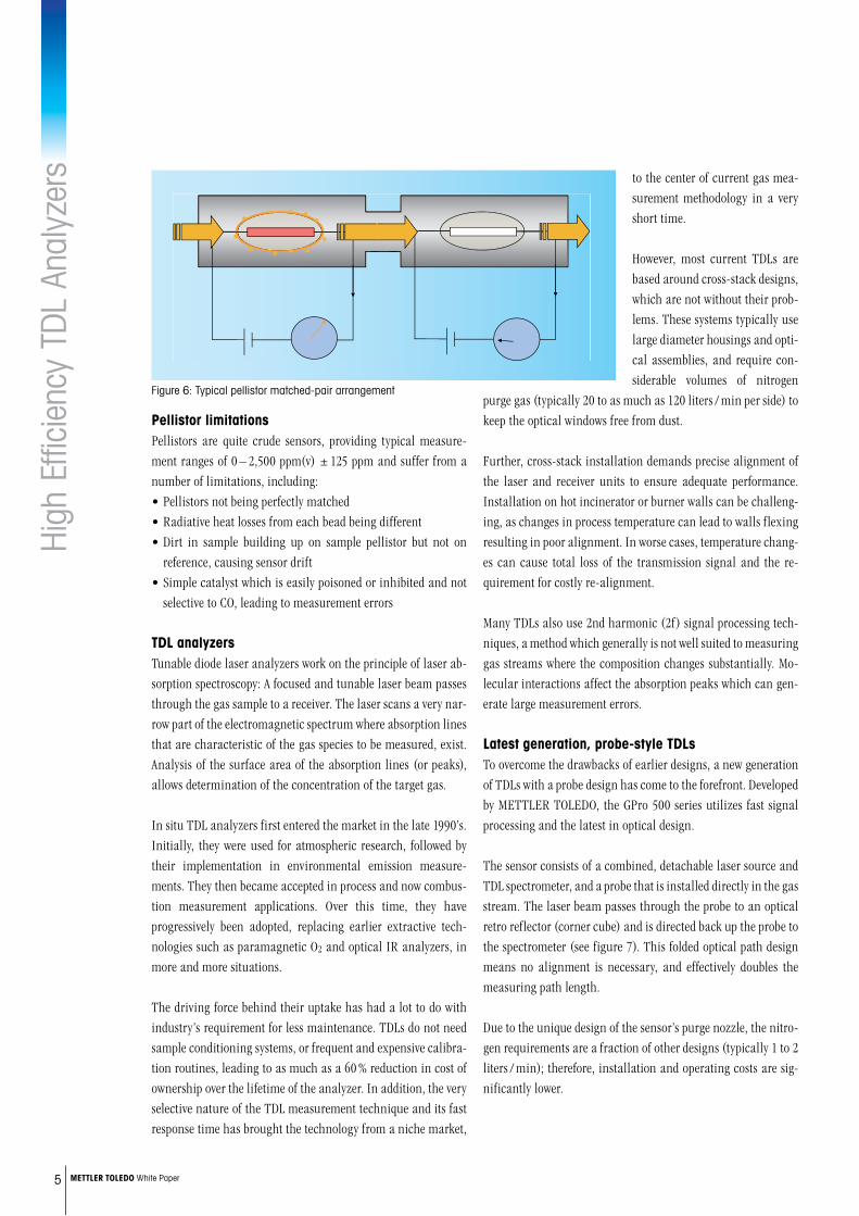
CatalyticcombustionsensorsThe majority of combustion sensors in common use are based on pellistor technology. A pellistor, also known as a catalytic or heated bead sensor, consists of either a single, or more com-monly a pair of matched precision resistors onto which two dif-ferent coating are applied (see figure 6). The first pellistor bead is coated with a catalyst that creates an exothermic reaction when exposed to combustible gases, principally, but not exclu-sively carbon monoxide. The second bead is covered with an inert (non-reactive) coating and is used as a reference to reduce tem-perature variations (due mainly to process flow) from generating errors in the measured value. In order to increase the reaction rate on the catalyst, the pellistors are typically heated to about 500 °C (930 °F). The pellistor pair is typically configured into a Wheatstone bridge.
available. This combination gave the advantage of O2 and com-bustion measurements that were in-phase and therefore such sensors became suitable for use in a trim control configuration for combustion optimization.
The problem with these simple combustion sensors is that they are generally very non-specific; in fact, they are often referred to as CO equivalent (COe) or simply combustion detectors. In effect, they are generally non-specific to carbon monoxide due to the very generic catalysts they use. Some manufacturers have at-tempted to improve sensor selectivity to CO, but at best they still offer relatively poor performance, which is explored in more detail below.
TraditionalsensortechnologyanditsdrawbacksZirconiumoxidesensorsIt is easiest to consider a zirconium oxide measuring cell as an oxygen balance. Zirconium oxide is a ceramic material and as such, is a good electrical insulator. For the cell to work, the in-herent resistance to electrical current flow must first be reduced. This is achieved by heating the zirconia to a high temperature. To accomplish this, the cell is fitted with an electrical heater, typically operating at a temperature of between 500 and 750 °C (932 and 1382 °F), depending on the application and type of electrode / catalyst used. The heater is normally controlled by an embedded thermistor.
To create the electrical circuit, two electrodes are bonded to the zirconium surface, one on each side, to allow connection of the cell output wires (see figure 5). In addition, the surface of the zirconium is coated with a suitable catalytic material to enable “tunnelling” of oxygen ions through the zirconium. The catalyst is often combined with the electrode in a single coating material. This coating is critical, as it must provide a reliable electrical connection and permanent bond to the zirconium, while re-maining porous to oxygen ions.
Zirconia disc Heater
Electrode
Sampleside
O2
O2
O2
O2
O2
O2
O2
O2
O2
O2Referenceside
Figure 4: Typical zirconium oxygen sensor
Stabilized zirconium
oxide
Cell heaterTemperature sensor
Electrodes
Sampleside
O2O2 O2
O2 O2
O2
O2
O2
O2O2
Referenceside
Cell output
e–
e–
e–
e–
e–
e–
O2–
O2–
Figure 5: Zirconium sensor electrical circuit
High
Effi
cien
cy T
DL A
naly
zers
5 METTLERTOLEDOWhite Paper
to the center of current gas mea-surement methodology in a very short time.
However, most current TDLs are based around cross-stack designs, which are not without their prob-lems. These systems typically use large diameter housings and opti-cal assemblies, and require con-siderable volumes of nitrogen
purge gas (typically 20 to as much as 120 liters / min per side) to keep the optical windows free from dust.
Further, cross-stack installation demands precise alignment of the laser and receiver units to ensure adequate performance. Installation on hot incinerator or burner walls can be challeng-ing, as changes in process temperature can lead to walls flexing resulting in poor alignment. In worse cases, temperature chang-es can cause total loss of the transmission signal and the re-quirement for costly re-alignment.
Many TDLs also use 2nd harmonic (2f) signal processing tech-niques, a method which generally is not well suited to measuring gas streams where the composition changes substantially. Mo-lecular interactions affect the absorption peaks which can gen-erate large measurement errors.
Latestgeneration,probe-styleTDLsTo overcome the drawbacks of earlier designs, a new generation of TDLs with a probe design has come to the forefront. Developed by METTLER TOLEDO, the GPro 500 series utilizes fast signal processing and the latest in optical design.
The sensor consists of a combined, detachable laser source and TDL spectrometer, and a probe that is installed directly in the gas stream. The laser beam passes through the probe to an optical retro reflector (corner cube) and is directed back up the probe to the spectrometer (see figure 7). This folded optical path design means no alignment is necessary, and effectively doubles the measuring path length.
Due to the unique design of the sensor’s purge nozzle, the nitro-gen requirements are a fraction of other designs (typically 1 to 2 liters / min); therefore, installation and operating costs are sig-nificantly lower.
PellistorlimitationsPellistors are quite crude sensors, providing typical measure-ment ranges of 0 – 2,500 ppm(v) ± 125 ppm and suffer from a number of limitations, including:• Pellistors not being perfectly matched• Radiative heat losses from each bead being different• Dirt in sample building up on sample pellistor but not on reference, causing sensor drift• Simple catalyst which is easily poisoned or inhibited and not selective to CO, leading to measurement errors
TDLanalyzersTunable diode laser analyzers work on the principle of laser ab-sorption spectroscopy: A focused and tunable laser beam passes through the gas sample to a receiver. The laser scans a very nar-row part of the electromagnetic spectrum where absorption lines that are characteristic of the gas species to be measured, exist. Analysis of the surface area of the absorption lines (or peaks), allows determination of the concentration of the target gas.
In situ TDL analyzers first entered the market in the late 1990’s. Initially, they were used for atmospheric research, followed by their implementation in environmental emission measure-ments. They then became accepted in process and now combus-tion measurement applications. Over this time, they have progressively been adopted, replacing earlier extractive tech-nologies such as paramagnetic O2 and optical IR analyzers, in more and more situations.
The driving force behind their uptake has had a lot to do with industry’s requirement for less maintenance. TDLs do not need sample conditioning systems, or frequent and expensive calibra-tion routines, leading to as much as a 60 % reduction in cost of ownership over the lifetime of the analyzer. In addition, the very selective nature of the TDL measurement technique and its fast response time has brought the technology from a niche market,
Figure 6: Typical pellistor matched-pair arrangement

High
Effi
cien
cy T
DL A
naly
zers
For more informationwww.mt.com/proMettler-ToledoAG
Process AnalyticsIm Hackacker 15CH-8902 UrdorfSwitzerland
© 04/2013
The direct absorption spectroscopy (DAS) measurement tech-nique that the GPro 500 series uses does not suffer from the same background gas errors as seen with 2f systems. This powerful signal processing method is combined with an in-built spectral database, enabling a real-time reference of the measurement gas peaks, and ensuring that the laser is always locked to the correct part of the spectrum. With SpectraID™ technology, three con-secutive absorption peaks are analyzed in height, relative posi-
tion and area. These results are then compared with a physical model of the absorption lines stored in the spectral database. If there is a a positive correlation between the two sets of data, then there is a perfect “DNA match” and it can be concluded that the observed absorption peaks are fully identified. This unique ap-proach provides absolute confidence in measurement integrity.
ConclusionTunable diode laser analyzers are now at the forefront of gas analysis and are increasingly the first choice for a growing num-ber of applications which were once the domain of extractive gas analyzers. TDLs are increasingly challenging zirconium oxide and catalytic technologies on combustion applications, where their low cost of installation and maintenance, fast response time, and reliability have cemented their reputation. A new gen-eration of probe-style TDLs are available, which take the core benefits of TDL technology, but overcome the earlier drawbacks of high purge gas flow and alignment difficulties to provide a truly flexible, easy to install, compact, and reliable solution.
4www.mt.com/o2-gas
GPro 500 TDL oxgen sensor
Figure 7: Modern, probe-style TDL, GPro 500
INGOLDLeading Process Analytics
Whi
te P
aper
Combustion processes are an integral operation inrefineries,petrochemical,fertilizer,andpowerplantsacross the globe. Rising fuel costs and increasingcompetition are driving plants to adopt new tech-niquesformeasuringcombustiblegaseswiththegoalofoptimizingtheircombustionprocesses.Leadingthepackistunablediodelaser(TDL)technology.Anewgeneration of TDLs not only offers exceptional fuelcosts savings, but eliminates the need for processsidepurgegas.
NoMorePurgeGasNew TDLs for Combustion Processes
IntroductionRefineries, petrochemical, fertilizer and power plants worldwide have large numbers of combustion processes in operation, from process heaters and fired heaters to package boilers and large steam turbines. Whenever a process fluid needs to be heated as part of a chemical reaction, or there is a requirement for steam generation, there will be a combustion process at its heart.
This paper presents a review of the general anatomy of a typical combustion process; describing each zone and its function, before discussing some of the challenges of combustion mea-surement and how modern TDL analyzers such as METTLER TOLEDO’s GPro 500 and its range of process adaptions offer many advantages over typical combustion analysis technologies. Finally, a selection of specific combustion applications will be described, highlighting the typical process conditions. These applications are ideal candidates for superior TDL combustion measurement.

New
TDL
s fo
r Com
bust
ion
Proc
esse
s
2 METTLERTOLEDOWhite Paper
5. Electrostatic precipita-tors remove particles from the gas stream using elec-trostatically charged plates. The operation of this device is covered in more detailed in our white paper covering non-combustion CO appli-cations for the GPro 500 TDL. To recap, fast response CO measurement is often a requirement to ensure that flammable gases do not reach the electrostatic plates, and therefore reduce explosion risk.
6. The ID fan is used to ensure there is a forced velocity of cleaned gas fed to the stack to ensure good dispersion.
7. Finally, the stack ensures that the cleaned flue gas is dis-charged well above ground level for atmospheric dispersion.
UnderstandingthecombustionprocessThe whole purpose of measuring combustion gases is to optimize the efficiency of the combustion process and therefore reduce fuel costs and also reduce wear to plant and equipment. To un-
derstand efficient opera-tion, the process of combus-tion should first be understood.Stable combustion condi-tions require the right amounts of fuel and oxy-gen. The combustion prod-ucts are heat energy, carbon
dioxide, water vapor, nitrogen, and other gases (excluding oxy-gen). In theory, there is a specific amount of oxygen needed to completely burn a given amount of fuel.
The famous combustion triangle tells us that for combustion to occur we need three things:
Fuel (hydrocarbon) + oxidant (oxygen) CO2 + waterHeat
If we have complete combustion, a chemical equation to describe this process would be:
Methane (CH4) + O2 (oxygen) Carbon dioxide (CO2) + water (H2O)
Heat
AnatomyofageneralcombustionprocessIn the above diagram we have seven general zones that follow a linear procession from the combustion zone to the emission stack.1. The combustion zone is where the burners are located and as
the name suggests, this is where the highest temperatures are to be found. For some applications temperatures can reach 1,200 – 1,500 °C (2,191 – 2,732 °F). Depending on the capacity, there may be multiple burners.
2. The heating zone or radiant section (sometimes called the firebox) is the region directly above the burners. Temperatures here can be typically 700 – 1,200 °C (1,292 – 2,191 °F). In the case of fired heaters, in this section there will be radiant tubes where the compound to be heated will be exposed to the high-est temperatures.
3. The super heater is a device that superheats steam and will be typically found in steam reformers. Its main purpose is to increase the temperature of saturated steam without raising its pressure.
4. Economizers are used to recover some of this heat from the combustion. Stack economizers are utilized to increase efficiency when large amounts of makeup water are used (e.g. when not all condensate is returned to the boiler or large amounts of steam is consumed in the process, so there is no condensate to return) or there is a simultaneous need for large quantities of hot water for some other use. Savings potential is based on the existing stack temperature, the volume of make-up water needed, and the hours of operation. Economizers are available in a wide range of sizes, from small coil-like units to very large waste heat recovery boilers.
Figure 1: Diagram of a generic combustion process
Stack
Com
bust
ion
Zone
Hea
ting
Zone
Econ
omiz
er
SuperHeater
ID FanElectrostaticPrecipitators
O2
CO
Oxyg
en Heat
Fuel
New
TDL
s fo
r Com
bust
ion
Proc
esse
s
3 METTLERTOLEDOWhite Paper
In practice, combustion conditions are never per-fect. Therefore, more air than necessary has to be supplied to burn all fuel entirely. To determine the amount of excess air which will be required for any particu-lar combustion system, we have to start with the stoi-chiometric air-fuel ratio, known as the perfect or ideal fuel ratio, or the stoichiometric combus-tion. During stoichiomet-ric combustion there is a chemically correct mixing proportion between the air and the fuel. During such a process no fuel or air will be left over.For total combustion the stoichiometric equation would be:
CH4 + 2O2 =CO2 + 2H2O
Process heating equipment almost never runs in stoichiometric balance. Even so-called “on-ratio” combustion, used in boilers and high temperature process furnaces, incorporates a modest amount of excess air – 10 to 20 % more than needed to burn the fuel completely.If insufficient air is supplied to the burner, unburned fuel, soot, smoke, and carbon monoxide are exhausted from the boiler. This results in surface fouling, pollution, lower combustion ef-ficiency, flame instability and a potential for explosions due to excess combustible gas generation.In general, an equation for incomplete combustion would be:
Hydrocarbon + oxygen carbon monoxide + carbon + water Heat
To avoid these inefficient and unsafe conditions, combustion processes have traditionally operated at a high excess air level. The excess of air also provides protection from insufficient oxy-gen conditions caused by variations in fuel composition and operating variations in the fuel-air control system.To increase the efficiency and safety of the process, it is desirable to reduce the amount of excess air, while ensuring that condi-tions of incomplete combustion and high levels of combustible gases are not reached. This is difficult to achieve and control consistently without good feedback of the current O2 and CO concentrations post combustion.
This is where the use of highly reliable and accurate O2 measure-ment combined with a combustible gas analysis can provide the critical real-time and in-phase analysis data required. Whereas, the measurement of oxygen provides a good understanding of the amount of excess air being utilized, the accurate measure-ment of the combustibles, in the form of CO, provides the fine control signal to indicate when the excess air has been reduced too much and incomplete combustion is occurring. This is be-cause at the point where incomplete combustion begins to occur, there will be a very sudden rise in the level of CO. When this point is reached the operator will open the dampers. This is typically automated on larger process heaters and power generation plant equipment.
Challengesofcombustionmeasurement– Oxygen and CO measurement (CO trim control)Again with reference to Figure 2, it can be seen that the ideal control point (maximum efficiency) is just above the level where CO breakthrough begins to occur, as the conditions begin to move into the fuel rich region. This CO breakthrough is very rapid indeed with sharp CO peaks occurring as the oxygen level (excess air) is reduced. It can therefore be appreciated that the addition of a fast responding and accurate CO measurement is essential for precise control of the combustion conditions by in-creasing or decreasing the excess air level to the furnace. This technique is known as “CO trim control”. There are therefore two distinct approaches in combustion measurement:• Combustion monitoring: Only oxygen is measured for com-
bustion monitoring. Therefore, the maximum efficiency point cannot be precisely controlled and is only determined by burn-er design information or modelling, meaning the burner is
Figure 2: Effect on combustion efficiency caused by changes in excess air levels
CO breakthrough point indicating incomplete
Maximum Efficiency
% Excess Air
Combustion Efficiency
Air RichFuel Rich
ID Fan
CO
O2
NOx & SOx
–10 0 10 20
New
TDL
s fo
r Com
bust
ion
Proc
esse
s
4 METTLERTOLEDOWhite Paper
concentrations. All combustion applications will have variations in particulates or fly ash loading. Due to the heavy particulate (fly ash) present in the gas stream from some coal-fired instal-lations, special care should be exercised to investigate and un-derstand the concentration and type of particulates that may be present under these circumstances, to ensure that sufficient fil-tration of the sample is provided.
TheeconomicsofcombustioncontrolExample of typical savings on a typical battery of 6 gas-fired heaters:• Fuel costs for the production of 200 m BTU/hour energy per
heater: with unit price of 4 $ per m BTU/hour, the total amount is 7 m $ per heater per year.
• If excess air can be reduced by 1.5 % O2, the estimated savings on fuel will be 1 %, or 70,000 $ per heater/year.
• Considering total costs of ownership (equipment, installation, engineering, and spares for an estimated analyzer lifetime of 5 years) of 75,000 $ for one O2 and one CO analyzer per heater,
• The investment will be cash positive in 13 months, with a total 5-year return on investment of 275,000 $ per heater, or 1,65 m $ for the whole heater battery.
• Additional, collateral benefits are cost savings for significantly lower NOx and CO emissions.
The above example clearly demonstrates the significant eco-nomic drivers that focus the desire to optimize efficiency of combustion processes throughout the plant.
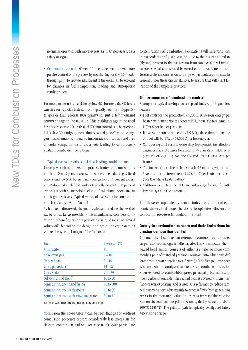
CatalyticcombustionsensorsandtheirlimitationsforprecisecombustioncontrolThe majority of combustion sensors in common use are based on pellistor technology. A pellistor, also known as a catalytic or heated bead sensor, consists of either a single, or more com-monly a pair of matched precision resistors onto which two dif-ferent coatings are applied (see figure 3). The first pellistor bead is coated with a catalyst that creates an exothermic reaction when exposed to combustible gases, principally but not exclu-sively carbon monoxide. The second bead is covered with an inert (non-reactive) coating and is used as a reference to reduce tem-perature variations (due mainly to process flow) from generating errors in the measured value. In order to increase the reaction rate on the catalyst, the pellistors are typically heated to about 500 °C (930 °F). The pellistor pair is typically configured into a Wheatstone bridge.
normally operated with more excess air than necessary, as a safety margin.
• Combustion control: Where CO measurement allows more precise control of the process by monitoring for the CO break-through point to provide adjustment of the excess air to account for changes in fuel composition, loading and atmospheric conditions, etc.
For many modern high efficiency, low NOx burners, the CO levels can rise very quickly indeed, from typically less than 10 ppm(v) to greater than several 100s ppm(v) for just a few thousand ppm(v) change in the O2 value. This highlights again the need for a fast response CO analysis if CO trim control is to be success-ful. A slow CO analysis, or one that is “out of phase” with the oxy-gen measurement, will lead to inaccurate trim control and over or under compensation of excess air leading to continuously unstable combustion conditions.
– Typical excess air values and dust loading considerationsLarge power plant boilers and process heaters can run with as much as 10 to 20 percent excess air, while some natural gas-fired boilers and low NOx burners may run as low as 5 percent excess air. Pulverized coal-fired boilers typically run with 20 percent excess air with some solid fuel coal-fired plants operating at much greater levels. Typical values of excess air for some com-mon fuels are shown in Table 1. As had been discussed, the goal is always to reduce the level of excess air as far as possible, while maintaining complete com-bustion. These figures only provide broad guidance and actual values will depend on the design and age of the equipment as well as the type and origin of the fuel used:
Fuel Excess air (%)
Anthracite 40Coke oven gas 5 – 10Natural gas 5 – 10Coal, pulverized 15 – 20Coal, stoker 20 – 30Oil (No. 2 and No. 6) 10 to 20Semi anthracite, hand firing 70 to 100Semi anthracite, with stoker 40 to 70Semi anthracite, with traveling grate 30 to 60
Table 1: Common fuels and excess air levels
Note: From the above table it can be seen that gas or oil-fired combustion processes require considerably less excess air for efficient combustion and will generate much lower particulate
New
TDL
s fo
r Com
bust
ion
Proc
esse
s
5 METTLERTOLEDOWhite Paper
OtherCOmeasurementtechniquesIn the past, nondispersive infrared (NDIR) CO ana-lyzers have sometimes been used for CO combustion measurement applications. While they can offer ex-cellent measurement performance and CO specific determination, most rely on extractive sample han-dling systems which can result in measurement and maintenance issues, including:• Slow response due to sample conditioning and
transportation times• O2 and CO signals being out of phase due to differ-
ences in sampling times or instrument response, even when the sample is drawn from the same location
• High maintenance requirements for the sample conditioning system
• Blockage of sample transport lines caused by particulate loading
• Failure of heated transport lines• Fouling of extractive sample cells• Cost of purchase of suitable extractive analyzers with heated
sample cells• Cost of sampling system and heated lines.
The above limitations have largely resulted in the demise of extractive NDIR analysis in the majority of combustion applications.
TheidealCOcombustionanalyzerTo guarantee the maximum integrity for the CO measurement, several things should be considered. These include:• In situ measurement not requiring a sample handling
system• CO specific measurement versus a non-specific total combus-
tibles measurement.• Accuracy of the combustibles measurement• Speed of response• In-phase measurement• Reliability • Sensor lifetime
In comparison with the many drawbacks and technical compro-mises of catalytic sensors and extractive NDIR technology, a modern, in situ, probe-type TDL, such as METTLER TOLEDO’s GPro 500 series, offers considerable measurement, operational,
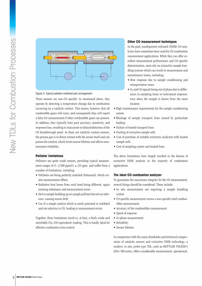
These sensors are non-CO specific. As mentioned above, they operate by detecting a temperature change due to combustion occurring on a catalytic surface. This means, however, that all combustible gases will react, and consequently they will report a false CO measurement if other combustible gases are present. In addition, they typically have poor accuracy, sensitivity, and response time, resulting in inaccurate or delayed detection of the CO breakthrough point. As these are catalytic contact sensors, the process gas is in direct contact with the sensor itself and can poison the catalyst, which limits sensor lifetime and affects mea-surement reliability.
PellistorlimitationsPellistors are quite crude sensors, providing typical measure-ment ranges of 0 – 2,500 ppm(v) ± 125 ppm, and suffer from a number of limitations, including:• Pellistors not being perfectly matched (balanced), which cre-
ates measurement offsets• Radiative heat losses from each bead being different, again
creating imbalance and measurement errors• Dirt in sample building up on sample pellistor but not on refer-
ence, causing sensor drift• Use of a simple catalyst which is easily poisoned or inhibited
and not selective to CO, leading to measurement errors.
Together, these limitations result in, at best, a fairly crude and unreliable COe (CO equivalent) reading. This is hardly ideal for effective combustion trim control.
Figure 3: Typical pellistor matched-pair arrangement
New
TDL
s fo
r Com
bust
ion
Proc
esse
s
6 METTLERTOLEDOWhite Paper
and cost benefits. Table 2 highlights the advantages that a high integrity, CO-specific TDL measurement provides for accurate and reliable combustion control measurement.
Catalytic com- In situ probe type
bustion sensor TDL CO analyzer
CO specific no yesAccuracy poor highSensitivity low highSpeed of response average fastPoisoning of sensor possible noReliability average extremely highSensor lifetime 1 – 2 years 10+ years
Table 2: Comparison of catalytic combustion sensor with TDL analyzer
One significant challenge for TDL analyzers, particularly for combustion monitoring or control applications, has been the significant consumption of purge gas to protect the analyzer’s optical windows. Even though probe-type TDLs reduce purge gas consumption considerably compared with earlier cross-stack de-signs (and eliminate the need to align the sender and receiver units), this can still be a constraint, particularly for retrofit installations.
This limitation has been overcome by the release of a range of innovative process adaptions designed to augment the already high performance measurement of the GPro 500 TDL.
Figures 4, 5, and 6 illustrate the design of the GPro 500 and the variety of available process adaptions. These process adaptions offer an interface solution for a wide range of applications, creat-
Figure 4: The range of process adaptions available for the GPro 500 TDL series.
ing a fully flexible measurement solution, and allowing success-ful installation of TDLs into processes and locations once thought impractical, or even impossible.
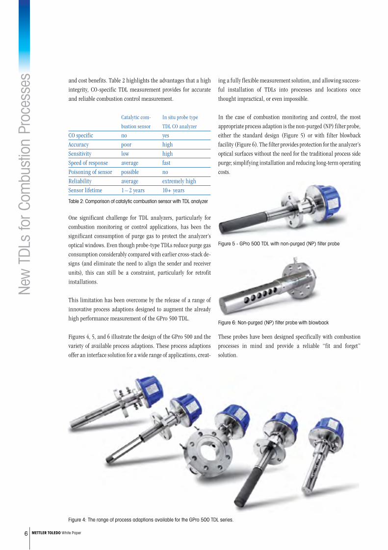
In the case of combustion monitoring and control, the most appropriate process adaption is the non-purged (NP) filter probe, either the standard design (Figure 5) or with filter blowback facility (Figure 6). The filter provides protection for the analyzer’s optical surfaces without the need for the traditional process side purge; simplifying installation and reducing long-term operating costs.
These probes have been designed specifically with combustion processes in mind and provide a reliable “fit and forget” solution.
Figure 5 - GPro 500 TDL with non-purged (NP) filter probe
Figure 6: Non-purged (NP) filter probe with blowback

New
TDL
s fo
r Com
bust
ion
Proc
esse
s
7 METTLERTOLEDOWhite Paper
for in situ, probe-type TDL analyzers, where their compact size, single flange entry, and probe configuration allow di-rect installation in place of traditional ZrO2/com-bustion analyzers. The typical installation point will be at the boiler or economizer outlet.
2)ProcessheatersThe term “process heater” commonly refers to any process in the plant
which directly employs hot combustion gases to raise the tem-perature of a gas or liquid process stream. Process heaters are, in effect, heat exchangers and are used extensively throughout refineries and petrochemical plants. They are the main consum-ers of fuel on site and are therefore a major focus for combustion efficiency optimization.
Process heaters consist of multiple coils of tubes inside of which the process fluid passes. Typically, in a refinery this will be a liquid hydrocarbon stream which needs to be heated to a set temperature before entering a refining stage of the plant. The stream is heated by heat exchange with the hot flue gases as these rise through the heater, and also directly by heat from the burners in the radiant section of the heater.
Combustionprocesssystems1)PackageboilersA package boiler refers typically to relatively small scale, pre-designed or “off the shelf” boilers which are available in a large number of types and capacities. Due to their optimized designs they are very efficient and typically use less fuel and electric power to operate than non-integrated designs. They are therefore commonly used in a large variety of applications in the food, light industrial, pharmaceutical, food, ceramic, and associated industries.
Just as with other combustion process units, a package boiler operates more efficiently when the excess air concentration in the flue gas is reduced while always ensuring that incomplete combustion is avoided. Optimizing air intake for boiler opera-tion requires continuous measurement of the oxygen concentra-tion in the flue gas.
The typical package boiler is a water tube boiler or flue and smoke tube boiler with a capacity of 5 to 20 t/h (average steam generation capacity). The most widely used fuels are heavy oil, light oil, and gas.
Gas temperature 150 to 300 °C (302 to 572 °F)Gas pressure ± 0.5 kPa (– 0.07 to 0.07 psi)Dust loading ≤ 1 g / Nm3
Fuel Fuel oil, kerosene or gas
Table 3: Typical process conditions in a package boiler
It can be seen from Table 3 that the typical flue gas conditions encountered in the average package boiler are not extreme, with flue temperatures circa 300 °C. This is an excellent application
Figure 7: Diagram of typical package boiler
Chimney
Steam at 150°C
200°C
Water
Water
350°C
Burner
3rd pass (tubes)
2nd pass (tubes)
1st pass [furnance tube(s)]
Steam space
O2
Figure 8: Diagram of a typical process heater
Stack TempDraft Gauge
Damper
Radiant Tubes
Crossover
Draft Gauge
Bridgewall
BurnersFeed Stock out
Feed Stock in
Crosso
CO O2
New
TDL
s fo
r Com
bust
ion
Proc
esse
s
8 METTLERTOLEDOWhite Paper
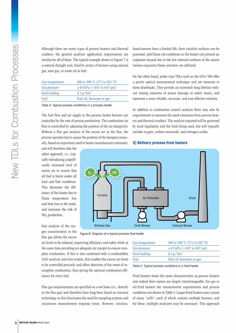
Although there are many types of process heaters and thermal crackers, the general analyzer application requirements are similar for all of them. The typical example shown in Figure 7 is a natural draught unit, fired by arrays of burners using natural gas, sour gas, or waste oil as fuel.
Gas temperature 300 to 500 °C (572 to 932 °F)Gas pressure ± 0.5 kPa (– 0.07 to 0.07 psi)Dust loading ≤ 1 g / Nm3
Fuel Fuel oil, kerosene or gas
Table 4: Typical process conditions in a process heater
The fuel flow and air supply to the process heater burners are controlled by the rate of process production. The combustion air flow is controlled by adjusting the position of the air damper(s). Without a flue gas analysis of the excess air in the flue, the process operator has to assess the position of the dampers manu-ally, based on experience and/or heater manufacturer estimates, and will therefore take the safest approach, i.e., typi-cally introducing a signifi-cantly increased level of excess air to ensure that all fuel is burnt under all load and fuel conditions. This decreases the effi-ciency of the heater due to flame temperature loss and heat loss to the stack, and increases the risk of NOx production. Fast analysis of the oxy-gen concentration in the flue gas allows the excess air levels to be reduced, improving efficiency and safety while at the same time providing an adequate air margin to ensure com-plete combustion. If this is also combined with a combustibles (CO) analyzer and trim system, this enables the excess air levels to be controlled precisely and offers detection of the onset of in-complete combustion, thus giving the optimal combustion effi-ciency for every fuel.
Flue gas measurements are specified on a wet basis (i.e., directly in the flue gas) and therefore have long been based on zirconia technology as this eliminates the need for sampling systems and minimizes measurement response times. However, zirconia-
based sensors have a limited life, their catalytic surfaces can be poisoned, and flame out conditions in the heater can present an explosion hazard due to the hot internal surfaces of the sensor (unless expensive flame arrestors are utilized).
On the other hand, probe-type TDLs such as the GPro 500 offer a purely optical measurement technique and are immune to these drawbacks. They provide an extremely long lifetime with-out raising concerns of sensor damage or safety issues, and represent a more reliable, accurate, and cost-effective solution.
In addition to combustion control analysis there may also be requirements to measure the stack emissions from process heat-ers and thermal crackers. The analysis required will be governed by local legislation and the fuels being used, but will typically include oxygen, carbon monoxide, and nitrogen oxides.
3)Refineryprocess-firedheaters
Gas temperature 300 to 500 °C (572 to 932 °F)Gas pressure ± 0.5 kPa (– 0.07 to 0.07 psi)Dust loading ≤ 1 g / Nm3
Fuel Fuel oil, kerosene or gas
Table 5: Typical process conditions in a fired heater
Fired heaters share the same characteristics as process heaters and indeed their names are largely interchangeable. For gas or oil-fired heaters the measurement requirements and process conditions are shown in Table 5. Larger fired heaters may consist of many “cells”, each of which contain multiple burners, and for these, multiple analyzers may be necessary. This approach
Figure 9: Diagram of a typical process fired heater
Window Box
FurnaceStack
Exhaust BlowerDraft Blower
Air Preheater
CO O2
New
TDL
s fo
r Com
bust
ion
Proc
esse
s
For more informationwww.mt.com/proMettler-ToledoAG
Process AnalyticsIm Hackacker 15CH-8902 UrdorfSwitzerland
© 01/2015
ensures that an analysis is dedicated to each bank of burners and their burner control system.
The critical performance parameters for both oxygen and com-bustibles measurement are speed of response (typically ≤ 10 s total for T90 is required), analyzer integrity, and measurement repeatability. In situ TDL analyzers are highly suited for use in fired heaters as they offer fast speed of response (< 2 sec), preci-sion long life measurement, specific CO determination, and are unaffected by catalyst poisons in the gas stream that can damage other sensors.
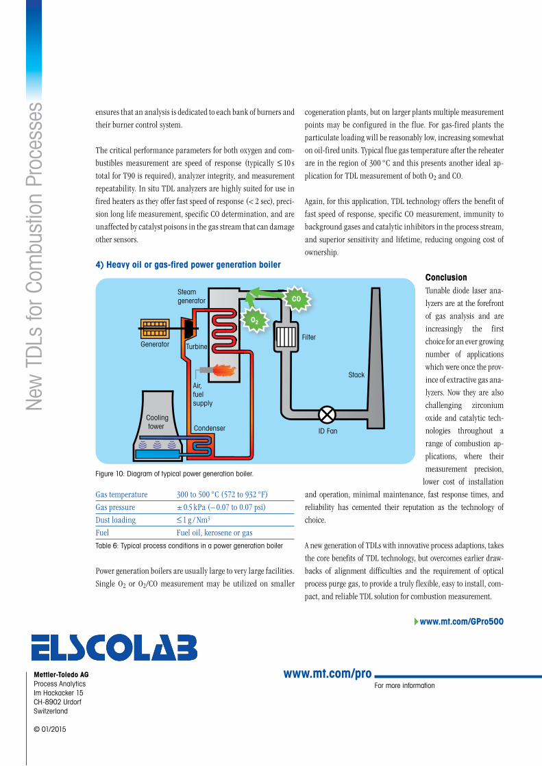
4)Heavyoilorgas-firedpowergenerationboiler
Gas temperature 300 to 500 °C (572 to 932 °F)Gas pressure ± 0.5 kPa (– 0.07 to 0.07 psi)Dust loading ≤ 1 g / Nm3
Fuel Fuel oil, kerosene or gasTable 6: Typical process conditions in a power generation boiler
Power generation boilers are usually large to very large facilities. Single O2 or O2/CO measurement may be utilized on smaller
cogeneration plants, but on larger plants multiple measurement points may be configured in the flue. For gas-fired plants the particulate loading will be reasonably low, increasing somewhat on oil-fired units. Typical flue gas temperature after the reheater are in the region of 300 °C and this presents another ideal ap-plication for TDL measurement of both O2 and CO. Again, for this application, TDL technology offers the benefit of fast speed of response, specific CO measurement, immunity to background gases and catalytic inhibitors in the process stream, and superior sensitivity and lifetime, reducing ongoing cost of ownership.
ConclusionTunable diode laser ana-lyzers are at the forefront of gas analysis and are increasingly the first choice for an ever growing number of applications which were once the prov-ince of extractive gas ana-lyzers. Now they are also challenging zirconium oxide and catalytic tech-nologies throughout a range of combustion ap-plications, where their measurement precision,
lower cost of installation and operation, minimal maintenance, fast response times, and reliability has cemented their reputation as the technology of choice.
A new generation of TDLs with innovative process adaptions, takes the core benefits of TDL technology, but overcomes earlier draw-backs of alignment difficulties and the requirement of optical process purge gas, to provide a truly flexible, easy to install, com-pact, and reliable TDL solution for combustion measurement.
4www.mt.com/GPro500
Figure 10: Diagram of typical power generation boiler.
Generator Turbine
Steamgenerator
Air,fuelsupply
CondenserCooling tower
Filter
Stack
ID Fan
O2
CO
INGOLD Leading Process Analytics
Due to its polluting effects, hydrogen chloride (HCl) levels in industrial exhausts are of growing concern. To ensure levels are within required limits, HCl mon-itoring equipment is installed on stacks and scrub-bers where the gas is present. However, measuring the gas can be very challenging with commonly used technologies. In situ, probe-type analyzers using tun-able diode laser spectroscopy offer a cost-effective, low maintenance and reliable alternative.
HCl Monitoring in Stacks and Scrubbers Now Has a Dependable Solution
Whi
te P
aper
The requirement for hydrogen chloride analysisThe most common non-sulfurous acid gas emitted from indus-trial processes is hydrogen chloride. It is a significant atmo-spheric pollutant which is harmful to human health and the environment. HCl contributes to acid rain and consequential damage to both infrastructure and agriculture. Common sourc-es of HCl in industrial exhausts include waste incineration and ethylene dichloride production. These processes generate signifi-cant volumes of HCl which must be reduced to very low levels before off-gases can be released to the atmosphere.
HCl is a pungent gas with a low odor threshold of 0.26 ppmv and has an Immediately Dangerous to Life and Health concentration of 50 ppmv. It has a National Institute for Occupational Safety and Health and Occupational Safety and Health Administration Permissible Exposure Limit of just 5 ppmv. Due to these hazards HCl release from fixed emission sources are increasingly moni-tored and controlled, and legislative emission levels apply in many countries.
The challenges of extractive measurement technologiesThere are several emission monitoring system technologies available that can be considered for the measurement of HCl, including extractive techniques such as non-dispersive infrared, gas filter correlation, fourier transform infrared and cavity ring-down spectroscopy. Each of these has their relative merits but all
share the same requirement: extraction and conditioning of a gas sample from the process to allow determination of HCl levels.
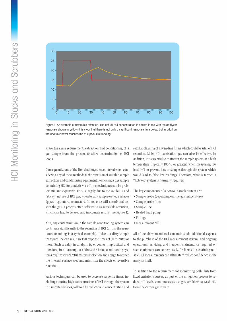
Consequently, one of the first challenges encountered when con-sidering any of these methods is the provision of suitable sample extraction and conditioning equipment. Removing a gas sample containing HCl for analysis via off-line techniques can be prob-lematic and expensive. This is largely due to the solubility and “sticky” nature of HCl gas, whereby any sample-wetted surfaces (pipes, regulators, rotameters, filters, etc.) will absorb and de-sorb the gas, a process often referred to as reversible retention, which can lead to delayed and inaccurate results (see Figure 1).
Also, any contamination in the sample conditioning system can contribute significantly to the retention of HCl (dirt in the regu-lators or tubing is a typical example). Indeed, a dirty sample transport line can result in T90 response times of 30 minutes or more. Such a delay in analysis is, of course, impractical and therefore, in an attempt to address the issue, conditioning sys-tems require very careful material selection and design to reduce the internal surface area and minimize the effects of reversible retention.
Various techniques can be used to decrease response times, in-cluding running high concentrations of HCl through the system to passivate surfaces, followed by reduction in concentration and
HCl M
onito
ring
in S
tack
s an
d Sc
rubb
ers
regular cleaning of any in-line filters which could be sites of HCl retention. Moist HCl passivation gas can also be effective. In addition, it is essential to maintain the sample system at a high temperature (typically 180 °C or greater) when measuring low level HCl to prevent loss of sample through the system which would lead to false low readings. Therefore, what is termed a “hot/wet“ system is normally required.
The key components of a hot/wet sample system are:• Sample probe (depending on flue gas temperature)• Sample probe filter• Sample line• Heated head pump• Fittings• Measurement cell
All of the above mentioned constraints add additional expense to the purchase of the HCl measurement system, and ongoing operational servicing and frequent maintenance required on such equipment can be very costly. Problems in sustaining reli-able HCl measurements can ultimately reduce confidence in the analysis itself. In addition to the requirement for monitoring pollutants from fixed emission sources, as part of the mitigation process to re-duce HCl levels some processes use gas scrubbers to wash HCl from the carrier gas stream.
2 METTLER TOLEDO White Paper
Figure 1: An example of reversible retention. The actual HCl concentration is shown in red with the analyzer
response shown in yellow. It is clear that there is not only a significant response time delay, but in addition,
the analyzer never reaches the true peak HCl reading.
_
_
_
_
_
_
_
30
25
20
15
10
5
00 10 20 30 40 50 60 70 80 90 100
– – – – – – – – – – – – – – – – – – – – – – – – – – – – – – – – – – – – – – – – – – – – – – – – – – – – – – – – – – – – – – – – – – – – – – – – – – – – – – – – – – – – – – – – – – – – – – – – – – – –
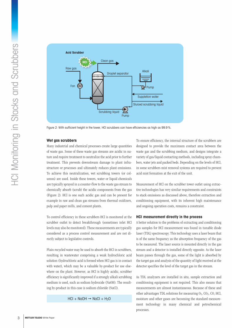
Wet gas scrubbersMany industrial and chemical processes create large quantities of waste gas. Some of these waste gas streams are acidic in na-ture and require treatment to neutralize the acid prior to further treatment. This prevents downstream damage to plant infra-structure or processes and ultimately reduces plant emissions. To achieve this neutralization, wet scrubbing towers (or col-umns) are used. Inside these towers, water or liquid chemicals are typically sprayed in a counter-flow to the waste gas stream to chemically absorb (scrub) the acidic components from the gas (Figure 2). HCl is one such acidic gas and can be present for example in raw and clean gas streams from thermal oxidizers, pulp and paper mills, and cement plants.
To control efficiency in these scrubbers HCl is monitored at the scrubber outlet to detect breakthrough (sometimes inlet HCl levels may also be monitored). These measurements are typically considered as a process control measurement and are not di-rectly subject to legislative controls. Plain recycled water may be used to absorb the HCl in scrubbers, resulting in wastewater comprising a weak hydrochloric acid solution (hydrochloric acid is formed when HCl gas is in contact with water), which may be a valuable by-product for use else-where on the plant. However, as HCl is highly acidic, scrubber efficiency is significantly improved if a strongly alkali scrubbing medium is used, such as sodium hydroxide (NaOH). The result-ing by-product in this case is sodium chloride (NaCl).
HCl + NaOH NaCl + H2O
To ensure efficiency, the internal structure of the scrubbers are designed to provide the maximum contact area between the waste gas and the scrubbing medium, and designs integrate a variety of gas/liquid contacting methods, including spray cham-bers, water jets and packed beds. Depending on the levels of HCl, in some scrubbers mist removal systems are required to prevent acid mist formation at the exit of the unit.
Measurement of HCl on the scrubber tower outlet using extrac-tive technologies has very similar requirements and constraints to stack emissions as discussed above, therefore extraction and conditioning equipment, with its inherent high maintenance and ongoing operation costs, remains a constraint.
HCl measurement directly in the processA better solution to the problems of extracting and conditioning gas samples for HCl measurement was found in tunable diode laser (TDL) spectroscopy. This technology uses a laser beam that is of the same frequency as the absorption frequency of the gas to be measured. The laser source is mounted directly in the gas stream and a detector is installed directly opposite. As the laser beam passes through the gas, some of the light is absorbed by the target gas and analysis of the quantity of light received at the detector specifies the level of the target gas in the stream.
As TDL analyzers are installed in situ, sample extraction and conditioning equipment is not required. This also means that measurements are almost instantaneous. Because of these and other advantages TDL solutions for measuring O2, CO2, CO, HCl, moisture and other gases are becoming the standard measure-ment technology in many chemical and petrochemical processes.
HCl M
onito
ring
in S
tack
s an
d Sc
rubb
ers
3 METTLER TOLEDO White Paper
Figure 2: With sufficient height in the tower, HCl scrubbers can have efficiencies as high as 99.9 %.
Sluiced scrubbing liquid
Suppletion water
Pump
Droplet separator
Clean gas
Raw gas
Fan
Acid Scrubber
Pump
Alkali
Scrubbing liquid
HCl
Commonly, TDL analyzers are of a cross-stack configuration as described above, i.e. separate laser source and detector installed on opposite sides of the stack, pipe or vessel. Such an arrange-ment requires the mounting of a flange on both sides of the stack and careful alignment of laser source and detector, plus there must be access to the two flanges.
Unfortunately, this “line of sight” configuration can have its issues. When the stack walls flex due to thermal expansion and contraction, the laser source and detector can become mis-aligned and in extreme cases the entire signal can be lost. The solution is to realign the beam or move the installation to a point where thermal conditions are less severe, but perhaps to a loca-tion where the gas stream is less representative of the target gas. In addition, high consumption of purge gas is required to keep the optical windows free of dust, particles and “sticky” hydrocarbons.
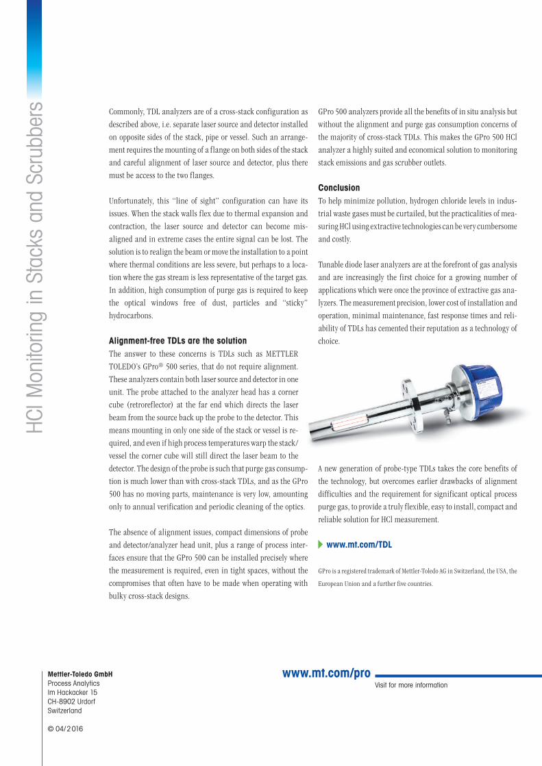
Alignment-free TDLs are the solutionThe answer to these concerns is TDLs such as METTLER TOLEDO’s GPro® 500 series, that do not require alignment. These analyzers contain both laser source and detector in one unit. The probe attached to the analyzer head has a corner cube (retroreflector) at the far end which directs the laser beam from the source back up the probe to the detector. This means mounting in only one side of the stack or vessel is re-quired, and even if high process temperatures warp the stack/vessel the corner cube will still direct the laser beam to the detector. The design of the probe is such that purge gas consump-tion is much lower than with cross-stack TDLs, and as the GPro 500 has no moving parts, maintenance is very low, amounting only to annual verification and periodic cleaning of the optics.
The absence of alignment issues, compact dimensions of probe and detector/analyzer head unit, plus a range of process inter-faces ensure that the GPro 500 can be installed precisely where the measurement is required, even in tight spaces, without the compromises that often have to be made when operating with bulky cross-stack designs.
GPro 500 analyzers provide all the benefits of in situ analysis but without the alignment and purge gas consumption concerns of the majority of cross-stack TDLs. This makes the GPro 500 HCl analyzer a highly suited and economical solution to monitoring stack emissions and gas scrubber outlets.
ConclusionTo help minimize pollution, hydrogen chloride levels in indus-trial waste gases must be curtailed, but the practicalities of mea-suring HCl using extractive technologies can be very cumbersome and costly.
Tunable diode laser analyzers are at the forefront of gas analysis and are increasingly the first choice for a growing number of applications which were once the province of extractive gas ana-lyzers. The measurement precision, lower cost of installation and operation, minimal maintenance, fast response times and reli-ability of TDLs has cemented their reputation as a technology of choice.
A new generation of probe-type TDLs takes the core benefits of the technology, but overcomes earlier drawbacks of alignment difficulties and the requirement for significant optical process purge gas, to provide a truly flexible, easy to install, compact and reliable solution for HCl measurement.
www.mt.com/TDL
GPro is a registered trademark of Mettler-Toledo AG in Switzerland, the USA, the
European Union and a further five countries.
HCl M
onito
ring
in S
tack
s an
d Sc
rubb
ers
Visit for more informationMettler-Toledo GmbHProcess AnalyticsIm Hackacker 15CH-8902 UrdorfSwitzerland
© 04/ 2 016
www.mt.com/pro