effective strains caused by different process conditions of...
TRANSCRIPT

Indian Journal of Engineering & Materials Sciences Vol. 22, December 2015, pp. 661-668
Effective strains caused by different process conditions of extrusion-shear and its
influences on the microstructures of AZ31 magnesium alloy
H-J Hua,b*, H Wanga, Y-Y Lia, M B Yanga & Zhongwen Oub aCollege of Material Science and Engineering, Chongqing University of Technology, Chongqing, 400050, China,
bPLA Chongqing Logistics Engineering College, 401311,China
Received 7 November 2014; accepted 18 June 2015
To improve strengths and microstructures evolution for magnesium alloy, extrusion-shear (ES) has been widely investigated because of its potentiality to produce ultra-fine grained microstructures of magnesium alloys. It is crucial to explore the effects of process parameters especially extrusion speeds and extrusion ratios on the deformation behaviors of magnesium alloy during ES process. Three-dimensional (3D) geometric models of ES processes with different extrusion speeds and extrusion ratios have been applied. Different extrusion speeds have been regarded as the initial conditions used
in DEFORMTM-3D software, and different extrusion ratios have been taken. The microstructures evolvements have been analyzed by the simulation and experimental results. The strains in the extruded rods have been predicted during ES process. ES process with different extrusion speeds and extrusion ratios have been applied to fabricate AZ31 magnesium alloy rod with preheated temperature 400°C. The strains of ES process slightly increase with the rise of extrusion speeds. Average grain sizes prepared by lower extrusion speeds are bigger than those prepared by higher speeds with the same die structures. The strains slightly decrease with the rise of extrusion ratios. The average sizes of microstructures for magnesium alloy prepared by ES extrusion decrease with the rise of extrusion ratios.
Keywords: Magnesium alloys, Microstructures, Grains refinement, Extrusion speed, Extrusion ratio
Magnesium alloy is the lightest of the structural metals. The ratio of strength to weight for the
magnesium alloys is comparable with that of the
strong alloys of aluminium or with the alloy steels, which is used when great strength is not necessary,
but where a thick, light form is desired1,2
. In recent
years bulk microstructure materials processed by methods of severe plastic deformation (SPD) such as
equal channel angular extrusion (ECAE) have
attracted the growing interest of specialists in
materials science3. ECAE usually includes more t
han 2 steps, and the material endures intricate
diversification of forming environments and may be
oxidized. Our research team engaged in the researches of the ES process, and the process include initial
forward extrusion and shearing process subsequently
as early as 20083,4
. The technology has been granted patents for Chinese inventions. Optimum extrusion
speeds and die structures for ES process could
improve satisfactory mechanical properties of
magnesium alloy. Effects of strain distributions on deformation characteristics can play a significant role
in the formation of ultra-fined grains (UFG) for
magnesium alloy, and which could affect the dislocation density and evolution of dislocation cells
and their subgrain structures5.
Direct extrusion is an important way to improve
workability and strength of magnesium alloys by
refining the grains size6. K. Matsuyama et al.
7 used a
new processing procedure to extrude a cast Mg-9% Al
alloy involving the sequential application of extrusion
and equal-channel angular pressing. Experiments showed that the Mg-9% Al alloy has an initial grain
size of ~50 µm after casting but this was reduced
to ~12 µm after extrusion and it was further reduced to ~0.7 µm when the extruded alloy was subjected to
ECAP for 2 passes at 473 K.
A fine-grained material is harder and stronger
because it has a greater total grain boundary area to
impede dislocation motion8. Bulk nanostructure
materials processed by methods of severe plastic
deformation (SPD) such as equal channel angular
extrusion (ECAE) have attracted the growing interest of specialists in materials science
9. The technique
could refine the microstructures of alloys, and
improve their strength according to the Hall-Petch relationship. ECAE is unique because significant cold
—————— *Corresponding author (E-mail: [email protected])

INDIAN J. ENG. MATER. SCI., DECEMBER 2015
662
work can be accomplished without reduction in the
cross-sectional area of the deformed work-piece10
.
In conventional extrusion effective strain is introduced by reduction in the cross-sectional
area. ECAE produces significant deformation strain
without reducing the cross-sectional area and is accomplished
11-14. Researches of Valiev et al.
15
combined the conventional extrusion and the
asymmetric extrusion to produce AZ31alloy sheets, the results showed that ASE approach can cause the
tilted weak basal texture, and improve mechanical
properties. Orlov et al.8 demonstrate the feasibility
of severe plastic deformation (SPD) techniques which combines conventional extrusion and equal
channel angular pressing in a single process. The
processed material exhibited an excellent balance of
strength and tensile ductility.
The defects of products and microstructures can be
controlled by extensive experimentation and try-out.
However which may spend time, manpower and
money. In addition if the rods require a specified microstructure, extrusion speeds and die structures
have to be controlled during ES process. Information
about these process variables is necessary to be optimized. But it is very difficult to obtain these data
from experiments. Finite element method (FEM) can
be used to reduce the amount of try-out necessary
to produce acceptable products16
.
In reference17
the stress location and wear depth of
the tooling components have been calculated by using
finite element models. The comparison is realized by
finite element simulation of the extrusion processes by using the code DEFORM F2.The researches
results show that the maximum friction load
contribution due to the container wall is much higher in the case of solid extrusion than in cup extrusion
18.
Numerical algorithms have been introduced to
optimize the bearing lengths that produce uniform velocity at the die exit, and this is based on a
finite element model to solve material flow during
extrusion. The solution approach involves iteratively computing velocity, temperature, and strain fields
during extrusion and updating the bearing lengths
until balanced flow is achieved 19
.
The main objective of this study is to investigate
the influences of extrusion speeds and extrusion ratios upon strain distributions and microstructures
evolutions during ES process. These results of the
thermo-mechanical reactions around formation zones are important. The strains evolutions during
ES process have been gained through computer
simulation based on the three-dimensional (3D) finite
element method. In the present research, an attempt has been made to simulate the ES process which
includes initial direct extrusion and subsequent
two shears. The geometrical and numerical models
based on simulation theories have been built to predict the evolutions of the strains distributions
by DEFORM-3D software. The microstructures of
AZ31 magnesium alloy sampled from ES formed rods have been observed. It concerns the characterization
of the thermo-mechanical response of wrought
magnesium alloy during ES process in term of strain rates affected by different ram speeds and extrusion
ratios. Simulations have been conducted to investigate
the effects of ram speeds and extrusion ratios on the distributions of effective strains. The simulated
results of AZ31 alloy have been validated by
actual experiments including ES experiments and microstructures observations.
Simulation Conditions DEFORM
TM-3D is a finite element method (FEM)
based process simulation system designed to analyze
various forming and heat treatment processes used by metal forming and related industries developed
by Scientific Forming Technologies Corporation
(2007). DEFORM-3D is capable of modeling complex three dimensional material flow patterns.
By simulating manufacturing processes on a
computer, this advanced tool allows designers
and engineers to reduce the need for costly shop floor trials and redesign of tooling and processes,
improve tool and die design to reduce production and
material costs, shorten lead time in bringing a new product to market, unlike general purpose FEM codes,
DEFORM is tailored for deformation modeling.
A user friendly graphical user interface provides
easy data preparation and analysis so engineers can focus on forming, not on learning a cumbersome
computer system. A key component of this is a fully
automatic, optimized remeshing system tailored for large deformation problems.
The simulation parameters are listed in Table 1.
The geometric models of STL format files were imported to the finite element program DEFORM 3D
v.6.1 software package to establish the finite element
meshes. Figure 1 is the FEM model of the ES process
including direct extrusion and two continuous simple shears. Two channels with an equal cross-section
intersect at an oblique angle Φ called die channel

HU et al: EFFECTIVE STRAINS CAUSED BY DIFFERENT PROCESS CONDITIONS OF EXTRUSION-SHEAR
663
angle, which is 135°. The material for magnesium
alloy AZ31 is considered as a plastic body during
the ES deformation process. Punch and die are assumed to be rigidity. The punch is moved in
X-axial direction. The geometries of the billets and
tooling are selected based on an actual extrusion condition. The computational conditions used are
shown in Table 1.
Extrusion speeds varies directly with metal temperature and pressure developed within the
container. Temperature and pressure are influenced
by extrusion speeds. Lower extrusion temperatures will usually produce shapes with better quality
surfaces and more accurate dimensions and
fine-grains. During the extrusion-shear process, the extrusion-shear speeds were selected as of
10 mm/s and 20 mm/s.
Table1 – Simulation parameters
Preheat temperature for billet,°C 400
Preheat temperature for ES die, °C 380
Billet length, mm 250
Billet diameter, mm 80
Container insider diameter, mm 82
Container outside diameter, mm 90
Channel angle 135°
Die bearing length, mm 5
extrusion ratio 12,28
Ram speed, mm/s 10,20
friction factor of the container–billet interface 0.4
Friction factor between the billet and die 0.4
Heat transfer coefficient between tooling and
billet, N/°C s mm2
11
Heat transfer coefficient between tooling/billet and air, N/°C s mm2
0.02
The extrusion ratio is defined as the starting
cross-sectional area divided by the cross-sectional
area of the final extrusion. When the extrusion ratio of a section is low, portions of the shape involving
the largest mass of metal will have little mechanical
work performed on it. This is particularly true on approximately the first ten feet of extruded
metal. Its metallurgical structure will approach the
as-cast (coarse grain) condition. This structure is mechanically weak and shapes with an extrusion
ratio of less than 10:1 may not be guaranteed as to
mechanical properties. One of the main advantages of the extrusion process is that this ratio can be
very large while still producing quality parts.
Extrusion ratios are 12 and 28 in this study. The flow stress-strain data of the AZ31 alloy
shown in Fig. 5b are determined through hot
compression tests. To take the effect of deformation heating during hot compression at strain rates on
the actual specimen temperature into account, a set
of flow stress-strain curves include the experimental
data over a temperature range of 250-400°C and a strain rate range of 0.01-10 s
−1. The flow model
of stress is implemented in the commercial FE code
DEFORMTM
-3D using the user subroutine, in which the yield stress is dependent on the strain, strain
rate and temperature. Contact boundary conditions
are applied to nodes of billet, and specify contact between those nodes and the surface of ram. The
friction at the work-piece and tool interfaces is
considered to be of shear-type.
Experimental Procedure ES process experiments have been carried out to
verify the results obtained from computer simulation
in laboratory. In order to validate the results of finite
Fig. 1 – (a) 3D Finite element model of ES process (1-ES die, 2-billet, 3-punch, 4-upsetting zone, 5- first shear zone, 6- second shear zone) and (b) curves of stress-strain with different strain rates and preheated temperature 400°C
INDIAN J. ENG. MATER. SCI., DECEMBER 2015
664
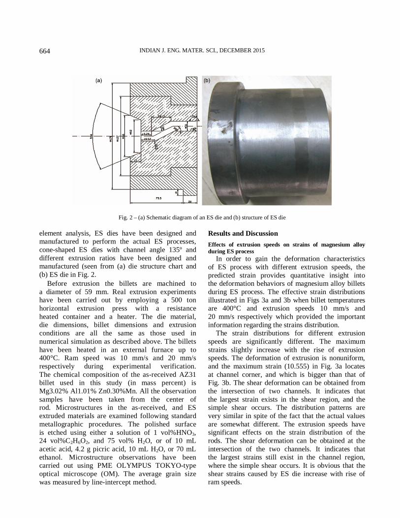
Fig. 2 – (a) Schematic diagram of an ES die and (b) structure of ES die
element analysis, ES dies have been designed and manufactured to perform the actual ES processes,
cone-shaped ES dies with channel angle 135º and
different extrusion ratios have been designed and manufactured (seen from (a) die structure chart and
(b) ES die in Fig. 2.
Before extrusion the billets are machined to
a diameter of 59 mm. Real extrusion experiments have been carried out by employing a 500 ton
horizontal extrusion press with a resistance
heated container and a heater. The die material, die dimensions, billet dimensions and extrusion
conditions are all the same as those used in
numerical simulation as described above. The billets
have been heated in an external furnace up to 400°C. Ram speed was 10 mm/s and 20 mm/s
respectively during experimental verification.
The chemical composition of the as-received AZ31 billet used in this study (in mass percent) is
Mg3.02% Al1.01% Zn0.30%Mn. All the observation
samples have been taken from the center of rod. Microstructures in the as-received, and ES
extruded materials are examined following standard
metallographic procedures. The polished surface
is etched using either a solution of 1 vol%HNO3, 24 vol%C2H6O2, and 75 vol% H2O, or of 10 mL
acetic acid, 4.2 g picric acid, 10 mL H2O, or 70 mL
ethanol. Microstructure observations have been carried out using PME OLYMPUS TOKYO-type
optical microscope (OM). The average grain size
was measured by line-intercept method.
Results and Discussion
Effects of extrusion speeds on strains of magnesium alloy
during ES process
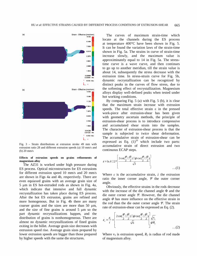
In order to gain the deformation characteristics
of ES process with different extrusion speeds, the
predicted strain provides quantitative insight into the deformation behaviors of magnesium alloy billets
during ES process. The effective strain distributions
illustrated in Figs 3a and 3b when billet temperatures are 400°C and extrusion speeds 10 mm/s and
20 mm/s respectively which provided the important
information regarding the strains distribution. The strain distributions for different extrusion
speeds are significantly different. The maximum
strains slightly increase with the rise of extrusion speeds. The deformation of extrusion is nonuniform,
and the maximum strain (10.555) in Fig. 3a locates
at channel corner, and which is bigger than that of Fig. 3b. The shear deformation can be obtained from
the intersection of two channels. It indicates that
the largest strain exists in the shear region, and the simple shear occurs. The distribution patterns are
very similar in spite of the fact that the actual values
are somewhat different. The extrusion speeds have significant effects on the strain distribution of the
rods. The shear deformation can be obtained at the
intersection of the two channels. It indicates that the largest strains still exist in the channel region,
where the simple shear occurs. It is obvious that the
shear strains caused by ES die increase with rise of ram speeds.
HU et al: EFFECTIVE STRAINS CAUSED BY DIFFERENT PROCESS CONDITIONS OF EXTRUSION-SHEAR
665
Fig. 3 – Strain distributions at extrusion stroke 49 mm with extrusion ratio 28 and different extrusion speeds (a) 10 mm/s and (b) 20 mm/s
Effects of extrusion speeds on grains refinements of
magnesium alloy
The AZ31 is worked under high pressure during
ES process. Optical microstructures for ES extrusions for different extrusion speed 10 mm/s and 20 mm/s
are shown in Figs 4a and 4b, respectively. There are
even equiaxed grains with an average grain size of 5 µm in ES hot-extruded rods as shown in Fig. 4a,
which indicate that intensive and full dynamic
recrystallization has taken place during ES process. After the hot ES extrusion, grains are refined and
more homogenous. But in Fig. 4b there are many
coarser grains and the sizes are more than 50 µm,
and the size of fine grains is around 5 µm so the part dynamic recrystallizations happen, and the
distribution of grains is nonhomogeneous. There are
almost no dynamic recrystallizations of fined grains exiting in the billet. Average grain size decreases with
extrusion speed rise. Average grain sizes prepared by
lower extrusion speeds are bigger than those prepared by higher speeds with the same die structures.
The curves of maximum strain-time which
locate at the channels during the ES process
at temperature 400°C have been shown in Fig. 5. It can be found the variation laws of the strain-time
shown in Fig. 5a. The strains in curve of strain-time
increase slowly, and the maximum value is
approximinately equal to 14 in Fig. 5a. The stress-time curve is a wave curve, and then continues
to go up to another meridian, till the strain value is
about 14, subsequently the stress decrease with the extrusion time. In stress-strain curve for Fig. 5b,
dynamic recrystallization can be recognized by
distinct peaks in the curves of flow stress, due to
the softening effect of recrystallization. Magnesium alloys display well-defined peaks when tested under
hot working conditions.
By comparing Fig. 5 (a) with Fig. 5 (b), it is clear that the maximum strain increase with extrusion
speeds. The total effective strain ε in the pressed
work-piece after extrusion-shear has been given with geometry ascertain methods, the principle of
extrusion-shear process is to introduce compressive
and accumulated shear strain into the samples. The character of extrusion-shear process is that the
sample is subjected to twice shear deformation.
The accumulative strain of extrusion-shear can be
expressed as Eq. (1)20
which include two parts: accumulative strain of direct extrusion and two
continuous ECAP steps.
2cot( ) csc( )2 2 2 2ln 2*
3
φ ψ φ ψψ
ε λ
+ + +
= + …(1)
Where ε is the accumulative strain, λ the extrusion
ratio the inner corner angle, Ψ the outer corner angle.
Obviously, the effective strains in the rods decrease
with the increase of the die channel angle Φ and the
die outer corner angle Ψ. However, the die channel angle Φ has more influence on the effective strain in
the rod than the die outer corner angle Ψ. The strain
rate of extrusion-shear can be expressed as Eq. (2).
.22
2 '
2
2cot( ) csc( )2 2 2 2
6
v
t R
φ ψ φ ψψ
εε
ψ
+ + +
= =
…(2)
Where v2 is extrusion speed, R2 is radius of rod made of magnesium alloy.

INDIAN J. ENG. MATER. SCI., DECEMBER 2015
666
Fig. 4 – Microstructures of AZ31 Mg processed by ES at the temperature 400°C with extrusion ratio 28 and different extrusion speed (a) 10 mm/s and (b) 20 mm/s
Fig. 5 – The curves of strain-time for extrusion speed (a) 10 mm/s and (b) 20 mm/s with extrusion temperature 400°C
From the Eqs (1) and (2) it is found that the strain and strain rate distributions for different ram speeds are
very significantly different, and very closely related
with the parameters of ES die structures. The response
of magnesium alloy to be extruded can be influenced by the speeds of deformation. The temperature
developed in extrusion increases with increasing
extrusion speed. Temperature rise is due to the fact that
the strain rate is directly proportional to the ram speed, and the magnitude of the generated heat is proportional
to the strain rate. But the slower the extrusion speed is
the more time will be available for the generated heat to flow. Quantity of thermal rating caused by
extrusion-shear would influence the surface quality of
extruded rod. The volume thermal rating which includes plastic deformation of work-piece as well as
the contact surface friction may be expressed as20
.
.
1p
V
Q dVV
σ ε− −
= ∫ … (3)
Where σ−
stands for the equivalent stress,
.
pε−
the equivalent plastic rate of strain, v is the unit volume.
The metal extrusion process produces the heat
mainly concentrates in first and the second deformation range.
Effects of extrusion ratios on grain refinements of magnesium
alloy
It is obvious that the shear strain caused by ES die
with extrusion ratio 28 is bigger than which caused by ES die with extrusion ratio 12 at extrusion time
5.5 s in Fig. 6. The strain distributions for different
extrusion ratios of ES die are significantly different and not even. The maximum strains slightly increase
HU et al: EFFECTIVE STRAINS CAUSED BY DIFFERENT PROCESS CONDITIONS OF EXTRUSION-SHEAR
667
with the rise of extrusion ratios. The deformation of
the initial extrusion is nonuniform, and the highest
strain (10.98) in Fig. 6a. The maximum shear deformation can be obtained at the intersection of
the two channels. Distributions of the strains are
lamellar with distinct deformation gradients in the deformation zone. The deformation of this position
is close to the simple shear deformation.
Fig. 6 – The distributions of the strains with different extrusion ratios (a) 12 and (b) 28
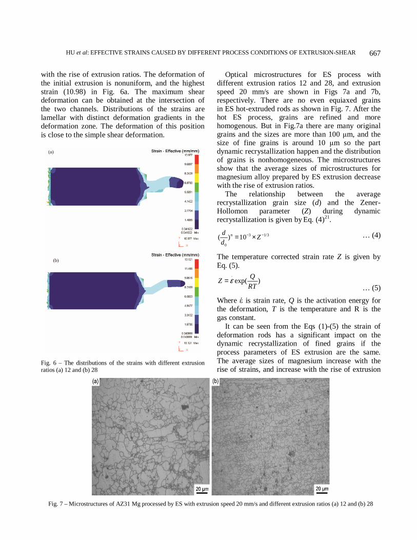
Optical microstructures for ES process with different extrusion ratios 12 and 28, and extrusion
speed 20 mm/s are shown in Figs 7a and 7b, respectively. There are no even equiaxed grains in ES hot-extruded rods as shown in Fig. 7. After the hot ES process, grains are refined and more homogenous. But in Fig.7a there are many original grains and the sizes are more than 100 µm, and the size of fine grains is around 10 µm so the part dynamic recrystallization happen and the distribution of grains is nonhomogeneous. The microstructures show that the average sizes of microstructures for magnesium alloy prepared by ES extrusion decrease with the rise of extrusion ratios.
The relationship between the average recrystallization grain size (d) and the Zener-Hollomon parameter (Z) during dynamic recrystallization is given by Eq. (4)21.
3 1/3
0
( ) 10ndZ
d
− −= × … (4)
The temperature corrected strain rate Z is given by
Eq. (5).
.
exp( )Q
ZRT
ε= … (5)
Where έ is strain rate, Q is the activation energy for the deformation, T is the temperature and R is the
gas constant.
It can be seen from the Eqs (1)-(5) the strain of
deformation rods has a significant impact on the dynamic recrystallization of fined grains if the
process parameters of ES extrusion are the same.
The average sizes of magnesium increase with the rise of strains, and increase with the rise of extrusion
Fig. 7 – Microstructures of AZ31 Mg processed by ES with extrusion speed 20 mm/s and different extrusion ratios (a) 12 and (b) 28

INDIAN J. ENG. MATER. SCI., DECEMBER 2015
668
speeds. The sizes and volume fraction of dynamic
recrystallization of fined grains are inversely
proportional to the extrusion speeds and extrusion ratios. It is obvious that average sizes of grains for
higher extrusion speeds and extrusion ratios are finer
than those prepared by ES extrusion with lower
extrusion speeds and extrusion ratios.
Conclusions
In accordance to finite element analysis and experimental results of different extrusion speeds and
extrusion ratios for ES extrusion have been
researched. 3D FEM simulation of as-cast AZ31 magnesium alloy billets subjected to ES process with
different extrusion speeds and extrusion ratios have
been carried out successfully. The strains in the
extruded rods have been predicted during ES process. ES process with different extrusion speeds and
extrusion ratios have been applied to fabricate AZ31
magnesium alloy rod with preheated temperature 400°C. The strains of ES process slightly increase
with the rise of extrusion speeds. Average grain sizes
prepared by lower extrusion speeds are bigger than
those prepared by higher speeds with the same die structures. The strains slightly decrease with
the rise of extrusion ratios. The average sizes of
microstructures for magnesium alloy prepared by ES extrusion decrease with the rise of extrusion ratios.
Acknowledgements
This work was supported by the foundation of
the post doctorate in Chongqing City and Project Number Xm201327, and China Postdoctoral Science
Foundation funded project (2015T81087 and
2014M552575), and Chongquing Natural Science
Foundation Project of cstc2014jcyjA50004 and cstc2015jcyjB0292, and Scientific and Technological
Research Program of Chongquing Municipal
Education Commission KJ1500939.
References 1 Hu Hongjun,Zhang Dingfei & Zhang JunPing, Trans
Nonferrous Met Soc China, 3 (2010) 478-483.
2 Yang X Y, Miura H & Sakai T, Trans Nonferrous Met Soc
China, 17 (2007) 1139-1142.
3 Hu Hongjun, Zhang Dingfei, Yang MingBo & Deng Ming,
Trans Nonferrous Met Soc China,21 (2011) 243-249.
4 Hu Hongjun, Zhang Dingfei & Pan Fusheng, Chin J
Nonferrous Met, 20 (2010) 259-266.
5 Jiang Hong, Fan Zhiguo & Xie Chaoying, Mater Sci Eng:
A, 485 (2007) 409-414.
6 Matsuyama K, Miyahara Y, Horita Z & Langdon T G, Acta
Mater, 51 (2003) 3073-3084
7 Matsuyama K, Miyahara Y, Horita Z & Langdon T G, Acta
Mater, 51 (2003) 3073-3084.
8 Orlov Dmitry, Raab George, Torbjorn T, Lamark, Mikhail Popov & Uri Estrin, Acta Mater, 59 (2011) 375-385.
9 Chung Y H, Park J W & Lee K H, Mater Inter, 12 (2006) 289-293.
10 Kim H S, Hong S I & Seo M H, J Mater Res, 16 (2001) 856-864.
11 Hu Hongjun, ZhaiZhiye, Wang Hao & Fan JunZhi, Mater
Res, 17 (2014) 987-995.
12 Gong X & Chou K, Proc ASME 2013 Int Manufacturing
Science and Engineering Conf, Madison, 2013, 10-14.
13 Gong X, Kang S B, Li S & Cho J H, Mater Des, 30 (2009) 3345-3350.
14 Gong X, Li H, Kang S B, Cho J H & Li S, Mater Des, 31 (2010) 1581-1587.
15 Valiev R Z, Krasilnikov N A & Taenev N K, Mater Sci Eng A, 137 (1980) 35-40.
16 Hu H, Zhang D, Yang M & Deng M, Rare Metal Mater Eng, 39 (2010) 2147-2151.
17 Bakhtiani Tushar, El-Mounayri Hazim & Zhang Jing, Mater
Today:Proc, 1 (2014) 94-106
18 García-Domínguez A, Claver J, Camacho A M & Sebastián M A, Procedia Eng, 100 (2015) 74-83
19 Mayavarama R, Sajja U, Secli C & Niranjan S, Procedia
CIRP, 12 (2013) 276-281
20 Matsubara K, Miyahara Y, Horit Z & Langdon T G,
Metall Mater Trans A, 35A (2004) 1735-1744.
21 Hu H J, Fan J Z, Zhai Z Y, Wang H, Li Y Y & Gong X B, Russ J Non-Ferr Met, 55 (2014) 254-58.