effects of biologics on pedicle screw fixation in a sheep
TRANSCRIPT

Marquette Universitye-Publications@Marquette
Master's Theses (2009 -) Dissertations, Theses, and Professional Projects
Effects of Biologics on Pedicle Screw Fixation in aSheep Model: Histological and BiomechanicalAnalysisAkshi AroraMarquette University
Recommended CitationArora, Akshi, "Effects of Biologics on Pedicle Screw Fixation in a Sheep Model: Histological and Biomechanical Analysis" (2010).Master's Theses (2009 -). Paper 64.http://epublications.marquette.edu/theses_open/64

EFFECTS OF BIOLOGICS ON PEDICLE SCREW FIXATION
IN A SHEEP MODEL: HISTOLOGICAL
AND BIOMECHANICAL
ANALYSIS
by
Akshi Arora, BDS
A Thesis submitted to the Faculty of the Graduate School,
Marquette University,
in Partial Fulfillment of the Requirements for
the Degree of Master of Science
Milwaukee, Wisconsin
August 2010

ABSTRACT
EFFECTS OF BIOLOGICS ON PEDICLE SCREW FIXATION
IN A SHEEP MODEL: HISTOLOGICAL
AND BIOMECHANICAL
ANALYSIS
Akshi Arora, BDS
Marquette University, 2010
Objective: Osteoinductive recombinant human bone morphogenetic protein
(rhBMP-2) was delivered on an absorbable collagen sponge (ACS) within a novel
titanium screw implant in an IACUC approved non-osteoporotic ovine spine model.
Biomechanical pull-out strength, undecalcified histology, microradiography, and
quantitative histomorphometry were used to assess effects of augmentation with rhBMP-
2 on the holding power and peri-implant bone formation.
Methodology: rhBMP-2 (0.43 mg/ml) soaked ACS was placed within and around
cannulated and fenestrated titanium pedicle screw implants. Sixty-four implants were
randomly divided into 4 treatment groups (n=16 each). Biomechanical pull-out testing
was done on half of the screws (n=32) to determine the pull-out strength, stiffness, and
energy to failure. For histology, half of the implants were sectioned perpendicular to the
long axis (axial), and the other half were sectioned parallel to long axis (longitudinal).
Differential staining, microradiography and histomorphometry were performed. Data
were statistically analyzed by ANOVA (p=0.05) and Bonferroni/Dunn pair-wise
comparisons (p=0.0083).
Findings: Pull-out test: Empty 6 weeks group demonstrated the highest pull-out
strength (3718N) compared to rhBMP-2/ACS 12 weeks (2330N, p<0.0025,
Bonferroni/Dunn) and 6 weeks (2074N, p<0.0024, Bonferroni/Dunn) groups. rhBMP-
2/ACS 12 weeks group showed trend of improvement in stiffness over rhBMP-2/ACS-6
weeks (p<0.016, Bonferroni/Dunn). Empty 6 weeks group showed the highest pull-out
energy. The rhBMP-2/ACS-12 weeks group showed the lowest required energy.
Histomorphometry: No significant differences were found in amount of bone formed
between the treatment groups for both axial (p=0.2359, ANOVA) and longitudinal
sections (p=0.0569, ANOVA). Bone from the lowest mineral density in 6 weeks rhBMP-
2/ACS was significantly higher than other groups. rhBMP-2 application was associated
with early transient bone resorption and extensive de novo osteopenic bone as far as 8-10
mm away from the screw.
Conclusions: rhBMP-2 did not significantly improve the biomechanical pull-out
properties (stiffness, strength, and energy) of the titanium implant. 12 weeks rhBMP-
2/ACS specimens had improved biomechanical pull-out strength and stiffness compared
to 6 weeks rhBMP-2/ACS specimens. rhBMP-2 application was associated with early
transient bone resorption, de novo florid osteopenic bone, and statistically significant
bone density differences at the 6 weeks period. These were replaced by remodeled bone
at the 12 weeks time period.

i
ACKNOWLEDGMENTS
Akshi Arora, BDS
I wish to express my gratitude to many people who have been of crucial help and
support while conducting the research for this thesis. First and foremost, I’d like to
sincerely thank my thesis director, Dr. Jeffrey M. Toth for his guidance, unending
support and encouragement while training for this project, conducting research and in
preparing this dissertation. I am grateful to him for showing his faith in this project and in
my abilities to figure things out on my own. I also thank him for the countless hours in
discussion and for his patience while explaining to me the histological findings and
answering my questions. I am highly appreciative of my Program Director and committee
member, Dr. David Berzins for his guidance, support and assistance with anything and
everything I needed throughout my graduate program. I also thank my thesis committee
member Dr. Mei Wang for her research insights in this project, supervision in
biomechanical testing, conducting the statistical analysis and her supportive comments
along the way.
I am thankful to Ms Linda McGrady for carrying out the biomechanical testing
and collecting the test results as well as for her help with the line profile data collection
and analysis. I particularly wish to acknowledge my friend and colleague Dr. Sharath
Chandra V. Chedella for his continued assistance, advice and input along each and every
step of this project.
I am indebted to the Biomaterials Research Laboratory and the Orthopedic and
Rehabilitation Engineering Center, Medical College of Wisconsin, Milwaukee, WI as

ii
well as to the Marquette University Graduate School, Milwaukee, WI for awarding me
scholarships in 2008 and 2009, thus helping me complete this project. I also thank and
acknowledge Medtronic Spinal & Biologics, Memphis, TN for their research support and
funding for this project, without which none of this work could have been completed.
I am grateful to my parents, Dr. Satish K. Arora and Veena Arora for their
unconditional love, support and encouragement and for making me the person I am
today. They have been the driving force behind all my undertakings in life and have
encouraged to me to pursue each academic endeavor to the fullest. Thank you Dad, you
have been my first role model!
My endeavor in life would never have been successful without the love and
support of my husband Deepak. I am extremely thankful to him for his patience and
understanding even when I wasn’t able to give him enough time. Thank you for your
endless willingness to listen to my successes and frustrations, for your words of advice,
and most importantly, for believing in me when I didn’t.
Special thanks to my in-laws, siblings, all my friends and families who have
supported me throughout my academic career and have influenced me in many ways.

iii
TABLE OF CONTENTS
ACKNOWLEDGMENTS....................................................................................................i
LIST OF TABLES.............................................................................................................vii
LIST OF FIGURES……………………………………………………………………..viii
CHAPTER 1. INTRODUCTION………………………………………………………...1
CHAPTER 2. LITERATURE REVIEW
2.1. Elements of the Spine………………………………………………………...5
2.2. Conditions Affecting the Spine
2.2.1. Spinal Deformities………………………………………………….6
2.2.2. Bone Metabolic Disease-Osteoporosis……………………………..6
2.2.3. Spondylolysis and Spondylolisthesis……………………………….8
2.2.4. Fractures of the Spine………………………………………………8
2.2.5. Spinal Cord Injury (SCI)…………………………………………..10
2.3. Treatment Modalities for Spinal Disorders
2.3.1. Non-Operative Treatment…………………………………………11
2.3.2. Surgical Treatment & Internal Fixation of the Spine……………..11
2.4. Internal Fixation of the Spine
2.4.1. History……………………………………………………………..12
2.4.2. Methods for Internal Fixation of the Spine………………………..14
2.4.3. Need of Spinal Fusion with Internal Fixation……………………..14
2.4.4. Approaches for Spinal Surgery……………………………………15
2.5. Spinal Pedicle Screws
2.5.1. Background and History of Pedicle Screws……………………….16
iv
2.5.2. Why Pedicle?...................................................................................17
2.5.3. Principles of Design of a Pedicle screw…………………………...17
2.5.4. Advantages with the Use of Pedicle Screws………………………18
2.5.5. Indications of Pedicle Screw Fixation…………………………….19
2.5.6. Complications Associated with the Use of Pedicle Screws and
Related Studies…………………………………………………………...20
2.5.7. Methods Designed to Improve Fixation of Pedicle Screw………..22
2.6. Osteoinductive Materials and Bone Morphogenetic Proteins (BMPs)
2.6.1. History of BMPs…………………………………………………..27
2.6.2. Classification and Structure of BMP Molecule…………………...28
2.6.3. Role of BMPs in Bone Formation………………………………...29
2.7. Recombinant Human Bone Morphogenetic Protein (rhBMP-2)
2.7.1. Mechanism of Action: Physical and Chemical (Molecular) Basis..30
2.7.2. Carriers of rhBMP-2 and Role of Carrier in Different Types of Bone
Deposition………………………………………………………………..32
2.7.3. Preclinical and Clinical Spine Studies with rhBMP-2…………….34
2.7.4. Factors Playing a Role in Action of rhBMP-2…………………….36
2.7.5. Complications with the Use of rhBMP-2………………………….37
2.7.6. Indications of rhBMP-2 Approved by FDA………………………38
2.8. Sheep as a Model for Human Spine Study
2.8.1. Need for an Animal Model………………………………………..39
2.8.2. Why Sheep?.....................................................................................39
CHAPTER 3. MATERIALS AND METHODS
3.1. Pedicle Screws………………………………………………………………42

v
3.2. Recombinant Human Bone Morphogenetic Protein-2 (rhBMP-2)………….44
3.3. Animal Model……………………………………………………………….44
3.4. Methods of Analysis
3.4.1. Biomechanical Assessment………………………………………..48
3.4.2. Undecalcified Histology…………………………………………..52
3.4.3. Microradiography…………………………………………………57
3.4.4. Histomorphometry………………………………………………...60
CHAPTER 4. RESULTS
4.1. Biomechanical Assessment………………………………………………….71
4.1.1. Pull-out Strength…………………………………………………..74
4.1.2. Pull-out Stiffness…………………………………………………..76
4.1.3. Energy Absorbed to the Point of Failure………………………….79
4.2. Histomorphometry
4.2.1. Quantitative Analysis (Percentage Bone in the Region of Interest)81
4.2.2. Qualitative analysis (Bone Density Variations in the Region of
Interest)…………………………………………………………………..89
4.2.3. Line Profile Analysis (Trabecular Thickness in the Region of
Interest)…………………………………………………………………..98
4.2.4. Correlation Between the Biomechanical Variables and Different
Bone Density Ranges…………………………………………………...100
4.3. Undecalcified Histology
4.3.1. Axial Sections……………………………………………………103
4.3.2. Longitudinal Sections……………………………………………115
CHAPTER 5. DISCUSSION…………………………………………………………...127

vi
BIBLIOGRAPHY………………………………………………………………………136
APPENDIX A…………………………………………………………………………..152
APPENDIX B…………………………………………………………………………..155
APPENDIX C…………………………………………………………………………..156

vii
LIST OF TABLES
Table 3-1. Treatment groups and time periods used for the study
Table 3-2. Animal number and time point for harvesting of each vertebral level
Table 4-1. Failure type of the eight screws
Table 4-2. List of outliers
Table 4-3. Individual screw pull-out strength (in Newtons). The outliers are highlighted
in yellow
Table 4-4. Individual screw pull-out stiffness (in N/mm). The outliers are highlighted in
yellow
Table 4-5. Individual screw pull-out energy data (in N-m). The outliers are highlighted in
yellow
Table 4-6. Individual data and mean (±SD) of percentage bone formation in the circular
region of interest for the axial specimens among the four treatment groups
Table 4-7. Individual data and mean (±SD) percentage bone formation in the rectangular
region of interest for the longitudinal specimens among the four treatment groups
Table 4-8. The mean (±SD) percentage bone in each of the four density divisions in the
circular region of interest for the axial specimens
Table 4-9. The mean (±SD) percentage bone in each of the four density divisions in the
circular region of interest for the longitudinal specimens
Table 4-10. The mean (±SD) trabecular thickness (µm) for each treatment group

viii
LIST OF FIGURES
Figure 3-1. Pedicle screw design used in the study
Figure 3-2. A closer view of the pedicle screw showing the cannula running in the center
of the screw
Figure 3-3. A closer view of the pedicle screw showing the region of fenestrations
Figure 3-4. Servo hydraulic material testing machine for biomechanical pull-out test of
the pedicle screw A) Final assembly; B) Individual components of the apparatus
Figure 3-5. Grossed specimen of the left side of the vertebral body with the pedicle screw
and its label
Figure 3-6. Processed specimen of the vertebral body and pedicle screw embedded in
methyl methacrylate and labeled
Figure 3-7. Diamond coated wafering blade used for sectioning of the vertebral body
specimens
Figure 3-8 A. Alignment of pedicle screw for axial sections- perpendicular to the
direction of sectioning
Figure 3-8 B. Alignment of pedicle screw for longitudinal sections- parallel to the
direction of sectioning
Figure 3-9. Digital images of radiographs of A) Axial section of animal R156 L4 LT cut
10; B) Longitudinal section of animal R161 L4 RT cut 4. Figure A shows the
radiographic differentiation between the bone and pedicle screw. The
fenestrations and cannula can be seen in Figure B
Figure 3-10. Digital images of the regions of interest A) Axial section showing a circle of
diameter 7.5 mm; B) Longitudinal section showing a rectangular box of length 14 mm
and width 7.5 mm
Figure 3-11. Screen captures of selected gray scale range of bone and a histogram for the
gray scale range in the region of interest for A) Axial section of animal R156 L4 LT cut
13; B) Longitudinal section of animal R156 L5 RT cut 3
Figure 3-12. Screen captures of density variations for the selected gray scale range of
bone in the region of interest for A) Axial section of animal R156 L4 LT cut 13; B)
Longitudinal section of animal R156 L5 RT cut 3
7.5 mm

ix
Figure 3-13 A) Digital image showing a black and white mask for longitudinal section of
animal R156 L5 RT cut 3. The same gray scale range used for histomorphometry, was
used for preparing the mask
Figure 3-13 B) Digital image of a longitudinal section of animal R156 L5 RT cut 3 with a
10 mm long superior line and plateau and valley like line profile graph. The plateaus
represent bony trabeculae C) Table with line profile data for the superior line
Figure 3-13 D) Digital image showing 10 mm long inferior line and line profile graph for
longitudinal section of animal R156 L5 RT cut 3. Plateaus represent bony trabeculae; E)
Table showing line profile data for the inferior line
Figure 4-1 A. Axial view (with anatomical right on the right side of the image) of the four
vertebral bodies of animal R157 (rhBMP-2/ACS 6 weeks). The screws used for pull-out
test were L2 right (top left), L3 left (top right), L4 left (bottom left), and L5 right
(bottom right). Pointer showing radiolucency in association with the screw
Figure 4-1 B. Axial view (with anatomical right on the right side of the image) of the two
vertebral bodies of animal R165 L5 RT (ACS alone 12 weeks) and R165 L3 RT (rhBMP
-2/ACS 12 weeks). Pointer showing radiolucency associated with the screw
Figure 4-2. Load displacement curve generated using software from the biomechanical
pull-out data of animal R163 L4 RT
Figure 4-3. The mean (±SD) pull-out strength of the pedicle screws among the four
treatment groups
Figure 4-4. The mean (±SD) pull-out stiffness of the pedicle screws among the four
treatment groups
Figure 4-5. The mean (±SD) energy absorbed up to point of failure among the four
treatment groups
Figure 4-6 A. Quantitative histomorphometry (AXIAL) screen capture for the Empty 6
weeks animal R162 L5 LT cut 15
Figure 4-6 B. Quantitative histomorphometry (AXIAL) screen capture for the rhBMP-
2/ACS 6 weeks animal R156 L4 LT cut 13
Figure 4-6 C. Quantitative histomorphometry (AXIAL) screen capture for the ACS alone
12 weeks animal R155 L2 RT cut 8
Figure 4-6 D. Quantitative histomorphometry (AXIAL) screen capture for the rhBMP-
2/ACS 12 weeks animal R163 L2 RT cut 5
x
Figure 4-7. The mean (±SD) percentage bone formation in the circular region of interest
for the axial specimens among the four treatment groups
Figure 4-8 A. Quantitative histomorphometry (LONGITUDINAL) screen capture for the
Empty 6 weeks animal R161 L4 RT cut 5
Figure 4-8 B. Quantitative histomorphometry (LONGITUDINAL) screen capture for the
rhBMP-2/ACS 6 weeks animal R156 L5 RT cut 5
Figure 4-8 C. Quantitative histomorphometry (LONGITUDINAL) screen capture for the
ACS alone 12 weeks animal R155 L3 RT cut 4
Figure 4-8 D. Quantitative histomorphometry (LONGITUDINAL) screen capture for the
rhBMP-2/ACS 12 weeks animal R155 L4 LT cut 5
Figure 4-9. The mean (±SD) percentage bone formation in the rectangular region of
interest for the longitudinal specimens among the four treatment groups
Figure 4-10. The graphical representation of the mean (±SD) percentage bone in each of
the four density divisions in the circular region of interest for the axial specimens
Figure 4-11 A. Screen capture (AXIAL) showing percentage bone in the four density
divisions for the Empty 6 weeks animal R162 L5 LT cut 15
Figure 4-11 B. Screen capture (AXIAL) showing the four bone density divisions for the
rhBMP-2/ ACS 6 weeks animal R156 L4 LT cut 13. Pointer indicates to a significantly
greater amount of bone corresponding to Division 1 (lowest density) bone in the
rhBMP-2/ACS 6 weeks group
Figure 4-11 C. Screen capture (AXIAL) showing percentage bone in the four density
divisions for the ACS alone 12 weeks animal R155 L2 RT cut 8
Figure 4-11 D. Screen capture (AXIAL) showing percentage bone in the four density
divisions for the ACS alone 12 weeks animal R163 L2 RT cut 5
Figure 4-12. The mean (±SD) percentage bone for each density division in the
rectangular region of interest for the longitudinal specimens among the four
treatment groups
Figure 4-13 A. Screen capture (LONGITUDINAL) showing percentage bone in the four
density divisions the Empty 6 weeks animal R161 L4 RT cut 5
Figure 4-13 B. Screen capture (LONGITUDINAL) showing percentage bone in the four
density divisions for the rhBMP-2/ACS 6 weeks animal R156 L5 RT cut 5
xi
Figure 4-13 C. Screen capture (LONGITUDINAL) showing percentage bone in the four
density divisions for the ACS alone 12 weeks animal R155 L3 RT cut 4
Figure 4-13 D. Screen capture (LONGITUDINAL) showing percentage bone in the four
density divisions for the rhBMP-2/ACS 12 weeks animal R155 L4 LT cut 5
Figure 4-14. Graph showing mean trabecular thickness (±SD) for the treatment groups
Figure 4-15 A, B. A negative correlation between the stiffness and strength of axial
pedicle screws and the percent area of Division 1 weak bone
Figure 4-15 C, D. A positive correlation between the stiffness and strength of axial
pedicle screws and the percent area of Division 3 strong bone
Figure 4-16 A. A stained section and corresponding microradiograph of animal R162 L5
LT cut 12 (EMPTY 6 weeks) showing good bone contact on the peri-implant interface
(pointer) and bone formation within the cannula and fenestration (star).
Microradiograph showing isodense bone formation within and
around the implant
Figure 4-16 B. A stained section and corresponding microradiograph of animal R156 L2
RT cut 4 (EMPTY 6 weeks) showing coarsening of trabeculae bone in the peri-implant
interface (pointer)
Figure 4-17 A. A stained section and corresponding microradiograph of animal R156 L4
LT cut 10 (rhBMP-2/ACS 6 weeks) showing poor bone contact on the peri-implant
interface (yellow pointer) and extensive remodeled bone within the cannula and
fenestration (star). Microradiograph showing that the remodeled bone was
osteopenic and hypodense bone and extended as much as 8 mm from the
screw (red pointer)
Figure 4-17 B. A stained section of animal R161 L2 LT cut 9 (rhBMP-2/ACS 6 weeks)
showing poor peri-implant bone contact (yellow pointer) and good amount of
remodeled bone within the cannula and fenestration (star). Microradiograph
showing slightly hypodense remodeled bone in the cannula, fenestration
and exostosis (green pointer)
Figure 4-17 C. A stained section and microradiograph of animal R157 L2 LT cut 9
(rhBMP-2/ACS 6 weeks) showing poor bone contact on the peri-implant interface
(yellow pointer) and absence of bone within the cannula and fenestration (star).
Hematoma can be seen distal to the screw (red pointer). Microradiograph
showing osteopenic hypodense remodeled bone around the implant and
hematoma (green pointer)
xii
Figure 4-17 D. A more dorsal stained section of animal R157 L2 LT cut 14 (rhBMP-
2/ACS 6 weeks) showing a well defined fibrous capsule around the screw (yellow
pointer). Microradiograph showing bony fragments within the cannula (red
pointer)
Figure 4-17 E. A stained section and microradiograph of animal R157 L4 RT cut 4
(rhBMP-2/ACS 6 weeks) showing poor bone contact with the implant (yellow
pointer) and absence of bone within the cannula (star). Seroma is seen ventral
and caudal to the screw (red pointer). Microradiograph showing osteopenic
and hypodense remodeled bone near the cyst and on the cranial aspect of
the screw (green pointer)
Figure 4-17 F. A more dorsal stained section of animal R157 L4 RT cut 13 (rhBMP-
2/ACS 6 weeks) showing well defined fibrous capsule around the screw (yellow
pointer). Microradiograph showing bony fragments within the cannula (red
pointer)
Figure 4-18 A. A ventral stained section and microradiograph of animal R160 L3 RT cut
10 (ACS alone 12 weeks) with exclusive bone contact on the peri-implant interface
(yellow pointer) and good amount of within the cannula and fenestration (star).
Microradiograph showing coarse and isodense trabeculae around the screw
(red pointer)
Figure 4-18 B. A more dorsal stained section and microradiograph of animal R160 L3 RT
cut 14 (ACS alone 12 weeks) showing intervening fibrous connective tissue on the peri-
implant interface (yellow pointer) and sparse bony trabeculae within the cannula and
fenestration (star)
Figure 4-18 C. A stained section and microradiograph of animal R165 L4 LT axial cut 10
(ACS alone 12 weeks) showing a capsule of dense fibrous connective tissue on the peri-
implant interface (yellow pointer) and unincorporated bony fragments (red pointer)
Figure 4-19 A. A stained section of animal R155 L5 RT cut 3 (rhBMP-2/ACS 12 weeks)
showing intervening fibrous tissue of variable thickness on the peri-implant interface
(yellow pointer) and thick trabeculae in the cannula and fenestration (star).
Microradiograph showing isodense bony trabeculae around the screw
(red pointer)
Figure 4-19 B. A stained of animal R163 L2 RT cut 12 (rhBMP-2/ACS 12 weeks)
showing fibrous tissue on the peri-implant interface (yellow pointer).
Microradiograph showing slightly hypodense but osteopenic bony
trabeculae arranged circumferentially in a radius of 8-10 mm
(red pointer) and in the cannula and fenestration (star)

xiii
Figure 4-19 C. A stained section and microradiograph of animal R163 L5 LT cut 9
(rhBMP-2/ACS 12 weeks) showing poor bone contact on the peri-implant interface
and presence of radiolucencies in dorsal sections (yellow pointer).
Microradiograph showing slightly hypodense but osteopenic
bony trabeculae arranged circumferentially in a radius of 5-7
mm (red pointer) and in the cannula and fenestration (star)
Figure 4-19 D. A stained section of animal R165 L3 LT cut 13 (rhBMP-2/ACS 12 weeks)
showing a capsule of dense fibrous connective tissue on the peri-implant interface
(yellow pointer). Microradiograph showing radiolucency with unincorporated
bony fragments (red pointer) and isodense bone 2 mm away from the screw
(green pointer)
Figure 4-20 A. A stained section of animal R161 L4 RT cut 4 (EMPTY 6 weeks)
showing good bone contact on the peri-implant interface ventrally (yellow
pointer) and intervening fibrous tissue dorsally (green pointer) and decent
bone formation within the cannula and fenestration (star). Microradiograph
showing isodense bone within the cannula, fenestrations peri-implant
area (red pointer and star)
Figure 4-20 B. A stained section of animal R162 L2 RT cut 4 (EMPTY 6 weeks)
showing good bone contact on the peri-implant interface both ventrally and
dorsally (yellow pointer) and decent bone formation within the cannula
and fenestration (star). Microradiograph showing screw extruding
the ventral cortex bony exostosis (red pointer)
Figure 4-21 A. A stained section of animal R156 L5 RT cut 4 (rhBMP-2/ACS 6 weeks)
absence of bone contact on the peri-implant interface both ventrally and dorsally
(yellow pointer) and bone within the cannula and fenestration (star).
Microradiograph showing hypodense and osteopenic remodeled
bone 3-10 mm from the screw (red pointer) and the screw
penetrating the ventral cortex bony exostosis (green
pointer)
Figure 4-21 B. A stained section of animal R157 L3 RT cut 4 (rhBMP-2/ACS 6 weeks)
thick fibrous tissue on the peri-implant interface both ventrally and dorsally (yellow
pointer) and blood filled cyst (red pointer). Microradiograph showing areas
of hypodense and osteopenic remodeled bone within and adjacent to the
cyst (star)
Figure 4-21 C. A stained section and microradiograph of animal R157 L5 LT cut 6
(rhBMP-2/ACS 6 weeks) showing a large radiolucent void of 15 mm diameter
centered on the fenestrated aspect of the screw (yellow pointer). Areas of
remodeling can be seen on the microradiograph (red pointer)

xiv
Figure 4-22 A. A stained section of animal R160 L2 RT cut 3 (ACS alone 12 weeks)
showing excellent peri-implant bone contact ventrally and intervening fibrous tissue
dorsally (yellow pointer). Excellent bone contact in fenestration and good contact is
seen in the cannula (red pointer). Microradiograph showing areas of isodense
bone in cannula and fenestration (star) and extruded ventral tip of the screw
(green pointer)
Figure 4-22 B. A stained section with broken screw of animal R160 L3 LT cut 2 (ACS
alone 12 weeks) showing excellent peri-implant bone contact ventrally and in the
fenestration (yellow and red pointer). Microradiograph showing coarsening of
bony trabeculae bone around the implant (green pointer) and in the
fenestration (star)
Figure 4-22 C. A stained section and microradiograph of animal R165 L5 LT cut 4 (ACS
alone 12 weeks) with a thick fibrous tissue on the peri-implant interface both ventrally
and dorsally (yellow pointer) and a well defined radiolucent zone around the implant
(red pointer). Unincorporated bony fragments (star) are also visible in the
cannula and peri-implant area
Figure 4-23 A. A stained section and microradiograph of animal R155 L4 RT cut 5
(rhBMP-2/ACS 12 weeks) showing lack of bone contact and intervening fibrous
tissue on the peri-implant interface both ventrally and dorsally (yellow pointer)
and blood filled cyst (red pointer). Good amount of isodense dense bone can
be seen in the cannulated and fenestrated aspect of the screws (yellow
and red stars)
Figure 4-23 B. A stained section and microradiograph of animal R155 L4 RT cut 5
(rhBMP-2/ACS 12 weeks) showing a 1.5 mm diameter blood-filled cyst ventral
and left lateral to the tip of the pedicle screw (yellow pointer)
Figure 4-23 C. A stained section and microradiograph of animal R163 L4 LT cut 4
(rhBMP-2/ACS 12 weeks) showing lack of bone contact and intervening fibrous
tissue on the peri-implant interface both ventrally and dorsally (yellow pointer).
Three small cysts can be seen (red pointer) within a large 10-12 mm
radiolucent void, with blood on the periphery (red star). Minute
amount of bone can be seen in the cannulated and fenestrated
aspect of the screws (green stars). Microradiograph shows
hypodense bone on the outer aspect of the radiolucent
void (yellow stars)
Figure 4-23 D. A stained section and microradiograph of animal R165 L2 RT cut 5
(rhBMP-2/ACS 12 weeks) showing a thick band of fibrous tissue (>1 mm) on the
peri-implant interface both ventrally and dorsally and a well defined radiolucent
zone around the implant (yellow pointers). Unincorporated bony fragments (red
pointers) are also visible in the cannula and in the peri-implant area

1
1. INTRODUCTION:
The human spine is a complex interconnected array of vertebral bodies which not
only forms the central anatomical support system of the body but also protects the spinal
cord. The spine is susceptible to injury and wear over time. Of all the musculoskeletal
impairments reported in the United States each year, more than half (51.7% or 15.4
million) consist of impairments of the spine [1]. The most common causes of traumatic
injury to the spine include high energy fall and vehicular accidents. Due to higher
mobility and the role of the lumbar spine as the foundation of the upper body, the
incidence of injury is higher in this region [2]. Non traumatic conditions affecting the
spine include congenital and developmental anomalies, fractures secondary to
osteoporosis, degenerative disease of old age, infection, tumors and neuromuscular
disorders. Approximately 15-20 % of the adult population in the United States (~31
million people) experience low back pain. This results in an estimated 360,000 spinal
disorder correction procedures annually [1].
Spinal injury causes symptoms due to nerve impingement and pain caused by
vertebral instability. The management trend often includes rigid internal fixation of the
spine to provide initial stability, which allows for early mobilization and rehabilitation of
the patient. This is achieved by various internal fixation devices including screws, rods,
hooks and wires. Most spinal instrumentation is accompanied by the fusion of the spine,
also called as spinal arthrodesis. The rationale behind spinal arthrodesis is inhibiting the
mobility of vertebrae by creating a mechanical connection between the adjacent vertebrae
through bone growth. This alleviates painful symptoms of lumbosacral instability and

2
provides long term stability to the spine. It is estimated that more than 200,000 spine
fusion procedures are performed each year in the United States [3].
With the evolution of spinal fixation systems over the years, one of the most
widely used methods for spinal instrumentation is the transpedicular screw fixation. It
offers rigid segmental fixation and is useful for various disorders of the spine. Typically,
pedicle screws are placed through the pedicle into the body of vertebrae and then
connected with rods to stabilize the segment between the two adjacent vertebrae to
eventually fuse them. After their reclassification by the Food and Drug Administration
(FDA), pedicle screws have been extensively used in lower lumbar spine surgeries and
have dramatically improved the outcomes of spinal reconstruction surgeries. The success
of the pedicle screw construct depends on its ability to hold tightly to the adjacent bone.
Therefore, insufficient mechanical stability at the bone-screw interface can lead to
subsequent loosening and failure of the fixation. Screw loosening is significantly higher
in elderly patients and patients with osteoporosis due to low bone mineral density (BMD)
and weakened bone around the screw [4, 5].
Different methods of improving the holding properties of the screws have been
investigated and include modifications of the design of the thread, the shape and the
surface of the screws and innovative fixation augmentation techniques. Some of the
augmentation techniques that have been investigated include use of cements such as
polymethyl methacrylate (PMMA), calcium sulfate and calcium phosphate cement (CPC)
[6-10] as well as bone conductive materials such as hydroxyapatite (HA) [11-13].
Recently, the use of osteoinductive ―growth factors‖ like bone morphogenetic
proteins (BMPs), which are critical to the bone formation and healing process, have

3
revolutionized the outcome of spinal surgeries. Osteoinduction is defined as the ability of
a protein or gene to mediate the induction of bone formation singularly in a non-bony
location [14]. With the use of recombinant gene technology, recombinant forms of the
human BMPs have been engineered. These include osteoinductive recombinant human
bone morphogenetic protein-2 (rhBMP-2) and recombinant human bone morphogenetic
protein-7 (rhBMP-7), also called recombinant human osteogenic protein-1 (rhOP-1).
Although rhBMP-2 has been used with success for various procedures in preclinical and
clinical trials, the Food and Drug Administration (FDA) approval of rhBMP-2 for spinal
surgeries is with several lumbar interbody fusion constructs [15]. Numerous preclinical
and clinical studies for the posterolateral and interbody fusions have shown the ability of
rhBMP-2 to consistently produce higher fusion rates with better bone quality compared to
the control groups [16-21].
OBJECTIVES:
The current thesis is an experimental nonclinical study evaluating the effect of
incorporation of rhBMP-2 with a novel design of a pedicle screw. Lumbar pedicle screws
made of commercially pure titanium (cpTi), incorporating a cannula and fenestrations
have been introduced in this study. The lumbar spine of skeletally mature non-
osteoporotic adult sheep has been used as the model for this thesis.
The objective of the current thesis was to incorporate osteoinductive rhBMP-2,
loaded onto the Absorbable Collagen Sponge (ACS) carrier matrix (0.43 mg/ml), in
cannulated/fenestrated pedicle screws in an ovine lumbar spine model. The study was
designed to determine 1) the pull-out force, stiffness and energy absorbed to the point of

4
failure of the screw and bone interface, and 2) quality and quantity of bone formation
within and adjacent to cannulated/fenestrated pedicle screws. The four treatment groups
that were studied included: empty screw; ACS alone; rhBMP-2/ACS 6 weeks; and
rhBMP-2/ACS 12 weeks. Two groups: empty screw and ACS alone were the control
groups. Two post-operative time periods of 6 and 12 weeks were used to determine the
properties of bone formed at different stages of bone healing with rhBMP-2. The goals
were accomplished through high- resolution radiography, non-destructive biomechanical
pull-out testing and undecalcified histology with corresponding microradiography as well
as quantitative histomorphometry. The results were compared with the control screws
without osteoinductive material.
HYPOTHESIS:
The following statements were the hypotheses for this thesis. The use of rhBMP-2
and ACS treatment would act as a scaffold for the new bone growth. Experimental
treatment groups with rhBMP-2/ACS would yield superior results compared to control
groups in terms of 1) increase in the biomechanical pull-out force, stiffness and energy
absorbed to the point of failure of the screw-bone interface; and 2) augmentation in the
quality and quantity of bone formation within and adjacent to the pedicle screw. rhBMP-
2/ACS treatment group tested at 12 weeks post operatively would yield improved
biomechanical parameters as well as bone quality and quantity in comparison with the 6
weeks rhBMP-2/ACS treatment group.

5
2. LITERATURE REVIEW:
2.1. ELEMENTS OF THE SPINE:
The spine forms the central anatomical support system of the body in vertebrates.
The adult human spine consists of twenty-four separate vertebrae along with sacral and
coccygeal fused vertebrae [2,22,23]. The typical vertebra consists of a vertebral body, a
posterior arch formed by spinous and transverse processes in the posterior/ dorsal part
of the vertebra and the two pedicles connecting the vertebral body and the posterior arch.
The size of the vertebral body increases craniocaudally to accommodate higher
compressive loads experienced caudally [2,22,23]. Together, the vertebral body and the
neural arch form the spinal canal, which houses the spinal cord. Pedicles from adjacent
vertebrae form superior and inferior margins of the intervertebral foramen. These
foramina allow spinal nerves to exit and for blood vessels to enter the spinal canal
[2,22,23].
Two types of joints are formed between the adjacent vertebrae [2,22,23]. Facet
joints are located bilaterally and are composed of inferior articular facets of the superior
vertebra and superior articular facet of the inferior vertebra. Primarily, these joints direct
motion of different regions of the spine according to their orientation. They also play a
role in load sharing along with the intervertebral discs [2,23]. The intervertebral joint is
occupied by the fibro-cartilaginous intervertebral disc which serves as the spine's primary
shock absorbing system. The discs also allow for some vertebral motion.
The functions of the vertebral column include flexibility and mobility of the body;
protection of the spinal cord and internal organs; base for attachment of muscles, tendons

6
and ligaments; structural support to the head, shoulder and chest; distribution and weight
balance [24].
2.2. CONDITIONS AFFECTING THE SPINE:
A variety of disorders affect the spine. In addition, the spine is susceptible to wear
and injury over time. These disorders can incapacitate multiple functions of the body.
Some of the conditions affecting the spine include:
2.2.1. Spinal deformities:
Spinal deformities include conditions in which the spine is abnormally curved or
malaligned. One of the more frequent spinal deformities is scoliosis. It is a three-
dimensional deformity and is characterized by side to side abnormal curvature of the
spine. Scoliosis may be seen at birth (congenital scoliosis) as a result of anomalous
vertebral development in the embryo, or develop during childhood or adulthood. The
most common form of scoliosis is idiopathic scoliosis in which the cause of curvature is
unknown. About 80-85% cases of scoliosis are idiopathic [25]. Other causes of scoliosis
include- neuromuscular disorders, trauma, tumor or a reactive condition to disc herniation
[26]. In older adults, scoliosis is commonly caused secondary to degenerative disc or
joint disease [26]. The other common spinal deformity is kyphosis, which is
characterized by exaggerated outward curvature of the spine resulting in abnormal
rounding of the back. This may occur by itself and present at birth (congenital kyphosis)
or in conjugation with conditions like osteoporosis and spondylolisthesis.
2.2.2. Bone metabolic disease-Osteoporosis:

7
Natural bone remodeling is a balance between bone formation and resorption. In
certain diseases, this balance gets disrupted leading to an excessive bone formation
(osteopetrosis) or bone resorption (osteoporosis). Redan et al has defined osteoporosis as
―A reduction in bone mass and deterioration in bone micro-architecture resulting in
increased bone fragility and fracture risk‖ [27]. It usually begins in the fourth decade in
both men and women and bone loss proceeds at a rate of 3-5% per decade [28].
Trabecular thinning contributes to bone loss with age in both sexes, but trabecular loss
occurs to a greater extent in women. Osteoporotic bone becomes highly fragile, which
predisposes it to eventual fracture even with relatively minor trauma. Most common
fractures occur in the spine, and the incidence increases significantly in the seventh and
eighth decades in males and females, respectively [27]. Risk factors of osteoporotic
fractures include: postmenopausal age, white race, and low bone density prior to
menopause [29]. Women can lose spinal bone at a rate of 2-4% per year immediately
after menopause [27]. This is related to estrogen deficiency that follows menopause and
substantially increases the osteoclast number and osteoclastic bone resorption, most
likely via elevated levels of cytokines (interleukins, tumor necrosis factor-alpha [TNF-α],
etc.) [27]. Accelerated bone loss may also be associated with hyperparathyroidism,
hyperthyroidism, and corticosteroid treatment [27]. Fractures related to osteoporosis are
silently progressive and only 23% to 33% become clinically evident [28]. They are often
diagnosed when an elderly patient presents with symptoms of progressive scoliosis or
mechanical lower back pain [30]. The consequences of these fractures include pain,
progressive vertebral collapse with resultant spinal kyphosis, and systemic manifestations
[31]. It has been estimated that approximately 700,000 osteoporotic vertebral body

8
compression fractures occur each year, of which more than one-third become chronically
painful [32]. The National Osteoporosis Foundation (NOF) has estimated that more than
100 million people worldwide are at a risk for the development of fragility fractures
secondary to osteoporosis [31].
2.2.3. Spondylolysis and Spondylolisthesis:
“Spondylolysis refers to dissolution, disintegration or a defect in the pars
interarticularis of the vertebra. Spondylolisthesis is defined as the slipping or olisthesis
of a vertebra relative to an adjacent vertebra‖ [33]. It has been classified into five types
depending on the etiology: dysplastic, isthmic, traumatic, degenerative, and pathologic
conditions [34]. Isthmic spondylolisthesis is associated with fibrous defects in pars
interarticularis [35]. Degenerative spondylolisthesis is secondary to osteoarthritis and
degenerative disc disease (DDD) of old age and leads to facet incompetence and disc
degeneration. Pathologic spondylolisthesis is due to a tumor or infection of bone
affecting the pars interarticularis or the facet joints [33]. The dysplastic and isthmic
patterns are usually classified as congenital, whereas the degenerative, traumatic, and
pathologic patterns are considered as acquired [36].
2.2.4. Fractures of the spine:
Dislocation and fracture of the vertebrae may be a result of trauma or due to non-
traumatic pathological conditions. Pathological conditions that lead to weakening on
bone and cause vertebral fractures include osteoporosis, infections, tumor, etc.
Traumatic fractures:

9
Although spine fractures represent only a minority of trauma cases, their influence
on the social and financial environment of the patient is much more in comparison to
other injuries. In a recent retrospective analysis of traumatic spinal fractures in 562
patients, Leucht et al [37] revealed that the most common cause of traumatic spinal
fractures was a high-energy fall (39%), followed by traffic accidents (26.5%) [37]. They
also reported that a higher incidence of fractures of the cervicothoracic junction was
predominantly related to traffic and sport activity-related accidents, whereas the
thoracolumbar junction experienced injuries mainly due to falls. According to White &
Panjabi, this difference is related to the variation in biomechanical environment between
both regions [38]. Firstly, because of a well defined muscular apparatus in the
thoracolumbar junction, it is structurally more protected against the distraction forces.
However, compression fractures are more prevalent in this region due to greater weight
acting on individual vertebral bodies [37]. Secondly, this junction exhibits significant
alterations in flexion-extension and rotational degrees of freedom, as well as
morphological and biomechanical changes in intervertebral disc architecture [39].
In terms of anatomical location of fractures, most cases in the above study were in
the lumbar spine (50.4%), followed by the thoracic (28.8%) and cervical region (20.8%)
[37]. Previous studies have also reported majority of thoracic and lumbar injuries
occuring within the region between T11 and L1 [39,40]. The higher mobility and relative
weakness of thoracolumbar region against compression forces is probably responsible for
a greater number of fractures in the lumbar spine [29,37]. However, fractures of L4 and
L5 are rare because in comparison to the thoracolumbar junction, the lower lumbar spine
is protected by the pelvis and the stronger ligamentous and muscular attachment [41].

10
Classification of fractures of the spine:
In 1983, Denis [42] developed a three-column theory of spinal instability. Based
upon this theory, the thoracolumbar injuries have been classified into the following four
categories [29,39,42]-
Vertebral compression fractures (VCF) result from compression on the anterior
column and appears as a wedge-shaped collapse of the vertebra. These are most
commonly seen in patients of osteoporosis [28,29,43]. Burst fracture is a more severe
form and involves failure of both the anterior and middle columns resulting from axial
compression mechanism. Both columns are compressed, and the result in loss of height
of the vertebral body. Flexion-Distraction (Seat Belt or Chance Type) Injuries involve
failure of the posterior column associated with injury to ligamentous components, bony
components, or both [29]. The mechanism of injury is a flexion-distraction mechanism.
Rotational fracture-dislocation results from a combination of lateral flexion and
rotation with or without a component of posterior-anterior force. The resultant injury
pattern is failure of both posterior and middle columns with varying degrees of anterior
column insult [29]. These fractures are highly unstable and tend to be very debilitating.
2.2.5. SPINAL CORD INJURY (SCI):
Spinal fractures and dislocations can pinch, compress, and even tear the spinal
cord and result in spinal cord injury (SCI). Neurologic deficit reportedly occurs in
approximately 15% to 20% of thoracolumbar fractures and dislocations; this is an injury
combination that affects about 1 in every 20,000 people in the United States [42,44].
According to an annual report by the National Spinal Cord Injury Statistical Center

11
Alabama in 2009, it is estimated that the annual incidence of spinal cord injury (SCI) in
the US, excluding those who die at the scene of the accident is approximately 12,000 new
cases each year or approximately 30-40 cases per million [45]. Since 2005, vehicular
accidents account for the maximum SCI, with about 42.1% reported cases of SCI [45].
2.3. TREATMENT MODALITIES FOR SPINAL DISORDERS:
The goals of treatment for spinal injuries and disorders are directed towards
restoration of a painless physiologic status, as well as the dynamic and protective
function of the spine. This requires a stable healing of the affected spine. The selection of
treatment modality for spinal trauma and pathology varies with the severity and location
of injury or pathology, and whether there is involvement of spinal cord or spinal nerves.
2.3.1. Non-operative treatment:
A number of common injuries do not require reduction and may be effectively
treated by providing pain relief with analgesics, a minimal period of immobilization, and
prompt restoration of function. Others require non-operative management including
reduction by traction and manipulation of the fracture followed by immobilization of the
reduced fracture using casts, splints, braces, or orthotic vests [39].
2.3.2. Surgical intervention & internal fixation of the spine:
In general, a surgical approach is chosen for cases in which conservative
treatment is unlikely to produce satisfactory results. These include conditions in which
the biomechanical stability of the spine is severely compromised due to a fracture or

12
deformity and/or neurologic deficits are imminent or already present [46]. The main aims
of internal fixation are [29]:
Inhibition of mobility of painful vertebral segments
Restoration of stability and anatomy of the spine
Decompression of the neural tissue
The main advantages of rigid internal fixation of fractures are precise restoration
of the osseous anatomy and early mobilization of patients, thus reducing the
complications associated with prolonged immobilization of joints and muscles [47].
2.4. INTERNAL FIXATION:
2.4.1. History of internal fixation:
The history of internal fixation can be dated to 1891 when silver-wire internal
fixation was used by Hadra for the treatment of cervical fracture-dislocation and
tuberculous spondylitis [48]. Subsequently, in 1910, Lange reported the use of celluloid
(and later steel) rods attached to the spinous process to stabilize the spine [49]. Less
success was reported in the preliminary results due to the absence of biologically inert
materials. This was followed by the introduction of facet screws for the treatment of
degenerative lumbar conditions by King in 1948 [50]. Pioneering work in the surgical
management of unstable thoracolumbar fractures was done by Sir Frank Holdsworth in
the early 1960s [51]. By deviating from the traditional approach of postural reduction, he
advocated the concept of open reduction and internal fixation by the use of plates
attached to the spinous process of fractured vertebrae. However, the procedure was
complicated and showed a high rate of failure. The first truly effective internal fixation

13
system for the spine was introduced by Paul Harrington in the 1960s for treatment of post
polio scoliosis [52]. The use of posterior rods and hooks by Harrington dramatically
reduced the rate of pseudoarthrosis to 1-15 % and loss of reduction in patients of scoliosis
and trauma. This became the standard operative procedure for the stabilization of
vertebral fractures of the thoracic and lumbar spine during the 1970s and 1980s.
However, many difficulties were observed with the use of Harrington instrumentation.
The results reported fatigue and failure of the constructs in the absence of dorsal fusion
[53]. Other drawbacks included the need for multiple segment fixations, the inability to
correct the deformity in all three dimensions, frequent hook-dislodgement, and the
biomechanically disadvantageous posterior fixation points often leading to recurrent
kyphosis [46]. During the 1970’s, various results were published regarding the internal
fixation of thoracolumbar fractures [54,55]. In 1978, Luque [56] described the method of
segmental spinal instrumentation by securing Harrington distraction-rod system using
sublaminar wires. This procedure not only improved fixation and rigidity of the spine, but
also allowed deformities to be corrected in multiple planes. The method also eliminated a
need for post operative immobilization by improvising rigidity and providing sufficient
immediate stability [47]. This reduced the rate of pseudoarthrosis to about 5 % [F10].
However, the sublaminar wiring technique was also associated with difficulties like
neural damage, wire breakage and limited ability to control axial forces, and was thus
modified to minimize these problems [57]. The next generation of instruments included
the benefits from Luque instruments in an attempt to reduce its shortcomings. Cotrel and
Dubousset introduced the use of multiple hooks which not only provided internal
fixation, but also improved spinal alignment in three dimensions [57].

14
2.4.2. Methods for internal fixation of the spine:
Although multiple devices are now used for fixation of the unstable spine, the
Harrington system, with modifications, remains the ―gold standard‖ to which all other
systems have been compared [58]. Biomechanically, a spinal internal fixation device
consists of anchoring members that form the bone-implant interface, longitudinal
members that connect the anchoring members, transfixators that crosslink the
longitudinal members to form a quadrilateral construct, and a locking mechanism that
forms the interface between the implant members [59]. Of all the components, the
anchoring member plays a principal role in determining the biomechanical characteristics
and the rigidity of fixation offered by the instrumentation system [60].
There are two kinds of penetrating bone implant interfaces. Interfaces without
pull-out resistance include nails, spikes and staples. These are relatively unable to resist
displacement and are commonly used as adjuncts for implants. Interfaces with pull-out
resistance include screws and penetrating implants like expandable screws and are the
most common type of anchoring devices [61]. Other types of bone implant interfaces
include gripping type (eg. hooks, wires) and osseointegrating type (Titanium) [61].
During the evolution of internal fixation, different areas of the spine have been used to
apply force to the spine, like spinous processes (spinal plating or wiring) [48,49]; facet
joints (transfacet screws) [50,62]; laminae and articular processes (sublaminar wires,
compression/ distraction rods) [53,63] and pedicles (transpedicle screws).
2.4.3. Need of spinal fusion with internal fixation:

15
Internal fixation devices are only temporary and will universally fail unless
adequate bony fusion and stability are achieved between the vertebral bodies. The
concept of spinal fusion is attributed to Hibbs and Albee [64,65], who devised this
technique for treatment of progressive kyphosis. It is based on maintaining the position of
a spinal deformity or fracture that has been reduced or corrected by internal fixation.
Spinal fusion also relieves acute symptoms of painful lumbosacral instability. The
procedure involves implantation of bone graft (autograft/allograft) or a bone graft
substitute (collagen, ceramic, BMP) at the site of fusion, so as to form a continuous mass
of bone. This eliminates movement of the spinal segments by mechanically connecting
the adjacent vertebra through a bony growth. It has also been observed that with time, the
instrumentation construct and its interface becomes weaker and the bony fusion becomes
stronger [61,66]. There are two main approaches for spinal fusion- posterior spine fusion
& anterior interbody fusion. A combined posterior and interbody fusion was developed
for management of complex multi-level disorders with the aim of obtaining higher fusion
rates [67].
2.4.4. Approaches for spinal surgery:
In general, three basic approaches are used for surgical management of the
thoracolumbar spine: The anterior (transperitoneal) approach allows access to the
vertebral bodies at multiple levels and is most useful for decompression of injuries and
spinal canal compromise caused by vertebral body fractures [29,39]. The posterolateral
approach improves access to the vertebral bodies and is useful when limited ventral
exposure is needed and may be combined with a posterior stabilization procedure. This

16
technique is often used for high thoracic fractures such as T1 through T4 [29]. Posterior
approach is the most common approach used for surgeries of the lumbar spine. Besides
providing access to the cauda equina and the intervertebral discs, it can expose the
posterior elements of the spine like the spinous processes, laminae, facet joints, and
pedicles. The approach is usually through the midline, but may be extended proximally
and distally. It is commonly used for stabilization of most thoracolumbar fractures [39],
excision of herniated discs and tumors, exploration of nerve roots and spinal fusion [68].
2.5. SPINAL PEDICLE SCREWS:
A pedicle screw is a particular type of bone screw designed for implantation into a
vertebral pedicle. The screws themselves do not fixate the spinal segment, but act as firm
penetrating type anchor points that can then be connected with a rod which offers secure
vertebral grip and enables improved control of the instrumented segments and rigid
internal fixation.
2.5.1. Background and history of pedicle screws:
The first use of pedicle screws in 1959 in North America has been credited to
Boucher [69], who used a longer facet screw that occasionally obtained oblique purchase
across the pedicle. Pennel et al in 1964 followed up on the initial work by Boucher and
reported satisfactory results [70]. However, none of these authors used plates for
stabilization. The first deliberate attempt to put pedicle screws through the isthmus of the
pedicle was done by Harrington and Tullos [71]. They used pedicle screw reduction for
patients with spondylolisthesis. A presentation about the use of pedicle screw by Roy-
Camille at the American Academy of Orthopedic Surgeons meeting in 1979 in San

17
Francisco provided a strong stimulus for the use of pedicle screws in the US [72,73]. The
plates used by Roy-Camille had a fixed screw-hole distance for application. In contrast,
Steffee et al [74] developed the variable-screw placement (VSP) plate, which allowed
better placement of pedicle screws according to individual patient anatomy and provided
greater clinical latitude in comparison to the Roy- Camille plate [75]. The early pedicle
screw fixation systems utilized rather thick rods to support the screws. Not only were the
rods difficult to bend at the time of surgery but they also exerted significant adverse
stress on the screws and adjacent spinal segments. As the screw fixation systems
continued to develop, an important advancement was the replacement of heavy plates
with rods, particularly those which allowed some degree of flexibility [76].
2.5.2. Why pedicle?
The pedicle was described as the ―force nucleus‖ of the spine by Steffe et al [74],
where the posterior elements converge before their communication with the anterior
vertebral body. Therefore, all forces transmitted from the posterior elements to the
anterior spinal body must pass through this point [74]. Thus, fixation through the pedicle
allows significant control of the entire vertebral body to be attained. Rigid stabilization
using the pedicle, which is the strongest portion of the vertebral body, can be
accomplished by using fewer vertebrae with segmental fixation and less disruption of the
soft tissues [57].
2.5.3. Principles of design of a pedicle screw:
The pedicle screw has four basic components. 1) the head; 2) the core; 3) the
thread; 4) the tip [61]. This design of the pedicle screw incorporates several

18
biomechanical principles. The head of the screw resists the translational force created by
rotation of the thread at the termination of screw tightening in the bone. The core of the
screw is responsible for most of its fracture resistance to cantilever bending and torsion.
The minor or core diameter of the screw is defined as the minimal inner diameter of the
screw. Strength or resistance to bending is proportional to the third power of the minor
diameter [61,77]. Thus, small increases in minor diameter are responsible for large
increases in the strength. The major or outside diameter of the screw is the distance
between the tip of one thread to the tip of opposite thread. The pull-out resistance of the
screw is mainly related to its major screw diameter, distance between the threads (pitch)
and thread depth. Generally, the pull-out strength increases with increasing the major
diameter as long as the integrity of the pedicle is not violated [78]. Also, the pull-out
resistance is proportional to the volume of bone between threads [61]. Other important
factors affecting pull-out resistance are extent of cortical purchase, thread design and the
depth of penetration of the screw [61,77]. The pull-out strength increases with increasing
the depth of penetration as the surface area of contact increases. The proximal cortical
purchase is most important since the threads near the screw’s head bear the most loads
which are transferred from the bone during pull-out testing [78].
Pedicle screw spinal systems are usually multiple component devices, and are
made from a variety of materials, including alloys such as 316L stainless steel, 316LVM
stainless steel, 22Cr-13Ni-5Mn stainless steel, Ti-6Al-4V, and unalloyed titanium [79].
2.5.4. Advantages with the use of pedicle screws:

19
The increasing use of transpedicular fixation devices in preference to rods, hooks,
and wires is because they offer rigid segmental fixation after decompression and
arthrodesis. They have the ability to control all the three columns of the spine from a
posterior approach and possibly reduce the number of segments that need to be fused
[79]. This allows segmental instrumentation i.e. limiting the instrumentation to one or
two motion segments, thus preserving maximum motion [73,74]. Proper use of the
pedicle screw obviates canal intrusion, and since this system does not depend on the facet
or laminae for their attachment, it allows for preservation of mobile segments above and
below the level of affected spine segments. Moreover, screw rod or screw plate
constructs can be used to apply selective forces like compressing, rotating, distracting,
lordosing, etc, depending upon the clinical situation [57]. Such rigid internal fixation also
allows for earlier mobilization in the post-operative period [57]. Studies have shown that
since pedicle screw constructs are more rigid in comparison to traditional forms of
internal fixation, they have a higher rate of successful fusion [66,81,82].
2.5.5. Indications of pedicle screw fixation:
Pursuant to the FDA’s ruling in 1998, the safety and effectiveness of pedicle
screw spinal systems have been established only for spinal conditions with significant
mechanical instability or deformity requiring fusion with instrumentation [79]. Some
successful applications of pedicle screws include [57,75]:
Surgical treatment of scoliosis and adult degenerative lumbar scoliosis. Better
results have been observed with the use pedicle screw for corrections in the
coronal and sagittal planes, and correction of tilt-angle and rotations [83];

20
Reduction and stabilization of spondylolisthesis, and following laminectomy
with improved ability to reduce and maintain reduction of higher-grade slips [33];
Stabilization of unstable spinal fractures, like burst fractures as well as treatment
of posttraumatic kyphosis [84];
Simple lumbar degenerative disc disease with union rates of about 95 % for two
and three-level lesions [85,86];
Correction, stabilization, and maintenance of correction of spina bifida and
postlaminectomy deformities [87];
Spinal osteotomy in patients with fixed multiplanar spinal deformities due to
ankylosing spondylitis [88] and in those with severe flatback deformity [89];
Cases of extensive decompression or resection and short-segment treatment of
primary or metastatic tumors of the lumbar spine [90];
Iatrogenic instability developing after decompressive procedures;
Surgical revision of symptomatic pseudoarthrodesis of the lumbar region.
2.5.6. Complications associated with the use of pedicle screws and related studies:
Pedicle screw fixation in the lumbar spine is a technically challenging procedure.
There are many controversies regarding the use of pedicle screws and complications
accompanied with their use. Brown et al reported a complication rate of a low 2.2% in
223 pediatric cases using thoracolumbar and lumbar pedicle screws [91]. Lonstein et al
reported a rate of complications in about 24% cases which was directly related to pedicle
screws [92]. In a study of pedicle screws fusion used for non-traumatic disorders,

21
Pihlajämaki et al reported complications and further treatment in approximately 50% of
patients [93]. Some of the complications reported with pedicle screws are:
A. Screw misplacement or coupling failure:
The rate of screw misplacement has ranged from 0-25% [83,94] in patients with
scoliosis and nearly 4.2 %
in patients with degenerative diseases [95,96]. Coupling failure
of the device is caused due to inadequate nut tightening, and results in disengagement of
the screw from the clamp elements of the rod [93].
B. Nerve-root injuries:
A variable rate of nerve-root and/or cauda equina injuries has been reported and
associated with pain and sensory deficit. Screws that are placed medially and inferiorly
are the ones that place the nerve at the risk of injury [P22]. Matsuzaki et al reported nerve
neurological impairment in about 11% (6) of patients and sensory impairment in 3.5% (2)
out of the total 57 that were reviewed [97]. Prevalence of nerve injury as low as 1-2 %
has been reported in different studies [91,98,99]. Dural injury has been reported in seven
of 124 patients (6%) [100], and in four of the 4790 (0.1%) pedicle screws [92].
Neurological injuries associated with misplaced screws have been reported to be 0-12%
in another study [101].
C. Breakage or fracture of the screw:
One study showed that 21 of 74 (36%) screws had fatigue failure [93]. In other
studies, the frequency of screw breakage ranged from 0.5-11.2% of the inserted screws
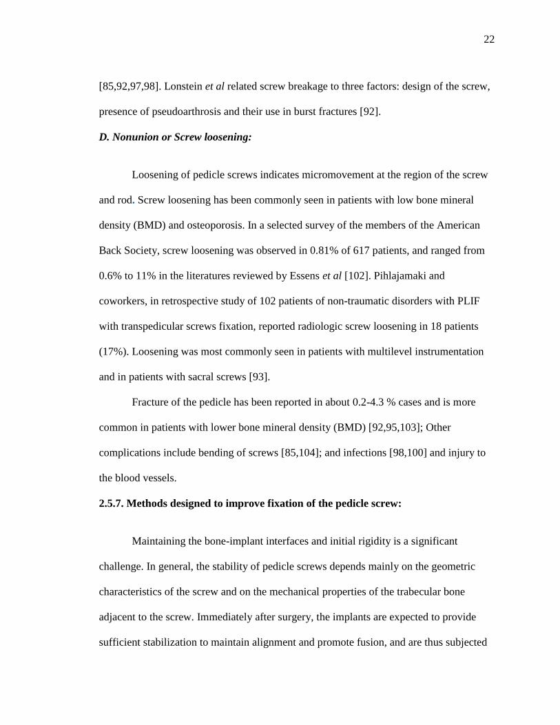
22
[85,92,97,98]. Lonstein et al related screw breakage to three factors: design of the screw,
presence of pseudoarthrosis and their use in burst fractures [92].
D. Nonunion or Screw loosening:
Loosening of pedicle screws indicates micromovement at the region of the screw
and rod. Screw loosening has been commonly seen in patients with low bone mineral
density (BMD) and osteoporosis. In a selected survey of the members of the American
Back Society, screw loosening was observed in 0.81% of 617 patients, and ranged from
0.6% to 11% in the literatures reviewed by Essens et al [102]. Pihlajamaki and
coworkers, in retrospective study of 102 patients of non-traumatic disorders with PLIF
with transpedicular screws fixation, reported radiologic screw loosening in 18 patients
(17%). Loosening was most commonly seen in patients with multilevel instrumentation
and in patients with sacral screws [93].
Fracture of the pedicle has been reported in about 0.2-4.3 % cases and is more
common in patients with lower bone mineral density (BMD) [92,95,103]; Other
complications include bending of screws [85,104]; and infections [98,100] and injury to
the blood vessels.
2.5.7. Methods designed to improve fixation of the pedicle screw:
Maintaining the bone-implant interfaces and initial rigidity is a significant
challenge. In general, the stability of pedicle screws depends mainly on the geometric
characteristics of the screw and on the mechanical properties of the trabecular bone
adjacent to the screw. Immediately after surgery, the implants are expected to provide
sufficient stabilization to maintain alignment and promote fusion, and are thus subjected

23
to high loads in this immediate postoperative period [105]. Inadequate anchorage of the
pedicle screws through the pedicle creates increased and prolonged stresses at the bone-
screw interface, resulting in osteolysis and implant failure. These conditions have been
particularly evident in patients with low bone mineral density (BMD) and osteoporosis
[4, 106], neuromuscular disorders and post-radiation therapy [107]. High failure rates due
to inadequate fixation strength at the pedicle screw-bone interface are also a significant
problem especially in longer lumbar constructs [108]. Other factors that influence the
bony purchase and subsequent fixation strength of a pedicle screw include insertion site
and technique, depth of penetration, pedicle screw diameter, and screw design
characteristics [109,110]. Several strategies have been developed to augment pedicle
screw fixation in mechanically demanding situations.
Some researchers introduced an alteration in the design of the screw. Polly et al
found that increasing the diameter of the salvage screw by 2 mm caused an increase in
insertional torque by 8.4%, whereas increasing the length of the screw did not result in
any improvements of insertional torque [111]. Skinner et al [112] biomechanically
assessed and compared four designs of pedicle screws. The results showed that the pull-
out strength of the screw increased with an increase in the major diameter of the screw,
whereas an increase in the pitch caused increased amount of displacement prior to
failure. The idea of sacral screw fixation using a hollow screw has also been proposed.
The hollow screw supposedly increases contact area with the surrounding bone both on
the outer and inner surface of the screw, potentially improving fixation within trabecular
bone. Schramm et al [113] demonstrated superior pull-out strength with a novel hollow
screw when inserted into the trabecular bone of thoracic vertebral bodies. McLachlin et al

24
also used a novel hollow screw design in a sacral model under cyclic loading and
concluded that the hollow screw was less resistant to loosening in comparison with the
conventional solid pedicle screw [108].
Other orthopedic surgeons have applied alteration in the anatomic trajectory of
placement of the pedicle screw to attain augmentation. Currently, two popular methods
for insertion of pedicles screws are used: straight-forward technique, in which the sagittal
trajectory of the screw parallels the superior endplate of the vertebral body, and the
anatomic trajectory, which is directed 22° in the cephalo-caudal direction in the sagittal
plane and parallels the anatomic axis of the pedicle [114]. Lehman et al compared the
results of the straight-forward technique with the anatomic technique and showed that
straight-forward technique resulted in a 39% increase in maximum insertional torque and
a 27% increase in pull-out strength compared to the anatomic technique [114]. Another
option to obtain better purchase was proposed in the lumbar spine by Zindrick et al [115].
They used pedicle screws which penetrated the anterior cortex of the vertebral body.
Although this procedure is associated with a significant risk, it has demonstrated to add
approximately 30% to the pull-out of a cancellous screw in the lumbar spine, although a
lot of risk is associated with this procedure. The use of laminar hooks concurrently with
the pedicle screws in vitro has shown an enhancement in the rigidity of pedicle screw
fixation [116, 10]. Other novel augmentation methods suggested in the literature include
the use of an expansive pedicle screw design, an expandable anchor and an interlocking
screw [109, 117, 118].
In recent years, various bone cements like poly(methylmethacrylate) cement
(PMMA), calcium sulfate and calcium phosphate cement have revealed an increase in the

25
pedicle screw fixation strength [10]. PMMA has been used as a pedicle filler for
augmentation of the screw path during revision surgery [8,9]. Pfeifer and colleagues
compared the effects of PMMA, milled bone, and matchstick cancellous bone in
augmentation of revision pedicle screws. The injection of PMMA was found to be the
most effective augmentation method, increasing the pull-out strength to approximately
150% of the initial pull-out strength [8]. However there were potential dangers associated
with its use due to its high polymerization temperature; toxicity of the monomer and
immune reactions associated with it [119].
Calcium sulfate cement was used as an alternative to PMMA because it
demonstrated strength similar to PMMA but was without the major risks. It is an
osteoconductive substance, which unlike tricalcium phosphate (TCP) and hydroxyapatite,
is completely absorbed by the body. Derincek et al [7] demonstrated that calcium sulfate
graft augmentation increased the pull-out strength by 1.8 times in a revised screw, in
comparison to the original screw. Similar results were obtained by Yi et al [6], who also
demonstrated that use of injectable calcium sulfate cement not only improved the
immediate pull-out strength significantly, but the effects were maintained even after the
calcium sulfate cement had been completely absorbed.
A possible method to enhance the holding strength of implants is to use coating
with plasma-sprayed osteoconductive materials like hydroxyapatite (HA) [11,12,13].
Short-term studies of HA coating in both orthopedic devices and oral implants have
shown favorable tissue reactions with improved bone-implant contact and holding
strength. Sanden et al used an animal model to compare the biomechanical properties of
HA coated and uncoated pedicle screws [11]. When compared with the uncoated screws,

26
HA coating was associated with a significantly increased pull-out resistance, higher bone-
implant contact and significant decrease in radiolucent zones.
Another method is the use of a titanium plasma sprayed (TPS) screw surface. This
provides a biocompatible, macroporous surface that theoretically promotes a mechanical
interlock between the screw and surrounding bony tissues [120]. The use of HA-TPS
composite coating for pedicle screws to leverage the advantages of both TPS and HA was
considered by Upasani et al [107]. Using the method of torsional screw extraction, the
results showed a greater increase, although not statistically different, in the average peak
torque between 0 and 3 months of postoperative testing in the HA-only (333 N-mm) and
HA-TPS composite coated screws (315 N-mm) compared with the TPS-only screws (57
N-mm). Thus, the combined coating seemed to have a slight additive effect against the
HA coating.
Recently, the use of osteoinductive materials has revolutionized spine surgery.
One way to establish a mechanical connection between the implant and the host skeleton
is regeneration of bone at the interface. The cornerstones for successful bone-healing are
biomechanical stability and biological vitality of the bone, which provides an
environment in which new bone can form [121]. Many conditions, such as insufficient
vascularization, infection, mechanical instability, and systemic diseases like diabetes,
osteoporosis and old age can impair this environment. The new methods to improve
fixation and stability of implants focus on identifying and understanding the factors that
control the regenerating potential of the bone. Various biologics have been used for
enhancement of lumbar fusion surgery over the last decade. One of the most studied and
frequently used to modulate bone apposition on the implant surface is by the use of

27
growth factors. Different growth factors are known to improve osteoblast differentiation
and matrix mineralization, like platelet-derived growth factor [PDGF], bone
morphogenetic proteins (BMPs), insulin-like growth factors (IGF) and basic fibroblast
growth factor (FGF). Among them, BMPs are the most intensively studied group and the
most promising group of growth factors used in the enhancement of bone repair.
2.6. OSTEOINDUCTIVE MATERIALS & BONE MORPHOGENETIC
PROTEINS (BMPs)
BMPs are multifunctional, low molecular weight glycoproteins belonging to the
transforming growth factor beta (TGF-β) superfamily [122]. They are a highly conserved
group of cytokines with widespread expression in various tissues and have a variety of
functions in embryology, development, homeostasis and repair depending on tissue
location and development stage [123]. BMPs can attract various types of cells, and act as
chemotactic, mitogenic or differentiating agents, depending on their concentration
gradients.
2.6.1. History of BMPs:
Bone morphogenetic proteins (BMPs) are a group of osteoinductive growth
factor proteins, meaning that these have the capacity to provide the primordial signal for
the differentiation of undifferentiated mesenchymal stem cells (MSCs) into osteoblasts.
Over a century ago, Nicolas Senn from Rush Medical College, Chicago demonstrated the
use of decalcified bone in the treatment of osteomyelitis [124]. Several years later in
1945, Lacroix related this effect to the presence of osteogenic inducer in the bone termed
as osteogenin [125]. The phenomenon of bone induction, or osteoinduction, was first

28
described by Marshall Urist in 1965 [126], who discovered that new bone formation
occurred locally in rodents after intramuscular implantation of demineralized, lyophilized
rabbit bone. He ascribed this phenomenon to the presence of proteins in bone matrix,
which he termed as bone morphogenetic proteins. Reddi & Huggins implanted particles
of demineralized bone subcutaneously and described the phenomenon of bone
morphogenesis [127].
2.6.2. Classification & Structure of BMP molecule:
In the late 1980s, it was found that BMP is not a single protein but a group of
proteins in the bone matrix that was responsible for osteoinduction. In 1988, Wozney et
al identified the genetic sequence of bone morphogenetic protein, which led to the
identification of its isoforms [128]. With the help of molecular biology techniques, the
structure of more than sixteen different human BMPs has been identified [121,129, 130].
These are designated as BMP-1 to BMP-16 and are divided into several subtypes,
according to structural similarity between the molecules within each subfamily. An
exception to this is BMP-1, which is an enzyme involved in proteolytic processing of
mature collagen [121,130].
Each BMP is a dimeric molecule containing two polypeptide chains which are
held together by a single disulphide bond [130]. Each polypeptide chain is synthesized
from about 400 amino acids. Action of some protease enzymes processes the pro-BMPs
to mature BMPs containing about 120-140 amino acids and seven canonical cysteine
residues. One cysteine residue is involved in formation of interchain disulphide bond and
the other six in each polypeptide chain form three intrachain disulphide bonds [130].

29
2.6.3. Role of BMPs in bone formation:
Only a subset of BMPs has the unique property of inducing de novo bone
formation. These include BMP-2, 4, and 7 [123,131]. These molecules are critical in
development of skeletal tissue by means of their ability to stimulate differentiation and
function of mesenchymal cells to an osteochondroblastic lineage i.e formation of cells
involved in formation and remodeling of bone and cartilage, including osteoblasts,
chondrocytes, and osteoclasts [132]. These proteins activate specific markers of
osteoblastic phenotype (such as production of high levels of alkaline phosphatase (ALP)
activity, type I collagen and osteocalcin), that initiate transformation of mesenchymal
precursors in the musculoskeletal system to osteoblasts and osteoclasts [133]. It has been
postulated that the signaling pathway of osteoblastic differentiation and osteogenesis is a
complex cascade of BMP expression that consists of substantial interaction between the
different types of BMPs and other signaling molecules and receptors [134]. It has been
seen that BMP-2, 4, and 7 use the same serine/threonine kinase receptor complex to
initiate cell-signaling [135].
With the development of bioassay, it has become possible to isolate and purify
BMPs from demineralized bone matrix (DBM) and has permitted identification of
genetic sequence of the BMP. With this genetic information, molecular cloning
techniques and recombinant expression of osteoinductive BMPs has become possible.
This form of BMPs are called recombinant human (rh) BMPs. It has been possible to
produce unlimited quantities of pure form of BMPs, designated rhBMP-1 to rhBMP-9.
Currently, two commercial forms of recombinant BMP are rhBMP-2 (INFUSE;

30
Medtronic Sofamor Danek, Memphis, Tennessee) and the rhBMP-7 or osteogenic
protein -1 (OP-1; Stryker Biotech, Hopkinton, Massachusetts). Although both of these
have osteogenic properties, it is only rhBMP-2 that has been shown to induce osteoblastic
differentiation of mesenchymal stem cells [134] and has demonstrated success in
numerous preclinical studies as well as numerous clinical trials. In addition, other BMPs
or BMP-combination products are being evaluated clinically; among these are isolates of
animal and human BMP implants, BMPx (Sulzer Biologics, Wheat Ridge, Colorado),
BMP-9, etc [136].
2.7. RECOMBINANT HUMAN BONE MORPHOGENETIC PROTEIN -2
(rhBMP-2):
Recombinant human bone morphogenetic protein -2 (rhBMP-2, also known as
dibotermin alfa) is an osteoinductive protein manufactured from the gene which encodes
for human BMP-2 [137]. The rhBMP-2 manufactured for therapeutic purpose in humans
is expressed in Chinese hamster ovary (CHO) cells. Translation of this gene produces a
prepropeptide containing 396 amino acids. This undergoes intracellular proteolytic
processing and yields a mature, 114 amino acids long rhBMP-2 monomer and an
extended form of rhBMP-2 which is 131 amino acids long. RhBMP-2 purified from CHO
cells is a dimer molecule in which two monomers are linked by a disulphide bond [138].
2.7.1. Mechanism of action: Physical & chemical (molecular) basis
The normal process of bone formation comprises a series of events [137,139]. It
starts with the migration and proliferation of osteogenic undifferentiated mesenchymal
cells (MSCs) at and around the site and in the periosteum. Following or in parallel to this,
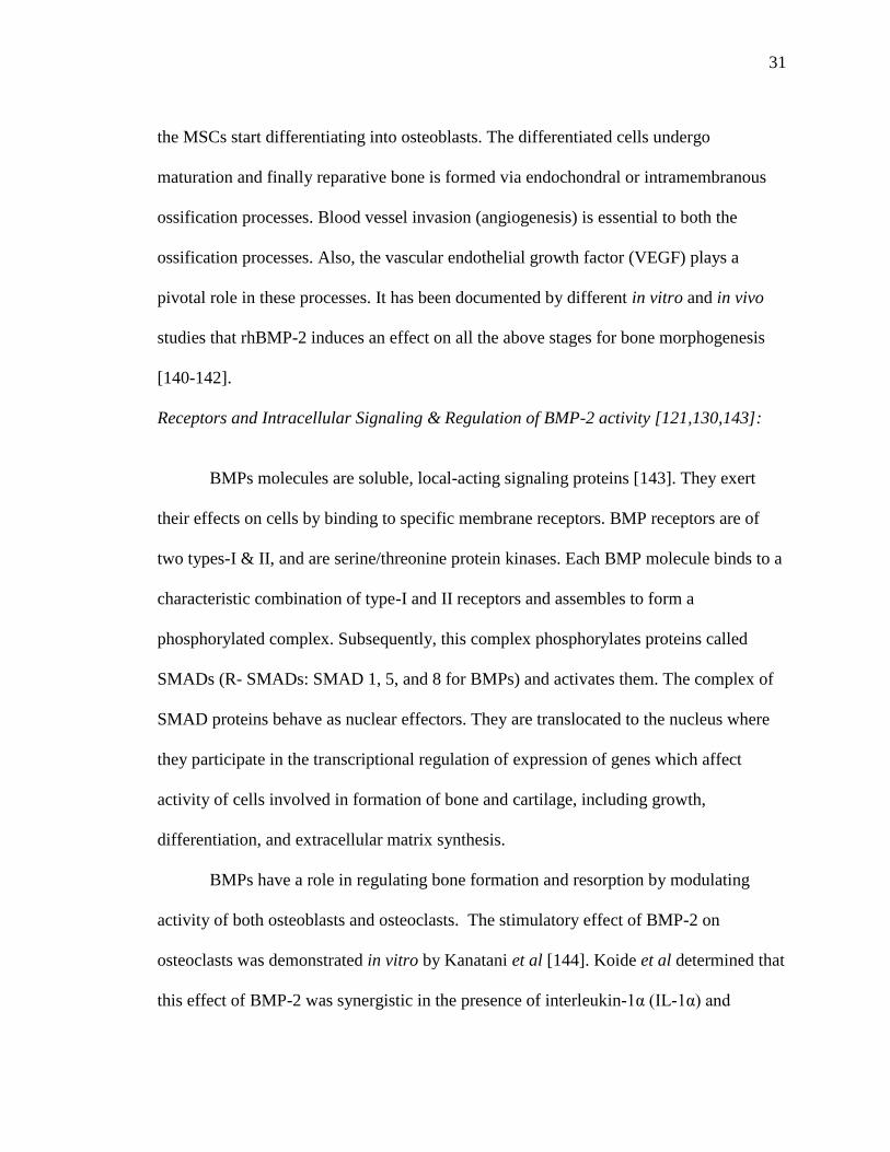
31
the MSCs start differentiating into osteoblasts. The differentiated cells undergo
maturation and finally reparative bone is formed via endochondral or intramembranous
ossification processes. Blood vessel invasion (angiogenesis) is essential to both the
ossification processes. Also, the vascular endothelial growth factor (VEGF) plays a
pivotal role in these processes. It has been documented by different in vitro and in vivo
studies that rhBMP-2 induces an effect on all the above stages for bone morphogenesis
[140-142].
Receptors and Intracellular Signaling & Regulation of BMP-2 activity [121,130,143]:
BMPs molecules are soluble, local-acting signaling proteins [143]. They exert
their effects on cells by binding to specific membrane receptors. BMP receptors are of
two types-I & II, and are serine/threonine protein kinases. Each BMP molecule binds to a
characteristic combination of type-I and II receptors and assembles to form a
phosphorylated complex. Subsequently, this complex phosphorylates proteins called
SMADs (R- SMADs: SMAD 1, 5, and 8 for BMPs) and activates them. The complex of
SMAD proteins behave as nuclear effectors. They are translocated to the nucleus where
they participate in the transcriptional regulation of expression of genes which affect
activity of cells involved in formation of bone and cartilage, including growth,
differentiation, and extracellular matrix synthesis.
BMPs have a role in regulating bone formation and resorption by modulating
activity of both osteoblasts and osteoclasts. The stimulatory effect of BMP-2 on
osteoclasts was demonstrated in vitro by Kanatani et al [144]. Koide et al determined that
this effect of BMP-2 was synergistic in the presence of interleukin-1α (IL-1α) and

32
resulted from increased expression of cyclooxygenase-2 (COX-2) and RANKL mRNA
(receptor activator of nuclear kappaB ligand) in the osteoblasts [145]. Itoh et al [146]
documented a drastic increase in osteoclast formation and differentiation in the murine
bone marrow-derived macrophage cultures treated with RANKL and M-CSF
(macrophage colony stimulating factor).
The activity of BMPs is a highly controlled process. Certain inhibitory proteins
present outside the cell can bind with some BMPs and interfere with their binding to the
cell surface receptors. The activity of BMPs within the cell is controlled through a
combination of both signal-transducing and inhibitory SMAD proteins. BMPs can
upregulate expression of both intra and extracellular proteins and create a negative
feedback loop which limits the activity of BMPs. Thus, the process of bone-induction is
highly controlled and self-limiting. It is seen only locally at the site of BMP and matrix
implantation and until the BMP is present [143].
2.7.2. Carriers of rhBMP-2 & role of carrier in different types of bone deposition:
Because rhBMP-2 molecules are relatively soluble, they are rapidly cleared in
vivo. Therefore, they must be maintained at the planned site until the osteoblastic
differentiation and osteogenesis is under way. The current approach is to use less soluble
carriers to maintain the BMP at the site. The carrier offers several advantages [147,148]:
Localizes rhBMP-2 at the desired site and avoids its rapid diffusion, thus
controlling the release kinetics.
Provides a three-dimensional scaffold for osteogenic cell infiltration and
transformation and defines the volume for newly formed mineralized tissue.

33
It has been observed that the dose needed for an efficacious bone induction was
significantly reduced when rhBMP-2 was used with a carrier.
The reproducibility of the bone induction cascade is also improved when rhBMP-
2 is implanted with biomaterials.
A number of carrier systems have been designed and evaluated for delivery of
rhBMP-2. Some have structural, space-occupying properties (synthetic polymers and
calcium phosphate ceramics). Others provide little structure or space maintenance (type-I
collagen sponge). Some of these structural carriers are porous, calcium compounds, and
have osteoconductive property, like coral and insoluble bone matrix (IBM) [134].
Inorganic materials include ceramics such as hydroxyapatite (HA) and tri-
calcium phosphate (TCP) and calcium phosphate based cements (CPCs). Calcium
phosphate ceramics are highly crystalline, bio-inert materials and get reabsorbed over
time [134]. Both HA and TCP are bioactive ceramics and have been widely used for the
reconstruction of bone defects [149,150].
Among the natural polymers, inactivated demineralized insoluble bone matrix
(DBM) has been the early biomaterial of choice since it was considered to be a natural
substrate. However, it carries serious risk of infection, immunological rejection and viral
transmission [151]. Type-I collagen has been of interest since it is biocompatible,
biodegradable and enhances cellular penetration to form extracellular matrix [152]. An
added advantage of collagen is that it is a natural component of bone whose degradation
and degradation products can be mediated by physiological means [148]. Currently,
sheets of absorbable collagen sponge (ACS), reconstituted from bovine tendon and a
collagen-based matrix, derived from demineralized/guanidine- extracted bovine bone,

34
have been used for the delivery of rhBMP-2 and rhBMP-7, respectively [147]. Since
these type-I-collagen carriers do not provide structural support, they are combined with
calcium phosphate ceramics if a structural scaffold is needed [134].
The most common synthetic polymers are polylactic acid (PLA) and
polyglycolic acid (PGA). These polymers are also used to make bioresorbable implants
and sutures. When used as a BMP carrier, they form a porous, structural scaffold, which
promotes osseous ingrowth and then get absorbed after the fusion mass is established.
Combined PLGA (poly-D, L-lactide-co-glycolide) presents advantages of
biocompatibility and minimal immunogenicity. Furthermore, the lower molecular weight
PLGA offers excellent biodegradability [153]. In a recent study on the dog mandible,
rhBMP-2 was encapsulated in PLGA microspheres and dispersed in a chitosan/collagen
composite scaffold. It was concluded that this sustained carrier scaffold based on
microspheres was more effective to induce implant osseointegration [153]. Researchers
have also used titanium fiber mesh as the carrier material [154,155]. It has excellent
mechanical properties and bone formation can be significantly enhanced by the
deposition of a thin calcium phosphate on its surface.
2.7.3. Preclinical and clinical studies with the use of rhBMP2:
While the use of BMPs has been evaluated in numerous models, spinal
applications continue to receive much interest as the population ages and degenerative
disc diseases become increasingly prevalent. Most preclinical studies evaluating the
safety and efficacy of rhBMP-2 as substitutes for bone graft have shown this to be equal
or superior to autogenous iliac crest bone graft in the lumbar fusion surgery. One of the
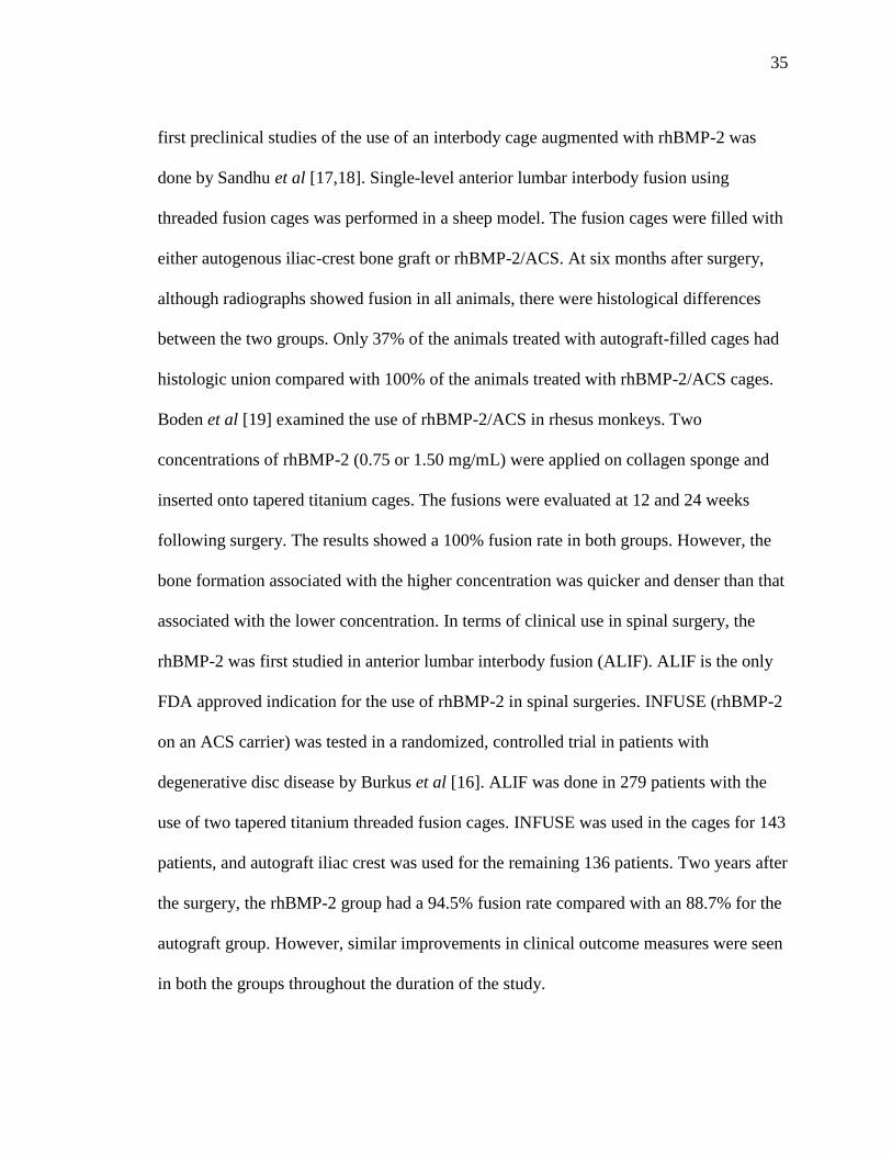
35
first preclinical studies of the use of an interbody cage augmented with rhBMP-2 was
done by Sandhu et al [17,18]. Single-level anterior lumbar interbody fusion using
threaded fusion cages was performed in a sheep model. The fusion cages were filled with
either autogenous iliac-crest bone graft or rhBMP-2/ACS. At six months after surgery,
although radiographs showed fusion in all animals, there were histological differences
between the two groups. Only 37% of the animals treated with autograft-filled cages had
histologic union compared with 100% of the animals treated with rhBMP-2/ACS cages.
Boden et al [19] examined the use of rhBMP-2/ACS in rhesus monkeys. Two
concentrations of rhBMP-2 (0.75 or 1.50 mg/mL) were applied on collagen sponge and
inserted onto tapered titanium cages. The fusions were evaluated at 12 and 24 weeks
following surgery. The results showed a 100% fusion rate in both groups. However, the
bone formation associated with the higher concentration was quicker and denser than that
associated with the lower concentration. In terms of clinical use in spinal surgery, the
rhBMP-2 was first studied in anterior lumbar interbody fusion (ALIF). ALIF is the only
FDA approved indication for the use of rhBMP-2 in spinal surgeries. INFUSE (rhBMP-2
on an ACS carrier) was tested in a randomized, controlled trial in patients with
degenerative disc disease by Burkus et al [16]. ALIF was done in 279 patients with the
use of two tapered titanium threaded fusion cages. INFUSE was used in the cages for 143
patients, and autograft iliac crest was used for the remaining 136 patients. Two years after
the surgery, the rhBMP-2 group had a 94.5% fusion rate compared with an 88.7% for the
autograft group. However, similar improvements in clinical outcome measures were seen
in both the groups throughout the duration of the study.

36
In relation to the preclinical investigations with the use of rhBMP-2 for
posterolateral fusion, one of the first studies was performed in a rabbit model by
Schimandle et al [20]. They reported a 100% fusion rate at four weeks of implantation.
Both biomechanical and histological results showed improved outcome for the rhBMP-2
group compared with the control autograft. In a randomized clinical FDA regulated pilot
study, comparison was made between the posterolateral fusions in three groups of
patients with single-level degenerative disc disease with no greater than Grade-I
spondylolisthesis- patients treated with autograft and pedicle screw fixation; with
rhBMP-2 and pedicle screw fixation; and with rhBMP-2 without pedicle screw fixation
[21]. At an average of seventeen months postoperatively, only 40% of the spines in the
autograft group were fused whereas 100% of those in the groups that had received
rhBMP-2 (both with and without pedicle screw fixation) were fused. Also, rhBMP-2
groups showed earlier and better improvement in patient-derived clinical outcome.
2.7.4. Factors playing a role in action of rhBMP-2:
Several considerations are relevant to the action of bone-inductive agent.
According to Sandhu et al, the efficacy of rhBMP-2 depends on a triad of factors
including site of application, dose or concentration of rhBMP-2 and the type of carrier
used [156].
Because of its greater release kinetics and solubility, rhBMP-2 requires
administration of physiologically high doses or multiple dosages [157]. To prevent this,
delivery systems have been developed for the localized controlled delivery of
biologically active BMPs at the site over the desirable time period. Non human primate

37
studies using lower concentrations of rhBMP-2 on an ACS carrier showed failure of
fusion or less bone formation than did a concentration of 1.5 mg/cm3 [158,159].
According to Boden et al, there generally is a threshold concentration and consistent bone
induction is observed only above this. The threshold value varies with different carrier
matrices, anatomic locations, and animal species [14].
2.7.5. Complications with the use of rhBMP-2:
One of the recent complications with the use of rhBMP-2 has been areas of bone
resorption adjacent to the site of implantation. The first clinical study to report this
finding was by David et al, in which a dose response effect of rhBMP-2 for spinal fusion
was evaluated in a canine model [160]. Areas of rarefaction extending from the fusion
masses into the vertebral bodies were noted in the high dose rhBMP-2 group (860µg)
implanted with a collagen carrier. Histologic analysis of the fusion masses revealed an
absence of lamellar structure, hypercellular trabecular bone with fibrous tissue.
In a retrospective study of 26 patients treated with rhBMP-2 for transforaminal
lumbar interbody fusion (TLIF), McClellan et al [161] reported bone resorption defects
in the CT scans of 22 of the 32 levels reviewed (69%) at an average of 4.4 months (3-7
months) post operatively. Hansen et al [162] demonstrated a case report showing the
resorptive effect of rhBMP-2 with femoral ring allograft (FRA) used for anterior lumbar
interbody fusion. Erosive changes were seen on the CT scans as early as 3 months post
operatively on the superior and inferior end plates and were presumed to be caused by
infection by the surgeons. The FRA’s were however intact. In a prospective cohort study,
Pradhan et al [163] examined the radiographic characteristics of ALIF using FRAs and
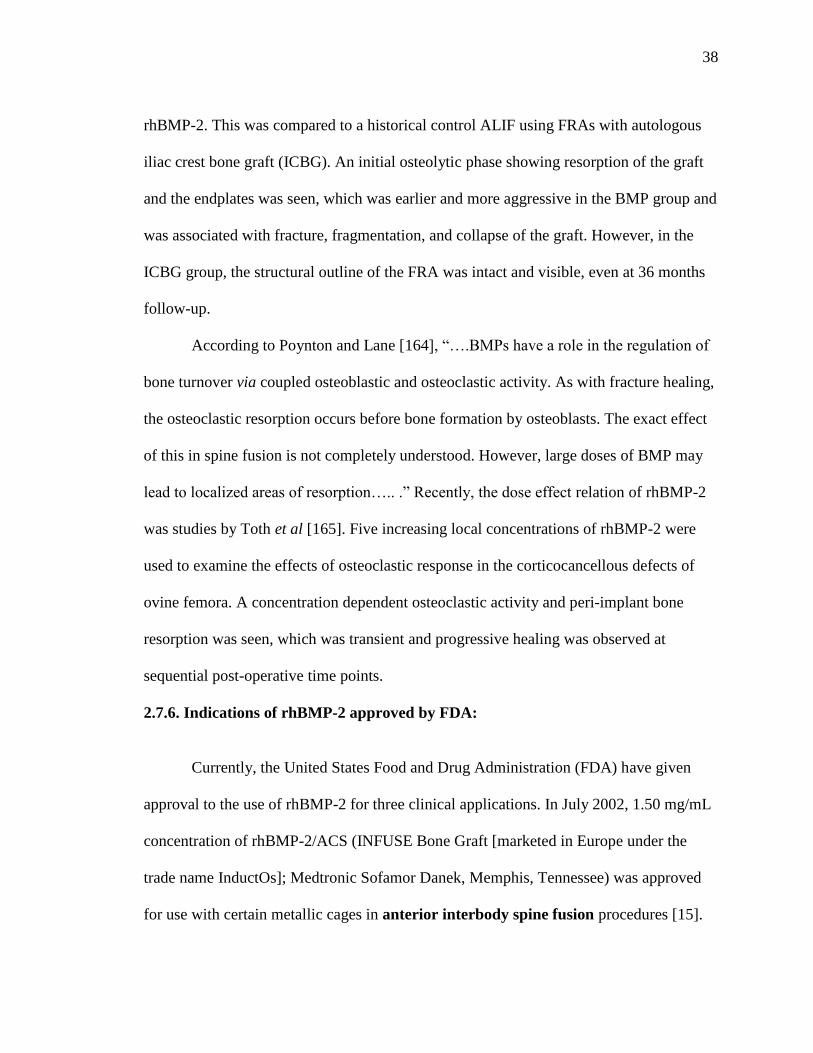
38
rhBMP-2. This was compared to a historical control ALIF using FRAs with autologous
iliac crest bone graft (ICBG). An initial osteolytic phase showing resorption of the graft
and the endplates was seen, which was earlier and more aggressive in the BMP group and
was associated with fracture, fragmentation, and collapse of the graft. However, in the
ICBG group, the structural outline of the FRA was intact and visible, even at 36 months
follow-up.
According to Poynton and Lane [164], ―….BMPs have a role in the regulation of
bone turnover via coupled osteoblastic and osteoclastic activity. As with fracture healing,
the osteoclastic resorption occurs before bone formation by osteoblasts. The exact effect
of this in spine fusion is not completely understood. However, large doses of BMP may
lead to localized areas of resorption….. .‖ Recently, the dose effect relation of rhBMP-2
was studies by Toth et al [165]. Five increasing local concentrations of rhBMP-2 were
used to examine the effects of osteoclastic response in the corticocancellous defects of
ovine femora. A concentration dependent osteoclastic activity and peri-implant bone
resorption was seen, which was transient and progressive healing was observed at
sequential post-operative time points.
2.7.6. Indications of rhBMP-2 approved by FDA:
Currently, the United States Food and Drug Administration (FDA) have given
approval to the use of rhBMP-2 for three clinical applications. In July 2002, 1.50 mg/mL
concentration of rhBMP-2/ACS (INFUSE Bone Graft [marketed in Europe under the
trade name InductOs]; Medtronic Sofamor Danek, Memphis, Tennessee) was approved
for use with certain metallic cages in anterior interbody spine fusion procedures [15].
39
In April 2004, the FDA granted approval to similar concentration of rhBMP-2/ACS in the
treatment of acute, open tibial fractures stabilized with an intramedullary nail fixation
[166]. Recently in March 2007, INFUSE received approval as a bone graft substitute for
augmentation of maxillary sinus floor surgery and augmentation of extraction sockets
[167].
2.8. SHEEP AS A MODEL FOR HUMAN SPINE STUDIES:
2.8.1. Need for an animal model
Before a new spinal implant or biomaterial is used for clinical purpose, in vitro
studies are carried out to test its potential. Although spine specimens from human donors
are preferably used for such tests, they are required in large quantities to overcome the
wide scattering effect associated with biological variability [168]. Therefore, the
availability of human specimens is limited. They also carry a potential risk of infection
and most of them show various signs of degeneration. Therefore, animal models are
regularly used instead. They permit both the biological response of a living system and
the influence of the pathological processes to be taken into account [169]. Such animal
specimens are more readily available and show much better homogeneity than do human
specimens when selected for breed, sex, age, and weight [168]. Specifically, to provide a
model for the human spine, animals such as sheep, goat, pig, calf, and dog have been
used.
2.8.2. Why sheep?

40
In the past several years, there has been an increase in the use of sheep as a model
for spinal research. There are several reasons for this [170]. Sheep are highly docile and
complaint animals. They are easy to house in large numbers and also easy to handle.
Since they are available in large numbers, they can easily be used for large scale studies.
There is also less emotional attachment with sheep as a companion, in comparison to cats
and dogs.
Wilke et al [168] studied the anatomic characteristics of the mature sheep spine
and compared these with existing human data. They found great similarities in the major
dimensions, which were strongest in the thoracic and lumbar regions, although there
were substantial differences in some dimensions. Their results suggested that the sheep
were a reasonable anatomical model for instrumentation affecting the thoracic and
lumbar regions.
Wilke et al determined the quantitative biomechanical properties of the sheep
spine under pure moments in the three main anatomic planes and compared the results
with those from the human spine [171]. Their data showed that cranio-caudal variation in
range of motion for all load directions was qualitatively similar between sheep and
human spine. Based on these biomechanical data, they concluded that ―Sheep was not
only useful as a model for disc surgery or bone healing processes, but could also serve as
an alternative for the evaluation of spinal implants.‖
It was also observed in different studies that ovariectomy in old ewes induced an
increase in bone turnover at 3 months and significant decrease in bone mineral density at
6 months postoperatively [170, 172]. These findings are similar to post menopausal or
ovariectomy induced bone changes in women. Another study showed an increase in

41
activity of bone alkaline phosphatase (BALP) enzyme at 3 months indicative of high
bone turnover, as was in agreement with changes seen in adults, especially women after
menopause or surgical menopause [172]. In a different study, it was observed that
therapeutic treatment with oestradiol prevented bone loss both in ewes and women if
administered immediately after ovariectomy [173].
Sheep has also been used as a model for osteoporosis. Osteoporosis is a slowly
progressive disease, necessitating a study of several years duration to allow for a response
to therapy. An additional goal for research into osteoporosis is designing of prosthetic
devices that will perform optimally in the presence of osteoporotic bone [174]. Although
osteoporosis in sheep is uncommon, several strategies for the induction of osteoporosis
can be applied like estrogen deficiency, calcium- and phosphate-restricted diet,
movement restriction and high-dose steroid treatment [175,176]. Also, the size of sheep
is big enough to allow accommodation of prosthetic implantations.
The histological appearance and remodeling activity of sheep bone are similar
to human bone. The bone of young sheep (less than three to four years-of-age) is
plexiform (combination of woven and lamellar bone). Also, Haversian remodeling has
been seen in sheep at seven to nine years-of-age [170].
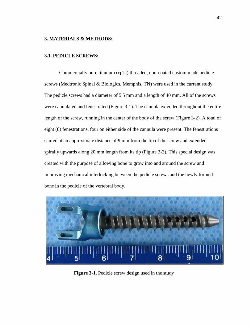
42
3. MATERIALS & METHODS:
3.1. PEDICLE SCREWS:
Commercially pure titanium (cpTi) threaded, non-coated custom made pedicle
screws (Medtronic Spinal & Biologics, Memphis, TN) were used in the current study.
The pedicle screws had a diameter of 5.5 mm and a length of 40 mm. All of the screws
were cannulated and fenestrated (Figure 3-1). The cannula extended throughout the entire
length of the screw, running in the center of the body of the screw (Figure 3-2). A total of
eight (8) fenestrations, four on either side of the cannula were present. The fenestrations
started at an approximate distance of 9 mm from the tip of the screw and extended
spirally upwards along 20 mm length from its tip (Figure 3-3). This special design was
created with the purpose of allowing bone to grow into and around the screw and
improving mechanical interlocking between the pedicle screws and the newly formed
bone in the pedicle of the vertebral body.
Figure 3-1. Pedicle screw design used in the study

43
Figure 3-2. A closer view of the pedicle screw showing the cannula running in the center
of the screw
Figure 3-3. A closer view of the pedicle screw showing the region of fenestrations
44
3.2. RECOMBINANT HUMAN BONE MORPHOGENETIC PROTEIN-2
(RHBMP-2):
RhBMP-2 (Medtronic Spinal & Biologics, Memphis, TN) was reconstituted with
saline for injection at a dose concentration of (0.43 mg/mL). This dose concentration has
been shown to be effective to generate lumbar interbody fusion in sheep. Prior to being
used, the ACS was stored at ambient temperature (15-25 C) and the rhBMP-2 solution
was refrigerated (2-8 C). The rhBMP-2 solution was drip-applied to the absorbable
collagen sponge (ACS). The solution was allowed to soak into the ACS for at least 15
minutes, but for no longer than 2 hours before being implanted. Standard precautions for
handling sterile materials were followed.
3.3. ANIMAL MODEL:
Eight adult (8) non-osteoporotic female sheep of similar age and weight were
used as the animal model for this study. Four lumbar vertebrae from each animal (L2-
L5), with a total of 32 lumbar vertebrae were analyzed. The study received approval
from the Institutional Animal Care and Use Committee (IACUC) at the Thomas D.
Morris Incorporated, Reisterstown, Maryland, 21136. The IACUC approval number is
08-003. The survival phase of this study was directed by Dr. Chetan Patel, William
Beaumont Hospital, Royal Oak, MI. The survival phase did not take place at the Medical
College of Wisconsin or at Marquette University. Only tissues from euthanized sheep
were received. Please see Appendix A for the Marquette University IACUC exemption.
The entire surgical procedure was performed under assisted general anesthesia in
aseptic conditions; using prophylactic antibiotic coverage. The following procedure was
45
followed. First, the destabilization of vertebral bodies was performed with laminectomy
and excision of the facet joints between the 2nd
and 3rd
and the 4th
and 5th
lumbar
vertebrae. Next, the cortical bone was penetrated with an awl, and the pedicle holes were
prepared with a probe and tapped with a 4-mm tap corresponding to the entire screw
length. ACS alone or soaked with rhBMP-2 solution was placed both within and around
the fenestration region. A volume of 0.1 cc of rhBMP-2 was placed in the cannulated
screw and 0.25 cc around the threads of the screw. Therefore, with 0.04 mg and 0.11 mg
respectively, a total dose of ~0.15 mg was delivered per screw. Finally, these
transpedicular screws were applied bilaterally from the second to the fifth lumbar
vertebrae. In their final position, the screws had a slight medial and caudal angulation.
Finally, the vertebrae were stabilized with pedicle screw constructs. Two constructs with
four pedicle screws at each of the L2-3 and L4-5 levels were created with a rod
connecting two pedicle screws without a cross link.
Sheep functional spinal units (FSU) were randomized to four treatment groups.
All four pedicle screws from each functional spinal unit (FSU) contained the same
treatment. Four (4) animals were euthanized at 6 weeks, and four (4) animals at 12 weeks
following surgery and the vertebrae were harvested. The spines were frozen immediately
at the time of sacrifice. The four treatment groups are shown in Table 3-1. The first group
euthanized at 12 weeks, contained pedicle screws with ACS without rhBMP-2. The
second group contained empty pedicle screws without ACS or rhBMP-2, and were
sacrificed at 6 weeks. The first and second groups were designed to serve as controls for
both biomechanical & histological testing. The third and fourth groups were
experimental groups containing rhBMP-2 on an ACS carrier. The third group was

46
sacrificed at 6 weeks and the fourth group at 12 weeks post-operative time period. The
two different treatment times were used to determine the variation in effect of rhBMP-2
with time on the quality and quantity of bone formed. Each animal used in the study was
designated by a number which is listed in Table 3-2.
Table 3-1. Treatment groups and time periods used for the study
Treatment group
Time duration of
treatment
Number of functional
spinal units (FSU)
1. ACS alone-
Control 12 weeks 4
2. Empty- Control 6 weeks 4
3. rhBMP-2/ACS 6 weeks 4
4. rhBMP-2/ACS 12 weeks 4
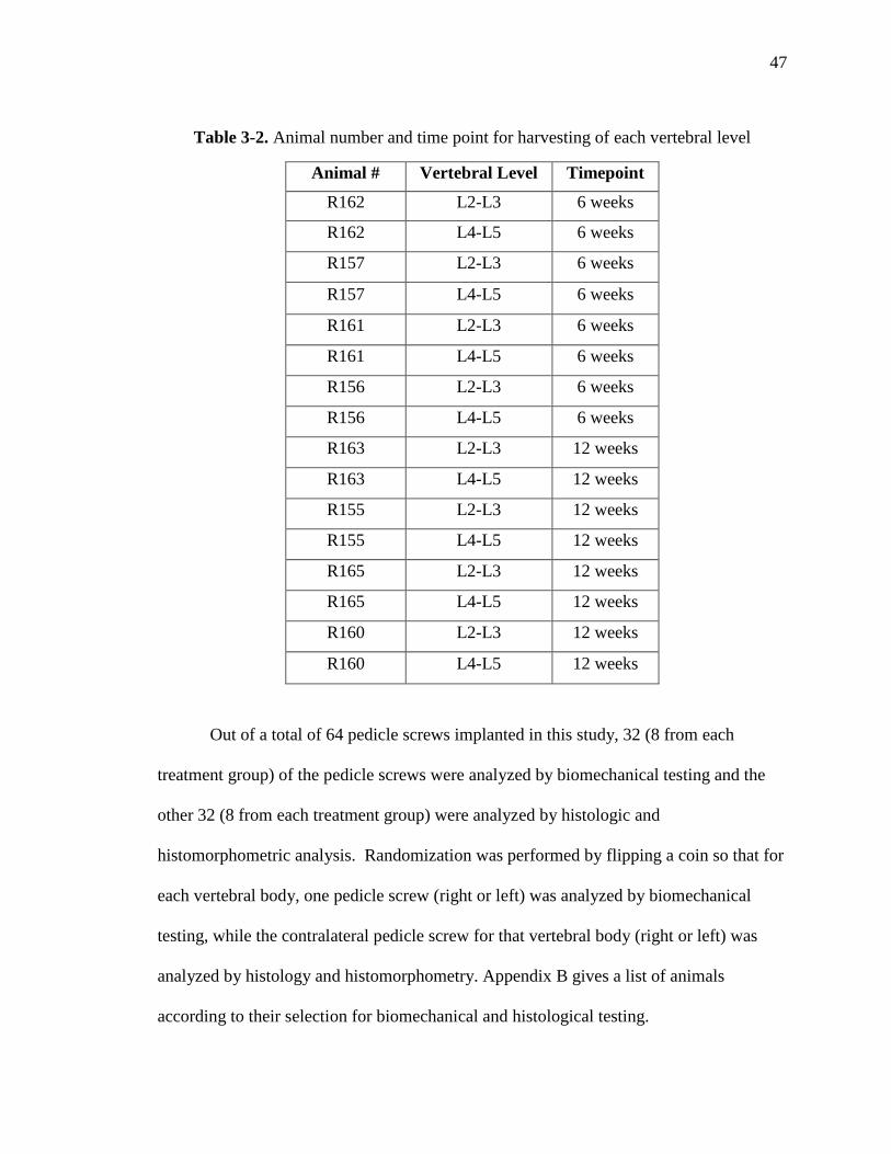
47
Table 3-2. Animal number and time point for harvesting of each vertebral level
Animal # Vertebral Level Timepoint
R162 L2-L3 6 weeks
R162 L4-L5 6 weeks
R157 L2-L3 6 weeks
R157 L4-L5 6 weeks
R161 L2-L3 6 weeks
R161 L4-L5 6 weeks
R156 L2-L3 6 weeks
R156 L4-L5 6 weeks
R163 L2-L3 12 weeks
R163 L4-L5 12 weeks
R155 L2-L3 12 weeks
R155 L4-L5 12 weeks
R165 L2-L3 12 weeks
R165 L4-L5 12 weeks
R160 L2-L3 12 weeks
R160 L4-L5 12 weeks
Out of a total of 64 pedicle screws implanted in this study, 32 (8 from each
treatment group) of the pedicle screws were analyzed by biomechanical testing and the
other 32 (8 from each treatment group) were analyzed by histologic and
histomorphometric analysis. Randomization was performed by flipping a coin so that for
each vertebral body, one pedicle screw (right or left) was analyzed by biomechanical
testing, while the contralateral pedicle screw for that vertebral body (right or left) was
analyzed by histology and histomorphometry. Appendix B gives a list of animals
according to their selection for biomechanical and histological testing.

48
All of the analyses were done in a blinded fashion. The treatment group for each
FSU was unknown to the investigators while the samples were being evaluated and was
revealed after the completion of the analysis.
3.4. METHODS OF ANALYSIS:
Posteroanterior, axial, and lateral plane radiographs of the harvested spines:
Radiographs of the specimens were taken while the specimens were still frozen to
determine screw orientation and location within the vertebral bodies. A Faxitron
(Hewlett Packard, McMinnville, OR) high-resolution radiography unit and high-
resolution film (EKTASCAN B/RA Film 4153, Kodak, Rochester, NY) was used to
produce high-resolution PA and lateral radiographs of the harvested sheep lumbar spines
upon receipt. Faxitron radiographs were scanned using the image analysis software
(Image Pro Plus Software v 5.0, Media Cybernetics, Silver Spring, MD) running on a
Windows XP workstation. A video camera (Model DFC 280, Leica Microsystems,
Cambridge, UK) was used to acquire digital images of the radiographs. These
radiographs were used to confirm the treated levels and screw locations in order to
prepare the specimens for biomechanical testing and to gross the samples for histologic
analysis.
3.4.1. BIOMECHANICAL ASSESSMENT:
On the day of testing, specimens were thawed at room temperature for two hours.
Immediately after thawing, each functional spinal unit (FSU) specimen (either L2-L3 or
L4-L5) was separated into two vertebral bodies on a hacksaw. Axial high-resolution

49
Faxitron radiographs were made of the vertebral body specimens after dissection but
prior to biomechanical testing. The axial images were scanned so that anatomic right is
found on the right side of the image. Radiographs were also scanned so that anatomic
dorsal is found on the top of the image. A video camera (Model DFC 280, Leica
Microsystems, Cambridge, UK) was used to acquire digital images of the axial
radiographs. The biomechanical test was performed on one screw (randomly selected
between the left and the right) leaving the vertebral body intact (Appendix B).
The pull-out test was conducted using a servo hydraulic material testing machine
(MTS model 809, MTS Corp, Eden Prairie, MN). A specially designed pull-out jig was
used to fit to the screw head through the Cotrel-Dobousset (CD) rod and set screw. An
alignment hole was drilled in both the CD rod and the set screw, so a guiding pin from
the jig could be inserted beyond the screw head and into the fenestrated screw. The depth
of this insertion was carefully checked prior to jig assembly to avoid any damage to bony
growth within the screw. Once the screw head and the pull-out jig were secured to the
MTS crosshead, the vertebral body of the specimen was potted in dental cement (Die
Keen Green dental cement, Sullivan Dentals, West Allis, WI, USA) and mounted to the
MTS base (Figure 3-4 A, B). The cement was allowed to set until its initial setting time
of about 45 min-1 hr.
Once the cement was set, the screw was pulled out parallel to its long axis at a
constant displacement rate of 0.5 mm/sec until the screw failed. Failure was defined as
the point where a sharp decrease in the pull-out force was detected. The force applied to
the specimen and corresponding displacement was measured by the built-in load cell and

50
Figure 3-4. Servo hydraulic material testing machine for biomechanical pull-out test of
the pedicle screw A) Final assembly; B) Individual components of the apparatus

51
LVDT of the MTS system. The data was recorded at a rate of 100 Hz using the data
analysis software (TestStar software, MTS Corp, Eden Prairie, MN). Finally, a force-
displacement plot was generated for each tested specimen. For some specimens, the pull-
out test had to be repeated due to incomplete setting and failure of the cement.
For each screw that was tested, a force-displacement plot was generated. From the
above plot, the following three parameters were calculated for each pedicle screw:
1. Maximum pull-out force or pull-out strength (N):
It was defined as the maximum value of force that was attained on the force displacement
curve for each pedicle screw.
2. Pull-out stiffness in the linear region:
It was defined as the initial slope of pull-out of the force-displacement plot in the linear
loading region.
3. Energy absorbed up to the failure point:
It was calculated as the product of pull-out force and displacement up till the point of
failure, or the area under the load-displacement curve till the point of failure.
Statistical Analysis:
Univariate analysis of variance (ANOVA, p=0.05) was performed on the three
biomechanical parameters collected from the pull-out test (maximum pull-out force,
stiffness, and energy absorbed to the point of failure) to determine if there were
differences in the effects produced by treatment groups. When significant findings were
obtained, post hoc Bonferroni/Dunn pair-wise comparisons were conducted at a
significance level of 0.0083 using software (Statview 5.0.1, 92-98, SAS Institute Inc,

52
Cary, NC). Bonferroni/Dunn pair-wise comparison was used for post hoc analysis
because is better suitable since multiple pairs of comparison are involved. It adjusts the p-
values to improve the statistical power with each additional pair-wised comparison.
3.4.2. UNDECALCIFIED HISTOLOGY:
Processing & sectioning of the undecalcified specimens:
Immediately following biomechanical testing, the entire vertebral body was fixed
in 10% formalin so that the contralateral screw in the vertebral body which was not
biomechanically tested could be analyzed by undecalcified histology. All the fixed
vertebral body specimens containing the pedicle screws were grossed using a band saw
(Delta Shopmaster, Model BS100, Delta Machinery, Jackson, TN). The following
portions of the vertebral bodies were removed: (1) Distal 1/3 of the anterior vertebral
body; (2) contralateral side of the vertebral body with pulled out screw; (3) all posterior
elements. Thus, the final block of tissue specimen contained the pedicle screw and the
surrounding tissues (Figure 3-5). All the vertebrae were labeled and processed.
Processing entailed sequentially dehydrating the specimens in graded alcohols, clearing
them in xylene, and embedding them in graded benzoyl peroxide catalyzed methyl
methacrylate according to the schedule in Appendix C. Once the polymerization process
was completed, the specimen blocks were allowed to set in the glass jars until they
hardened (Figure 3-6).

53
Figure 3-5. Grossed specimen of the left side of the vertebral body with the pedicle
screw and its label
Figure 3-6. Processed specimen of the vertebral body and pedicle screw embedded in
methyl methacrylate and labeled

54
The hardened blocks with the embedded screws and the surrounding tissues were
trimmed to remove the excess methyl methacrylate. These were sectioned on a high
speed diamond saw (Buehler Isomet, Lake Bluff, IL) using diamond coated wafering
blades (Buehler Isomet, Lake Bluff, IL) (Figure 3-7). Sections were taken in two planes.
Half of the randomly selected vertebral specimens from each animal were sectioned at
right angle to the long axis of the screw and were labeled as axial specimens (16
screws). The other half of the blocks were sectioned parallel the long axis of the screw
and were longitudinal specimens (16 screws) (Figure 3-8 A,B). Appendix B gives the
orientation selected for sectioning each pedicle screw. Eight (8) specimens that failed
during biomechanical testing were randomly picked and included in the axial and
longitudinal groups (4 in each group) (Appendix B).
Axial sections were taken by sectioning the specimen, beginning from the tip of
the screw and sectioning along the length until the region of fenestration (Figure 3-8 A).
Figure 3-7. Diamond coated wafering blade used for sectioning of the vertebral body
specimens
55
For the longitudinal specimens, radiographs of the entire vertebral body
specimens were taken to help orient the screw axis parallel to the plane of the wafering
blade. Longitudinal sections were taken for the entire screw, by facing the lateral or
medial surface of the vertebral body parallel to the surface of the blade, and continuing
sectioning towards the opposite surface (Figure 3-8 B). Variable weights (200-350
grams) were applied to the blade to obtain an approximate section thickness of 250 µm to
350 µm for both axial and longitudinal sections at a speed of 700 rpm. Approximately
10-20 axial sections and 5-7 longitudinal sections were made from each vertebral body
specimen. The sections were gently rinsed with water to remove any debris and were
dried on a paper towel. The thickness of the sections was measured with a metric
micrometer (Fowler, Japan).
Staining & scanning of the undecalcified sections:
Once the sectioning was completed, the sections were stained with differential
staining using a proprietary trichrome stain. This staining allowed both histological and
cytological differentiation and assessment of the bone into and adjacent to the pedicle
screws. The tissues were differentiated based on color.
Mineralized bone: blue/green
Cartilage and fibrocartilage: dark purple
Fibrovascular tissue: pink
Staining of cellular and nuclear detail by the trichrome stain was similar to Hematoxylin
& Eosin (H&E) staining. Stained undecalcified sections were scanned using the image
analysis software (Image Pro Plus Software v 5.0, Media Cybernetics, Silver Spring,

56
Figure 3-8 A. Alignment of pedicle screw for axial sections- perpendicular to the
direction of sectioning
Figure 3-8 B. Alignment of pedicle screw for longitudinal sections- parallel to the
direction of sectioning

57
MD) running on a Windows XP workstation. A video camera (Model DFC 280, Leica
Microsystems, Cambridge, UK) was used to acquire digital images of the stained
undecalcified sections. For the longitudinal sections, images were scanned in three parts
and were converted into a composite image in the imaging software (Adobe Photoshop
CS2, Version 9.0.2, Adobe System Inc., San Jose, CA).
3.4.3. MICRORADIOGRAPHY
Approximately 2-4 undecalcified sections from each pedicle screw specimen were
selected from both axial and longitudinal specimens, trying to include most of the
sections from the region of interest, i.e. fenestrations and the cannula. For the specimens
showing some defects/cysts in the stained undecalcified images, a greater number of
sections were selected for microradiography.
The selected sections were labeled with ultra-fine permanent markers. These were
placed on spectroscopic film (Ektascan B/RA 4153 film, Kodak, Rochester, NY) and
were radiographed using copper K-alpha radiations at 20 kV and 3 mA, with a
microradiography unit (Faxitron model 43805 radiography unit, Hewlett Packard,
McMinnville, OR). The exposure time was adjusted to approximately 45 seconds for
each 100 µm of the section thickness. These films were then developed and fixed using
an automatic film processor (Gendex GXP, KAB Dental Inc., Warren, MI). These
microradiographs that corresponded to the stained undecalcified sections were analyzed
concurrently with the stained undecalcified sections.
Scanning of microradiographs:

58
Microradiographs were scanned using image analysis software (Image Pro Plus Software
v 5.0, Media Cybernetics, Silver Spring, MD, USA) running on a Windows XP
workstation. A video camera (Model DFC 280, Leica Microsystems, Cambridge, UK)
was used to acquire black and white (8 bit gray scale) digital images of the
microradiographs. Longitudinal microradiographs were scanned in three parts and were
converted into a composite image in imaging software (Adobe Photoshop CS2 9.0.2,
Adobe Systems Inc., San Jose, CA).
With the 8 bit gray scale setting used for microradiography, the implant and bone
could be differentiated due to their different density. The implant, being more radiopaque
appeared white against the black background, and bony trabeculae appeared as varying
shades of gray (Figure 3-9 A, B). A mm scale was placed in the field during scanning
to allow for calibration during subsequent quantitative histomorphometry and line
profile analysis.

59
Figure 3-9. Digital images of radiographs of A) Axial section of animal R156 L4 LT cut
10; B) Longitudinal section of animal R161 L4 RT cut 4. Figure A shows the
radiographic differentiation between the bone and pedicle screw. The fenestrations and
cannula can be seen in Figure B.

60
3.4.4. HISTOMORPHOMETRY
After acquisition of digital images of the microradiographs, histomorphometry
was conducted using image analysis software (Image Pro Plus Software v 5.0, Media
Cybernetics, Silver Spring, MD) running on a Windows XP workstation. To avoid
observation bias, all the measurements were made by a single investigator.
A fixed region of interest (ROI) on the 8-bit gray scale images of the
microradiographs was selected for histomorphometric measurements.
For the axial sections, a circular region with a diameter of 7.5 mm (Area = 44.45
sq.mm) was selected as the region of interest (ROI). The center of the circular ROI
corresponded approximately with the center of the screw, and the circle also included the
peri-implant bone adjacent to the screw (Figure 3-10 A). Every attempt was made to
exclude cortical bone from the measurements. For some sections where the screw was
extending out of the cortical bone of the vertebral body, the shape and area of the circle
was altered to exclude any empty space outside the cortex. The diameter of 7.5 mm was
selected based on the observation that most remodeling was seen within this region
around the pedicle screw.
For the longitudinal sections, a rectangular region of interest (ROI) was chosen
(Figure 3-10 B). The width of the box was 7.5 mm, corresponding to the diameter of the
circular ROI for the axial sections. The length of the box was fixed at 14.0 mm
(approximately the length of first five threads of the pedicle screw). By taking this length
and width of the box, the fenestrations were centered in this region of interest. In this
way, a uniform area of bone around the screw was analyzed (Figure 3-10 B). The length

61
Figure 3-10. Digital images of the regions of interest A) Axial section showing a circle
of diameter 7.5 mm; B) Longitudinal section showing a rectangular box of length 14 mm
and width 7.5 mm
7.5 mm 7.5 mm 7.5 mm

62
of the box for some longitudinal sections was reduced if the screw tip protruded out of
the cortical bone.
Three histomorphometric measurements were made in the respective regions of
interest- quantitative and qualitative assessment of bone for both axial and longitudinal
microradiographic images, and line profile analysis for trabecular thickness in the region
of interest of the longitudinal sections only.
a) Quantitative assessment of percentage area of bone within and around the pedicle
screw in the ROI:
After tracing the region of interest (circle or rectangle), the ―Process
segmentation‖ menu was selected on the image analysis software (Image Pro Plus
Software v 5.0) and was applied to the microradiographic image. The gray scale range
with this software was from 0 to 255. The gray scale range corresponding to the bone
within and around the pedicle screw was determined, such that the pedicle screw and
anything which was not bone was excluded from the measurements. From this gray
scale range corresponding to the bone, a histogram was created using the ―Histogram‖
feature on the Image Pro plus 5.0 software (Figure 3-11 A,B). Finally, the percentage (by
area) bone in the circular or rectangular AOI, divided by the area available for bone
formation was measured. The following data was entered into an excel spreadsheet: area
of circle or rectangle, screw area, percentage area available for bone formation and
percentage area with bone. A screen capture of the image with the histogram was taken
(Figure 3-11 A,B).

63
Figure 3-11. Screen captures of selected gray scale range of bone and a histogram for the
gray scale range in the region of interest for A) Axial section of animal R156 L4 LT cut
13; B) Longitudinal section of animal R156 L5 RT cut 3
64
b) Qualitative assessment of bone density:
The density of bone in the region of interest was assessed using the ―Pseudocolor-
colorize gray scale images‖ feature on the Image Pro plus 5.0 software. Using the same
gray scale range selected for measurement of percentage bone as an internal standard, the
bone in the ROI was differentiated into four equal color coded densities based on gray
scale range:
Division 1 (Red) - Least dense
Division 2 (Yellow) - Less Dense
Division 3 (Green) - More Dense
Division 4 (Blue) - Most dense
Again, this measurement excluded the pedicle screw and intertrabecular spaces
and non-osseous tissues so that the percentage of each division for one section (axial or
longitudinal) corresponded to its percentage out of the total bone (100%) within and
around the screw (Figure 3-12 A,B). The data on percentage of each division of density
into and adjacent to the screw was entered into an excel spreadsheet. A screen capture of
the image with the region of interest and density percentages were taken. An example can
be seen in Figure 3-12 A,B.

65
Figure 3-12. Screen captures of density variations for the selected gray scale range of
bone in the region of interest for A) Axial section of animal R156 L4 LT cut 13; B)
Longitudinal section of animal R156 L5 RT cut 3

66
Statistical Analysis:
The mean percentage of bone within and around the pedicle screw and the mean
of density divisions for each animal were calculated. The data was arranged according to
the treatment groups and was compared using the analysis the of variance (ANOVA) test
(p=0.05). Where significant findings were obtained, further post-hoc Bonferroni/Dunn
pair-wise comparisons at a 0.0083 significance level were conducted using software
(Statview 5.0.1, 92-98, SAS Institute Inc, Cary, NC).
c) Line profile analysis for measurement of trabecular thickness:
A line profile analysis was done to determine the thickness of bony trabeculae in
the ROI of only the longitudinal sections and to compare the thickness of remodeled
trabeculae under the effect of rhBMP-2 with the trabecular thickness of control groups.
Gray scale (8-bit) images of the longitudinal microradiographs were opened with
the Image Pro Plus Software v 5.0. A black and white mask was prepared from these
images using the same gray scale range used for quantitative measurement of the
percentage bone for histomorphometry. The gray scale range was slightly modified for
some sections to include any bony trabeculae which were not completely counted in the
gray scale range. White areas corresponded to bone (trabeculae and cortical bone) and
black areas corresponded to anything which was not being counted as bone (soft tissue,
marrow, empty spaces etc) (Figure 3-13 A).
Following this, each black and white mask image was calibrated using the mm
scale that was placed with the image during microradiography. To obtain values for
thickness of individual trabeculae, a Line Profile tool was used in the Image Pro Plus
A

67
Figure 3-13 A) Digital image showing a black and white mask for longitudinal section of
animal R156 L5 RT cut 3. The same gray scale range used for histomorphometry, was
used for preparing the mask
Software v 5.0. Two horizontal lines, 10 mm long (approximately the length of 4 threads
of the pedicle screw), 1 mm above and below the tip of the threads were used for each
longitudinal section (Figure 3-13 B, D). Each line was centered approximately over the
region of fenestration. For sections in which the screw was extending outside of the
cortical bone, the length of the line was altered to exclude the cortex or anything outside
the bone.
A line profile graph was obtained for each line as shown in Figure 3-13 B, D. The

68
Figure 3-13 B) Digital image of a longitudinal section of animal R156 L5 RT cut 3 with
a 10 mm long superior line and plateau and valley like line profile graph. The plateaus
represent bony trabeculae C) Table with line profile data for the superior line
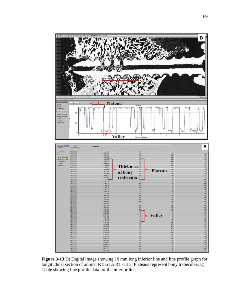
69
Figure 3-13 D) Digital image showing 10 mm long inferior line and line profile graph for
longitudinal section of animal R156 L5 RT cut 3. Plateaus represent bony trabeculae; E)
Table showing line profile data for the inferior line

70
shape of the line profile was in the form of plateaus and valleys. The plateaus
corresponded to the bony trabeculae (white regions) and the valleys corresponded to
anything outside the trabeculae (black region). Since the image was calibrated, the x-axis
of the line profile graph directly reported width of the trabeculae as fraction of a
millimeter. Each line reported the width of several trabeculae that it crossed. The data
from the line profile were transferred into an excel spreadsheet (Figure 3-13 C, E). Excel
macros were used to determine the average width of bony trabeculae from each section.
From this, average width of bony trabeculae for each animal was calculated. Finally, the
data were arranged according to the treatment groups and average trabecular width was
determined.
Statistical analysis:
The data of trabecular width for each treatment group was compared using the
analysis of variance (ANOVA) test with a significance of 0.05. Where significant
findings were seen, further post-hoc comparisons, using Bonferroni/Dunn pair-wise
comparisons at significance level of 0.0083 were conducted by software (Statview 5.0.1,
92-98, SAS Institute Inc, Cary, NC).

71
4. RESULTS:
4.1. BIOMECHANICAL ASSESSMENT
A majority (30 out of the 32) screws were randomly selected for biomechanical
testing. Two screws were not randomly selected for biomechanical testing. The right screws
in the L2 and L3 vertebral bodies of animal R161 were selected for biomechanical pull-out
test because of the significant lateral placement of the left screws.
Out of the 32 screws tested for biomechanical pull-out, eight (8) failed before the
screw could be completely pulled out. The mode of failure was either by fracture of the
screw head from the shaft or through fracture of the screw shaft at one of the fenestrated
holes. The mode of failures for the screws that had failed prior to the completion of
biomechanical testing is listed in Table 4-1. In all the eight cases, the same definition of
pull-out strength was applied; i.e. the peak force achieved before the first drop in force
magnitude.
In the rhBMP-2/ACS 6 weeks group, four screws from one animal (R157) were
removed from the biomechanical analysis as outliers. The reason for excluding these
samples from biomechanical analyses was that the data collected from these individual
samples was two times less than the group mean (the group mean was calculated with the
outliers included) and therefore these samples were defined as "outliers". Similarly, one
screw each from of the ACS alone 12 weeks (R165 L5 RT) and rhBMP-2/ACS 12 weeks
(R165 L3 RT) was removed as an outlier. These are listed in Table 4-2. For all the six
outliers from the two animals, radiolucencies were seen in association with the screws on
their axial view radiographs (Figure 4-1. A,B). With these outliers removed, the number

72
of specimens for analysis were n=4 for the rhBMP-2/ACS 6 weeks, and n=7 for ACS
alone 12 weeks and rhBMP-2/ACS 12 weeks.
Table 4-1. Failure type of the eight screws
Table 4-2. List of outliers
Failure Type Animal Level Treatment
Fractured screw
head
R162
L3 RT Empty 6 weeks
L4 RT Empty 6 weeks
L5 LT Empty 6 weeks
R160 L4 RT ACS alone 12 weeks
Broken screw
shaft
R160
L2 LT ACS alone 12 weeks
L3 LT ACS alone 12 weeks
L5 LT ACS alone 12 weeks
R156 L2 RT Empty 6 weeks
Animal Level Treatment
R157
L2 rhBMP-2/ACS 6 weeks
L3 rhBMP-2/ACS 6 weeks
L4 rhBMP-2/ACS 6 weeks
L5 rhBMP-2/ACS 6 weeks
R165 L5 ACS alone 12 weeks
R165 L3 rhBMP-2/ACS 12 weeks

73
Figure 4-1 A. Axial view (with anatomical right on the right side of the image) of the
four vertebral bodies of animal R157 (rhBMP-2/ACS 6 weeks). The screws used for
pull-out test were L2 right (top left), L3 left (top right), L4 left (bottom left), and L5 right
(bottom right). Pointer showing radiolucency in association with the screw
Figure 4-1 B. Axial view (with anatomical right on the right side of the image) of the two
vertebral bodies of animal R165 L5 RT (ACS alone 12 weeks) and R165 L3 RT (rhBMP-
2/ACS 12 weeks). Pointer showing radiolucency associated with the screw

74
From the data of biomechanical testing, a load displacement plot was generated
for each pedicle screw. A representative load displacement plot of animal R163 L4 RT is
shown in Figure 4-2. The results of the three biomechanical parameters are listed below.
4.1.1. Pull-out Strength:
Individual screw pull-out strengths (in Newtons) are listed in Table 4-3. The
mean (±SD) pull-out strength of the four treatment groups (with the same 6 outliers
removed) are graphically represented in Figure 4-3.
Empty 6 weeks demonstrated the highest pull-out strength (3717.9±932.1 N),
while rhBMP-2/ACS 6 and 12 weeks groups are in the low 2000 N (2074.1±907.8 N and
2330.4±549.7 N, respectively). ACS alone group had pull-out strength 3191.5 ±728.4 N
which was higher than both the 6 and 12 weeks rhBMP-2/ACS groups.
Figure 4-2. Load displacement curve generated using software from the biomechanical
pull-out data of animal R163 L4 RT

75
Table 4-3. Individual screw pull-out strength (in Newtons). The outliers are highlighted
in yellow
Treatment Screw
Animal/Level/Side
Pull-out Strength
(N)
Empty 6wks R156 L2R 4251.2
Empty 6wks R156 L3L 3433.2
Empty 6wks R161 L4L 2418.7
Empty 6wks R161 L5L 2227.0
Empty 6wks R162 L2L 4189.9
Empty 6wks R162 L3R 4728.8
Empty 6wks R162 L4R 4260.7
Empty 6wks R162 L5L 4234.0
rhBMP-2/ACS 6wks R156 L4R 2282.0
rhBMP-2/ACS 6wks R156 L5L 3258.6
rhBMP-2/ACS 6wks R157 L2R 425.3
rhBMP-2/ACS 6wks R157 L3L 166.1
rhBMP-2/ACS 6wks R157 L4L 121.0
rhBMP-2/ACS 6wks R157 L5R 122.1
rhBMP-2/ACS 6wks R161 L2R 1209.7
rhBMP-2/ACS 6wks R161 L3L 1546.1
ACS alone 12wks R155 L2L 3757.7
ACS alone 12wks R155 L3L 3896.0
ACS alone 12wks R160 L2L 3776.7
ACS alone 12wks R160 L3L 3423.7
ACS alone 12wks R160 L4R 2936.6
ACS alone 12wks R160 L5L 2610.6
ACS alone 12wks R165 L4R 1939.5
ACS alone 12wks R165 L5R 150.7
rhBMP-2/ACS 12wks R155 L4R 2965.8
rhBMP-2/ACS 12wks R155 L5L 2373.5
rhBMP-2/ACS 12wks R163 L2L 1400.6
rhBMP-2/ACS 12wks R163 L3L 2354.5
rhBMP-2/ACS 12wks R163 L4R 2375.6
rhBMP-2/ACS 12wks R163 L5R 1909.7
rhBMP-2/ACS 12wks R165 L2L 2932.9
rhBMP-2/ACS 12wks R165 L3R 141.2

76
Figure 4-3. The mean (±SD) pull-out strength of the pedicle screws among the four
treatment groups
ANOVA showed that significant differences existed between the four treatment
groups (p=0.0041, ANOVA). Post hoc Bonferroni/Dunn tests demonstrated that the
Empty 6 weeks group had significantly higher pull-out strength than both rhBMP-2/ACS
6 weeks (p<0.0024, Bonferroni/Dunn) and rhBMP-2/ACS 12 weeks (p<0.0025,
Bonferroni/Dunn). There were no significant differences between the other groups.
4.1.2. Pull-out Stiffness:
Complete individual screw pull-out stiffness data (including the outliers) of
individual screws is presented in Table 4-4. Figure 4-4 is a graphical presentation of the
mean (±SD) pull-out stiffness of the four treatment groups, excluding the outliers.

77
Table 4-4. Individual screw pull-out stiffness (in N/mm). The outliers are highlighted in
yellow
Treatment Screw
Animal/Level/Side Stiffness (N/mm)
Empty 6wks R156 L2R 1591.8
Empty 6wks R156 L3L 2057.6
Empty 6wks R161 L4L 1277.9
Empty 6wks R161 L5L 860.1
Empty 6wks R162 L2L 1729.7
Empty 6wks R162 L3R 2042.5
Empty 6wks R162 L4R 1275.7
Empty 6wks R162 L5L 1754.8
rhBMP-2/ACS 6wks R156 L4R 994.7
rhBMP-2/ACS 6wks R156 L5L 1300.7
rhBMP-2/ACS 6wks R157 L2R 276.1
rhBMP-2/ACS 6wks R157 L3L 175.2
rhBMP-2/ACS 6wks R157 L4L 120.8
rhBMP-2/ACS 6wks R157 L5R 72.1
rhBMP-2/ACS 6wks R161 L2R 1117.7
rhBMP-2/ACS 6wks R161 L3R 825.3
ACS alone 12wks R155 L2L 1586.9
ACS alone 12wks R155 L3L 1920.1
ACS alone 12wks R160 L2L 1157.5
ACS alone 12wks R160 L3L 2471.3
ACS alone 12wks R160 L4R 2387.3
ACS alone 12wks R160 L5L 1340.1
ACS alone 12wks R165 L4R 1328.2
ACS alone 12wks R165 L5R 130.5
rhBMP-2/ACS 12wks R155 L4R 1625.3
rhBMP-2/ACS 12wks R155 L5L 1482.8
rhBMP-2/ACS 12wks R163 L2L 1420.2
rhBMP-2/ACS 12wks R163 L3L 1534.3
rhBMP-2/ACS 12wks R163 L4R 1592.5
rhBMP-2/ACS 12wks R163 L5R 1426.9
rhBMP-2/ACS 12wks R165 L2L 1496.2
rhBMP-2/ACS 12wks R165 L3R 71.0

78
Figure 4-4. The mean (±SD) pull-out stiffness of the pedicle screws among the four
treatment groups
The ACS alone 12 weeks group showed the highest stiffness (1741.6±528.9
N/mm) and the rhBMP-2/ACS 6 weeks group demonstrated the lowest stiffness value
(1059.6±200.5 N/mm). With ANOVA, no significant differences could be determined
between any of the four treatment groups (p=0.05, ANOVA).
Since the significance level was 0.05, a post hoc Bonferroni/Dunn pairwise
comparison was conducted. This demonstrated significant difference in stiffness between
the ACS alone 12 weeks group and rhBMP-2/ACS 6 weeks group (p=0.0077,
Bonferroni/Dunn). Although, the rhBMP-2/ACS 12 weeks group (1511.2±78.1 N/mm)
showed an improvement in stiffness over the rhBMP-2/ACS 6 weeks (1059.6±200.5
N/mm), significance level could not be attained (p=0.0652, Bonferroni/Dunn). Also,
there were no significant differences between the other groups.

79
4.1.3. Energy absorbed to the point of failure:
The mean (±SD) energy absorbed up to the failure point of the four treatment
groups is presented in Figure 4-5 (with the same 6 outliers removed as in the pull-out
strength testing). Complete individual screw pull-out energy data (including the outliers)
is listed in Table 4-5.
On average, the highest energy needed to pull-out the screws is from the Empty 6
weeks group (5.9±2.4 Nm). The rhBMP-2/ACS 12 weeks group showed the lowest
required energy (2.4±1.0 Nm), despite the improved stiffness over the rhBMP-2/ACS 6
weeks. Significant differences between the amount of energy absorbed to failure were
demonstrated among the groups with ANOVA (p=0.0064, ANOVA). However, only
Figure 4-5. The mean (±SD) energy absorbed up to point of failure among the four
treatment groups

80
Table 4-5. Individual screw pull-out energy data (in N-m). The outliers are highlighted in
yellow
Treatment Screw
Animal/Level/Side Energy (N-m)
Empty 6wks R156 L2R 8.12
Empty 6wks R156 L3L 3.60
Empty 6wks R161 L4L 2.99
Empty 6wks R161 L5L 3.29
Empty 6wks R162 L2L 7.82
Empty 6wks R162 L3R 8.20
Empty 6wks R162 L4R 7.95
Empty 6wks R162 L5L 5.53
rhBMP-2/ACS 6wks R156 L4R 3.48
rhBMP-2/ACS 6wks R156 L5L 4.94
rhBMP-2/ACS 6wks R157 L2R 0.36
rhBMP-2/ACS 6wks R157 L3L 0.11
rhBMP-2/ACS 6wks R157 L4L 0.08
rhBMP-2/ACS 6wks R157 L5R 0.09
rhBMP-2/ACS 6wks R161 L2R 0.80
rhBMP-2/ACS 6wks R161 L3R 2.01
ACS alone 12wks R155 L2L 4.87
ACS alone 12wks R155 L3L 4.51
ACS alone 12wks R160 L2L 7.22
ACS alone 12wks R160 L3L 2.94
ACS alone 12wks R160 L4R 2.28
ACS alone 12wks R160 L5L 2.66
ACS alone 12wks R165 L4R 1.87
ACS alone 12wks R165 L5R 0.12
rhBMP-2/ACS 12wks R155 L4R 3.47
rhBMP-2/ACS 12wks R155 L5L 2.45
rhBMP-2/ACS 12wks R163 L2L 0.94
rhBMP-2/ACS 12wks R163 L3L 2.63
rhBMP-2/ACS 12wks R163 L4R 2.68
rhBMP-2/ACS 12wks R163 L5R 1.42
rhBMP-2/ACS 12wks R165 L2L 3.03
rhBMP-2/ACS 12wks R165 L3R 0.22

81
the Empty 6 weeks and rhBMP-2/ACS 12 weeks groups were significantly different
(p<0.0011, Bonferroni/Dunn). The other groups were statistically similar to each other.
4.2. HISTOMORPHOMETRY:
For the axial specimens, a total of 20 screws were analyzed for
histomorphometry, including two screws in which the head separated from the screw
during biomechanical testing (R160 L4 RT and R160 L5 LT) and two screws in which
the shaft broke (R156 L2 RT and R160 L2 LT) during biomechanical testing. For the
longitudinal specimens, 18 screws were used for histomorphometric analysis, including 2
screws in which the head separated from the screw during biomechanical testing (R162
L3 RT and R162 L4 RT) during biomechanical pull-out testing. The two screws with a
broken shaft (R160 L3 LT and 160 L5 LT) included in the longitudinal group, were
examined by undecalcified histology, but were excluded as outliers from
histomorphometric analysis. The following parameters were analyzed by
histomorphometry - quantitative (percentage bone in available area of region of interest)
and qualitative analysis of bone (density range of bone in the region of interest) as well as
line profile analysis (trabecular thickness in the region of interest).
4.2.1. Quantitative analysis (Percentage bone in the region of interest):
Axial specimens:
The screen captures of quantitative histomorphometry for the representative
animals from four treatment groups is presented in Figure 4-6 A-D. The mean (±SD)
highest amount of bone formation in the circular region of interest (ROI) with an

82
approximate area of 44.2 mm2 was seen for the Empty 6 weeks group (71.4±3.1%), and
lowest amount of bone formation was seen for the rhBMP-2/ACS 6 weeks group
(52.0±18.1%). For the ACS alone 12 weeks and rhBMP-2/ACS 6 weeks group, the area
of bone was 68.7±21.3% and 58±15.9%, respectively (Figure 4-7). The data from
individual animals are listed in Table 4-6. It can be observed that the amount of bone
formed increased from the 6 weeks to the 12 weeks time point for the rhBMP-2/ACS
group. However, significant differences were not found among the four treatment groups
(p=0.2379, ANOVA).
Figure 4-6 A. Quantitative histomorphometry (AXIAL) screen capture for the Empty 6
weeks animal R162 L5 LT cut 15

83
Figure 4-6 B. Quantitative histomorphometry (AXIAL) screen capture for the rhBMP-
2/ACS 6 weeks animal R156 L4 LT cut 13
Figure 4-6 C. Quantitative histomorphometry (AXIAL) screen capture for the ACS alone
12 weeks animal R155 L2 RT cut 8

84
Figure 4-6 D. Quantitative histomorphometry (AXIAL) screen capture for the rhBMP-
2/ACS 12 weeks animal R163 L2 RT cut 5
Figure 4-7. The mean (±SD) percentage bone formation in the circular region of interest
for the axial specimens among the four treatment groups

85
Table 4-6. Individual data and mean (±SD) of percentage bone formation in the circular
region of interest for the axial specimens among the four treatment groups
Treatment group ANIMAL AVG %AVG/ group StDev
Empty 6wks R156 L2 RT 70.5
71.4 3.1
Empty 6wks R156 L3 RT 70.9
Empty 6wks R161 L5 RT 73.6
Empty 6wks R162 L3 LT 72.4
Empty 6wks R162 L4 LT 66.1
Empty 6wks R162 L5 LT 75.0
rhBMP-2/ACS 6wks R156 L4 LT 67.5
52.0 18.1 rhBMP-2/ACS 6wks R157 L2 LT 43.3
rhBMP-2/ACS 6wks R157 L4 RT 30.6
rhBMP-2/ACS 6wks R161 L2 LT 66.4
ACS alone 12wks R155 L2 RT 69.3
68.7 21.3
ACS alone 12wks R160 L2 LT 73.6
ACS alone 12wks R160 L3 RT 86.0
ACS alone 12wks R160 L4 RT 76.2
ACS alone 12wks R160 L5 RT 80.4
ACS alone 12wks R165 L4 LT 26.9
rhBMP-2/ACS 12wks R155 L5 RT 65.5
58.0 15.9 rhBMP-2/ACS 12wks R163 L2 RT 71.6
rhBMP-2/ACS 12wks R165 L3 LT 35.2
rhBMP-2/ACS 12wks R163 L5 LT 59.8

86
Longitudinal specimens:
The screen captures of quantitative histomorphometry for the representative
animals from four treatment groups is presented in Figure 4-8 A-D. Similar to the axial
specimens, the mean (±SD) highest amount of bone formation in the rectangular region
of interest (ROI) with an area of 105 mm2 was observed for the Empty 6 weeks group
(57.4±3.3%). For the rhBMP-2/ACS 6 weeks group, these values were the lowest with
only 37.2±14.7% of the area with bone formation. Significant difference could not be
reached among the four treatment groups (p=0.0569, ANOVA). Figure 4-9 is a graphical
representation of the mean (±SD) percentage bone for the longitudinal specimens and the
data are individually listed in Table 4-7.
Figure 4-8 A. Quantitative histomorphometry (LONGITUDINAL) screen capture for the
Empty 6 weeks animal R161 L4 RT cut 5
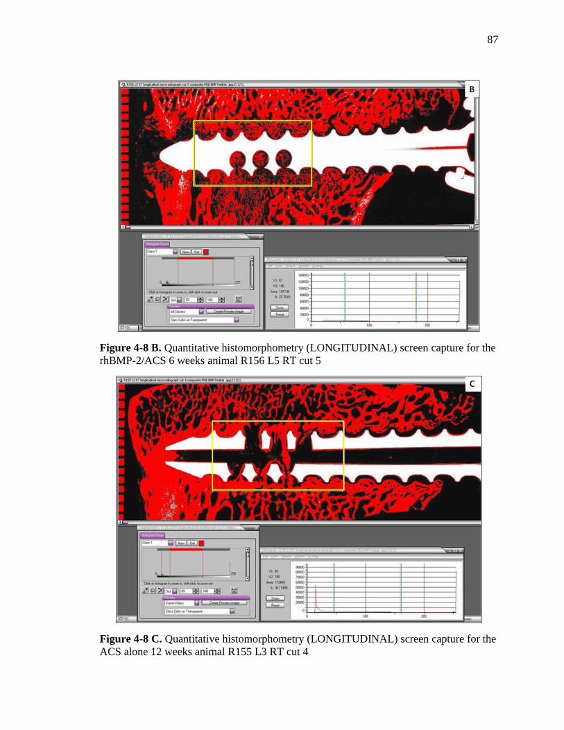
87
Figure 4-8 B. Quantitative histomorphometry (LONGITUDINAL) screen capture for the
rhBMP-2/ACS 6 weeks animal R156 L5 RT cut 5
Figure 4-8 C. Quantitative histomorphometry (LONGITUDINAL) screen capture for the
ACS alone 12 weeks animal R155 L3 RT cut 4

88
Figure 4-8 D. Quantitative histomorphometry (LONGITUDINAL) screen capture for the
rhBMP-2/ACS 12 weeks animal R155 L4 LT cut 5
Figure 4-9. The mean (±SD) percentage bone formed in the rectangular region of interest
for the longitudinal specimens among the four treatment groups

89
Table 4-7. Individual data and mean (±SD) percentage bone formed in the rectangular
region of interest for the longitudinal specimens among the four treatment groups
Treatment group ANIMAL AVG % AVG/
group
StDev
Empty 6wks R156 L2 LT 54.2
57.4 3.7
Empty 6wks R161 L4 RT 59.8
Empty 6wks R162 L2 RT 59.8
Empty 6wks R162 L3 RT 62.0
Empty 6wks R162 L4 RT 52.9
Empty 6wks R162 L5 RT 55.8
rhBMP-2/ACS 6wks R156 L5 RT 47.3
37.2 16.9 rhBMP-2/ACS 6wks R157 L3 RT 28.6
rhBMP-2/ACS 6wks R157 L5 LT 17.9
rhBMP-2/ACS 6wks R161 L3 LT 54.9
ACS alone 12wks R155 L3 RT 59.7
54.7 19.8 ACS alone 12wks R160 L2 RT 69.5
ACS alone 12wks R160 L4 LT 64.0
ACS alone 12wks R165 L5 LT 25.6
rhBMP-2/ACS 12wks R155 L4 LT 46.8
39.1 5.3 rhBMP-2/ACS 12wks R163 L3 RT 37.5
rhBMP-2/ACS 12wks R163 L4 LT 34.5
rhBMP-2/ACS 12wks R165 L2 RT 37.7
4.2.2. Qualitative analysis (Bone density variations in the region of interest):
Axial specimens:
Although no significant difference was observed in the amount of bone formed in
the region of interest between the treatment groups, there were significant differences in
the quality of bone in the ROI. Table 4-8 and Figure 4-10 present a comparative analysis
of the four grades of bone density for each treatment group for the axial specimens.
Figures 4-11 A-D are the screen capture images of the representative animals from each
treatment group.

90
Table 4-8. The mean (±SD) percentage bone in each of the four density divisions in the
circular region of interest for the axial specimens
Empty 6wks rhBMP-2/ACS
6wks
ACS alone
12wks
rhBMP-2/ACS
12wks
Division 1 29.3±5.5 45.5±4.5 22.2±5.6 31.5±2.4
Division 2 32.6±4.2 27.7±4.9 34.9±6.1 30.2±0.6
Division 3 28.5±4.5 16.1±4.6 33.7±4.7 29.3±2.7
Division 4 6.8±1.3 6.4±3.2 6.4±3.1 9.0±1.4
Figure 4-10. The graphical representation of the mean (±SD) percentage bone in each of
the four density divisions in the circular region of interest for the axial specimens

91
Figure 4-11 A. Screen capture (AXIAL) showing percentage bone in the four density
divisions for the Empty 6 weeks animal R162 L5 LT cut 15
When the bone quality between the treatment groups was compared, there were
significant differences in the lowest density (Division 1) and the higher density (Division
3). The area covered with the hypodense lowest density bone (Division 1) was
significantly greater in the rhBMP-2/ACS 6 weeks group (45.5±4.5%) in comparison to
the ACS alone 12 weeks (p<0.0001, Bonferroni/Dunn); Empty 6 weeks (p=0.0001,
Bonferroni/Dunn) and rhBMP-2/ACS 12 weeks (p=0.001, Bonferroni/Dunn). The area
with higher density bone (Division 3) was significantly lower in the rhBMP-2/ACS 6
weeks group (16.1±4.6%) in comparison to the ACS alone 12 weeks (p<0.0001,
Bonferroni/Dunn); Empty 6 weeks (p=0.0004, Bonferroni/Dunn) and rhBMP-2/ACS 12
weeks (p=0.0005, Bonferroni/Dunn) groups.
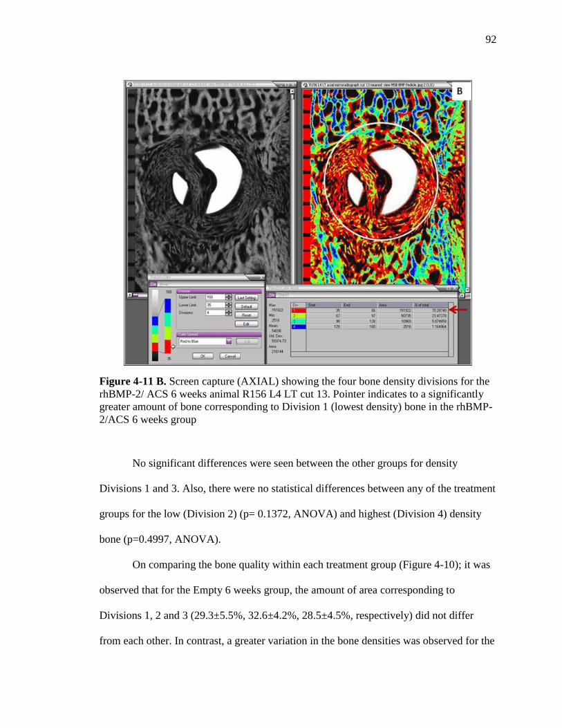
92
Figure 4-11 B. Screen capture (AXIAL) showing the four bone density divisions for the
rhBMP-2/ ACS 6 weeks animal R156 L4 LT cut 13. Pointer indicates to a significantly
greater amount of bone corresponding to Division 1 (lowest density) bone in the rhBMP-
2/ACS 6 weeks group
No significant differences were seen between the other groups for density
Divisions 1 and 3. Also, there were no statistical differences between any of the treatment
groups for the low (Division 2) (p= 0.1372, ANOVA) and highest (Division 4) density
bone (p=0.4997, ANOVA).
On comparing the bone quality within each treatment group (Figure 4-10); it was
observed that for the Empty 6 weeks group, the amount of area corresponding to
Divisions 1, 2 and 3 (29.3±5.5%, 32.6±4.2%, 28.5±4.5%, respectively) did not differ
from each other. In contrast, a greater variation in the bone densities was observed for the

93
Figure 4-11 C. Screen capture (AXIAL) showing percentage bone in the four density
divisions for the ACS alone 12 weeks animal R155 L2 RT cut 8
Figure 4-11 D. Screen capture (AXIAL) showing percentage bone in the four density
divisions for the ACS alone 12 weeks animal R163 L2 RT cut 5

94
rhBMP-2/ACS 6 weeks group. This group had the maximum area (45.5±4.5%) with
Division 1 i.e. hypodense lowest density bone compared to the other divisions (see
pointer in Figure 4-11 B). An improvement was observed in the rhBMP-2/ACS 12 weeks
group with a decrease in area of hypodense bone (31.5±2.4%) and an increase area with
the higher densities in Divisions 2, 3 and 4. The ACS alone 12 weeks group had a greater
area with bone densities from Divisions 2 and 3 (34.9±6.1 and 33.7±4.7, respectively) in
comparison to Division 1 (22.2±5.6%).
Longitudinal specimens:
Similar to the axial specimens, there were significant differences in the quality of
bone in the rectangular ROI for the longitudinal specimens. The data is listed in Table 4-9
and graphically presented in Figure 4-12. Figures 4-13 A-D are the screen captures of the
representative animals from each treatment group.
Table 4-9. The mean (±SD) percentage bone in each of the four density divisions in the
circular region of interest for the longitudinal specimens
Empty 6wks
rhBMP-2/ACS
6wks
ACS alone
12wks
rhBMP-2/ACS
12wks
Division 1 34.7±4.8 49.6±7.5 26.3±3.7 38.4±7.8
Division 2 33.3±3.4 26.6±3.1 31.9±3.4 31.0±2.0
Division 3 23.5±4.6 15.2±3.1 30.7±3.0 22.1±6.4
Division 4 8.5±2.3 8.7±3.3 11.2±3.1 8.5±3.3
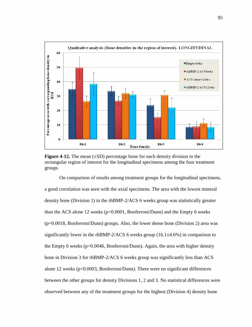
95
Figure 4-12. The mean (±SD) percentage bone for each density division in the
rectangular region of interest for the longitudinal specimens among the four treatment
groups
On comparison of results among treatment groups for the longitudinal specimens,
a good correlation was seen with the axial specimens. The area with the lowest mineral
density bone (Division 1) in the rhBMP-2/ACS 6 weeks group was statistically greater
than the ACS alone 12 weeks (p<0.0001, Bonferroni/Dunn) and the Empty 6 weeks
(p=0.0018, Bonferroni/Dunn) groups. Also, the lower dense bone (Division 2) area was
significantly lower in the rhBMP-2/ACS 6 weeks group (16.1±4.6%) in comparison to
the Empty 6 weeks (p<0.0046, Bonferroni/Dunn). Again, the area with higher density
bone in Division 3 for rhBMP-2/ACS 6 weeks group was significantly less than ACS
alone 12 weeks (p<0.0003, Bonferroni/Dunn). There were no significant differences
between the other groups for density Divisions 1, 2 and 3. No statistical differences were
observed between any of the treatment groups for the highest (Division 4) density bone

96
Figure 4-13 A. Screen capture (LONGITUDINAL) showing percentage bone in the four
density divisions the Empty 6 weeks animal R161 L4 RT cut 5
Figure 4-13 B. Screen capture (LONGITUDINAL) showing percentage bone in the four
density divisions for the rhBMP-2/ACS 6 weeks animal R156 L5 RT cut 5
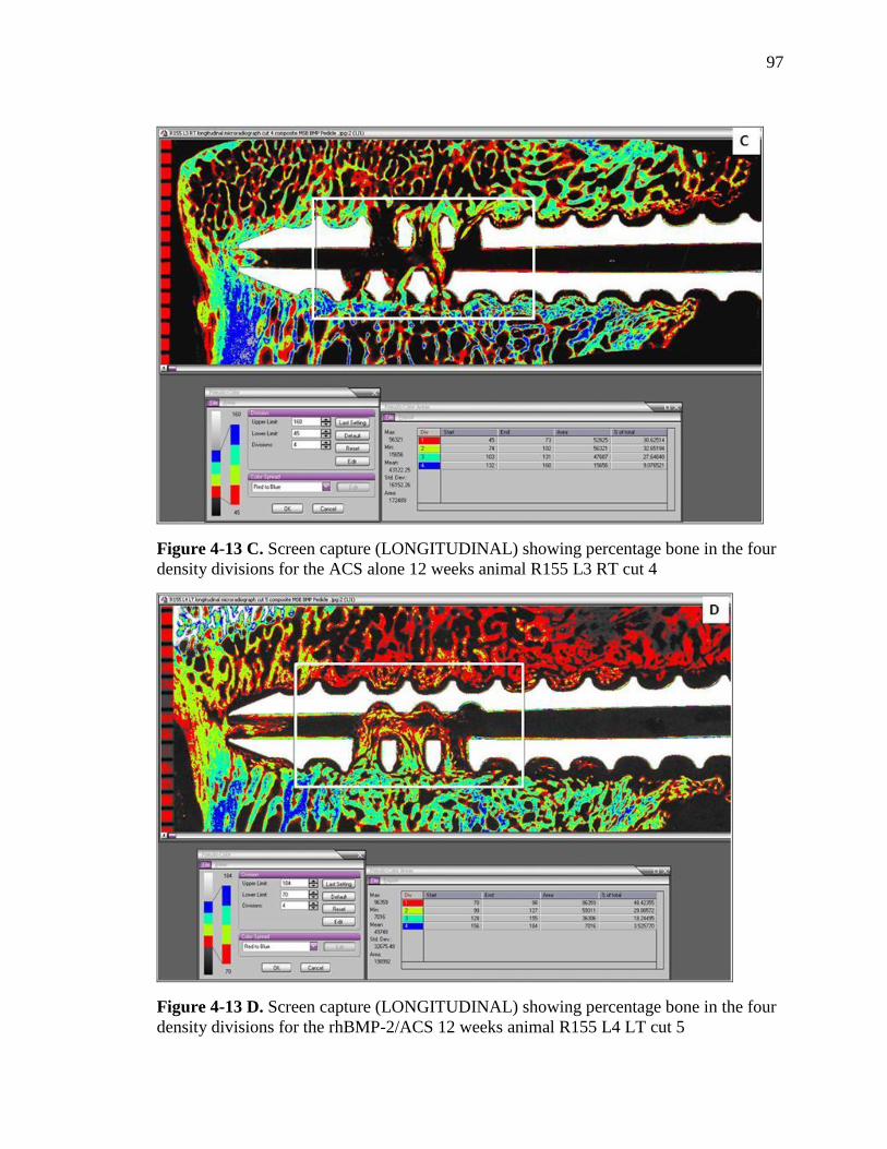
97
Figure 4-13 C. Screen capture (LONGITUDINAL) showing percentage bone in the four
density divisions for the ACS alone 12 weeks animal R155 L3 RT cut 4
Figure 4-13 D. Screen capture (LONGITUDINAL) showing percentage bone in the four
density divisions for the rhBMP-2/ACS 12 weeks animal R155 L4 LT cut 5
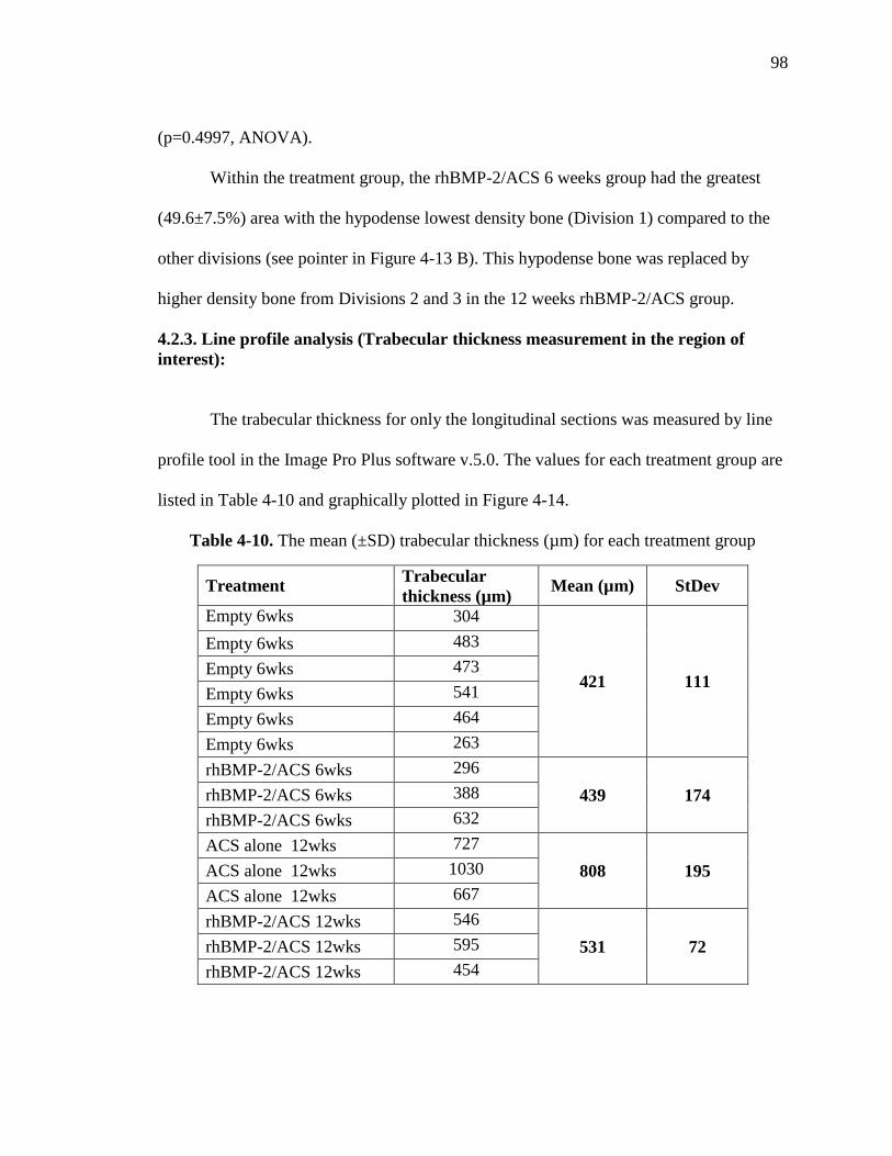
98
(p=0.4997, ANOVA).
Within the treatment group, the rhBMP-2/ACS 6 weeks group had the greatest
(49.6±7.5%) area with the hypodense lowest density bone (Division 1) compared to the
other divisions (see pointer in Figure 4-13 B). This hypodense bone was replaced by
higher density bone from Divisions 2 and 3 in the 12 weeks rhBMP-2/ACS group.
4.2.3. Line profile analysis (Trabecular thickness measurement in the region of
interest):
The trabecular thickness for only the longitudinal sections was measured by line
profile tool in the Image Pro Plus software v.5.0. The values for each treatment group are
listed in Table 4-10 and graphically plotted in Figure 4-14.
Table 4-10. The mean (±SD) trabecular thickness (µm) for each treatment group
Treatment Trabecular
thickness (µm) Mean (µm) StDev
Empty 6wks
304
421 111
Empty 6wks 483
Empty 6wks 473
Empty 6wks 541
Empty 6wks 464
Empty 6wks 263
rhBMP-2/ACS 6wks 296
439 174 rhBMP-2/ACS 6wks 388
rhBMP-2/ACS 6wks 632
ACS alone 12wks 727
808 195 ACS alone 12wks 1030
ACS alone 12wks 667
rhBMP-2/ACS 12wks 546
531 72 rhBMP-2/ACS 12wks 595
rhBMP-2/ACS 12wks 454

99
Figure 4-14. Graph showing mean trabecular thickness (±SD) for the treatment groups
It can be seen from the graph that the ACS alone 6 weeks group had the widest
trabeculae with a mean thickness of about 810 (±195) µm. The thickness of bony
trabeculae in the rhBMP-2/ACS 6 weeks (439±174 µm) and the Empty 6 weeks group
(421±111 µm) was significantly less than the ACS alone 6 weeks group (p=0.0072 and
p=0.0022, respectively, Bonferroni/Dunn).
The data indicates that the remodeled bone which formed in the presence of
rhBMP-2 was osteopenic in comparison the native bony trabeculae. A slight
improvement in the trabecular width was seen from the 6 weeks time point of the
rhBMP-2/ACS group (~440 µm) to the 12 weeks (~530 µm), although statistically
significant differences could not be attained (p=0.4268, Bonferroni/Dunn).

100
4.2.4. Correlation between the biomechanical variables and the different bone
density ranges:
A linear correlation (Pearson’s correlation) was performed between the two
biomechanical variables- stiffness and strength. Similar comparisons were made between
the two most significant bone density Divisions 1 and 3 for the axial specimens.
A moderate and negative correlation was found between the area occupied with
bony trabeculae of the lowest density (Division 1) both within and adjacent to the pedicle
screws and the stiffness (R=-0.66, p=0.0014) and strength (R=-0.58, p=0.0073) (Figure 4-
15 A, B).
In contrast, for the higher density bony trabeculae in Division 3, a moderate and
positive correlation was found between the stiffness and the area with bone quality from
Division 3 (R=0.65, p=0.0019), and a mild to moderate positive correlation was seen with
the pull-out strength of the screws (R=0.48, p=0.032) (Figure 4-15 C, D).

101
Figure 4-15 A, B. A negative correlation between the stiffness and strength of axial
pedicle screws and the percent area of Division 1 weak bone

102
Figure 4-15 C, D. A positive correlation between the stiffness and strength of axial
pedicle screws and the percent area of Division 3 strong bone
103
4.3. UNDECALCIFIED HISTOLOGY:
4.3.1. AXIAL SECTIONS:
A) Empty 6 weeks group:
A total of six screws were analyzed from this treatment group, including two screws
from the biomechanical testing. In two specimens, the antero-lateral positioning of the
pedicle screw resulted in penetration of the anterior and lateral cortex of the vertebral body
and formation of a small bony exostosis surrounding the screw along its entire length.
The most significant finding in the Empty 6 weeks group was the presence of direct
bone contact with the interface of the titanium screw along most of the outer diameter of the
screw (see Figure 4-16 A). Some areas of fatty marrow and thin intervening fibrous tissues
were also observed. The fenestrations and cannulated aspect of the screw was filled with
bone in all the specimens (Figure 4-16 A, B). Microradiographs showed isodense bone in
peri-implant trabeculae in all of the animals (Figure 4-16 A) with thickening and coarsening
of bony trabeculae in two animals (Figure 4-16 B). No evidence of bone resorption, blood-
filled cysts or inflammatory response was seen.

104
Figure 4-16 A. A stained section and corresponding microradiograph of animal R162 L5
LT cut 12 (EMPTY 6 weeks) showing good bone contact on the peri-implant interface
(pointer) and bone formation within the cannula and fenestration (star). Microradiograph
showing isodense bone formation within and around the implant
Figure 4-16 B. A stained section and corresponding microradiograph of animal R156 L2
RT cut 4 (EMPTY 6 weeks) showing coarsening of trabeculae bone in the peri-implant
interface (pointer)

105
B) rhBMP-2/ACS 6 weeks group:
Four screws from three animals were analyzed in this treatment group. There was no
bone contact on the outer diameter and the inner diameter of the pedicle screw for all the
four screws (Figure 4-17 A-F). A thin to thick intervening fibrous tissue band was always
observed along the outer diameter (Figure 4-17 A,B, E, F).
Two screws showed a good amount of remodeled bone within the cannulation and
fenestrations (Figure 4-17 A, B). However, in one of the screws, the remodeled trabeculae
were osteopenic and hypodense with respect to native trabeculae and extended as much as 8
mm away from the screw (Figure 4-17 A). In the other screw, antero-lateral location of the
screw resulted in penetration of cortex and formation of a small bony exostosis around the
screw. This bone and the bone within the cannulation and fenestration was slightly
hypodense (Figure 4-17 B). No evidence of blood-filled cysts or inflammatory response was
observed in relation to these screws.
In the remaining two specimens, no new bone formation was observed within the
cannula or fenestration but few unincorporated bony fragments were seen, especially in the
dorsal aspect of the screw (Figure 4-17 C-F). The pedicle screw was surrounded by a thick
dense fibrous capsule, which was probably the focus of suspected infection (Figure 4-17 D,
F). A blood filled cyst (hematoma) was seen ventral to one screw (Figure 4-17 C), whereas
the other screw was associated with a fluid filled cyst (seroma) approximately 8-12 mm
away from the implant on the caudal and ventral aspect (Figure 4-17 E). The bony
trabeculae proximal to the implant showed remodeling and were hypodense and osteopenic.
The remodeling extended as much as 10 mm away from the screw.

106
Figure 4-17 A. A stained section and corresponding microradiograph of animal R156 L4
LT cut 10 (rhBMP-2/ACS 6 weeks) showing poor bone contact on the peri-implant
interface (yellow pointer) and extensive remodeled bone within the cannula and
fenestration (star). Microradiograph showing that the remodeled bone was osteopenic and
hypodense bone and extended as much as 8 mm from the screw (red pointer)
Figure 4-17 B. A stained section of animal R161 L2 LT cut 9 (rhBMP-2/ACS 6 weeks)
showing poor peri-implant bone contact (yellow pointer) and good amount of remodeled
bone within the cannula and fenestration (star). Microradiograph showing slightly
hypodense remodeled bone in the cannula, fenestration and exostosis (green pointer)

107
Figure 4-17 C. A stained section and microradiograph of animal R157 L2 LT cut 9
(rhBMP-2/ACS 6 weeks) showing poor bone contact on the peri-implant interface
(yellow pointer) and absence of bone within the cannula and fenestration (star).
Hematoma can be seen distal to the screw (red pointer). Microradiograph showing
osteopenic hypodense remodeled bone around the implant and hematoma (green pointer)
Figure 4-17 D. A more dorsal stained section of animal R157 L2 LT cut 14 (rhBMP-
2/ACS 6 weeks) showing a well defined fibrous capsule around the screw (yellow
pointer). Microradiograph showing bony fragments within the cannula (red pointer)

108
Figure 4-17 E. A stained section and microradiograph of animal R157 L4 RT cut 4
(rhBMP-2/ACS 6 weeks) showing poor bone contact with the implant (yellow pointer)
and absence of bone within the cannula (star). Seroma is seen ventral and caudal to the
screw (red pointer). Microradiograph showing osteopenic and hypodense remodeled bone
near the cyst and on the cranial aspect of the screw (green pointer)
Figure 4-17 F. A more dorsal stained section of animal R157 L4 RT cut 13 (rhBMP-
2/ACS 6 weeks) showing well defined fibrous capsule around the screw (yellow pointer).
Microradiograph showing bony fragments within the cannula (red pointer)

109
C) ACS alone 12 weeks group:
In the ACS alone 12 weeks group, six screws were analyzed, two screws from which
were obtained from failed biomechanical analysis.
Five of the six screws showed good to almost exclusive bone contact on the outer
diameter of the screw ventrally (Figure 4-18 A). Moving dorsally, some intervening fibrous
connective tissue was seen at the bone peri-implant interface (Figure 4-18 B). Areas of good
to poor bone contact were observed in the fenestration and within the cannulated aspect of
the screw (Figure 4-18 A, B). Also, some trabeculae showed coarsening at the outer
diameter of the screw (Figure 4-18 A). The amount of mature bone within the fenestrated
and cannulated regions varied from being sparse in some screws to good amounts in others.
Microradiographs showed the isodense peri-implant trabeculae (Figure 4-18 A). There was
no evidence of bone resorption, blood-filled cysts or inflammatory response in these five
screws.
One of the six screws in this group was an exception, and is shown in Figure 4-18 C.
This screw was encapsulated by a layer of thick dense fibrous tissues (>1 mm) along its
entire length, with complete absence of bone contact on any aspect of the screw (inner
diameter, outer diameter, fenestrations). Some unincorporated fragments of bone were seen
in the peri-implant tissues but no new bone formation or bone fragments were observed in
the cannula or fenestrations. No blood-filled cysts were associated with the screw. The bone
adjacent to the fibrous capsule, about 2 mm away from the screw was isodense with respect
to native trabeculae of the vertebral body.

110
Figure 4-18 A. A ventral stained section and microradiograph of animal R160 L3 RT cut
10 (ACS alone 12 weeks) with exclusive bone contact on the peri-implant interface
(yellow pointer) and good amount of within the cannula and fenestration (star).
Microradiograph showing coarse and isodense trabeculae around the screw (red pointer)
Figure 4-18 B. A more dorsal stained section and microradiograph of animal R160 L3
RT cut 14 (ACS alone 12 weeks) showing intervening fibrous connective tissue on the
peri-implant interface (yellow pointer) and sparse bony trabeculae within the cannula and
fenestration (star).

111
Figure 4-18 C. A stained section and microradiograph of animal R165 L4 LT axial cut
10 (ACS alone 12 weeks) showing a capsule of dense fibrous connective tissue on the
peri-implant interface (yellow pointer) and unincorporated bony fragments (red pointer).
D) rhBMP-2/ACS 12 weeks group:
A total of four screws were assessed in this group. There was almost no bone
contact with the inner and outer aspect in all the four pedicles crews, and an intervening
fibrous tissue was always seen along the peri-implant interface (Figure 4-19 A-D).
Three of the four screws had a variable thin to thick layer of intervening fibrous
connective tissue around them (Figure 4-19 A-D). Bony trabeculae were observed, both
surrounding the screw as well as within their fenestrated and cannulated aspects. In one
of the three screws, thick bony trabeculae were observed within the fenestrations and
cannulation and their microradiographs showed isodense peri-implant trabeculae (Figure
4-19 A). For the remaining two screws, slightly hypodense but markedly osteopenic bony

112
trabeculae were seen in the microradiographs and were arranged circumferentially around
the screw. One specimen showed these trabeculae extending in a radius a distance of
about 8-10 mm around the screw (Figure 4-19 B). In the other screw, the remodeling
trabeculae were seen in a radius of about 5-7 mm around the screw and were associated
with small radiolucencies, especially in the dorsal sections (Figure 4-19 C). No bone
resorption or blood-filled cysts were seen.
There was evidence of infection in peri-implant tissues in one screw from the
rhBMP-2/ACS 12 weeks group (Figure 4-19 D). A thick layer of dense fibrous tissues
(>1 mm) was seen ensheathing the entire length of the screw, with complete absence of
bone contact on any aspect of the screw (inner diameter, outer diameter, fenestrations).
There was no new bone formation, but some unincorporated bony fragments were seen in
the peri-implant tissues and in the cannula or fenestrations. The bone adjacent to the
fibrous capsule, about 2 mm away from the screw was isodense with respect to native
trabeculae of the vertebral body. No blood-filled cysts were associated with the screw.
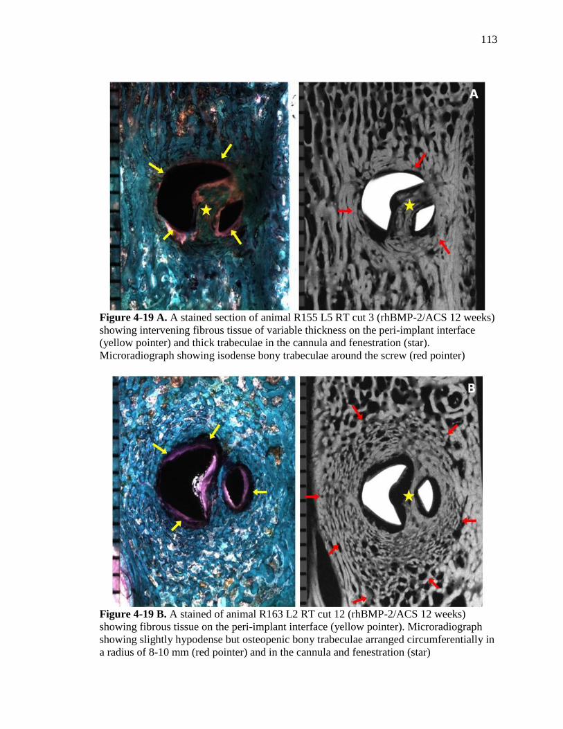
113
Figure 4-19 A. A stained section of animal R155 L5 RT cut 3 (rhBMP-2/ACS 12 weeks)
showing intervening fibrous tissue of variable thickness on the peri-implant interface
(yellow pointer) and thick trabeculae in the cannula and fenestration (star).
Microradiograph showing isodense bony trabeculae around the screw (red pointer)
Figure 4-19 B. A stained of animal R163 L2 RT cut 12 (rhBMP-2/ACS 12 weeks)
showing fibrous tissue on the peri-implant interface (yellow pointer). Microradiograph
showing slightly hypodense but osteopenic bony trabeculae arranged circumferentially in
a radius of 8-10 mm (red pointer) and in the cannula and fenestration (star)

114
Figure 4-19 C. A stained section and microradiograph of animal R163 L5 LT cut 9
(rhBMP-2/ACS 12 weeks) showing poor bone contact on the peri-implant interface and
presence of radiolucencies in dorsal sections (yellow pointer). Microradiograph showing
slightly hypodense but osteopenic bony trabeculae arranged circumferentially in a radius
of 5-7 mm (red pointer) and in the cannula and fenestration (star)
Figure 4-19 D. A stained section of animal R165 L3 LT cut 13 (rhBMP-2/ACS 12
weeks) showing a capsule of dense fibrous connective tissue on the peri-implant interface
(yellow pointer). Microradiograph showing radiolucency with unincorporated bony
fragments (red pointer) and isodense bone 2 mm away from the screw (green pointer)
115
4.3.2. LONGITUDINAL SECTIONS:
A) Empty 6 weeks group:
A total of six screws were analyzed from this treatment group, including two screws
from the biomechanical testing (Figure 4-20 A, B). In three out of six specimens, the pedicle
screw penetrated the ventral cortex screw. These three screws were also positioned far
laterally into the vertebral body and were associated with a bony exostosis laterally. In one
specimen, only the ventral tip of the screw extended past the ventral cortex. Though the
ventral cortex was intact, an exostosis formed adjacent to the protruding screw along the
outer surface of the ventral cortex (Figure 4-20 B).
In general for all the specimens, good bone contact was seen along the titanium
screw interface ventrally, but decreased substantially in the dorsal aspect of the screw for
some specimens and was intervened by fibrous tissues (Figure 4-20 A, B). Good to
moderate amounts of bony trabeculae were found within fenestrations and moderate to very
small amounts in the cannulated aspect of the screw. Direct bone contact was seen in the
fenestrations for some screws, more so in the ventral aspect of the screws. Direct bone
contact is not observed within the cannulated aspect of any of the screws (Figure 4-20 A, B).
A significant finding was the presence of bone fragments adjacent to the screw threads and
in intertrabecular spaces immediately adjacent to the screw in four of the five specimens.
Extensive micro-damage in the form of micro-cracks was also seen in the bone at the screw
thread interface in five of the six screws. This was especially seen in the ventral aspect of the
screw where better bone contact was made with the screw.

116
Figure 4-20 A. A stained section of animal R161 L4 RT cut 4 (EMPTY 6 weeks)
showing good bone contact on the peri-implant interface ventrally (yellow pointer) and
intervening fibrous tissue dorsally (green pointer) and decent bone formation within the
cannula and fenestration (star). Microradiograph showing isodense bone within the
cannula, fenestrations peri-implant area (red pointer and star)
Figure 4-20 B. A stained section of animal R162 L2 RT cut 4 (EMPTY 6 weeks)
showing good bone contact on the peri-implant interface both ventrally and dorsally
(yellow pointer) and decent bone formation within the cannula and fenestration (star)
Microradiograph showing screw extruding the ventral cortex bony exostosis (red pointer)

117
Microradiographs showed isodense bone with normal trabecular thickness in peri-
implant tissues for all the screws in this group. There was no evidence of bone
resorption, any blood-filled cysts or inflammatory response.
B) rhBMP-2/ACS 6 weeks group:
A total of four samples were assessed in this treatment group. In three of the four
specimens, the ventral tip of the screw extended past the ventral cortex. In two of these
screws, a section of the ventral cortex of the vertebral body was missing, not only
anterior to the screw, but also cranial and caudal to it. In the third screw, the screw was
also positioned far laterally with formation of a bony exostosis surrounding it. Bone
contact was absent for all the screws both on the peri-implant interface and within the
cannulation and fenestration (Figure 4-21. A-C).
In three screws, extensive bony remodeling was observed around the screw and in
the region 3-10 mm away from the center of the screw (Figure 4-21 A, B). The
microradiographs showed that these remodeled bony trabeculae were osteopenic and
hypodense with respect to native trabeculae of the vertebral body. In two screws, a good
amount of remodeled bone was also seen in the cannulation and fenestration aspect of
these screws. In the third screw, a significant finding was the presence of a large (10 mm
x 3 mm) blood filled cyst ventral and caudal to the pedicle screw (Figure 4-21 B). Also,
thick intervening fibrous connective tissues were seen adjacent to the entire length of this
screw with presence of bony fragments in the screw threads and in the cannula.
One of the screws showed a characteristic large radiolucent void of the order of
15 mm diameter centered on the fenestrated aspect of the screw (Figure 4-21 C).

118
Figure 4-21 A. A stained section of animal R156 L5 RT cut 4 (rhBMP-2/ACS 6 weeks)
absence of bone contact on the peri-implant interface both ventrally and dorsally (yellow
pointer) and bone within the cannula and fenestration (star). Microradiograph showing
hypodense and osteopenic remodeled bone 3-10 mm from the screw (red pointer) and the
screw penetrating the ventral cortex bony exostosis (green pointer)
Figure 4-21 B. A stained section of animal R157 L3 RT cut 4 (rhBMP-2/ACS 6 weeks)
thick fibrous tissue on the peri-implant interface both ventrally and dorsally (yellow
pointer) and blood filled cyst (red pointer). Microradiograph showing areas of hypodense
and osteopenic remodeled bone within and adjacent to the cyst (star)

119
Figure 4-21 C. A stained section and microradiograph of animal R157 L5 LT cut 6
(rhBMP-2/ACS 6 weeks) showing a large radiolucent void of 15 mm diameter centered
on the fenestrated aspect of the screw (yellow pointer). Areas of remodeling can be seen
on the microradiograph (red pointer).
This void was most likely filled with fluid. No bony remodeling was observed within this
radiolucent void, but microradiographs showed hypodense trabeculae with respect to
native trabeculae limited to the outer aspect of this radiolucent void.
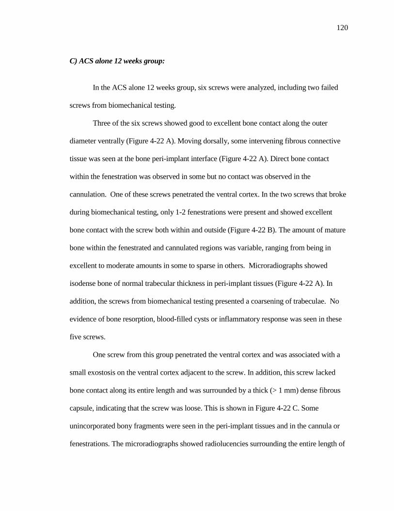
120
C) ACS alone 12 weeks group:
In the ACS alone 12 weeks group, six screws were analyzed, including two failed
screws from biomechanical testing.
Three of the six screws showed good to excellent bone contact along the outer
diameter ventrally (Figure 4-22 A). Moving dorsally, some intervening fibrous connective
tissue was seen at the bone peri-implant interface (Figure 4-22 A). Direct bone contact
within the fenestration was observed in some but no contact was observed in the
cannulation. One of these screws penetrated the ventral cortex. In the two screws that broke
during biomechanical testing, only 1-2 fenestrations were present and showed excellent
bone contact with the screw both within and outside (Figure 4-22 B). The amount of mature
bone within the fenestrated and cannulated regions was variable, ranging from being in
excellent to moderate amounts in some to sparse in others. Microradiographs showed
isodense bone of normal trabecular thickness in peri-implant tissues (Figure 4-22 A). In
addition, the screws from biomechanical testing presented a coarsening of trabeculae. No
evidence of bone resorption, blood-filled cysts or inflammatory response was seen in these
five screws.
One screw from this group penetrated the ventral cortex and was associated with a
small exostosis on the ventral cortex adjacent to the screw. In addition, this screw lacked
bone contact along its entire length and was surrounded by a thick (> 1 mm) dense fibrous
capsule, indicating that the screw was loose. This is shown in Figure 4-22 C. Some
unincorporated bony fragments were seen in the peri-implant tissues and in the cannula or
fenestrations. The microradiographs showed radiolucencies surrounding the entire length of
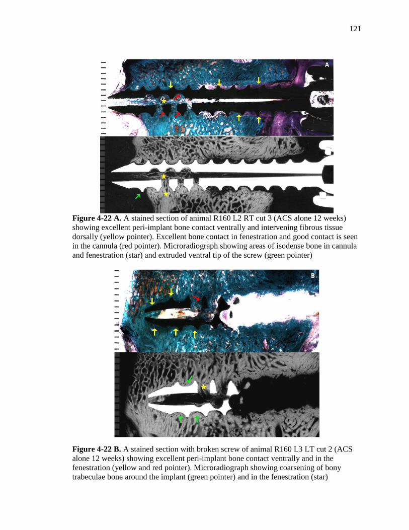
121
Figure 4-22 A. A stained section of animal R160 L2 RT cut 3 (ACS alone 12 weeks)
showing excellent peri-implant bone contact ventrally and intervening fibrous tissue
dorsally (yellow pointer). Excellent bone contact in fenestration and good contact is seen
in the cannula (red pointer). Microradiograph showing areas of isodense bone in cannula
and fenestration (star) and extruded ventral tip of the screw (green pointer)
Figure 4-22 B. A stained section with broken screw of animal R160 L3 LT cut 2 (ACS
alone 12 weeks) showing excellent peri-implant bone contact ventrally and in the
fenestration (yellow and red pointer). Microradiograph showing coarsening of bony
trabeculae bone around the implant (green pointer) and in the fenestration (star)
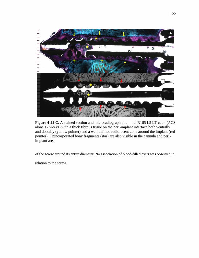
122
Figure 4-22 C. A stained section and microradiograph of animal R165 L5 LT cut 4 (ACS
alone 12 weeks) with a thick fibrous tissue on the peri-implant interface both ventrally
and dorsally (yellow pointer) and a well defined radiolucent zone around the implant (red
pointer). Unincorporated bony fragments (star) are also visible in the cannula and peri-
implant area
of the screw around its entire diameter. No association of blood-filled cysts was observed in
relation to the screw.

123
C) rhBMP-2/ACS 12 weeks group:
In this group, four screws were available for analysis. Two out of four screws
were placed ventral to the ventral cortex of the vertebral body. In general, no bone
contact was seen along the entire length- neither ventrally nor dorsally; and within the
cannulated and fenestrated aspect of the regions of the sections (Figure 4-23 A-C).
Fibrous connective tissues were present at the screw interface with the bone.
In three of the four screws, remodeled bone was seen in the fenestration and
cannulation region. The amount of bone was good in one screw. The other two screws
had only minute amounts on bone within the cannula and fenestration (Figure 4-23 A).
One screw had a small (1.5 mm diameter) blood-filled cyst ventral and left lateral to the
tip of the pedicle screw (Figure 4-23 B). In another screw, a large radiolucent void on the
order of 10-12 mm in diameter was seen centered around the ventral and fenestrated
aspect of the screw (Figure 4-23 C). There appeared to be three smaller cysts filled within
this void and the entire periphery of this void showed an accumulation of blood.
Microradiographs showed isodense bone for the above screws, except for the trabeculae
found in the outer aspect of the radiolucent void, where the trabeculae were hypodense
with respect to native bone (Figure 4-23 A, C).
In one of the four screws, a thick (> 1 mm) dense fibrous capsule was seen around
the entire outer diameter of the screw, indicating a loose screw (Figure 4-22 D). No bony
remodeling was seen, although some unincorporated loose bony fragments were present in
the peri-implant tissues and within the cannula or fenestrations. This is shown in Figure 4-
22 D. There is no evidence of bone contact on any aspect of the screw (inner diameter, outer

124
Figure 4-23 A. A stained section and microradiograph of animal R155 L4 RT cut 5
(rhBMP-2/ACS 12 weeks) showing lack of bone contact and intervening fibrous tissue on
the peri-implant interface both ventrally and dorsally (yellow pointer) and blood filled
cyst (red pointer). Good amount of isodense dense bone can be seen in the cannulated and
fenestrated aspect of the screws (yellow and red stars)
Figure 4-23 B. A stained section and microradiograph of animal R155 L4 RT cut 5
(rhBMP-2/ACS 12 weeks) showing a 1.5 mm diameter blood-filled cyst ventral and left
lateral to the tip of the pedicle screw (yellow pointer)

125
Figure 4-23 C. A stained section and microradiograph of animal R163 L4 LT cut 4
(rhBMP-2/ACS 12 weeks) showing lack of bone contact and intervening fibrous tissue on
the peri-implant interface both ventrally and dorsally (yellow pointer). Three small cysts
can be seen (red pointer) within a large 10-12 mm radiolucent void, with blood on the
periphery (red star). Minute amount of bone can be seen in the cannulated and fenestrated
aspect of the screws (green stars). Microradiograph shows hypodense bone on the outer
aspect of the radiolucent void (yellow stars)
diameter, fenestrations). Microradiographs showed radiolucencies surrounding the entire
screw length all around its diameter (Figure 4-22 D).

126
Figure 4-23 D. A stained section and microradiograph of animal R165 L2 RT cut 5
(rhBMP-2/ACS 12 weeks) showing a thick band of fibrous tissue (>1 mm) on the peri-
implant interface both ventrally and dorsally and a well defined radiolucent zone around
the implant (yellow pointers). Unincorporated bony fragments (red pointers) are also
visible in the cannula and in the peri-implant area

127
5. DISCUSSION:
The effectiveness of pedicle screw instrumentation critically depends on the bone-
screw interface. Instrumentation failure and pseudoarthrosis are particularly common in
patients with low bone mineral density (BMD), often necessitating re-operations. In the
present study, a novel cannulated and fenestrated titanium pedicle screw design was used
to deliver rhBMP-2/ACS with the goals of 1) augmenting the holding power of the
screws, and 2) increasing peri-implant bone formation. The results showed that rhBMP-2
did not significantly improve the biomechanical pull-out properties (stiffness, strength,
and energy) of the pedicle screws at either time period compared to the control groups.
Histomorphometric, histological, microradiographic radiographic findings indicated that
its application was associated with early transient bone resorption, de novo osteopenic
bone, and statistically significant bone density differences at the early time period.
Biomechanical pull-out testing, instead of torsion testing, was performed to
determine the mechanical holding power of the screws. According to Sanden et al,
holding the pedicle screws by connecting rods inhibits their rotation and therefore, pull-
out overloading seems a clinically more relevant mode of failure in comparison to torsion
[177]. Among the most significant factors which affect the biomechanical pull-out
resistance include the outer thread diameter of the screw or the contact area, bone volume
between the threads, and the BMD, especially at the outer end of the threads [61,177].
The pull-out data from this study showed that the highest force and energy for pull-out of
the screw were required by the Empty 6 weeks group. The ACS alone 12 weeks group
demonstrated the highest pull-out stiffness, and the pull-out strength and energy were

128
lower but not significantly different from the Empty 6 weeks group. Correlation of
biomechanical parameters with the histology suggests that this effect was probably
related to good to almost exclusive peri-implant bone contact and good amounts of bone
filling in the cannulation and fenestration regions in these treatment groups. In contrast,
all the screws from the rhBMP-2 treated group lacked direct bone contact and the
histology of the implant- bone interface showed intervening fibrous connective tissues.
Therefore, the biomechanical properties (stiffness, strength, and energy to failure) for the
rhBMP-2 group were inferior to the control groups and thus, the null hypothesis was
rejected. An improvement, although not statistically significant, in the pull-out strength
and stiffness was seen from 6 weeks to 12 weeks in rhBMP-2/ACS group. Thus, the null
hypothesis that the biomechanical properties would improve in the rhBMP-2/ACS
treatment group at a later time period was accepted for these biomechanical variables.
The mean highest pull-out strength of 3717.9 ± 932.1N was demonstrated by the
Empty 6 weeks group, followed by the ACS alone group with pull-out strength 3191.5
±728.4 N. These values were substantially higher in comparison to previous research. A
prior experimental study in adult female sheep spine model demonstrated the mean pull-
out loads (N) of 243 ± 156 N and 2214 ± 578 N for pedicle screws with and without
radiolucent zones, respectively [178]. Suzuki et al determined the effect of coupling on
pull-out strength of empty pedicle screws on 33 osteoporotic cadaveric spines [179]. Pull-
out strengths ranged from 900 N for the uncoupled screws to 1500-1600 N in the single
and double coupler groups. In another study by Klein et al on human cadaver spines, the
average pull-out force for the 6.5 mm screws was 657 ± 424 N [180]. Milcan et al
reviewed the effect of augmentation of pedicle screws with PMMA in adult male sheep

129
lumbar spine and compared the data with empty screws [181]. They obtained pull-out
strengths of about 1550 N for the unaugmented group and about 2550 N for the PMMA
augmented group. The relatively high pull-out strengths for the Empty 6 weeks and ACS
alone 12 weeks group in the current study might be related to the excellent and direct bone
contact and good amounts of bone in the cannula and fenestrations. Moreover, bony
remodeling was also associated with coarsening of trabeculae and radiographic density
similar to the cortical bone were achieved closer to the tip of the screw and the fenestration
aspect. Also, since most of the previous biomechanical pull-out studies as mentioned above,
have been conducted on osteoporotic cadaveric / sheep spines, probability of attaining pull-
out strengths in the range of 3000-3500 N is highly unlikely.
Four screws from the Empty 6 weeks and the four from the ACS alone 12 weeks
group fractured during biomechanical testing. Breakage of screw during pull-out was an
interesting finding, as it has not been reported in previous studies. Besides the excellent
bone contact and use of adult non-pathological sheep models, screw breakage in the
fenestrated area may also be related to the design of the screw in which the fenestrations
acted as a weak spot and induced stress concentration followed by fracture in this region.
Regions of bony remodeling and new bone formation were observed in all the
screws from the rhBMP-2/ACS group. These areas extended as far as 3-10 mm away from
the screw. In one of the first preclinical studies with the use of rhBMP-2 for
posterolateral intertransverse fusion in a rabbit model, Schimandle et al observed new
bone formation, consolidation and remodeling in the rhBMP-2 group, which was greater
and more rapid compared with the control autogenous allograft [20]. Also greater
trabecular bone formation was seen with a higher dose of rhBMP-2 (2.7 mg/side) than

130
with a lower dose (0.7 mg/side). In a similar study, Hecht et al used rhBMP-2/ACS (1.5
mg/ml) incorporated cortical dowel allograft against iliac crest cortical dowel allograft
controls in rhesus macaque monkeys using ALIF [182]. They observed a complete
resorption and remodeling of the cortical dowel allograft with rhBMP-2, associated with
earlier formation of de novo bone and a higher rate of fusion. In contrast, no remodeling
was observed in the control group. Another group of authors examined the compensatory
effects of rhBMP-2 (1.5 mg/ml solution) for the potential inhibition of ketorolac
(NSAID) on spine fusion in rabbit posterolateral intertransverse process arthrodesis
model. Radiographic and histologic findings at 6 weeks post-operatively showed that
animals treated with ketorolac/BMP had extensive bone remodeling and more
homogeneous formation of trabecular bone than in the control animals and those given
only ketorolac [183]. Sucato et al compared the fusion masses after thoracoscopically
assisted discectomy and five-level anterior thoracic spinal arthrodesis in pig spines [184].
The untreated control group was compared with the experimental autologous iliac crest
/rib graft, rhBMP-2-composite sponge and composite sponge carrier groups. Histologic
analysis demonstrated that the rhBMP-2 group was associated with significantly greater
amount of new bone in the discectomy area, which extended beyond the depth of disc
excision. Similarly, extensive bony remodeling has been observed with rhBMP-2 in a
collagen carrier (0.10 mg/ml) on the lateral bone edges of the laminectomy defect created
in skeletally mature beagles by Meyer et al [185].
No significant differences were attained in the percentage of bone in the ROI
between the four treatment groups by quantitative histomorphometry. This data
correlated well with the histological findings. However, significant differences existed in

131
the bone quality at the early time period for the rhBMP-2 group. The characteristic
finding was the presence of extremely thin (440 µm) and loosely arranged remodeled
bony trabecuale, which were hypodense bone in comparison to the native bony
trabeculae. Areas of remodeling were also observed in the rhBMP-2/ACS 12 weeks
group. However, most of the trabeculae were slightly osteopenic (530 µm) and isodense.
This indicated that the thin bony trabecuale had undergone progressive healing with time.
No evidence of cysts, radiolucencies or formation of fibrous capsules was seen in
any of the 16 screws in the Empty 6 weeks by both biomechanical testing and histology. For
the ACS alone 12 weeks group, radiolucency was seen on the microradiograph of one screw
tested by biomechanics. Two screws analyzed by histology showed a 1-2 mm thick fibrous
capsule along the entire length of the screw, with the screw lying loosely in the pedicle of
the vertebral body. This might point to some infection associated with the screw. Interesting
and characteristic findings in the current study were the presence of signs of previous bone
resorption and radiolucencies and cysts in association with the rhBMP-2/ACS group. In the
rhBMP-2/ACS 6 weeks group, radiolucencies or cysts or both were seen in eight of the 16
screws tested in the study. Cysts were either filled with blood (hematoma) or with fluid
(seroma). For the rhBMP-2/ACS 12 weeks group, one screw from biomechanical testing
showed radiolucency and two out of 8 screws from histology showed blood filled cysts.
Two screws within this group showed a 1-2 mm thick uniform radiolucent zone along the
entire length and were almost completely loose screw.
The first study to report areas of rarefaction in relation to rhBMP-2/collagen carrier
was a posterolateral intertransverse canine spine fusion model by David et al [160]. In this
study, the group with a higher dose of rhBMP-2 (860 µg) showed radiolucencies extending

132
from the fusion masses into the vertebral bodies, although the 3 month post-operative fusion
rates did not differ from the two lower dose rhBMP-2 groups (54 µg and 215 µg). To
determine the safety of the application of rhBMP-2 or autologous graft onto a laminectomy
defect, Meyer et al conducted a randomized, blinded trial in skeletally mature beagles [185].
An important finding was an increase in the size of the laminectomy defects 3 months after
surgery in the rhBMP-2 group. The authors concluded that this effect was produced due to a
stimulation of bony remodeling by rhBMP-2 along the edges of the defect which resorbed
some of the bone immediately adjacent to the site.
In another study, Pradhan et al [163] used rhBMP-2/ACS filled FRAs in 9 of the 36
patients who underwent ALIF. Radiographs and CT scans revealed early and aggressive
resorption of the FRAs and end plates when used with rhBMP-2. Non-unions were
diagnosed in 5 of 9 (56%) patients in whom extensive osteolysis of the FRA and adjacent
bone resulted in fracture, fragmentation, and collapse of the graft. McClellan et al [161]
conducted a clinical study using rhBMP-2 for transforaminal lumbar interbody fusion
(TLIF). CT scans were done for analysis of 32 lumbar levels from 26 patients starting 3
months post operatively. They observed bone resorption defects in 69 % levels (22/32).
These defects were further classified on the basis of the size and extent of involvement of
the vertebral body: mild in 50% (11 of 22), moderate in 18% (4 of 22), and severe in 31% (7
of 22). Severe defects were often associated with subsidence of graft and loss of integrity of
endplate.
Vaidya et al [186] evaluated the clinical and radiographic outcomes in patients with
anterior cervical discectomy fusion and instrumentation (ACDFI) using rhBMP-2 with
PEEK cages against allograft interbody spacers with demineralized bone matrix. They
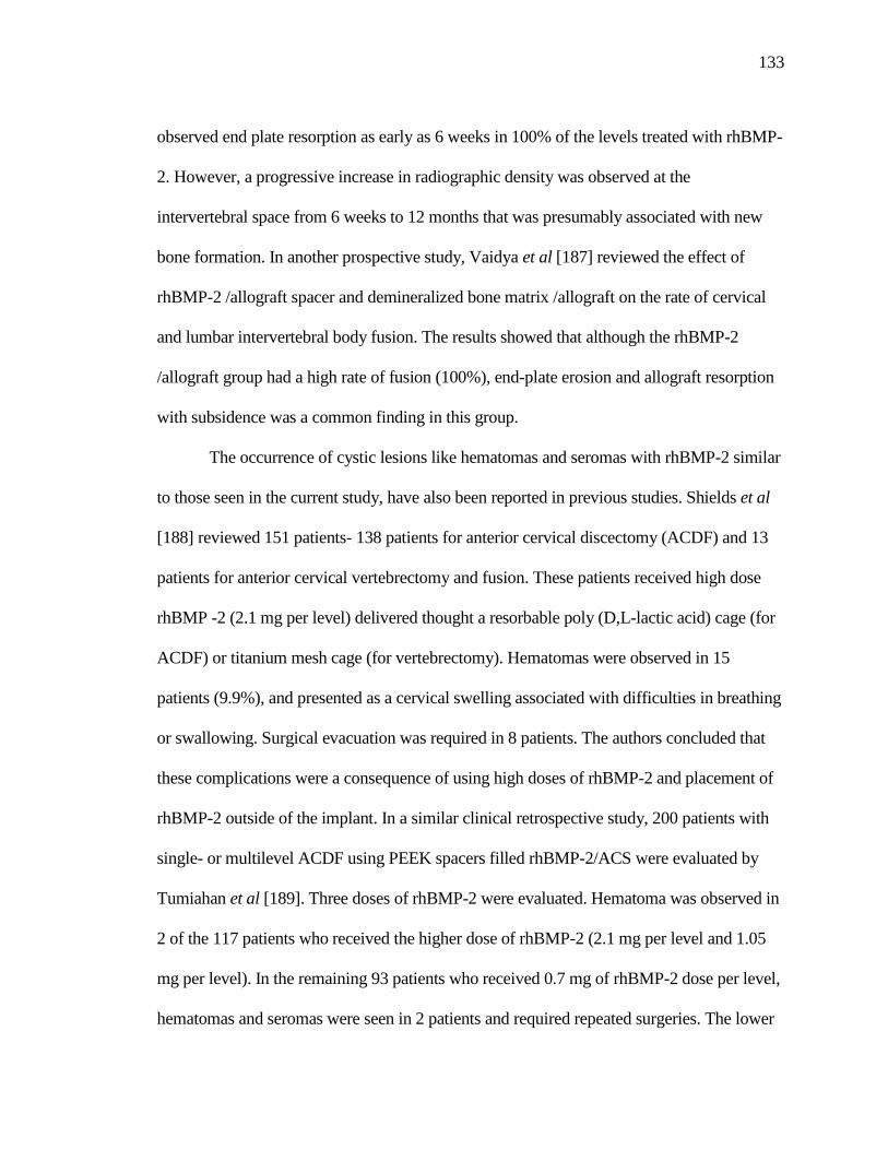
133
observed end plate resorption as early as 6 weeks in 100% of the levels treated with rhBMP-
2. However, a progressive increase in radiographic density was observed at the
intervertebral space from 6 weeks to 12 months that was presumably associated with new
bone formation. In another prospective study, Vaidya et al [187] reviewed the effect of
rhBMP-2 /allograft spacer and demineralized bone matrix /allograft on the rate of cervical
and lumbar intervertebral body fusion. The results showed that although the rhBMP-2
/allograft group had a high rate of fusion (100%), end-plate erosion and allograft resorption
with subsidence was a common finding in this group.
The occurrence of cystic lesions like hematomas and seromas with rhBMP-2 similar
to those seen in the current study, have also been reported in previous studies. Shields et al
[188] reviewed 151 patients- 138 patients for anterior cervical discectomy (ACDF) and 13
patients for anterior cervical vertebrectomy and fusion. These patients received high dose
rhBMP -2 (2.1 mg per level) delivered thought a resorbable poly (D,L-lactic acid) cage (for
ACDF) or titanium mesh cage (for vertebrectomy). Hematomas were observed in 15
patients (9.9%), and presented as a cervical swelling associated with difficulties in breathing
or swallowing. Surgical evacuation was required in 8 patients. The authors concluded that
these complications were a consequence of using high doses of rhBMP-2 and placement of
rhBMP-2 outside of the implant. In a similar clinical retrospective study, 200 patients with
single- or multilevel ACDF using PEEK spacers filled rhBMP-2/ACS were evaluated by
Tumiahan et al [189]. Three doses of rhBMP-2 were evaluated. Hematoma was observed in
2 of the 117 patients who received the higher dose of rhBMP-2 (2.1 mg per level and 1.05
mg per level). In the remaining 93 patients who received 0.7 mg of rhBMP-2 dose per level,
hematomas and seromas were seen in 2 patients and required repeated surgeries. The lower

134
complication rate seen in that study was attributed to the lower dose of rhBMP-2 contained
within a PEEK spacer, without placement of any extraneous sponges anterior to the plate or
lateral to the graft.
Various in vivo animal studies have also demonstrated the relationship between the
doses of rhBMP-2 and the related transient resorptive effects. In one such study, Miyaji et al
examined the effect of two doses of rhBMP-2 on dentin resorption and formation of
cementum-like tissue in an in vivo rat model [190]. Dentin blocks prepared from rat roots
were soaked in 0, 100, or 400 µg/ml rhBMP-2 and implanted into palatal connective tissue
of rats. Histologic and histomorphometric analyses were done at 2, 4 and 8 weeks after
surgery. A significantly greater dentin resorption was observed in the 100 and 400 µg/ml
groups than 0 µg/ml groups. Also, the cementum formation at 8 weeks in the low dose
100 µg/ml (41.8%) group was significantly greater than the 400 µg/ml (16.2%). This was
associated with overdose related inhibitory action of rhBMP-2 for induction of
cementum-like tissue. In one of the most recent studies, Toth et al [165] evaluated the
cellular events related with varying rhBMP-2/ACS concentrations and volumes in the
ovine corticocancellous distal femur defect model. Five treatment groups with increasing
effective concentrations of rhBMP-2/ACS (0x, 1x, 2x, 3.5x and 7x) were formed by
altering the volume of ACS carrier and dose of rhBMP-2 at the site of defect. The
animals were evaluated by both CT scanning, histology and histomorphometry at survival
periods of 1, 4, or 8 weeks postoperatively. The results showed a highly interesting dose
dependent osteoclastic activity and resorption zones adjacent to the original defect and
extending into peri-implant cancellous bone. However, the defects were transient and

135
cessation of osteoclastic activity was observed at 4 weeks with progressive bone healing
in the 8-week rhBMP-2/ACS treatment groups.
Based on the findings from previous studies and their comparison with the current
study, it can be concluded that the use of 0.43 mg/ml rhBMP-2 soaked in ACS carrier with
the pedicle screws was associated with early transient bone resorption in the peri-implant
area. These defects were reduced and replaced by remodeled bony trabeculae, which were
seen as far as 3-10 mm away from the screw. The initially formed de novo bone was
hypodense and osteopenic in relation to the normal trabeculae, however this was
progressively replaced by isodense bone at the later time period in the rhBMP-2/ACS 12
weeks. Thus, with the current carrier and release kinetics, rhBMP-2 on ACS may not be an
ideal carrier for procedures which demand immediate stability, like in case of pedicle screw
instrumentation.
The cysts and transient resorption regions in this study were almost exclusively
found in relation to the fenestrations where the rhBMP-2/ACS was delivered. It can be
speculated that these defects were related to localized hyperconcentration of rhBMP-2. This
might have occurred due to placement of rhBMP-2 both within and around fenestrations and
cannulations; or due to squeezing out of the rhBMP-2 in to the peri-implant area during
surgical placement procedures. Future studies can be directed towards modification of the
placement, concentration and dose of rhBMP-2 and finding alternative carriers with
different handling and release kinetics for induction of peri-implant bone.

136
BIBLIOGRAPHY:
1. Praemer A, Furner S, Rice DP. Musculoskeletal conditions in the United States.
Rosemont, IL. Ed 2. American Academy of Orthopedic Surgeons;1999.
2. Oliver J, Middleditch A. Functional anatomy of the spine. Oxford, England:
Butterworth-Heinemann;1991.
3. Boden SD. Overview of the biology of lumbar spine fusion and principles for selecting
a bone graft substitute. Spine,2002;27(16S):S26-31.
4. Halvorson TL, Kelley LA, Thomas KA, Whitecloud TS 3rd, Cook SD. Effects of bone
mineral density on pedicle screw fixation. Spine,1994;19:2415-20.
5. Weinstein JN, Spratt KF, Spengler D, Brick C, Reid S. Spinal pedicle fixation:
reliability and validity of roentgenogram-based assessment and surgical factors on
successful screw placement. Spine,1988;13:1012-8.
6. Yi X, Wang Y, Lu H, Li C, Zhu T. Augmentation of pedicle screw fixation strength
using an injectable calcium sulfate cement: an in vivo study. Spine,
2008;33(23):2503-9.
7. Derincek A, Wu C, Mehbod A, Transfeldt EE. Biomechanical comparison of anatomic
trajectory pedicle screw versus injectable calcium sulfate graft-augmented pedicle
screw for salvage in cadaveric thoracic bone. Spinal Disord Tech,2006;19:286-91.
8. Pfeifer BA, Krag MH, Johnson C. Repair of failed transpedicle screw fixation: A
biomechanical study comparing polymethylmethacrylate, milled bone, and
matchstick bone reconstruction. Spine,1994;19:350-3.
9. Yilmaz C, Atalay B, Caner H, Altinors N. Augmentation of a loosened sacral pedicle
screw with percutaneous polymethylmethacrylate injection. J Spinal Disord
Tech,2006;19:373-75.
10. Tan JS, Kwon BK, Dvorak MF, Fisher CG, Oxland TR. Pedicle screw motion in the
osteoporotic spine after augmentation with laminar hooks, sublaminar wires, or
calcium phosphate cement: a comparative analysis. Spine,2004;29(16):1723-30.
11. Sanden B, Johansson C, Olerud C, Larsson S. Improved bone screw interface with
hydroxyapatite coating: an in vivo study of loaded pedicle screws in sheep. Spine
2001;26:2673-78.

137
12. Sanden B, Olerud C, Petren-Mallmin M, Larsson S. Hydroxyapatite coating improves
fixation of pedicle screws. A clinical study. J Bone Joint Surg Br,2002;84-B:387-
91.
13. Yildirim OS, Aksakal B, Hanyaloglu SC, Erdogan F, Okur A. Hydroxyapatite dip
coated and uncoated titanium poly-axial pedicle screws: an in vivo bovine model.
Spine,2006;31(8):E215-E220.
14. Boden SD, Andersson GBJ, Anderson DG, Damien C, Ebara S, Helm G, Lane JM,
McKay G, Sandhu HS, Seeherman H, Wozney J. Summary statement: Overview of
bone morphogenetic proteins for spine fusion. Spine,2002;27:16S,S1.
15. United States Food and Drug Administration, Department of Health and Human
Services, Center for Devices and Radiological Health. INFUSE Bone
Graft/LTCAGE Lumbar Tapered Fusion Devices—P000058. July 2, 2002.
www.fda.gov/ cdrh/pdf/P000058.html.
16. Burkus JK, Gornet MF, Dickman CA, Zdeblick TA. Anterior lumbar interbody
fusion using rhBMP-2 with tapered interbody cages. J Spinal Disord
Tech,2002;15:337-49.
17. Sandhu HS, Kabo JM, Turner AS, Liu D, Kanim LEA, Toth JM. North American
Spine Society, 11th Annual Conference, Vancouver, B.C., Canada, Oct 23-26,
1996:47.
18. Sandhu HS, Toth JM, Diwan AD, Seim HB 3rd, Kanim LE, Kabo JM, Turner AS.
Histologic evaluation of the efficacy of rhBMP-2 compared with autograft bone in
sheep spinal anterior interbody fusion. Spine,2002;27:567-75.
19. Boden SD, Martin GJ Jr, Horton WC, Truss TL, Sandhu HS. Laparoscopic anterior
spinal arthrodesis with rhBMP-2 in a titanium interbody threaded cage. J Spinal
Disord,1998;11:95-101.
20. Schimandle JH, Boden SD, Hutton WC. Experimental spinal fusion with recombinant
human bone morphogenetic protein-2. Spine,1995;20:1326-37.
21. Boden SD, Kang J, Sandhu H, Heller JG. Use of recombinant human bone
morphogenetic protein-2 to achieve posterolateral lumbar spine fusion in humans: a
prospective, randomized clinical pilot trial. Spine,2002;27:2662-73.
22. Grey H. Grey’s Anatomy. Ed. T Pick and R Howden. Pennsylvania: Running Press;
1974.

138
23. Xu R, Ebraheim N. ―Surgical Anatomy of the spine‖. Spinal Instrumentation 2nd
edition, Eds: An HS and Colter J, Chapter 2. Philadelphia:Lippincott, Williams &
Wilkins;1999:9-30.
24. Bridwell K. Anatomy lesson: spinal or vertebral column: Available at- The spine
universe.
25. National Institute of Arthritis and Musculoskeletal and Skin Diseases (NIAMS)
Available at http://www.niams.nih.gov/Health_Info/Scoliosos/default.asp
26. Spinal Deformity and Related Conditions:The Burden of Musculoskeletal Diseases in
the United States. Available at- http://www.boneandjointburden.org/pdfs/BMUS
_chpt3_spinal%20deformity.pdf
27. Rodan GA, Reszka AA. Osteoporosis and bisphosphonates. J Bone Joint Surg
Am,2003;85:8-12.
28. Rao RD, Singrakhia MD. Painful osteoporotic vertebral fracture. Pathogenesis,
evaluation, and roles of vertebroplasty and kyphoplasty in its management. J Bone
Joint Surg Am,2003;85:2010-22.
29. Reiter GT. Vertebral fracture. eMedicine Journal [serial online]; 2004. Available at
http://www.emedicine.com/med/TOPIC2895.HTM.
30. Sherman AL, Razack N. Lumbar compression fracture. 2007. Available at
http://emedicine.medscape.com/article/309615-overview.
31. Manson NA, Phillips FM. Minimally invasive techniques for the treatment of
osteoporotic vertebral fractures. J Bone Joint Surg Am,2006;88:1862-72.
32. Riggs BL, Melton LJ 3rd
. The worldwide problem of osteoporosis: insights afforded
by epidemiology. Bone,1995;17(5S):505S-11S.
33. Hu SS, Tribus CB, Diab M, Ghanayem AJ. Spondylolisthesis and spondylolysis. J
Bone Joint Surg Am,2008;90:656-671.
34. Wiltse LL, Newman PH, MacNab I. Classification of spondylolysis and
spondylolisthesis. Clin Orthop Relat Res,1976;117:23-9.
35. Fredrickson BE, Baker D, McHolick WJ, Yuan HA, Lubicky JP. The natural history
of spondylolysis and spondylolisthesis. J Bone Joint Surg Am,1984;66(5):699-707.
36. Marchetti PG, Bartolozzi P. Classification of spondylolisthesis as a guideline for
treatment. In: Bridwell KH, DeWald RL, editors. The textbook of spinal surgery.
2nd
ed. Philadelphia: Lippincott-Raven;1997:1212.

139
37. Leucht P, Fischer K, Muhr G, Mueller EJ. Epidemiology of traumatic spine fractures.
Injury,2009;40(2):166-72.
38. White A, Panjabi MM. Clinical biomechanics of the spine. Philadelphia: Kap. II:J.B.
Lippincott Company;1990.
39. Bucholz RW, Heckman JD, Court-Brown CM. Rockwood & Green's Fractures in
Adults. 6th
edition. Lippincott Williams & Wilkins;2006.
40. Gertzbein S. Scoliosis Research Society. Multicenter spine fracture study.
Spine,1992;17:528-40.
41. Robertson PA. Fractures of L4 and L5 (Low Lumbar Fractures). Available at: The
spine universe.
42. Denis F. The three columns of the spine and its significance in the classification of
acute thoracolumbar spine injuries. Spine,1983;8:817-831.
43. Balloon kyphoplasty for vertebral compression fractures. Published by the National
Institute for Health and Clinical Excellence,2006; ISBN 1-84629-191-7.
44. Benson DR. Unstable thoracolumbar fractures, with emphasis on the burst fracture.
Clin Orthop,1988;230:14-29.
45. National Spinal Cord Injury Statistical Center (NSCISC). Spinal Cord Injury. Facts
and Figures at a Glance. Birmingham,Alabama: NSCISC; April 2009.
46. Verlaan JJ, Diekerhof CH, Buskens E, van der Tweel I, Verbout AJ, Dhert WJ, Oner
FC. Surgical treatment of traumatic fractures of the thoracic and lumbar spine:
Spine,2004;29(7):803-814.
47. Stauffer ES. Internal fixation of fractures of the thoracolumbar spine. J Bone Joint
Surg Am,1984;66:1136-1138.
48. Hadra BE. Wiring the spinous processes in Pott’s disease. Trans Am Orthop Assn,4:
206,1891.
49. Lange F. Support for the spondylitic spine by means of buried steel bars, attached to
the vertebrae. J Bone Joint Surg Am,1910;s2-8:344-361.
50. King D. Internal fixation for lumbosacral fusion. J Bone Joint Surg Am,1948;30:560-
578.
51. Holdsworth FW. Fractures, dislocations and fracture-dislocation of the spine. J Bone
Joint Surg,1963;45B:6-20.
140
52. Harrington PR. Treatment of scoliosis. J Bone Joint Surg Am,1962;44A:591-610.
53. Harrington PR, Dickson JH. An eleven-year clinical investigation of Harrington
instrumentation: a preliminary report on 578 cases. Clin Orthop Rel Res,
1973;93:113-130.
54. Flesch JR , Leider LL, Erickson DL, Chou SN, Bradford DS. Harrington
instrumentation and spine fusion for unstable fractures and fracture-dislocations of
the thoracic and lumbar spine. J Bone Joint Surg Am,1977;59(2):143-153.
55. Jacobs RR, Asher MA, Snider RK. Thoracolumbar spinal injuries: a comparative
study of recumbent and operative treatment in 100 patients. Spine,1982;5:463-477.
56. Luque ER. Surgical immobilization of the spine in elderly patients. Clinical Orthop,
1978;133:273-274.
57. Vaccaro AR, Garfin SR. Internal fixation (pedicle screw fixation) for fusion of the
lumbar spine. Spine,1995;20(24S):157S-165S.
58. Madsen PW. Dorsal approach for treatment of thoracolumbar spine fractures. Tech in
Neurosurg,2003;8(2):101-114.
59. Suk SI, Kim WJ, Lee SM, Kim JH, Chung ER. Thoracic pedicle screw fixation in
spinal deformities: are they really safe? Spine,2001;26(18):2049-2057.
60. Krag MH, Beynnon BD, Pope MH, Frymoyer JW, Haugh LD, Weaver DL. An
internal fixator for posterior application to short segments of the thoracic, lumbar,
or lumbosacral spine: design and testing. Clin Orthop,1986;203:75-98.
61. Benzel EC. Biomechanics of spine stabilization, principles and clinical practice Ed.1.
McGraw-Hill, New York;1995.
62. Toumey J W. Internal fixation in fusion of the lumbosacral joints. Lahey Clin Bull,
1943;3:188-192.
63. Casey MP, Asher MA, Jacobs RR, Orrick JM. The effect of Harrington rod
contouring on lumbar lordosis. Spine,1987;12(8):750-3.
64. Hibbs RA. An operation for progressive spinal deformities. NY Med J,1911;93:1013-
1016.
65. Albee FH. Transplantation of a portion of the tibia into the spine for Pott's disease. A
preliminary report. J Am Med Assoc,1911;57:885-886.

141
66. Kotani Y, Cunningham BW, Cappuccino A, Kaneda K, McAfee PC. The role of
spinal instrumentation in augmenting lumbar posterolateral fusion. Spine,
1996;21(3):278-87.
67. Fraser RD. Interbody, posterior, and combined lumbar fusions. Spine,1995;15;20(24
S):167S-177S.
68. Hoppenfeld S, deBoer P. Surgical exposures in orthopaedics: The anatomic approach.
3rd
edition. Philadelphia: Lippincott Williams and Wilkins;2003.
69. Boucher HH. A method of spinal fusion. J Bone and Joint Surg Br,1959;41B(2):248-
259.
70. Pennel GF, McDonald GA, Dale GG. A method of spine fusion using internal
fixation. Clin Orthop,1964;35:86-94.
71. Harrington PR, Tullos HS. Reduction of severe spondylolisthesis in children.
Southern Med J,1969;62:1-7.
72. Roy-Camille R, Saillant G, Mazel C. Internal fixation of the lumbar spine with
pedicle screw plasting. Clin Orthop,1986;203:7-17.
73. Roy-Camille R, Saillant G, Mazel C. Plating of thoracic, thoracolumbar, and lumbar
injuries with pedicle screw plates. Orthop Clin North Am,1986;17:147-59.
74. Steffee AD, Biscup RS, Sitkowski DJ. Segmental spine plates with pedicle screw
fixation. Clin Orthop,1986;203:45-53.
75. Gaines RW Jr. The use of pedicle-screw internal fixation for the operative treatment
of spinal disorders. J Bone Joint Surg Am,2000;82:1458-76.
76. Available at http://www.burtonreport.com/infspine/SurgStabilPedScrews.htm.
77. Benzel EC. Spine surgery: techniques, complication avoidance, and management,
Volume 2, Churchill Livingstone, New York;2005.
78. Poitout DG. Biomechanics and biomaterials in orthopedics. 1st Ed. Springer, NY;
2004.
79. FDA Final Rule: Pedicle Screw Systems Rule 21 CFR Part 888.3070. 1998.
Available at http//www.fda.org
80. Yilmaz C, Atalay B, Caner H, Altinors N. Augmentation of a loosened sacral pedicle
screw with percutaneous polymethylmethacrylate injection. J Spinal Disord
Tech,2006;19:373-375.

142
81. Grubb SA, Lipscomb HJ. Results of lumbosacral fusion for degenerative disc disease
with and without instrumentation. Two- to five-year follow-up. Spine,1992:17:349-
355.
82. Ransom N, La Rocca SH, Thalgott J. The case for pedicle fixation of the lumbar
spine. Spine,1994;19(23):2702-6.
83. Barr SJ, Schuette AM, Emans JB. Lumbar pedicle screws versus hooks. Results in
double major curves in adolescent idiopathic scoliosis. Spine,1997;22:1369-1379.
84. Dai LD. Low lumbar spinal fractures: management options. Injury,2002;33(7):579-
82.
85. Mac Millan, MM, Cooper R, Haid R. Lumbar and lumbosacral fusions using Cotrel-
Dubousset pedicle screws and rods. Spine,1994;19:430-434.
86. West JL III, Bradford DS, Ogilvie JW. Results of spinal arthrodesis with pedicle
screw-plate fixation. J Bone and Joint Surg Am,1991;73-A:1179-1184.
87. Rodgers WB, Williams MS, Schwend RM, Emans JB. Spinal deformity in
myelodysplasia. Correction with posterior pedicle screw instrumentation. Spine,
1997;22:2435-43.
88. Van Royen BJ, de Kleuver M, Slot GH. Polysegmental lumbar posterior wedge
osteotomies for correction of kyphosis in ankylosing spondylitis. Eur Spine
J,1998,7:104-110.
89. Lehmer SM, Keppler L, Biscup RS, Enker P, Miller SD, Steffee AD. Posterior
transvertebral osteotomy for adult thoracolumbar kyphosis. Spine,1994;19:2060-
2067.
90. Jonsson B, Sjostrom L, Olerud C, Andreasson I, Bring J, Rauschning W. Outcome
after limited posterior surgery for thoracic and lumbar spine metastases. Eur Spine
J,1996;5:36-44.
91. Brown CA, Lenke LG, Bridwell KH, Geideman WM, Hasan SA, Blanke K.
Complications of pediatric thoracolumbar and lumbar pedicle screws. Spine,
1998;23:1566-1571.
92. Lonstein JE, Denis F, Perra JH, Pinto MR, Smith MD, Winter RB. Complications
associated with pedicle screws. J Bone Joint Surg Am,1999;81(11):1519-28.
93. Pihlajämaki H, Myllynen P, Böstman O. Complications of transpedicular lumbosacral
fixation for non-traumatic disorders. J Bone Joint Surg Br,1997;79-B:183-9.

143
94. Liljenqvist UR, Halm HF, Link TM. Pedicle screw instrumentation of the thoracic
spine in idiopathic scoliosis. Spine,1997;22:2239-45.
95. Blumenthal S, Gill K. Complications of the Wiltse pedicle screw fixation system.
Spine,1993;18:1867-71.
96. Faraj AA, Webb JK. Early complications of spinal pedicle screw. Eur Spine J,
1997;6:324-326.
97. Matsuzaki H, Tokuhashi Y, Matsumoto F, Hoshino M, Kiuchi T, Toriyama S.
Problems and solutions of pedicle screw plate fixation of lumbar spine.
Spine,1990;15:1159-65.
98. Davne SH, Myers DL. Complications of lumbar spinal fusion with transpedicular
instrumentation. Spine,1992;17(6S):S184-9.
99. Masferrer R, Gomez CH, Karahalios DG, Sonntag VK. Efficacy of pedicle screw
fixation in the treatment of spinal instability and failed back surgery: a 5-year
review. J Neurosurg,1998;89(3):371-7.
100. West JL, Ogilvie JW, Bradford DS. Complications of the variable screw plate
pedicle screw fixation. Spine,1991;16(5):576-9.
101. Hsu J, Zuckerman JF, White AH, Wynne G. Internal fixation with pedicle screws.
In: White AH, Rothman RH, Roy CD, eds. Lumbar Spine Surgery.CV Mosby, St
Louis;1987:322-38.
102. Essens SI, Sachs BL, Dreyzin V. Complications associated with the technique of
pedicle screw fixation: A selected survey of ABC members.
Spine,1993;18(15):2231-2239.
103. Hirano T, Hasegawa K, Washio T, Hara T, Takahashi H. Fracture risk during
pedicle screw insertion in osteoporotic spine. J Spinal Disord,1998;11(6):493-7.
104. Gurr KR, McAfee PC. Cotrel-Dubousset instrumentation in adults. A preliminary
report. Spine,1988;13:510-20.
105. Tan JS, Singh S, Zhu QA, Dvorak MF, Fisher CG, Oxland TR. The effect of cement
augmentation and extension of posterior instrumentation on stabilization and
adjacent level effects in the elderly spine. Spine,2008;33(25):2728-40.
106. Okuyama K, Sato K, Abe E, Inaba H, Shimada Y, Murai H. Stability of transpedicle
screwing for the osteoporotic spine: in vitro study of the mechanical stability. Spine
1993;18:2240-5.

144
107. Upasani VV, Farnsworth CL, Tomlinson T, Chambers RC, Tsutsui S, Slivka MA,
Mahar AT, Newton PO. Pedicle screw surface coatings improve fixation in
nonfusion spinal constructs. Spine,2009;34(4):335-343.
108. McLachlin SD, Beaton BJ, Sabo MT, Gurr KR, Bailey SI, Bailey CS, Dunning CE.
Comparing the fixation of a novel hollow screw versus a conventional solid screw
in human sacra under cyclic loading. Spine,2008;33:1870-1875.
109. Cook SD, Salkeld SL, Whitecloud TS 3rd
, Barbera J. Biomechanical evaluation and
preliminary clinical experience with an expansive pedicle screw design. J Spinal
Disord,2000;13(3):230-236.
110. Chapman JR, Harrington RM, Lee KM, Anderson PA, Tencer AF, Kowalski D.
Factors affecting the pullout strength of cancellous bone screws. J Biomech Eng,
1996;118:391-8.
111. Polly DW Jr, Orchowski JR, Ellenbogen RG. Revision pedicle screws. Bigger,
longer shims-what is best? Spine,1998;23:1374-9.
112. Skinner R, Maybee J, Transfeldt E, Venter R, Chalmers W. Experimental pullout
testing and comparison of variables in transpedicular screw fixation: a
biomechanical study. Spine,1990;15:195-201.
113. Schramm M, Krummbein S, Kraus H, Pitto RP, Schmidt R. Anterior vertebral body
screw pullout testing with the hollow modular anchorage system- a comparative in
vitro study. Biomed Technik (Berl),2003;48:356-61.
114. Lehman RA Jr, Polly DW Jr, Kuklo TR, Cunningham B, Kirk KL, Belmont PJ Jr.
Straight-forward versus anatomic trajectory technique of thoracic pedicle screw
fixation: a biomechanical analysis. Spine,2003;28:2058-65.
115. Zindrick MR, Wiltse LL, Widell EH, Thomas JC, Holland WR, Field BT, Spencer
CW. A biomechanical study of intrapedicular screw fixation in the lumbosacral
spine. Clin Orthop Relat Res,1986;203:99-112.
116. Hilibrand AS, Moore DC, Graziano GP. The role of pediculolaminar fixation in
compromised pedicle bone. Spine,1996;21:445-51.
117. McKoy BE, An YH. An expandable anchor for fixation in osteoporotic bone. J
Orthop Res,2001;19:545-7.
118. McKoy BE, Connor GS, An YH. An interlocking screw for fixation in osteoporotic
bone. Presented at: 47th Annual Meeting of Orthopaedic Research Society;
2001:109.

145
119. Wilkes RA, Mackinnon JG, Thomas WG. Neurological deterioration after cement
injection into a vertebral body. J Bone Joint Surg Br,1994;76:155-63.
120. Xue W, Liu X, Zheng X, Ding C. In vivo evaluation of plasma-sprayed titanium
coating after alkali modification. Biomaterials,2005;26:3029-37.
121. Termaat MF, Den Boer FC, Bakker FC, Patka P, Haarman HJ . Bone morphogenetic
proteins. Development and clinical efficacy in the treatment of fractures and bone
defects. J Bone Joint Surg Am,2005;87:1367-78.
122. Kingsley DM. The TGF-beta superfamily: new members, new receptors, and new
genetic tests of function in different organisms. Genes Dev,1994;8:133-46.
123. Lan J, Wang Z F, Shi B, Xia HB, Cheng XR. The influence of recombinant human
BMP-2 on bone-implant osseointegration: biomechanical testing and
histomorphometric analysis. Int J Oral Maxillofac Surg,2007;36:345-349.
124. Senn N. On the healing of aseptic bone cavities by implantation of antiseptic
decalcified bone. Am J Med Sci,1889;98:219-243.
125. Lacroix P. Recent investigation on the growth of bone. Nature,1945;156:576.
126. Urist MR. Bone: formation by autoinduction. Science,1965;150:893-899.
127. Reddi AH, Huggins C. Biochemical sequences in the transformation of normal
fibroblasts in adolescent rats. Proc Natl Acad Sci USA,1972;69:1601-5.
128. Wozney JM, Rosen V, Celeste AJ, Mitsock LM, Whitters MJ, Kriz RW, Hewick
RM, Wang EA. Novel regulators of bone formation: molecular clones and
activities. Science,1988;242:1528-34.
129. Wozney JM, Rosen V, Byrne M, Celeste AJ, Moutsatsos I, Wang EA. Growth
factors influencing bone development. J Cell Sci Suppl,1990;13:149-56.
130. Reddi AH. Bone Morphogenetic Proteins: From basic science to clinical
applications. J Bone Joint Surg Am,2001;83:1-6.
131. Lieberman JR, Daluiski A, Einhorn TA. The role of growth factors in the repair of
bone. Biology and clinical applications. J Bone Joint Surg Am,2002;84:1032-1044.
132. Wozney JM. Overview of bone morphogenetic proteins. Spine,2002;27:S2-S8.
133. Yamaguchi A, Katagiri T, Ikeda T, Wozney JM, Rosen V, Wang EA, Kahn AJ,
Suda T, Yoshiki S. Recombinant human bone morphogenetic protein-2 stimulates

146
osteoblastic maturation and inhibits myogenic differentiation in vitro. J Cell Biol,
1991;113:681-687.
134. Rihn JA, Gates C, Glassman SD, Phillips FM, Schwender JD, Albert TJ. The use of
bone morphogenetic protein in lumbar spine surgery. J Bone Joint Surg Am,
2008;90:2014-2025.
135. Schmitt JM, Hwang K, Winn SR, Hollinger JO. Bone morphogenetic proteins: an
update on basic biology and clinical relevance. J Orthop Res,1999;17:269-78.
136. Mont MA, Ragland PS, Biggins B, Friedlaender G, Patel T, Cook S, Etienne G,
Shimmin A, Kildey R, Rueger DC, Einhorn TA. Use of bone morphogenetic
proteins for musculoskeletal applications. An overview. J Bone Joint Surg Am,
2004;86:41-55.
137. rhBMP-2/ACS. Understanding the mechanism of action. Medtronic Sofamor Danek.
Available at www.bmp2.com.br/pdf/infusemoa.pdf
138. Ramirez BP, Steckert JJ.. Therapeutic proteins- Methods & Protocols. in Analytical
ultracentrifugation. Ed by Smales MC, James DC. Humana Press Inc ,Totowa,
NJ;2005.
139. Kokubo S, Nozaki K, Fukushima S, Takahashi K, Miyata K, Fujimoto R, Yokota S.
Recombinant human bone morphogenetic protein-2 as an osteoinductive
biomaterial and a biodegradable carrier in a rabbit ulnar defect model. J Bioactive
and Compatible Polymers,2008;23;348-366.
140.Yamaguchi A, Ishizuya T, Kintou N, Wada Y, Katagiri T, Wozney JM. Effects of
BMP-2, BMP-4, and BMP-6 on osteoblastic differentiation of bone marrow-derived
cell Lines, ST2 and MC3T3-G2/ PA6, Biochem Biophys Res Commun,
1996;220:366-371.
141. Katagiri T, Yamaguchi A, Komaki M, Abe E, Takahashi N, Ikeda T, Rosen V,
Wozney JM, Fujisawa-Sehara A, Suda T. Bone morphogenetic protein-2 converts
the differentiation pathway of C2C12 myoblasts into the osteoblast lineage, J Cell
Biol,1994;127:1755-66.
142. Deckers MM, van Bezooijen RL, van der Horst G, Hoogendam J, van Der Bent C,
Papapoulos SE, and Löwik CW. Bone morphogenetic proteins stimulate
angiogenesis through osteoblast-derived vascular endothelial growth factor A.
Endocrinology,2002;143(4):1545-53.
143. Ebara S, Nakayama K. Mechanism for the action of bone morphogenetic proteins
and regulation of their activity. Spine,2002;27(16S):S10-S15.

147
144. Kanatani M, Sugimoto T, Kaji H, Kobayashi T, Nishiyama K, Fukase M,
Kumegawa M, Chihara K. Stimulatory effect of bone morphogenetic protein-2 on
osteoclast-like cell formation and bone-resorbing activity. J Bone Miner
Res,1995;10:1681-90.
145. Koide M, Murase Y, Yamato K, Noguchi T, Okahashi N, Nishihara T. Bone
morphogenetic protein-2 enhances osteoclast formation mediated by interleukin-
alpha through upregulation of osteoclast differentiation factor and cyclooxygenase-
2. Biochem Biophys Res Commun,1999;259:97-102.
146. Itoh K, Udagawa N, Katagiri T, Iemura S, Ueno N, Yasuda H, Higashio K, Quinn
JM, Gillespie MT, Martin TJ, Suda T, Takahashi N. Bone morphogenetic protein 2
stimulates osteoclast differentiation and survival supported by receptor activator of
nuclear factor-kappaB ligand. Endocrinology,2001;142:3656-62.
147. Uludag H, Gao T, Porter TJ, Friess W, Wozney JM. Delivery systems for BMPs:
factors contributing to protein retention at an application site. J Bone Joint Surg
Am,2001;83:128-135.
148. Uludag H, D'Augusta D, Palmer R, Timony G, Wozney J. Characterization of
rhBMP-2 pharmacokinetics implanted with biomaterial carriers in the rat ectopic
model. J Biomed Mater Res,1999;46:193-202.
149. Maus U, Andereya S, Gravius S, Ohnsorge JA, Niedhart C, Siebert CH. BMP-2
incorporated in a tricalcium phosphate bone substitute enhances bone remodeling in
sheep. J Biomater Appl,2008;22(6):559-76.
150. Khan SN, Fraser JF, Sandhu HS, Cammisa FP Jr, Girardi FP, Lane JM. Use of
osteopromotive growth factors, demineralized bone matrix, and ceramics to
enhance spinal fusion. J Am Acad Orthop Surg,2005;13:129-37.
151. Sampath TK, Reddi AH. Homology of bone inductive proteins from human,
monkey, bovine, and rat extracellular matrix. Proc Natl Acad Sci
USA,1983;80:6591-5.
152. Friess W, Uludag H, Foskett S, Biron R, Sargeant C. Characterization of absorbable
collagen sponges as rhBMP-2 carriers. Int J Pharm,1999;187(1):91-9.
153. Shi S, Cheng X, Wang J, Zhang W, Peng L, Zhang Y.RhBMP-2 microspheres-
loaded chitosan/collagen scaffold enhanced osseointegration: an experiment in dog.
J Biomater Appl,2009;23(4):331-46.
154. Vehof, JWM, Spauwen PHM, Jansen JA. Bone formation in calcium-phosphate-
coated titanium mesh. Biomaterials,2000;21:2003-09.

148
155. Vehof JW, Takita H, Kuboki Y, Spauwen PH, Jansen JA. Histological
characterization of the early stages of bone morphogenetic protein-induced
osteogenesis. J Biomed Mater Res,2002;61(3):440-9.
156. Sandhu HS, Boden SD, An H, Kang J, Weinstein J. BMPs and gene therapy for
spinal fusion: Summary statement. Spine,2003;28:S85.
157. Jeon O, Song SJ, Yang HS, Bhang SH, Kang SW, Sung MA, Lee JH, Kim BS.
Long-term delivery enhances in vivo osteogenic efficacy of BMP-2 compared to
short-term delivery. Biochem Biophys Res Commun,2008;369:774-780.
158. Martin GJ Jr, Boden SD, Marone MA, Marone MA, Moskovitz PA. Posterolateral
intertransverse process spinal arthrodesis with rhBMP-2 in a nonhuman primate:
important lessons learned regarding dose, carrier, and safety. J Spinal
Disord,1999;12:179-86.
159. Boden SD, Martin GJ Jr, Horton WC, Truss TL, Sandhu HS. Laparoscopic anterior
spinal arthrodesis with rhBMP-2 in a titanium interbody threaded cage. J Spinal
Disord,1998;11:95-101.
160. David SM, Gruber HE, Meyer RA, Murakami T, Tabor OB, Howard BA, Wozney
JM, Henley EM. Lumbar spinal fusion using recombinant human bone
morphogenetic protein in the canine:A comparison of three dosages and two
carriers. Spine,1999;24(19):1973-79.
161. McClellan JW, Mulconrey DS, Forbes RJ, Fullmer N. Vertebral bone resorption
after transforaminal lumbar interbody fusion with bone morphogenetic protein
(rhBMP-2). J Spinal Disord Tech,2006;19:483-486.
162. Hansen SM, Sasso RC. Resorptive response of rhBMP2 simulating infection in
ananterior lumbar interbody fusion with a femoral ring. J Spinal Disord Tech,
2006;19(2):130-134.
163. Pradhan BB, Bae HW, Dawson EG, Patel VV, Delamarter RB. Graft resorption with
the use of bone morphogenetic protein: lessons from anterior lumbar interbody
fusion using femoral ring allografts and recombinant human bone morphogenetic
protein-2. Spine,2006;31(10):E277-E284.
164. Poynton AR, Lane JM. Safety profile for the clinical use of bone morphogenetic
proteins in the spine. Spine,2002;27(16S):S40-S48.
165. Toth JM, Boden SD, Burkus JK, Badura JM, Peckham SM, McKay WF. Short-term
osteoclastic activity induced by locally high concentrations of recombinant human
bone morphogenetic protein-2 in a cancellous bone environment.
Spine,2009;34(6):539-550.

149
166. United States Food and Drug Administration, Department of Health and Human
Services, Center for Devices and Radiological Health. INFUSE Bone Graft—
P000054. April 30, 2004. www.fda.gov/cdrh/pdf4/P000054.html.
167. United States Food and Drug Administration, Department of Health and Human
Services, Center for Devices and Radiological Health. INFUSE Bone Graft—
P050053. March 9, 2007. www.fda.gov/ cdrh/pdf/ P050053.html.
168. Wilke HJ, Kettler A, Wenger KH, Claes LE. Anatomy of the sheep spine and its
comparison to the human spine. Anat Rec,1997,247:542-55.
169. Egermann M, Goldhahn J, Holz R, Schneider E, Lill CA. A sheep model for fracture
treatment in osteoporosis: benefits of the model versus animal welfare. Lab Anim,
2008;42:453-464.
170. Newman E, Turner AS, Wark JD. The potential of sheep for the study of osteopenia:
current status and comparison with other animal models. Bone,1995;16(4):277S-
284S.
171. Wilke HJ, Kettler A, Claes LE. Are sheep spines a valid biomechanical model for
human spines? Spine,1997;22(20):2365-74.
172. Turner AS, Alvis M, Myers W, Stevens ML, Lundy MW. Changes in bone mineral
density and bone-specific alkaline phosphatase in ovariectomized ewes.
Bone,1995;17:395S-402S.
173. Hornby SB, Ford SL, Mase CA, Evans GP. Skeletal changes in the ovariectomised
ewe and subsequent response to treatment with 17 beta oestradiol.
Bone,1995;17:389S-94S.
174. Turner AS. The sheep as a model for osteoporosis in humans. Vet J, 2002;163:232-
239.
175. Lill CA, Fluegel AK, Schneider E. Effect of ovariectomy, malnutrition and
glucocorticoid application on bone properties in sheep: a pilot study. Osteopor Int,
2002a;13:480-6.
176. Goldhahn J, Jenet A, Schneider E, Lill CA. Slow rebound of cancellous bone after
mainly steroid-induced osteoporosis in ovariectomized sheep. J Orthop Trauma,
2005;19(1):23-8.
177. Sandén B, Olerud C, Larsson S. Hydroxyapatite coating enhances fixation of loaded
pedicle screws: a mechanical in vivo study in sheep. Eur Spine J, 2001;10(4):334-9.

150
178. Sandén B, Olerud C, Petrén-Mallmin M, Johansson C, Larsson S. The significance
of radiolucent zones surrounding pedicle screws. Definition of screw loosening in
spinal instrumentation. J Bone Joint Surg Br,2004;86(3):457-61.
179. Suzuki T, Abe E, Okuyama K, Sato K. Improving the pullout strength of pedicle
screws by screw coupling. J Spinal Disord,2001;14(5):399-403.
180. Klein SA, Glassman SD, Dimar JR 2nd
, Voor MJ. Evaluation of the fixation and
strength of a "rescue" revision pedicle screw. J Spinal Disord Tech,2002;15(2):100-
4.
181. Milcan A, Ayan I, Zeren A, Sinmazcelik T, Yilmaz A, Zeren M, Kuyurtar F.
Evaluation of cyanoacrylate augmentation of transpedicular screw pullout strength.
J Spinal Disord Tech,2005;18(6):511-4.
182. Hecht BP, Fischgrund JS, Herkowitz HN, Penman L, Toth JM, Shirkhoda A. The
use of recombinant human bone morphogenetic protein 2 (rhBMP-2) to promote
spinal fusion in a nonhuman primate anterior interbody fusion model.
Spine,1999;24(7):629-36.
183. Martin GJ Jr, Boden SD, Titus L Recombinant human bone morphogenetic protein-
2 overcomes the inhibitory effect of ketorolac, a nonsteroidal anti-inflammatory
drug (NSAID), on posterolateral lumbar intertransverse process spine fusion. Spine,
1999;24(21):2188-94.
184. Sucato DJ, Hedequist D, Zhang H, Pierce WA, O'Brien SE, Welch RD.
Recombinant human bone morphogenetic protein-2 enhances anterior spinal fusion
in a thoracoscopically instrumented animal model. J Bone Joint Surg Am,
2004;86A(4):752-762.
185. Meyer RA Jr, Gruber HE, Howard BA, Tabor OB Jr, Murakami T, Kwiatkowski
TC, Wozney JM, Hanley EN Jr. Safety of recombinant human bone morphogenetic
protein-2 after spinal laminectomy in the dog. Spine,1999;24(8):747-54.
186. Vaidya R, Carp J, Sethi A, Bartol S, Craig J, Les CM. Complications of anterior
cervical discectomy and fusion using recombinant human bone morphogenetic
protein-2. Eur Spine J,2007;16(8):1257-65.
187. Vaidya R, Weir R, Sethi A, Meisterling S, Hakeos W, Wybo CD. Interbody fusion
with allograft and rhBMP-2 leads to consistent fusion but early subsidence. J Bone
Joint Surg Br,2007;89:342-345.
188. Shields LB, Raque GH, Glassman SD, Campbell M, Vitaz T, Harpring J, Shields
CB. Adverse effects associated with high-dose recombinant human bone

151
morphogenetic protein-2 use in anterior cervical spine fusion. Spine,
2006;31(5):542-7.
189. Tumialán LM, Pan J, Rodts GE, Mummaneni PV. The safety and efficacy of
anterior cervical discectomy and fusion with polyetheretherketone spacer and
recombinant human bone morphogenetic protein–2: a review of 200 patients. J
Neurosurg Spine,2008;8(6):529-35.
190. Miyaji H, Sugaya T, Kato K, Kawamura N, Tsuji H, Kawanami M. Dentin
resorption and cementum-like tissue formation by bone morphogenetic protein
application. J Periodontal Res,2006;41(4):311-5.

152
APPENDIX A
Approval letter for exemption from the Institutional Animal Care and Use
Committee (IACUC), Marquette University, Milwaukee, WI
RE: Information regarding documentation for IACUC
McDonough, Elizabeth
Sent: Monday, September 08, 2008 4:53 PM
To: Jeffrey M. Toth - MCW [jtoth mcw.edu] ; Arora, Akshi
Cc: Piacsek, Bela
Hello Dr. Toth and Dr. Arora,
Thanks for your patience in this matter. The IACUC discussed this case and has
determined that the project is not subject to IACUC review. The decision is based on
the following: because the animals are not killed specifically for your research, because
the animals are dead when the tissue is harvested, because you will not receive a whole
USDA-regulated animal, and because no killing or pre-killing procedures are modified to
accommodate the conditions of your studies. The IACUC did recommend that you verify
that the tissue comes from Q fever negative animals.
A few changes were proposed to the drafted policy, discussed at the meeting. When the
final version is approved by the IACUC, it will be posted on the ORC website. Until
then, for additional inquiries it may be helpful to include the following information:
1. What kind of tissue will be used?
2. What is the source of the tissue (name of the academic
institution/slaughterhouse)

153
3. Will animals be killed/ slaughtered regardless of the study/need for tissue?
4. Are the animals alive or dead when the tissue is harvested?
5. Will you receive a whole USDA-regulated animal?
6. Will the killing/slaughtering procedure be modified to accommodate the
conditions of your studies?
Thank you for your patience. Please don’t hesitate to contact me with any questions or
comments.
Beth
Elizabeth M. McDonough
Director of Research Compliance
Office of Research Compliance
Marquette University
Schroeder Complex, Room 102
560 N. 16th Street
P.O. Box 1881
Milwaukee, WI 53201-1881
Phone: (414) 288-1479 Fax: (414) 288-6281
URL: http://www.marquette.edu/researchcompliance
Date: Sun, 31 Aug 2008 07:14:16 -0500
From: Arora, Akshi <[email protected]>

154
To: McDonough, Elizabeth <[email protected]>
CC: Toth, Jeffrey <[email protected]>
Dear Madam,
I am a graduate student at Marquette University, and would be starting work on my
Master’s thesis with Dr. Jeffrey Toth. The study that I would be working on is entitled
"Effects of Biologics on Pedicle Screw Fixation in a Sheep Model: Histologic &
Biomechanical Analysis". The study will not involve live animals. I was wondering if I
need to complete any paperwork with the IACUC.
Thanks a lot for your time and efforts, I appreciate it.
Best Regards,
Dr. Akshi Arora

155
APPENDIX B
A list of animal number, vertebral level and orientation of pedicle screw for
biomechanical testing and undecalcified histology
Animal # Level Pull-out Section Orientation Histology Section
Orientation
R155 L2 L R axial
R155 L3 L R longitudinal
R155 L4 R L longitudinal
R155 L5 L R axial
R156 L2 R axial L longitudinal
R156 L3 L R axial
R156 L4 R L axial
R156 L5 L R longitudinal
R157 L2 R L axial
R157 L3 L R longitudinal
R157 L4 L R axial
R157 L5 R L longitudinal
R160 L2 L axial R longitudinal
R160 L3 L longitudinal R axial
R160 L4 R axial L longitudinal
R160 L5 L longitudinal R axial
R161 L2 R L axial
R161 L3 R L longitudinal
R161 L4 L R longitudinal
R161 L5 L R axial
R162 L2 L R longitudinal
R162 L3 R longitudinal L axial
R162 L4 R longitudinal L axial
R162 L5 L axial R longitudinal
R163 L2 L R axial
R163 L3 L R longitudinal
R163 L4 R L longitudinal
R163 L5 R L axial
R165 L2 L R longitudinal
R165 L3 R L axial
R165 L4 R L axial
R165 L5 R L longitudinal

156
APPENDIX C
Schedule for processing vertebral bodies and embedding them in Methyl
Methacrylate
Protocol title: MSB BMP Pedicle Screw Study
Sheep Spines Numbered: R155, R156, R157, R160, R161, R162, R163, R165
(AXIAL & LONGITUDINAL)
Fixative: 10% neutral buffered formalin
Date Solution Function Time Temperature
10 % neutral buffered formalin Fixation PRN 22C
Rinse out fixative in tap water Rinsing 2 hours 22C
70 % ETOH
Graded
dehydration
of the tissue
sample
3-6 days Ambient
80 % ETOH 2 days Ambient
95 % ETOH 3-4 days Ambient
100 % ETOH 3-4 days Ambient
Xylene Clearing 3-4 days Ambient
Osteobed Solution I
Infiltration
7 days 4C
Osteobed Solution II 7 days 4C
Osteobed Solution III 4C