effects of elevated metro rail tracks on pollutant
TRANSCRIPT

International Journal of Applied Environmental Sciences
ISSN 0973-6077 Volume 11, Number 2 (2016), pp. 425-439
© Research India Publications
http://www.ripublication.com
Effects of Elevated Metro Rail Tracks on Pollutant
Dispersion in Urban Street Canyons
Abhishek Pratap Singh
Research Scholar, Department of Mechanical Engineering, The NorthCap University, Gurgaon
Correspondence Author
Pramod Bhatia
Associate Professor, Department of Mechanical Engineering, The NorthCap University, Gurgaon, Haryana, India.
K K Chaudhary
Professor (retired), IIT Delhi, India.
Abstract
Objectives of this study are to analyze the effects of elevated metro rail tracks
(EMRT) on pollutant dispersion phenomena in an urban street canyon. Street
canyon of aspect ratio 1 (regular street canyon) and aspect ratio 0.5 (wide
street canyon) were simulated using two dimensional geometry. Wind flow
has been simulated using k-Ɛ turbulence model. Pollutant dispersion
simulation using Standard, RNG and Realizable k-Ɛ turbulence models were
also compared. CFD technique has been used to simulate the wind flow and
pollutant dispersion modeling. ANSYS FLUENT software were used to
simulate the street canyon cases. Two dimensional geometrical models have
been taken. Transport species model has been used to simulate air-acetylene
mixture dispersion as pollutants. Results of velocity vectors, contours of
pollutant concentration and pollutant concentration plots have been discussed
and compared. Simulation results of different turbulence models were also
compared. Results show that by introduction of EMRT in street canyon of
aspect ratio 1, pollutant concentrations have been increased on both leeward
and windward sides. There were no such significant changes in dispersion
phenomena and pollutant concentrations on street canyon of aspect ratio 0.5
when a cross section of EMRT was introduced. Standard k-Ɛ turbulence
model has predicted similar results to the previous experimental results.
Keywords: Street canyon; pollutant concentration; k-Ɛ turbulence model; air
pollution modeling.

426 Abhishek Pratap Singh et al
1. Introduction A quality transport system is one of the current requirements of highly populated
cities of the world. Metro trains are one of the solutions to develop an effective and
comfortable transportation system. Elevated Metro Rail Tracks (EMRT) are
constructed to operate metro trains. These tracks mostly constructed along the urban
street canyons. This further changes the geometrical configuration of the urban street
canyon. The geometrical configurations are one of the major parameters that affect
pollutant dispersion in street canyons. Comfortable life style, opportunities in jobs,
and quality of education & medical facilities are the major attractions to shift
population from rural to urban areas. This further increase pressures on development
authorities of the cities to provide residential, commercial, and transport
infrastructures. Population growth is also responsible in increasing the number of
vehicles which leads to high emission of pollutants. Vehicle emission represents the
main group of pollutants in urban areas [1]. High pollution levels have been often
observed in urban street canyons due to the increased traffic emission and reduced
natural ventilations [2]. Research area of investigation in this field is to find out
dispersion phenomena of pollutants in street canyons under different conditions.
There are number of parameters which affect dispersion phenomena i.e. wind
orientation, building geometrical configuration, pollutant emission rate, traffic
volume, and road obstacles. Building geometrical configuration plays major role in
dispersion phenomena. Some of the geometrical parameters are, building aspect ratio
(average building height to road width ratio), building configuration, elevated road,
uneven building layouts, roof designs, etc. The street canyon configuration has
significant influence on the pollutant dispersion [3]. Numbers of studies have reported
the influence of street canyon’s geometrical parameters on pollutant dispersion
phenomena [1, 3-10]. Effects on pollutant dispersion in street canyon due to inside
obstacles such as traffic volume and tree planting have also been discussed in
previous studies [10, 11-14]. The Navier stokes and transport species equations
govern the dispersion mechanism of pollutant in street canyon. Mathematical model
calculate pollutant concentration by solving analytically simplified parametric
equations [2]. CFD technique is the best tool to predict the fluid flow and mixing
behavior of pollutants. The major advantages of CFD techniques are low cost
analysis, time saving, and reliability in accuracy of results. In the present study two
dimensional fluid domains have been analyzed for numerical simulation. Numbers of
studies have reported the analysis of 2 dimensional street canyon fluid domains [3, 10,
15-17]. Geometrical fluid models have been modeled using geometry tool of ANSYS
Workbench. Mesh has been generated using meshing tool of ANSYS Workbench.
Appropriate boundary types have been defined. Appropriate physics of the analysis
have been applied on ANSYS FLUENT tool for simulation of different cases. Results
of velocity vectors, pollutant contours, and pollutant concentration profile have been
discussed.
Effects of Elevated Metro Rail Tracks on Pollutant Dispersion 427
2. Numerical Setup and Solution 2.1. Numerical Cases
The two dimensional geometrical analysis has been done in the present study. Four
geometrical cases have been considered. First two cases have been considered on the
basis of aspect ratio of street canyon. Two aspect ratios, namely, 1 and 0.5 have been
used. For each aspect ratio, two geometrical conditions have been introduced. First,
street canyon without elevated metro rail track (EMRT) and second, street canyon
with elevated metro rail track. CFD simulations of pollutant dispersion have been
analyzed using k-Ɛ Turbulent Model and species transport model. All three sub
models of k-Ɛ Turbulent Model i.e. Standard, RNG and Realizable have been used in
all geometrical cases. ANSYS 12.1, FLUENT software has been used for simulations.
All the cases have been listed in Table 1 below.
Table 1. List of numerical cases
Two Dimensional
Street Canyon
Street Canyon of
Aspect Ratio-1
Street canyon
without EMRT
Standard K-Ɛ turbulence
model
RNG K-Ɛ turbulence
model
Realizable K-Ɛ turbulence
model
Street canon
with EMRT
Standard K-Ɛ turbulence
model
RNG K-Ɛ turbulence
model
Realizable K-Ɛ turbulence
model
Street Canyon of
Aspect Ratio – 0.5
Street canyon
without EMRT
Standard K-Ɛ turbulence
model
RNG K-Ɛ turbulence
model
Realizable K-Ɛ turbulence
model
Street canon
with EMRT
Standard K-Ɛ turbulence
model
RNG K-Ɛ turbulence
model
Realizable K-Ɛ turbulence
model
2.2. Geometrical modeling
In the present study, two dimensional geometrical fluid domains have been created
using ANSYS Workbench. This has been considered due to symmetrical condition of
428 Abhishek Pratap Singh et al
the geometry of 3-D fluid domain. Horizontal orientations, left to right of the
geometrical models have been kept along the wind flow. Two dimensional planes
have been considered as fluid domain. Geometrical scaling of 150:1 has been
considered between original street canyon and CFD modeling geometrical
dimensions. This has been considered for experimental validations. Geometrical
models of street canyon without EMRT have been considered for pollutant dispersion
study on CFD tool for experimental validation. Therefore, a cross section of EMRT
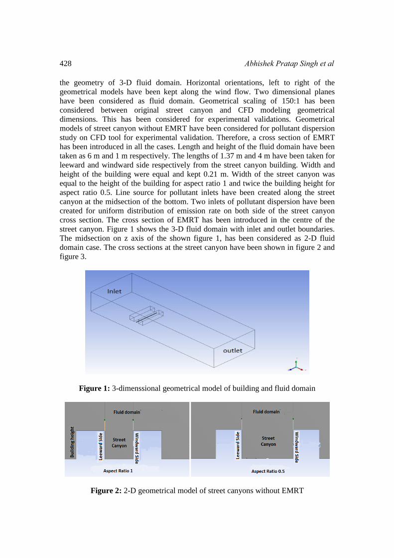
has been introduced in all the cases. Length and height of the fluid domain have been
taken as 6 m and 1 m respectively. The lengths of 1.37 m and 4 m have been taken for
leeward and windward side respectively from the street canyon building. Width and
height of the building were equal and kept 0.21 m. Width of the street canyon was
equal to the height of the building for aspect ratio 1 and twice the building height for
aspect ratio 0.5. Line source for pollutant inlets have been created along the street
canyon at the midsection of the bottom. Two inlets of pollutant dispersion have been
created for uniform distribution of emission rate on both side of the street canyon
cross section. The cross section of EMRT has been introduced in the centre of the
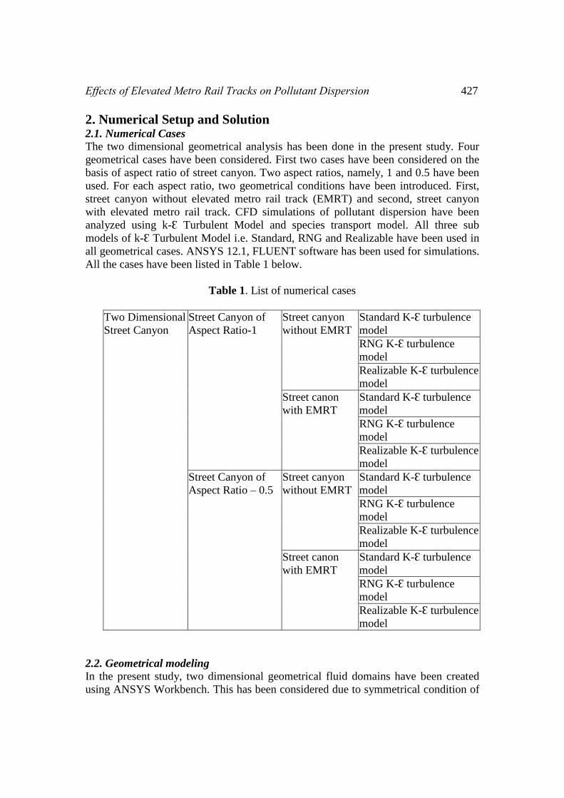
street canyon. Figure 1 shows the 3-D fluid domain with inlet and outlet boundaries.
The midsection on z axis of the shown figure 1, has been considered as 2-D fluid
domain case. The cross sections at the street canyon have been shown in figure 2 and
figure 3.
Figure 1: 3-dimenssional geometrical model of building and fluid domain
Figure 2: 2-D geometrical model of street canyons without EMRT

Effects of Elevated Metro Rail Tracks on Pollutant Dispersion 429
Figure 3: 2-D geometrical model of street canyons with EMRT
2.3. Mesh Generation
Differential volumetric analysis needs grid generation of the fluid domain. In the
present study meshing has been created using meshing tool of ANSYS software. To
keep uniformity of elements the different refinement tools have been used. Mapped
face meshing tool has been used for uniform distribution of grid elements in fluid
domain. Concentration of number of elements has been kept larger at cross section of
street canyon. Edge sizing has also been done. Composite planes of two dimensional
fluid domains have been differentiated in various rectangular shapes. This step has
been considered for uniformity of the different region. Surface area of fluid domain
has been calculated as 5.918 m2. Total elements in case of street canyon of aspect
ratio 1 without EMRT are 15850 with nodes number 48017.
Figure 4: Grid generation of the cross section of street canyon
2.4. Boundary Conditions
Fig. 5 shows all boundaries of the fluid domain i.e. air inlet, pollutant inlets, outlet,
symmetry, wall, building, and ground surface. Ambient air has been applied as wind
flow material with 1.67 m/s mean velocity at inlet boundary. User Defined Function
(UDF) has been applied at inlet for velocity profile. Mixture fluid material of air and
acetylene with 5 % proportion of acetylene and rest 95 % of air has been applied at
both pollutant inlets. Pollutant inlet flow velocity was kept 0.011 m/s. Outlet
condition has been kept as pressure outlet. Symmetry boundary condition has been
applied for upper horizontal boundary. All other boundaries have considered as no
slip wall condition.

430 Abhishek Pratap Singh et al
Figure 5: Boundaries of fluid domain
2.5. Physics Setups
ANSYS FLUENT CFD solver has been used to develop wind flow and pollutant
dispersion in two dimensional street canyons. Standard, RNG, and Realizable K-Ɛ
turbulence models have been applied in all geometrical cases. Transport species
equations model has been applied for pollutant dispersion. Appropriate boundary
conditions were applied as discussed earlier. A convergence criterion of 10-4 has been
applied in the calculations.
3. Results 3.1. Velocity vectors
Velocity vectors have been analyzed and discussed for all the cases of street canyon
and turbulence model. Figure 7 shows the velocity vectors at street canyon of aspect
ratio 1. From the figure, it is clear that the main vortex in the canyon dominates the
dispersion of pollutants. It is also clear that the significant variations in velocity
vectors pattern have been predicted by different k-Ɛ turbulence models. It has been
observed that standard k-Ɛ turbulence model computes velocity vectors similar to
those as in experimental study [18], as shown in figure 6. RNG k-Ɛ turbulence model
and realizable k-Ɛ turbulence model have predicted reverse vortex, which is not
acceptable while comparing to previous experimental and numerical studies. When
comparing velocity vectors of street canyon without EMRT with street canyon with
EMRT, it has been observed that vortex pattern has changed and shifted upward of
the street canyon centre. Velocity magnitudes in the lower corner of leeward and
windward side have decreased, which leads to increase in pollutants concentrations on

Effects of Elevated Metro Rail Tracks on Pollutant Dispersion 431
both the side. Vortex centre has shifted upward due to introduction of cross section of
EMRT. Lower part of street canyon becomes low velocity region, which leads to
increase in accumulation of pollutant concentrations.
Figure 6: Validation of velocity vectors (B) at street canyon cross section of the
model with simulation study [18] (A) for aspect ratio 1
Figure 7: Velocity vectors at street canyon of aspect ratio 1, (A) Street canyon
without EMRT, (B) Street Canyon with EMRT, (i) Standard k-Ɛ turbulence model (ii)
RNG k-Ɛ turbulence model (iii) Realizable k-Ɛ turbulence model.

432 Abhishek Pratap Singh et al
Figure 8 shows velocity vectors for street canyon of aspect ratio 0.5 for all the cases.
Standard k-Ɛ turbulence model predicts that, the major vortex is situated little bit to
windward side from centre of the street canyon. A small vortex has also been
observed at lower corner of the leeward side. On the other hand, RNG k-Ɛ turbulence
model and realizable turbulence model predicts a minor vortex on windward side.
While comparison with street canyon having EMRT, it was observed that pollutant
concentration and distribution of the pollutants did not change significantly.
Figure 8: Velocity vectors at street canyon of aspect ratio 0.5, (A) Street canyon
without EMRT, (B) Street Canyon with EMRT, (i) Standard k-Ɛ turbulence model (ii)
RNG k-Ɛ turbulence model (iii) Realizable k-Ɛ turbulence model.
3.2. Pollutant Contours
Figure 9 shows contours of pollutant, acetylene concentration at street canyon of
aspect ratio 1. Standard k-Ɛ turbulence model predicts similar pattern of concentration
contours as that of experiments results in accumulation of pollutants in street canyon.
Numerical study predicts higher pollutant concentration on leeward side. It has been
observed that, with the introduction of EMRT the pollutant concentrations increase at
leeward side and windward side for street canyon having EMRT. On the other side,
RNG k-Ɛ turbulence model and realizable k-Ɛ turbulence model predicts high
pollutant concentration at windward side and increase in pollutant concentration in
street canyon when EMRT is introduced. As RNG and Realizable models do not
validate the model, results may not be accepted. Increase in pollutants may be due to
restrictions in the main flow. Velocity magnitudes reduce in street canyon with
EMRT as compare to the street canyon without EMRT.
Figure 10 shows contours of pollutant concentration at street canyon of aspect ratio
0.5. It is clear from the figure that, introduction of EMRT does not cause any
significant change in accumulation of pollutants. Standard k-Ɛ turbulent model
computes similar pollutant concentration on both the cases.

Effects of Elevated Metro Rail Tracks on Pollutant Dispersion 433
Figure 9: Contours of pollutant concentration at street canyon of aspect ratio 1, (A)
Street canyon without EMRT, (B) Street Canyon with EMRT, (i) Standard k-Ɛ
turbulence model (ii) RNG k-Ɛ turbulence model (iii) Realizable k-Ɛ turbulence
model.
Figure 10. Contours of pollutant concentration at street canyon of aspect ratio 0.5,
(A) Street canyon without EMRT, (B) Street Canyon with EMRT, (i) Standard k-Ɛ
turbulence model (ii) RNG k-Ɛ turbulence model (iii) Realizable k-Ɛ turbulence
model.

434 Abhishek Pratap Singh et al
3.3. Pollutant concentration plots
Pollutant concentration on x-y coordinates has been plotted and discussed. Three
vertical sample lines as shown in figure 11, on each side of the street canyon have
been taken to plot pollutant concentrations. Vertical position and pollutant
concentrations have been taken on x-axis and y-axis respectively.
Figure 11: Sample lines taken to plot pollutant concentration on both the side of
street canyon, i.e., leeward (LW) and windward (WW) side.
Figure 12 and figure 13 shows pollutant concentration plot along the sample lines
taken on both leeward and windward side. For aspect ratio 1, it is clear from the figure
of pollutant concentration plot that pollutant concentration on leeward side has been
increased in street canyon having EMRT comparing to street canyon without EMRT.
Pollutant concentration has also been increased on windward side. It has been
observed that increase in pollutant concentration was along the complete line.

Effects of Elevated Metro Rail Tracks on Pollutant Dispersion 435
Figure 12: Pollutant concentration plot along street height in street canyon of aspect
ratio 1 (Leeward Side), (a) street canyon without EMRT (b) street canyon with EMRT
Figure 13: Pollutant concentration plot along street height in street canyon of aspect
ratio 1 (Windward Side), (a) street canyon without EMRT (b) street canyon with
EMRT
436 Abhishek Pratap Singh et al
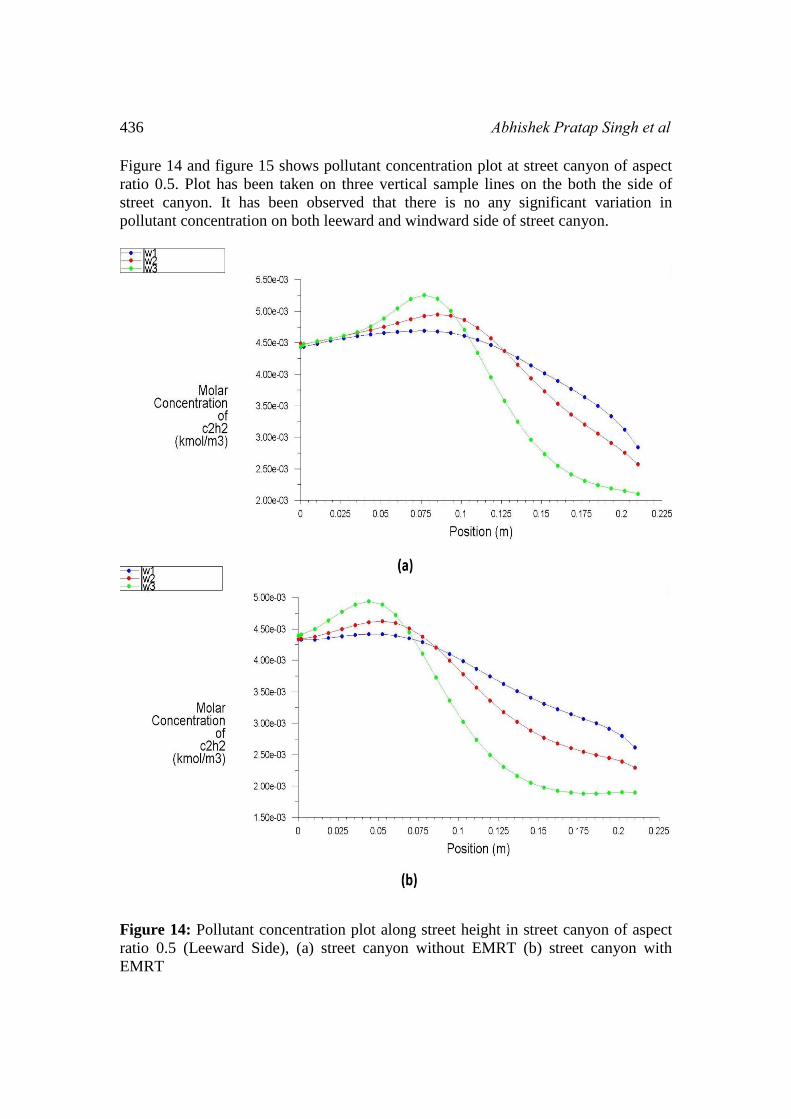
Figure 14 and figure 15 shows pollutant concentration plot at street canyon of aspect
ratio 0.5. Plot has been taken on three vertical sample lines on the both the side of
street canyon. It has been observed that there is no any significant variation in
pollutant concentration on both leeward and windward side of street canyon.
Figure 14: Pollutant concentration plot along street height in street canyon of aspect
ratio 0.5 (Leeward Side), (a) street canyon without EMRT (b) street canyon with
EMRT

Effects of Elevated Metro Rail Tracks on Pollutant Dispersion 437
Figure 15: Pollutant concentration plot along street height in street canyon of aspect
ratio 0.5 (Windward Side), (a) street canyon without EMRT (b) street canyon with
EMRT
Conclusion Urban street canyon of aspect ratio 1 and 0.5 were analyzed for pollutant dispersion
phenomena. ANSYS FLUENT software were used for CFD simulation of wind flow
and pollutant dispersion at street canyon. Effects of EMRT in street canyon were
compared with street canyon without EMRT for both the cases of aspect ratios.
Standard, RNG, and realizable k-Ɛ turbulence model were used to model wind flow
simulation. Standard k-Ɛ turbulence model had produced similar results when
compared to previous experimental results. Simulation results of the RNG and

438 Abhishek Pratap Singh et al
realizable k-Ɛ turbulence model were not acceptable when compared to experimental
studies. Pollutant concentrations were increased at different locations of street canyon
having EMRT on both leeward and windward side for aspect ratio 1. On the other side
pollutant concentration were not affected by introduction of EMRT at street canyon of
aspect ratio 0.5. It has been concluded that by introduction of any elevated transport
structure in normal street canyon, pollutant concentration and accumulation of
pollutants increases in street canyon. For two dimensional cases standard k-Ɛ
turbulence model predicts results that are similar to experimental results. Further
study of three dimensional cases will be more predictable model in all complex cases
of street canyon.
References
[1] Kastner-Klein, P., & Plate, E. J. (1999). Wind-tunnel study of concentration
fields in street canyons. Atmospheric Environment, 33(24), 3973-3979.
[2] Vardoulakis, S., Fisher, B. E., Pericleous, K., & Gonzalez-Flesca, N. (2003).
Modelling air quality in street canyons: a review. Atmospheric environment,37(2), 155-182.
[3] Chan, T. L., Dong, G., Leung, C. W., Cheung, C. S., & Hung, W. T. (2002).
Validation of a two-dimensional pollutant dispersion model in an isolated
street canyon. Atmospheric environment, 36(5), 861-872.
[4] Xie, X., Huang, Z., & Wang, J. S. (2005). Impact of building configuration on
air quality in street canyon. Atmospheric Environment, 39(25), 4519-4530.
[5] Ahmad, K., Khare, M., & Chaudhry, K. K. (2005). Wind tunnel simulation
studies on dispersion at urban street canyons and intersections—a
review.Journal of Wind Engineering and Industrial Aerodynamics, 93(9),
697-717.
[6] Yassin, M. F., Kellnerova, R., & Jaňour, Z. (2008). Impact of street
intersections on air quality in an urban environment. Atmospheric Environment, 42(20), 4948-4963.
[7] Memon, R. A., Leung, D. Y., & Liu, C. H. (2010). Effects of building aspect
ratio and wind speed on air temperatures in urban-like street canyons.Building and Environment, 45(1), 176-188.
[8] Baratian-Ghorghi, Z., & Kaye, N. B. (2013). The effect of canyon aspect ratio
on flushing of dense pollutants from an isolated street canyon. Science of the Total Environment, 443, 112-122.
[9] Takano, Y., & Moonen, P. (2013). On the influence of roof shape on flow and
dispersion in an urban street canyon. Journal of Wind Engineering and Industrial Aerodynamics, 123, 107-120.
[10] Madalozzo, D. M. S., Braun, A. L., Awruch, A. M., & Morsch, I. B. (2014).
Numerical simulation of pollutant dispersion in street canyons: Geometric and
thermal effects. Applied Mathematical Modelling, 38(24), 5883-5909.
[11] Huang, H., Ooka, R., Chen, H., Kato, S., Takahashi, T., & Watanabe, T.
(2008). CFD analysis on traffic-induced air pollutant dispersion under non-

Effects of Elevated Metro Rail Tracks on Pollutant Dispersion 439
isothermal condition in a complex urban area in winter. Journal of Wind Engineering and Industrial Aerodynamics, 96(10), 1774-1788.
[12] Gromke, C., Buccolieri, R., Di Sabatino, S., & Ruck, B. (2008). Dispersion
study in a street canyon with tree planting by means of wind tunnel and
numerical investigations–evaluation of CFD data with experimental
data.Atmospheric Environment, 42(37), 8640-8650.
[13] Kondo, H., & Tomizuka, T. (2009). A numerical experiment of roadside
diffusion under traffic-produced flow and turbulence. Atmospheric Environment, 43(27), 4137-4147.
[14] Vranckx, S., Vos, P., Maiheu, B., & Janssen, S. (2015). Impact of trees on
pollutant dispersion in street canyons: A numerical study of the annual
average effects in Antwerp, Belgium. Science of The Total Environment, 532,
474-483.
[15] Meroney, R. N., Pavageau, M., Rafailidis, S., & Schatzmann, M. (1996).
Study of line source characteristics for 2-D physical modelling of pollutant
dispersion in street canyons. Journal of Wind Engineering and Industrial Aerodynamics, 62(1), 37-56.
[16] Neofytou, P., Venetsanos, A. G., Rafailidis, S., & Bartzis, J. G. (2006).
Numerical investigation of the pollution dispersion in an urban street
canyon.Environmental Modelling & Software, 21(4), 525-531.
[17] Cheng, W. C., Liu, C. H., & Leung, D. Y. (2008). Computational formulation
for the evaluation of street canyon ventilation and pollutant removal
performance. Atmospheric Environment, 42(40), 9041-9051.
[18] Awasthi S., 2006, “Physical modelling and numerical simulation study of line
source dispersion in urban street canyon”. PhD thesis, Indian Institute of
Technology Delhi, India.

440 Abhishek Pratap Singh et al