effects of pounding on adjacent buildings of varying ... 1 of 19 civil & environmental...
TRANSCRIPT

Page 1 of 19
CIVIL & ENVIRONMENTAL ENGINEERING | RESEARCH ARTICLE
Effects of pounding on adjacent buildings of varying heights during earthquake in PakistanMuhammad Noman, Bashir Alam, Muhammad fahad, Khan Shahzada and Muhammad Kamal
Cogent Engineering (2016), 3: 1225878

Noman et al., Cogent Engineering (2016), 3: 1225878http://dx.doi.org/10.1080/23311916.2016.1225878
CIVIL & ENVIRONMENTAL ENGINEERING | RESEARCH ARTICLE
Effects of pounding on adjacent buildings of varying heights during earthquake in PakistanMuhammad Noman1*, Bashir Alam2, Muhammad Fahad2, Khan Shahzada2 and Muhammad Kamal3
Abstract: Pounding occurs when the adjacent buildings start vibration out of phase during the seismic activity which causes collision amongst the adjacent buildings. There are many mitigation techniques to avoid or minimize the effects of pounding including the provision of minimum separation gap between the adjacent buildings. Although all codes have provided the minimum separation gap requirements for the buildings, still a lot of study is required on this topic. This research aims at finding the minimum gap requirement for midrise buildings in Pakistan. Adjacent Buildings with different geometry and height are modelled in Sap2000 software with varying gap elements. Pushover and In-elastic time history analysis of these buildings are carried out using ground motion of Kashmir earthquake. Buildings are assumed to be resting on stiff soil. Material and sectional properties are also remained same for all cases. In order to reduce the pounding effects of two buildings, they were attached with each other and top displacements of buildings were compared with separate build-ings with inadequate gap. Column shear, maximum peak displacements and square root of sum of squares of maximum peak displacements were studied and the results
*Corresponding author: Muhammad Noman, Civil Engineering, University of Engineering and Technology, Taxila, Punjab, Pakistan E-mails: [email protected], [email protected]
Reviewing editor:Antonio Formisano, University of Naples Federico II, Italy
Additional information is available at the end of the article
ABOUT THE AUTHORSMuhammad Noman is pursuing his PhD in Civil Engineering from University of Engineering and Technology Taxila, Pakistan. He has done his BSc in Civil Engineering and MSc in Structural Engineering from Cecos University of I.T. and Emerging Sciences Peshawar, Pakistan in 2012 and 2015 respectively. His areas of interest are Structural modelling and repair.
Bashir Alam is Chairman in Civil Engineering department, University of Engineering and Technology Peshawar, Pakistan. He received his PhD in Civil Engineering from George Washington University, America.
Muhammad Fahad is Assistant Professor in Civil Engineering department, UET Peshawar, Pakistan. He received his PhD in Civil Engineering from University of Buffalo, America.
Khan Shahzada is Associate professor and director post graduate research in Civil Engineering department, UET Peshawar. He received his PhD in Civil Engineering from University of Engineering and Technology Peshawar, Pakistan.
Muhammad Kamal is pursuing MSc in structural Engineering from Cecos University Peshawar, Pakistan.
PUBLIC INTEREST STATEMENTEarthquake causes sudden ground motion and ground shaking which is transferred from the ground to the super structure through foundation. Building structures are often built close to each other. For example in dense populated areas, residential and office buildings are constructed very close to each other with very less or no gap. Due to earthquake induced ground motions, these buildings start vibrating out of phase and may collide with each other causing severe damage to structure, life and economy. This phenomenon of collision is known as pounding. This research aims at finding the minimum gap requirement for midrise buildings in Pakistan to avoid pounding effects in buildings. It was found that collision between buildings occur up to separation gap of six inch.
Received: 30 April 2016Accepted: 12 August 2016First Published: 20 August 2016
© 2016 The Author(s). This open access article is distributed under a Creative Commons Attribution (CC-BY) 4.0 license.
Page 2 of 19
Muhammad Noman

Page 3 of 19
Noman et al., Cogent Engineering (2016), 3: 1225878http://dx.doi.org/10.1080/23311916.2016.1225878
were plotted graphically. It was found out that pounding can occur up to separation gap of six inch. Maximum pounding occurs at the top floor level of smaller building. The requirement for minimum gap in UBC 97 is found out to be conservative.
Subjects: Concrete & Cement; Georisk & Hazards; Structural Engineering
Keywords: pounding; Sap2000; adjacent buildings; SRSS; gap requirement
1. IntroductionEarthquake causes sudden ground motion and ground shaking which is transferred from the ground to the super structure through foundation (Chopra, 2011). Building structures are often built close to each other. For example in dense populated areas, residential and office buildings are constructed very close to each other with very less or no gap. Due to earthquake induced ground motions, these buildings start vibrating out of phase and may collide with each other causing severe damage to structure, life and economy. This phenomenon of collision is known as pounding. “Pounding is a phenomenon, in which two buildings strike due to their lateral movements induced by lateral forces” (Raheem, 2013) “Seismic pounding is defined as the collision of adjacent buildings during earth-quakes” (Khatiwada, Chouw, & Butterworth, 2011). Pounding of adjacent buildings can be very dan-gerous because adjacent buildings have different dynamic characteristics which cause their out of phase vibration during earthquake. Thus cause damage due to insufficient gap or improper energy dissipation systems, to accommodate the relative motion of these buildings.
The main reason of the seismic pounding is the provision of insufficient gap or no gap in the building. The response of adjacent buildings towards external force is mainly due to following conditions:
• When the separation gap between adjacent buildings is inadequate.
• When building have sufficient gap but they are connected by one or more members.
• When adjacent buildings have different dynamic properties like mass, height, orientation, geome-try. It is almost impossible to construct two buildings with same dynamic properties. If the dynamic properties of two buildings are same, then there will be no pounding even if the gap is zero.
• When the centre of mass of adjacent buildings is not axial.
It is always necessary to emphasize that the attention should be shifted from post-emergency (even indispensable) to prevention, therefore setting up investigation programs before the disaster, focused on the evaluation of the vulnerability of structures which were not adequately designed, and providing enough resources for the generalized anti-seismic improvement of old masonry construc-tion, widely present in the Mediterranean Basin (Indirli, Kouris, Formisano, Borg, & Mazzolani, 2013).
Till now many damages of pounding effects are reported. Pounding of adjacent buildings have caused a lot of damage and in many cases caused complete collapse of buildings. Some of the re-ported cases of pounding include the Sanfernando earthquake of 1971. In this earthquake severe damage was caused by the olive view hospital which struck the outside stairway tower and caused permanent tilting of tower as shown in (Figure 1) (Jankowski & Mehmoud, 2009). Earthquake of 1985 in Mexico City which caused damage of more than 20% buildings; Loma Preita earthquake of 1989 with moment magnitude scale (Mw) of 7.1, which caused damage of over 200 structures. In this earthquake, two adjacent ten story and five story buildings situated at 90 km away from the epicen-tre experienced pounding. The gap between both buildings was about 4 cm. Pounding occurred at sixth story of ten story building and at top story of five story building (Aguilar, Jua´rez, Ortega, & Iglesias, 1989; Kasai & Maison, 1997; Lin & Weng, 2002). In 1999, structural pounding was observed in Taiwan due to Chi Chi earthquake. A school building in which new classes were built close to old ones experienced pounding due to insufficient gap. Pounding damage was also observed by build-ings in Christchurch CBD in 22nd February 2011 (Figure 2) due to earthquake of magnitude Mw 6.3 (Khatiwada et al., 2011). On April 6, 2009 a magnitude Mw = 6.3 normal-faulting earthquake struck

Page 4 of 19
Noman et al., Cogent Engineering (2016), 3: 1225878http://dx.doi.org/10.1080/23311916.2016.1225878
Figure 1. Permanent tilting of stairways of tower.
Figure 2. Pounding damage observed in Christchurch CBD, 2011.

Page 5 of 19
Noman et al., Cogent Engineering (2016), 3: 1225878http://dx.doi.org/10.1080/23311916.2016.1225878
the Abruzzo Region located in the central part of Italy, with an epicenter of shallow focal depth very close to L’Aquila, a city of about 73,000 inhabitants. This resulted in vast damage and collapse of several buildings, affecting not only old unreinforced masonry (URM) constructions, but surprisingly also some multi-storey reinforced concrete (RC) structures. (Decanini, Liberatore, & Mollaioli, 2010). The usability assessment of residential buildings of the historical centre of Castelvecchio Subequo after L’aquila earthquake was performed. This activity, carried out by filling ad hoc survey forms, has allowed to point out the main collapse mechanisms of masonry buildings, giving a clear picture of the damage level affecting the investigated built-up (Formisano, Feo, Grippa, & Florio, 2010). Analysis of the collected data for Castelvecchio Subequo, represents global collapse mechanism of buildings, such as irregularity among adjacent structures and floor and roof beam unthreading due to: perma-nent deformation of either tie-beams or their anchorages, with the failure of the former and the pull-out of the latter; diagonal cracks starting from the discontinuity between two adjacent build-ings; and vertical cracks along the interface between two adjacent buildings (Indirli et al., 2013). Some other notable earthquakes which caused pounding are Sequenay earthquake in Canada 1988, Cairo earthquake in 1992, Northridge earthquake in 1994, Kobe earthquake in 1995, Kocaeli earth-quake in 1999, Dilipur earthquake with Mw 6.5 in 2002, Sumatra earthquake with Mw 6.5 in 2004, Sikkin earthquake with Mw5.3 in 2006 Tohoku earthquake in 2011, etc. Seismic vulnerability assess-ment of masonry building aggregates within Italian historical centres represent a specific and very actual problem. The most vulnerable building is the one having the major number of floors and lo-cated at corner of the aggregate (Formisano, Landolfo, Mazzolani, & Florio, 2010). It is very difficult if not impossible to distinct the structurally independent units and to identify the global response of the building aggregate (Formisano, Florio, Landolfo, & Mazzolani, 2011).
Major areas of Pakistan are always under the threat of natural hazards (Earthquake). “Pakistan is considered to be situated in one of the world’s seismically active region” (Durrani, Elnashai, Hashash, Kim, & Masud, 2005). “The complete information regarding the historical earthquake records in Pakistan is not available” (Shahzada, 2011). However little data of this region is available. Some of the important earthquakes are shown in Table 1.
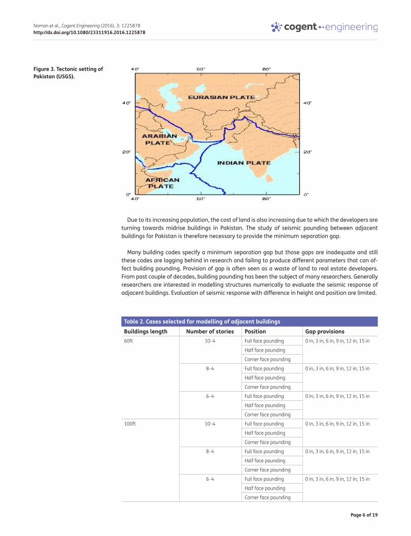
Pakistan is located at the junction of Eurasian and Indian plate as shown in Figure 3. These two plates are the main cause of earthquakes in Pakistan.
The Indian plate is moving towards the north at a rate of 4–5 cm/year and is sub-ducting under the Eurasian plate. The collision of these plates resulted in the separation of Indian plate into several segments under the Kashmir Basin. (Seeber & Armbruster, 1979)
Table 1. Important earthquakes in history of PakistanEarthquake Year IntensityTaxila earthquake 25 AD X
Srinagar earthquake 1555 AD X
Kunar 1842 6.7
Srinagar 1885 6.3
Kangra 1905 7.8
Quetta 1935 7.5
Pattan (Kohistan) 1974 6.2
Kashmir earthquake October, 2005 7.6
Dalbandin (Karachi) January, 2010 7.4
Kharan (Balochistan) January, 2011 7.4
Quetta April, 2013 7.9
Page 6 of 19
Noman et al., Cogent Engineering (2016), 3: 1225878http://dx.doi.org/10.1080/23311916.2016.1225878
Due to its increasing population, the cost of land is also increasing due to which the developers are turning towards midrise buildings in Pakistan. The study of seismic pounding between adjacent buildings for Pakistan is therefore necessary to provide the minimum separation gap.
Many building codes specify a minimum separation gap but those gaps are inadequate and still these codes are lagging behind in research and failing to produce different parameters that can af-fect building pounding. Provision of gap is often seen as a waste of land to real estate developers. From past couple of decades, building pounding has been the subject of many researchers. Generally researchers are interested in modelling structures numerically to evaluate the seismic response of adjacent buildings. Evaluation of seismic response with difference in height and position are limited.
Figure 3. Tectonic setting of Pakistan (USGS).
Table 2. Cases selected for modelling of adjacent buildingsBuildings length Number of stories Position Gap provisions60ft 10–4 Full face pounding 0 in, 3 in, 6 in, 9 in, 12 in, 15 in
Half face pounding
Corner face pounding
8–4 Full face pounding 0 in, 3 in, 6 in, 9 in, 12 in, 15 in
Half face pounding
Corner face pounding
6–4 Full face pounding 0 in, 3 in, 6 in, 9 in, 12 in, 15 in
Half face pounding
Corner face pounding
100ft 10–4 Full face pounding 0 in, 3 in, 6 in, 9 in, 12 in, 15 in
Half face pounding
Corner face pounding
8–4 Full face pounding 0 in, 3 in, 6 in, 9 in, 12 in, 15 in
Half face pounding
Corner face pounding
6–4 Full face pounding 0 in, 3 in, 6 in, 9 in, 12 in, 15 in
Half face pounding
Corner face pounding

Page 7 of 19
Noman et al., Cogent Engineering (2016), 3: 1225878http://dx.doi.org/10.1080/23311916.2016.1225878
This research study primarily focuses on minimizing the Pounding effects of buildings in Pakistan. The outcomes of this research work may be integrated in future building code of Pakistan. Geotechnical aspects are not studied.
2. Structural modeling and analysisFor a multi degree of freedom system the equation of motion is given as:
Equation (1) can be solved for determining the deformation response of the system with numerical methods. This is called time history analysis. The same method is followed for determining maxi-mum displacements of structures with varying heights, when subjected to strong ground excitation for studying the impact of pounding between the adjacent buildings.
Various cases of buildings are modeled is SAP2000. Table 2 shows; cases selected for analyzing minimum gap requirements in order to eliminate pounding effects in adjacent buildings. Figure 4(a) shows two adjacent ten story (F10) and four story (F4) buildings with length of 60ft prone to seismic pounding at their full face. Figure 4(b) shows two adjacent eight story (F8) and four story (F4) buildings with length of 60ft prone to seismic pounding at their half face. Figure 4(c) shows two adjacent six story (F6) and four story (F4) buildings with length of 60ft prone to seismic pounding at their corners.
(1)m��
v + c�
v + kv = p(t)
Figure 4a. Full faces pounding of F10 and F4, 60ft length.
Figure 4b. Half faces pounding of F8 and F4, 60ft length.

Page 8 of 19
Noman et al., Cogent Engineering (2016), 3: 1225878http://dx.doi.org/10.1080/23311916.2016.1225878
Figure 5 shows two adjacent ten story (F10) and four story (F4) buildings with length of 100ft prone to seismic pounding at their half face.
The plan views of 60ft long buildings and 100ft long buildings are shown in Figures 6(a) and 6(b) respectively. 60ft long building consist of 3 bays along x-axis and 2 bays along y-axis with each bay length of 20 × 25ft whereas 100ft long building consist of 5 bays along x-axis and 2 bays along y-axis with same bay length as that of 60ft long buildings.
Material properties those are assigned to the buildings include: Concrete Compressive Strength, fc′ = 3 ksi; Steel Yield Strength, fy = 40 ksi. The thickness of floor slabs is taken as six inch. The height of each story is taken as 11ft. Structure Elements are satisfying as per code requirements for gravity and lateral loads. The load patterns and load combinations are defined as per (IBC, 2009). Figure 5: Half faces pounding of F10 and F4, 100ft length.
After having modeled the structural components, all possible load cases are assigned. Gravity loads on the structure include the self-weight of beams, columns, slabs, walls and other permanent members. The self-weight of beams and columns (frame members) and slabs (area sections) is
Figure 4c. Corner face pounding of F6 and F4, 60ft length.
Figure 5. Half faces pounding of F10 and F4, 100ft length.

Page 9 of 19
Noman et al., Cogent Engineering (2016), 3: 1225878http://dx.doi.org/10.1080/23311916.2016.1225878
automatically considered by the program itself. Also a superimposed dead load of 30 psf is consid-ered on each floor level. Live loads have been assigned as uniform area loads on the slab elements as per ACSE7–05. Live load on roof applied is 60 psf. The soil profile selected was SC, very dense soil and soft rock. Importance factor of 1 and over strength factor of 8.5 is assigned.
Before running the analysis, in the modal load case, the mode type is selected as Ritz vector. The maximum numbers of modes are selected as 99 and 99% target dynamic participation ratios are used for both the accelerations and link (load types). The non-linear modal time history under the load case name as pounding is defined with the load type as acceleration values and time history function having a scale factor of 386.4 to convert g units into inch units. The non-linear static Push-over case is defined with Accel as load type along ux direction. Load application is monitored dis-placement and results are saved in multiple steps.
2.1. Gap elementsPounding is analyzed by using contact force-based model such as linear gap elements. A model idealization of adjacent structures and gap elements are shown in Figures 7(a) and 7(b) respectively. In Figures 7(a) and 7(b); K is stiffness of frame elements, h1 and h2 are heights of adjacent buildings, c1 and c2 represent damping values of both structures. In addition, a nonlinear interaction model accounting for impact energy dissipation is also presented to model pounding. A bilinear gap ele-ment contact model with a gap is considered with varying gaps for representing impact between closely spaced adjacent structures. Element hysteresis area to the energy dissipated during impact
Figure 6a. Plan view of 60ft long buildings.
Figure 6b. Plan view of 100ft long buildings.

Page 10 of 19
Noman et al., Cogent Engineering (2016), 3: 1225878http://dx.doi.org/10.1080/23311916.2016.1225878
is shown in Figure 7(c). Linear inelastic link elements for various lengths of 1″, 3″, 6″, 9″, 12″, 13″ and 14″ are provided in each case.
2.2. Stiffness of gap elementMany studies have been carried which suggest various assumptions for assigning stiffness to the spring element. These are illustrated as under:
• Wada et al. incorporated a gap element with stiffness equal to the axial stiffness of the beams and slab at the impact level (Wada, Shinozaki, & Nakamura, 1984).
• Anagnostopoulos suggested gap element with stiffness coefficient equal to twenty times the lateral stiffness of the more rigid SDOF system (Anagnostopoulos, 1988).
• Maison and Kasai proposed a stiffness value corresponding to the axial stiffness of the floor level at the assumed level of contact (Maison & Kasai, 1992).
Figure 7a. Model idealization of adjacent structures.
Figure 7b. Idealization of gap element.
Figure 7c. Element hysteresis area to the energy dissipated during impact.
Page 11 of 19
Noman et al., Cogent Engineering (2016), 3: 1225878http://dx.doi.org/10.1080/23311916.2016.1225878
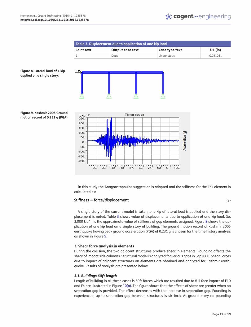
In this study the Anagnostopoulos suggestion is adopted and the stiffness for the link element is calculated as:
A single story of the current model is taken, one kip of lateral load is applied and the story dis-placement is noted. Table 3 shows value of displacements due to application of one kip load. So, 3,000 kip/in is the approximate value of stiffness of gap elements assigned. Figure 8 shows the ap-plication of one kip load on a single story of building. The ground motion record of Kashmir 2005 earthquake having peak ground acceleration (PGA) of 0.231 g is chosen for the time history analysis as shown in Figure 9.
3. Shear force analysis in elementsDuring the collision, the two adjacent structures produce shear in elements. Pounding affects the shear of impact side columns. Structural model is analyzed for various gaps in Sap2000. Shear Forces due to impact of adjacent structures on elements are obtained and analyzed for Kashmir earth-quake. Results of analysis are presented below.
3.1. Buildings 60ft lengthLength of building in all these cases is 60ft forces which are resulted due to full face impact of F10 and F4 are illustrated in Figure 10(a). The figure shows that the effects of shear are greater when no separation gap is provided. The effect decreases with the increase in separation gap. Pounding is experienced; up to separation gap between structures is six inch. At ground story no pounding
(2)Stiffness = force∕displacement
Table 3. Displacement due to application of one kip loadJoint text Output case text Case type text U1 (in)1 Dead Linear static 0.021031
Figure 8. Lateral load of 1 kip applied on a single story.
Figure 9. Kashmir 2005 Ground motion record of 0.231 g (PGA).

Page 12 of 19
Noman et al., Cogent Engineering (2016), 3: 1225878http://dx.doi.org/10.1080/23311916.2016.1225878
occurs where as in first and second story, three inch gap is sufficient. This means that three inch gap is sufficient for building whose height is up to three stories. For a four story building, three inch gap is not sufficient.
Shear forces which are resulted due to half face impact of F10 building and F4 buildings are illus-trated in Figure 10(b). The figure shows that the effects of shear are greater when no separation gap is provided that is zero inch gap. Ground, first and second story are safe in three inch gap. The effect decreases with the increase in separation gap. Pounding is experienced; up to separation gap be-tween structures is six inch.
Figure 10(c) shows shear forces which are resulted due to Corner face impact of F10 and F4. No pounding is occurring at ground, first and second story. After three stories the buildings are striking each other at three inch gap. So in these cases three inch gap is not sufficient. In fact six inch gap is sufficient in this case.
Figures 11(a)–11(c) shows shear forces which resulted due to full face, half face and corner face impact of F8 and F4 respectively. These figures illustrates that the effects of pounding are greater when no separation gap is provided. The effect decreases with the increase in separation gap. Pounding is experienced up to separation gap between structures is six inch. Comparatively the values of Shear in F8–F4 cases are greater than that for F10–F4.
Figure 10a. Shear forces due to full face pounding of F10 and F4, 60ft.
Figure 10b. Shear forces due to half face pounding of F10 and F4, 60ft.
Figure 10c. Shear forces due to corner face pounding of F10 and F4, 60ft.

Page 13 of 19
Noman et al., Cogent Engineering (2016), 3: 1225878http://dx.doi.org/10.1080/23311916.2016.1225878
Figures 12(a)–12(c) illustrates shear forces which resulted due to full face, half face and corner face impact of F6 and F4 respectively. These figure shows almost same result for gap element as those of other cases which is the effects of shear are greater when no separation gap is provided. The effect decreases with the increase in separation gap. Pounding is experienced; up to separation gap between structures is six inch. Comparatively the values of Shear in F8–F4 cases are greater than that for F10–F4 Cases.
Figure 11a. Shear forces due to Full face pounding of F8 and F4, 60ft.
Figure 11b. Shear forces due to half face pounding of F8 and F4, 60ft.
Figure 11c. Shear forces due to corner face pounding of F8 and F4, 60ft.
Figure 12a. Shear forces due to full face pounding of F6 and F4, 60ft.

Page 14 of 19
Noman et al., Cogent Engineering (2016), 3: 1225878http://dx.doi.org/10.1080/23311916.2016.1225878
3.2. Buildings 100ft lengthLengths of buildings in these cases are kept 100ft whereas the height is varying. Figures 13(a)–13(c) shows shear forces which are resulted due to full face, half face and corner face impact of F10 and F4 respectively. In these cases the length of both buildings susceptible to pounding are increased to 100ft as shown in plan view Figures 6(a) and 6(b). Buildings are still showing pounding effects up to separation gap of six inch.
Figure 12b. Shear forces (kips) due to half face pounding of F6 and F4, 60ft.
Figure 12c. Shear forces (kips) due to corner face pounding of F6 and F4, 60ft.
Figure 13a. Shear forces due to full face pounding of F10 and F4, 100ft.
Figure 13b. Shear forces due to half face pounding of F10 and F4, 100ft.

Page 15 of 19
Noman et al., Cogent Engineering (2016), 3: 1225878http://dx.doi.org/10.1080/23311916.2016.1225878
3.3. Shear force comparison at six inch gapThe buildings are designed for all above load cases and earthquakes. From this research work it is clear that pounding do not occur after provision of 6 inch gap. Results of all these forces at 6 inch gap are compared as illustrated in Figure 14.
4. DisplacementsThe Uniform building Code UBC 1997 which is followed by USA as well as adopted by Pakistan Building Code, states that pounding effect is because of sum of Square roots of Peak inelastic Displacement response of adjacent structures. According to UBC 97, the minimum Gap required between two adjacent buildings is equal to the square root of sum of squares of maximum displace-ments (SRSS) of each building.
Figure 13c. Shear forces due to corner face pounding of F10 and F4, 100ft.
Figure 14. Shear forces (kips) comparison at 6 inch gap.
Figure 15. Displacements by SRSS of 60ft wide buildings.

Page 16 of 19
Noman et al., Cogent Engineering (2016), 3: 1225878http://dx.doi.org/10.1080/23311916.2016.1225878
Figures 15 and 16 represent three different cases of 60ft and 100ft lengthy buildings with vary-ing heights by Square root of sum of squares of maximum displacements (inches) of F10–F4, F8–F4 and F6–F4 each with full face impact half face impact and corner face impact respectively.
These figures show the value of required minimum gap as per UBC 97 is much greater (7–10 inches) than the actual value required (i.e. six inch).
5. Mitigation measuresSeismic pounding can be prevented by providing adequate separation gap. But this is not always possible due to high value of land, limited availability of land space, already constructed building in vicinity and many other reasons. In such cases there should be alternate methods to avoid seismic gap. In this research two cases are assumed:
• Four story building to be constructed next to ten story building.
• Four story building to be constructed next to six story building.
The columns exposed to pounding side of ten story building and six story building are attached to one another to act like one single column as shown in Figure 17 and top displacements of both these structures are checked. It is found that the top displacement of connected structures is reduced to 68% than they were separate. Difference of results are shown in Figure 18.
Figure 16. Displacements by SRSS of 100ft wide buildings.
Figure 17. F6 and F4 structures combined for mitigation of pounding.

Page 17 of 19
Noman et al., Cogent Engineering (2016), 3: 1225878http://dx.doi.org/10.1080/23311916.2016.1225878
5. ConclusionsFollowing Conclusions based on pounding effects of buildings in Pakistan are made:
• Effects of shear are greater when no separation gap is provided. The effect decreases with the increase in separation gap. Pounding is experienced; up to separation gap between structures is six inch.
• The maximum pounding occurs at fourth story which is the top floor of F4 building. At ground story no pounding occurs where as in 1st and 2nd story, three inch gap is sufficient. This means that three inch gap is sufficient for building whose height is up to 3 stories. For a four story build-ing, three inch gap is not sufficient.
• Pounding effects between F6and F4 is greater than F10–F4. This is due to difference in time pe-riod of F6–F4 which matches the ground motion more than F10–F4 buildings.
• Gap requirement from UBC 97 code is conservative. At full face pounding UBC 97 formulae gives approximately same results but when building’s position is not full face than gap requirements are changed and therefore formulae from UBC 97 cannot be used.
• Top displacement of connected structures is reduced to 68% than they were separate.
6. Recommendations
(1) A minimum of six inch gap must be provided for adjacent buildings whose story height is be-tween 4 and 10 located in area where seismicity in terms of g is similar to Abbottabad.
(2) Building regulatory authorities should enforce the minimum gap requirements in order to pre-vent pounding damage.
(3) In more complex structures, minimum gap requirements should be checked by advance struc-tural analysis software such as Sap2000 or Etabs as well as practically on shake table by mak-ing their prototypes.
7. Future work
(1) Effect of soil flexibility on structural response shall be studied in order to achieve realistic as-sessment and its adverse effect on adjacent structures.
(2) Different types of impact models may be studied and may be experimentally verified so that future simulations may be more realistic.
(3) Evaluation of different numerical structural impact models may be done.
Figure 18. Difference of separated structures and connected structures.

Page 18 of 19
Noman et al., Cogent Engineering (2016), 3: 1225878http://dx.doi.org/10.1080/23311916.2016.1225878
(4) Floor accelerations should be studied which may also lead to evaluation of non-structural damage done during the pounding effects.
(5) Pounding effects with on irregular structures should be studied.
(6) Pounding in buildings in series requires study for other cities of Pakistan and a proper table for all cities of Pakistan shall be prepared.
(7) Mitigation studies in detail are required.
Author detailsMuhammad Noman1
E-mails: [email protected], [email protected] Alam2
E-mail: [email protected] Fahad2
E-mail: [email protected] Shahzada2
E-mail: [email protected] Kamal3
E-mail: [email protected] Civil Engineering, University of Engineering and Technology,
Taxila, Punjab, Pakistan.2 Civil Engineering, University of Engineering and Technology,
Peshawar, Pakistan.3 Structural Engineering, CECOS University Peshawar, Pakistan.
Citation informationCite this article as: Effects of pounding on adjacent buildings of varying heights during earthquake in Pakistan, Muhammad Noman, Bashir Alam, Muhammad Fahad, Khan Shahzada & Muhammad Kamal, Cogent Engineering (2016), 3: 1225878.
Cover imageTime History Analysis.Software: SAP2000.Source: Authors.
ReferencesAguilar, J., Jua´rez, H., Ortega, R., & Iglesias, J. (1989). The
Mexico Earthquake of September 19, 1985—Statistics of Damage and of Retrofitting Techniques in Reinforced Concrete Buildings Affected by the 1985 Earthquake. Earthquake Spectra, 5, 145–151. http://dx.doi.org/10.1193/1.1585516
Anagnostopoulos, S. A. (1988). Pounding of buildings in series during earthquakes. Earthquake Engineering and Structural Dynamics, 16, 443–456. http://dx.doi.org/10.1002/(ISSN)1096-9845
Chopra, A. K. (2011). Dynamics of structure, theory and applications to earthquake engineering (4th ed.). Berkeley, CA: Prentice Hall.
Decanini, L., Liberatore, L., & Mollaioli, F. (2010). Damage suffered by R. C. buildings during the 2009 L’Aquila earthquake, a general overview and a case study. In Proceedings of the 14ECEE (p. 443). Ohrid, Republic of Macedonia.
Durrani, A., Elnashai, A., Hashash, Y., Kim, S., & Masud, A. (2005). The Kashmir earthquake of October 08, 2005: A quick look report. Urbana Champaign, IL: Mid-America Earthquake Center, University of Illinois.
Formisano, A., Feo, P., Grippa, M., & Florio, G. (2010). L’Aquila earthquake: A survey in the historical centre of Castelvecchio Subequo. In COST ACTION C26: Urban
Habitat Constructions under Catastrophic Events - Proceedings of the Final Conference (pp. 371–376). Naples.
Formisano, A., Florio, G., Landolfo, R., & Mazzolani, F. M. (2011). Numerical calibration of a simplified procedure for the seismic behaviour assessment of masonry building aggregates. In Proceedings of the 13th International Conference on Civil, Structural and Environmental Engineering Computing (p. 28). Greece.
Formisano, A., Landolfo, R., Mazzolani, F. M., & Florio, G. (2010). A quick methodology for seismic vulnerability assessment of historical masonry aggregates. In COST ACTION C26: Urban Habitat Constructions under Catastrophic Events - Proceeding of the final Conference (pp. 577–582). Naples.
IBC (International Building Code). (2009). International Code Concil.
Indirli, M., Kouris, L. A., Formisano, A., Borg, R. P., & Mazzolani, F. M. (2013). Seismic damage assessment of unreinforced masonry structures after the abruzzo 2009 earthquake: The case study of the historical centers of L'Aquila and Castelvecchio Subequo. International Journal of Architectural Heritage, 7, 536–578. http://dx.doi.org/10.1080/15583058.2011.654050
Jankowski, R., & Mehmoud, S. (2009). Elastic and inelastic multi-story buildings under earthquake excitation with effect of pounding. Journal of Applied Sciences, 9, 3250–3262.
Kasai, K., & Maison, B. (1997). Building pounding damage during the 1989 Loma Prieta earthquake. Engineering Structures, 19, 195–207. http://dx.doi.org/10.1016/S0141-0296(96)00082-X
Khatiwada, S., Chouw, N., & Butterworth, J. W. (2011, April 14–16). Development of pounding model for adjacent structures in earthquakes. In Proceeding of 9th Pacific Conference on Earthquake Engineering. Auckland.
Lin, J.-H., & Weng, C.-C. (2002). A study on seismic pounding probability of buildings in Taipei metropolitan area. Journal of the Chinese Institute of Engineers, 25, 123–135. http://dx.doi.org/10.1080/02533839.2002.9670687
Maison, B. F., & Kasai, K. (1992). Dynamics of pounding when two buildings collide. Earthquake Engineering and Structural Dynamics, 21, 771–786. http://dx.doi.org/10.1002/(ISSN)1096-9845
Raheem, S. E. (2013). Mitigation measures for seismic pounding effects on adjacent buildings responses. Computational Methods in Structural Dynamics and Earthquake Engineering, 12, 1705–1724.
Seeber, L., & Armbruster, J. (1979). Seismicity of the hazara arc in Northern Pakistan: Decollement vs. basement faulting. In Farah A. & DeJong K. A. (Eds.), Geo dynamics of Pakistan (pp. 131–142). Quetta: Geological Survey of Pakistan.
Shahzada, K. (2011). Seismic risk assessment of buildings in Pakistan (PhD Thesis). University of Engineering and Technology Peshawar, Pakistan, Peshawar.
Wada, A., Shinozaki, Y., & Nakamura, N. (1984). Collapse of building with expension joints through collision caused by earthquake motion (pp. 855–862). 8th World Conference on Earthquake Engineering, San Francisco, CA.

Page 19 of 19
Noman et al., Cogent Engineering (2016), 3: 1225878http://dx.doi.org/10.1080/23311916.2016.1225878
© 2016 The Author(s). This open access article is distributed under a Creative Commons Attribution (CC-BY) 4.0 license.You are free to: Share — copy and redistribute the material in any medium or format Adapt — remix, transform, and build upon the material for any purpose, even commercially.The licensor cannot revoke these freedoms as long as you follow the license terms.
Under the following terms:Attribution — You must give appropriate credit, provide a link to the license, and indicate if changes were made. You may do so in any reasonable manner, but not in any way that suggests the licensor endorses you or your use. No additional restrictions You may not apply legal terms or technological measures that legally restrict others from doing anything the license permits.
Cogent Engineering (ISSN: 2331-1916) is published by Cogent OA, part of Taylor & Francis Group. Publishing with Cogent OA ensures:• Immediate, universal access to your article on publication• High visibility and discoverability via the Cogent OA website as well as Taylor & Francis Online• Download and citation statistics for your article• Rapid online publication• Input from, and dialog with, expert editors and editorial boards• Retention of full copyright of your article• Guaranteed legacy preservation of your article• Discounts and waivers for authors in developing regionsSubmit your manuscript to a Cogent OA journal at www.CogentOA.com