effects of roughness of gas diffusion layer surface on liquid
TRANSCRIPT

This article was downloaded by: [Xi'an Jiaotong University]On: 02 August 2012, At: 16:44Publisher: Taylor & FrancisInforma Ltd Registered in England and Wales Registered Number: 1072954 Registeredoffice: Mortimer House, 37-41 Mortimer Street, London W1T 3JH, UK
Numerical Heat Transfer, Part A:Applications: An International Journal ofComputation and MethodologyPublication details, including instructions for authors andsubscription information:http://www.tandfonline.com/loi/unht20
Effects of Roughness of Gas DiffusionLayer Surface on Liquid Water Transportin Micro Gas Channels of a ProtonExchange Membrane Fuel CellLi Chen a , HuiBao Luan a , Ya-Ling He a & Wen-Quan Tao aa Key Laboratory of Thermo-Fluid Science and Engineering of MOE,School of Energy and Power Engineering, Xi'an Jiaotong University,Xi'an, Shaanxi, P.R. China
Version of record first published: 02 Aug 2012
To cite this article: Li Chen, HuiBao Luan, Ya-Ling He & Wen-Quan Tao (2012): Effects of Roughnessof Gas Diffusion Layer Surface on Liquid Water Transport in Micro Gas Channels of a Proton ExchangeMembrane Fuel Cell, Numerical Heat Transfer, Part A: Applications: An International Journal ofComputation and Methodology, 62:4, 295-318
To link to this article: http://dx.doi.org/10.1080/10407782.2012.670586
PLEASE SCROLL DOWN FOR ARTICLE
Full terms and conditions of use: http://www.tandfonline.com/page/terms-and-conditions
This article may be used for research, teaching, and private study purposes. Anysubstantial or systematic reproduction, redistribution, reselling, loan, sub-licensing,systematic supply, or distribution in any form to anyone is expressly forbidden.
The publisher does not give any warranty express or implied or make any representationthat the contents will be complete or accurate or up to date. The accuracy of anyinstructions, formulae, and drug doses should be independently verified with primarysources. The publisher shall not be liable for any loss, actions, claims, proceedings,demand, or costs or damages whatsoever or howsoever caused arising directly orindirectly in connection with or arising out of the use of this material.

EFFECTS OF ROUGHNESS OF GAS DIFFUSION LAYERSURFACE ON LIQUID WATER TRANSPORT IN MICROGAS CHANNELS OF A PROTON EXCHANGEMEMBRANE FUEL CELL
Li Chen, HuiBao Luan, Ya-Ling He, and Wen-Quan TaoKey Laboratory of Thermo-Fluid Science and Engineering of MOE,School of Energy and Power Engineering, Xi’an Jiaotong University,Xi’an, Shaanxi, P.R. China
Effects of surface roughness of a gas diffusion layer (GDL) on liquid water transport in a
micro gas channel (GC) of a proton exchange membrane fuel cell (PEMFC) are investi-
gated by using the volume of fluid (VOF) method in the commercial CFD package, FLU-
ENT 6.3.26. An array of cubic holes under the GDL surface is used to describe the GDL
surface roughness. The simulation results show that a Cassie droplet is inclined to form on
the hydrophobic rough GDL surface and the surface roughness greatly affects the transport
of the droplet. Effects of GDL surface roughness on forces acting on the droplet are carefully
studied, and it is found that GDL surface roughness reduces the retentive forces and increases
the detaching forces. In addition, effects of GDL surface roughness on the time required for a
droplet to be removed out of the GC, liquid water coverage area ratio on GDL surface, and
pressure drop in the GC are explored. The removal time of the water droplet decreases as the
GDL roughness increases. The water coverage ratio of the GDL surface decreases as GDL
surface roughness increases. The pressure drop in the GC increases as the GDL surface
roughness increases.
1. INTRODUCTION
The proton exchange membrane fuel cell (PEMFC) is a promising candidate ofpower source for a range of applications because of its notable advantages such ashigh power density, high efficiency, low operation temperature, low noise, and nopollutions. However, PEMFC requires further improvements to achieve wide com-mercial use, particularly in regard to cell performance. To improve performanceof PEMFC, proper water managements are urgently demanded. Successful watermanagement in the PEMFC, particularly in the cathode side, is crucial to the cellperformance, as poor water management results in either dehydration of the mem-brane or flooding issues. On the one hand, membrane dehydration increases the
Received 22 July 2011; accepted 13 February 2012.
The authors thank the National Nature Science Foundation of China (no. 51136004) for
supporting this work.
Address correspondence to Wen-Quan Tao, Key Laboratory of Thermo-Fluid Science and
Engineering of MOE, School of Energy and Power Engineering, Xi’an Jiaotong University, Xi’an,
Shaanxi 710049, P.R. China. E-mail: [email protected]
Numerical Heat Transfer, Part A, 62: 295–318, 2012
Copyright # Taylor & Francis Group, LLC
ISSN: 1040-7782 print=1521-0634 online
DOI: 10.1080/10407782.2012.670586
295
Dow
nloa
ded
by [
Xi'a
n Ji
aoto
ng U
nive
rsity
] at
16:
44 0
2 A
ugus
t 201
2

proton conductive resistance and thus reduces the cell performance owing to greatohmic loss across the membrane. On the other hand, flooding problems occur ifexcessive liquid water accumulates in the components of a PEMFC including gaschannel (GC), gas diffusion layer (GDL), and catalyst layer (CL). Flooding can ser-iously debilitate cell performance which concretely presents as three sub-categoryflooding issues. On the microscopic scale, liquid water covers the CL surface, cre-ating hindered oxygen transport and reduced reactive surface. On the mesoscopicscale, liquid water clogs pores of GDL, decreasing the effective transport of gaseousreactant to the reactive site. On the macroscopic scale, liquid water blocks the GC,resulting in mal-distribution of oxygen and an increase in parasitic pumping powerto overcome the increased pressure drop. Therefore, much research has highlightedand emphasized the requirement of proper water management and have endeavoredto investigate liquid water transport processes in the components of a PEMFC.Reviews of these studies have been conducted in references [1–3].
Liquid water dynamics in the GC is one of the most important issues in theprocess of water management, which has been extensively studied during the pastseveral years [3]. Liquid water transport and distribution in the GC are affectedby various operating conditions: air flow rate significantly affects liquid water distri-bution and leads to different water flow patterns [4]; decreasing the inlet humidity ofthe reactants can greatly mitigate buildup of liquid water [5]; raising the operatingtemperature can considerably reduce the liquid water content [6]; and operatingPEMFC under different loads’ results in various liquid water distribution [7]. Inaddition, liquid water distributions in the GC are also affected by several geometrical
NOMENCLATURE
Ar liquid water area fraction at the outlet
of GC
Aw area of water at the GC outlet, m2
Aoutlet total area of the GC outlet, m2
b height between the top of the droplet
and the top wall of the GC, m
C volume fraction function
Fad surface tension force due to interface
pressure difference across the water-air
interface, N
Fb buoyancy force, N
Fg gravity force, N
Fl lift force, N
Fp pressure force, N
FR surface tension force due to water
deformation, N
Fr surface tension force due to water
connected to the emergence pore, N
Fs shear force, N
g gravity acceleration, m s�2
h the height of the liquid water
droplet, m
H height of the GC, m
l diameter of the contact area between
liquid water and the GDL surface, m
n surface normal
P pressure, Pa
r radius of the emergence pore, m
R radius of the water droplet, m
Re Reynold number
t time, s
u velocity, m s�1
V volume of the water droplet, m3
m dynamic viscosity, N s m�2
r surface tension between water and air,
N m�1
h contact angle
ha advancing contact angle
hr receding contact angle
q density, kg m�3
t kinematic viscosity, m2 s�1
Subscripts
a air
in inlet
w water
296 L. CHEN ET AL.
Dow
nloa
ded
by [
Xi'a
n Ji
aoto
ng U
nive
rsity
] at
16:
44 0
2 A
ugus
t 201
2
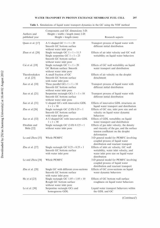
Table 1. Simulations of liquid water transport dynamics in the GC using the VOF method
Authors and
published year
Components and GC dimensions 3-D:
Height�width� length (mm) 2-D:
Height� length (mm) Research aspects
Quan et al. [17] A U-shaped GC 1� 1� 20
Smooth GC bottom surface
without water inlet pore
Transport process of liquid water with
different initial distribution
Zhan et al. [20] Single rectangle GC 1� 1� 11.5
Single serpentine GC 1� 1� 23
Smooth GC bottom surface
without water inlet pore
Effects of air inlet velocity and GC wall
wettability on liquid water behaviors
Cai et al. [19] Single rectangle GC 1� 1� 20
GC Bottom surface: Smooth
without water inlet pore
Effects of GC wall wettability on liquid
water transport and distribution
Theodorakakos
et al. [25]
A small fraction of GC
Smooth GC bottom surface
with water inlet pore
Effects of air velocity on the droplet
detachment
Jiao et al. [18] Three parallel GCs 1� 1� 10
Smooth GC bottom surface
without water inlet pore
Transport process of liquid water with
different initial distribution
Jiao et al. [21] Serpentine rectangle GCs 1� 1� 10
Smooth GC bottom surface
without water inlet pore
Transport process of liquid water with
different initial distribution
Jiao et al. [31] U-shaped GCs with innovative GDL
1� 1� 30
Effects of innovative GDL structures on
liquid water transport and distribution
Zhu et al [26] Single rectangle GC (2-D) 0.25� 1
Smooth GC bottom surface
with water inlet pore
Effects of GC size, inlet pore size and air
velocity on liquid water dynamic
behaviors
Jiao et al. [32] A U-shaped GC with innovative GDL
1� 1� 30
Effects of GDL wettability on liquid
water transport and distribution
Ebrahim and
Shila [22]
Single rectangle GC (2-D) 0.125� 1
without water inlet pore
Effects of gas inlet velocity, the density
and viscosity of the gas, and the surface
tension coefficient on the droplet
deformation
Le and Zhou [33] Whole PEMFC 3-D general model for PEMFC involving
coupled process of liquid water
distribution and reactant transport
Zhu et al. [27] Single rectangle GC 0.25� 0.25� 1
Smooth GC bottom surface
with water inlet pore
Effects of inlet air velocity, GC wall
wettability, water inlet velocity, and
water inlet pore size on liquid water
distribution
Le and Zhou [34] Whole PEMFC 3-D general model for PEMFC involving
coupled process of liquid water
distribution and reactant transport
Zhu et al. [28] Single GC with different cross-sections
Smooth GC bottom surface
with water inlet pore
Effects of GC cross-sections on liquid
water dynamic behaviors
He et al [23] Single rectangle GC 1.05� 1.05� 10
Rough GC bottom surface
without water inlet pore
Effects of GC bottom wall surface
roughness on liquid water behaviors
Le et al. [30] Serpentine rectangle GCs and
homogenous GDL
Liquid water transport behaviors within
the GDL and GC
(Continued )
WATER TRANSPORT IN PROTON EXCHANGE MEMBRANE FUEL CELL 297
Dow
nloa
ded
by [
Xi'a
n Ji
aoto
ng U
nive
rsity
] at
16:
44 0
2 A
ugus
t 201
2

parameters (e.g., GC layout, GC surface wettability, and land=channel width ratio).Different layouts of GC (currently, parallel, interdigitated, and serpentine layoutsare the most commonly adopted layouts) create different liquid water distributionin the GC [8]. The geometrical configuration of the channel also greatly impactsthe liquid water distribution in the GC, including the cross-section of the GC [9],the channel number and the land=channel width ratio [10], and the GC surfacewettability [11].
Numerical simulations have been performed to investigate the effects of vari-ous operating conditions and geometrical parameters on liquid water behaviors inthe GC. A multiphase mixture model [12, 13] and multi-fluid multi-phase model[14–16] have been widely adopted in modeling two-phase flow problems. Recently,the volume of fluid (VOF) method has also been applied to explore liquid waterbehaviors in the GC, due to its capacity of considering surface tension and walladhesion and of tracking liquid-gas interface [17–34]. Table 1 presents a brief intro-duction to those numerical studies using VOF. These studies can be divided to dif-ferent groups based on different classifications. For the computational domain, somefocused on the GC [17–19], some further considered the cathode of the PEMFC[30–32], and some comprehensively took the whole PEMFC into account [33, 34].For initial liquid water distribution, some started the simulation with initial givenliquid water distribution [17–24, 30, 33, 34], while others performed the simulationwith liquid water gradually entering the GC from GDL pores [25–29, 31, 32]. Forthe GC bottom surface which consisted of GDL, some simply used a smooth bottomsurface [17–29] while some tried to involve the GDL surface roughness [23, 29]. Forthe coupling process of liquid water and reactants transport, some concentrated onthe liquid water behaviors [17–32] and some further [33, 34] simulated the coupledprocess of liquid water and reactant transports. Besides, the above simulations putan emphasis on different factors that affect liquid water formation and movement,e.g., gas or liquid water velocity, contact angle hysteresis, wall wettability, surfaceroughness, GC dimensions, cross-section shape of GC, and GC layout. The abovestudies have revealed that liquid water distribution in the GC is highly variableand liquid water transport in the GC is significantly complicated for its inherentlyunsteady and nonlinear characteristics.
In PEMFC, the GC is usually carved in the bipolar plate which is directlyadjacent to the porous GDL. Therefore, three walls of a GC (the top and two side
Table 1. Continued
Authors and
published year
Components and GC dimensions 3-D:
Height�width� length (mm) 2-D:
Height� length (mm) Research aspects
Ding et al. [29] Single rectangle GC 0.25� 0.25� 1.25
Partially rough GC bottom surface
with water inlet pore
Effects of water inlet pore structure, water
inlet velocity, and GC wall wettability
on liquid water distribution
Akhtar and
Kerkhof [24]
Single tapered channel length: 20
Height�width (inlet): 1� 1
Height�width (outlet): 0.5� 1
Smooth GC bottom surface
without water inlet pore
Effects of wall wettability on liquid water
behaviors.
298 L. CHEN ET AL.
Dow
nloa
ded
by [
Xi'a
n Ji
aoto
ng U
nive
rsity
] at
16:
44 0
2 A
ugus
t 201
2

walls in this study) consist of bipolar plate material and the fourth wall (the bottomwall in this study) is composed of the GDL. The GDL has very complex microscopicstructures. Figure 1 shows an SEM image of a carbon paper GDL. Clearly, the com-plex and nonuniform structures of GDL create a rough bottom surface of a GC. In amicro GC, such a rough bottom surface significantly affects liquid water transportand distribution [29]. This is because surface tension force, which plays an importantrole on liquid water dynamics in micro GC, is closely related to surface roughness.However, to the best of our knowledge, few studies have considered the rough sur-face of the GDL when studying liquid water dynamic behaviors in the GC. Only veryrecently, He et al. [23] distributed long rectangles on the GC bottom surface todescribe GDL surface roughness, and the simulation results revealed a great impactof GDL surface roughness on liquid water transport processes. Ding et al. [29]arranged cube holes dispersed on the GDL surface and they found out that theGDL surface microstructures give rise to various liquid water flow patterns.
The objective of the present study is to investigate the effeets of GDL surfaceroughness on liquid water behaviors in a micro GC of a PEMFC. Emphasis is placedon the effects of roughness on forces affecting liquid water transport and the resultingpressure drop in the GC, liquid water coverage area on the GDL surface, and liquidwater removal rate. The following sections are arranged. The computational domain,computational methodology, and boundary and initial conditions are introduced insection 2. In section 3, the effects of GDL surface properties on forces acting on liquidwater, liquid water removal rate, liquid water coverage area onGDL surface, and press-ure drop in the GC are investigated in detail. Finally, a conclusion is given in section 4.
2. NUMERICAL MODEL
2.1. Computational Domain
As mentioned above, liquid water transport processes in the GC are affected bymany operating parameters and geometrical parameters. In this study, we focus onthe effects of GDL surface roughness on liquid water behaviors in the GC. There-fore, all the operating conditions including air inlet velocity, operating temperature,and operating pressure are kept constant. Geometrical parameters including GC
Figure 1. Microstructure of carbon paper GDL.
WATER TRANSPORT IN PROTON EXCHANGE MEMBRANE FUEL CELL 299
Dow
nloa
ded
by [
Xi'a
n Ji
aoto
ng U
nive
rsity
] at
16:
44 0
2 A
ugus
t 201
2
height, GC width, and GC length also are fixed. Only the GDL surface wettabilityand the roughness of the GDL surface are varied during the simulations. It is worthmentioning that temperature plays an important role on cell performance. It causesevaporation or condensation between liquid water and water vapor, affects transportparameters including diffusivity and iron conductivity, and changes the electro-chemical reaction rate. In the present study, emphasis is put on liquid water dynamicbehaviors in the GDL and thus phase change is not considered. Neglecting phasechange is a common assumption in the literature, where the focus was on liquidwater transport processes [17–29]. Besides, species diffusion, iron conduction, andelectrochemical reaction are also not considered in the present study. On the whole,the effects of temperature is limited and the isothermal assumption is reasonable inthe present study.
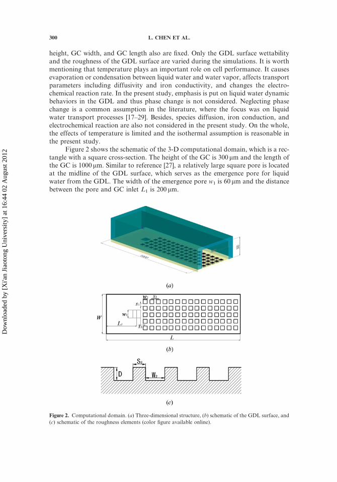
Figure 2 shows the schematic of the 3-D computational domain, which is a rec-tangle with a square cross-section. The height of the GC is 300 mm and the length ofthe GC is 1000 mm. Similar to reference [27], a relatively large square pore is locatedat the midline of the GDL surface, which serves as the emergence pore for liquidwater from the GDL. The width of the emergence pore w1 is 60 mm and the distancebetween the pore and GC inlet L1 is 200 mm.
Figure 2. Computational domain. (a) Three-dimensional structure, (b) schematic of the GDL surface, and
(c) schematic of the roughness elements (color figure available online).
300 L. CHEN ET AL.
Dow
nloa
ded
by [
Xi'a
n Ji
aoto
ng U
nive
rsity
] at
16:
44 0
2 A
ugus
t 201
2

In this study, the roughness of GDL surface is represented by an array of cubicholes distributed on the GDL surface, as shown in Figure 2a. Both the depth D andwidth w1 of the cubic holes are 20 mm. Five cases with different roughness of GDLsurface are considered. Different roughness is obtained by altering the gap betweensquare holes in the flow direction (S2 in Figure 2b). Obviously, a larger gap betweencubic holes indicates lower roughness. The roughness (or roughness factor) of theGDL surface in the present study is defined as follows.
rGDL ¼ 1þ 4S2D=ðS2 þ w2Þ2 ð1Þ
Therefore, the roughness of the GDL for different simulated cases can bequantitatively determined and is listed in Table 2. In Table 2, case 5 is the case witha smooth GDL surface and no hole is arranged on the GDL surface.
In the present studies, cubic holes are only distributed downstream the emerg-ence pore, as this was done in reference [23]. This is because liquid water from theemergence pore can’t move upstream due to the air flow from upstream. Althoughsuch treatment changes the flow field upstream in the GC, the change is believedto be slight and has little effect on liquid water dynamic behaviors in the GC. There-fore, to save computational resources, cubic holes are not arranged upstream theemergence pore.
2.2. Computational Methodology
The two-phase unsteady problems taking place in the computational domaincan be briefly described as follows. Liquid water enters the GC from the emergencepore and gradually grows bigger; since liquid water is subjected to the air flow fromthe GC inlet, it deforms and moves towards the downstream. Due to the lowReynolds number and negligible generated heat, the unsteady two-phase flow isassumed to be isothermal laminar flow without phase change in this study.
The volume of fluid (VOF) method in the commercial CFD package,FLUENT 6.3.26 is employed to simulate the two-phase flow in the GC. An explicitVOF formulation is adopted to track the interface between the liquid water and air.The pressure-implicit with splitting of operators (PISO) scheme is used for thevelocity-pressure coupling. Updating the interface location is achieved by usingthe piecewise linear interface calculation (PLIC) [35]. For a more detailed descriptionof FLUENT 6.3.26 one can refer to reference [36].
Table 2. Simulation cases in this study
Case S1 (mm) S2 (mm) rGDL Contact angle (�)
1 20 20 2 60�, 125�, 145�
2 20 40 1.88 125�, 145�
3 20 60 1.75 125�, 145�
4 20 80 1.64 125�, 145�
5 — — 1 125�, 145�
WATER TRANSPORT IN PROTON EXCHANGE MEMBRANE FUEL CELL 301
Dow
nloa
ded
by [
Xi'a
n Ji
aoto
ng U
nive
rsity
] at
16:
44 0
2 A
ugus
t 201
2

In the VOF method, volume fraction functions Ca and Cw are defined for airand liquid water to track air-liquid water interface. The sum of Ca and Cw in acomputational cell is 1.
Ca þ Cw ¼ 1 ð2Þ
The tracking of the interface is accomplished by solving the following equation ineach computational cell.
qðCwÞqt
þr � ðCwuwÞ ¼ 0 ð3Þ
The governing equations are the continuity and the Navier-Stokes equations.
qðqÞqt
þr � ðquÞ ¼ 0 ð4Þ
qðquÞqt
þr � ðquuÞ ¼ �rpþr � ½mðruþruTÞ� þ qgþ F ð5Þ
where p is the pressure. q and m are volume-averaged density and dynamic viscosity,which are calculated with linear interpolation using the volume fraction function Ck.
q ¼ qaCa þ qwCw ð6Þ
m ¼ maCa þ mwCw ð7Þ
F in Eq. (5) is the force term due to surface tension by adopting the continuum sur-face force (CSF) model [37].
F ¼ 2rkqrCw
ðqa þ qwÞð8Þ
where r is the surface tension coefficient and k is the mean curvature of the interfacewhich is calculated as follows.
k ¼ r � rCw
jrCwj
� �ð9Þ
2.3. Boundary and Initial Conditions
At the left inlet of the GC, air velocity is fixed as 10m s�1. The correspondingRe is about 160 (based on the hydraulic diameter of the channel), which is of thesame order as flow encountered in automotive fuel cell stacks [38]. Besides, similarair velocity is widely used in the literature where liquid water dynamic behaviorsin a micro channel was numerically investigated [23, 27, 28]. At the right exit, fullydeveloped flow is assumed. Liquid water injection rate from the emergence pore isspecified as 1m s�1. For a fuel cell with current density of 1 A cm�2, it’s assumedall the water generated is liquid and the liquid water generation rate is about
302 L. CHEN ET AL.
Dow
nloa
ded
by [
Xi'a
n Ji
aoto
ng U
nive
rsity
] at
16:
44 0
2 A
ugus
t 201
2

9.34� 10�5ml s�1 cm�2. For a reactive area at 10 cm2, the liquid water injection ratespecified here is sufficient to drain all the liquid water from CL through GDL to theGC. It has been reported [27] that within a certain range of Re (50 in their study),liquid water shows similar dynamic behaviors. As dimensions of the micro channeland the emergence pore in the present study is quite similar to that in reference [27],the relatively large liquid water inlet velocity used in reference [27] is also adopted inthe present study to help reduce the simulation time. Using such relatively large inletvelocity, although leads to shorter liquid water removal time, will not change thequalitative results obtained in the present study. Besides, as reported in reference[27], such a liquid water injection rate is of the same order as that used in an ex situfuel cell experiment [39]. The surface tension coefficient between liquid water and airis set as 0.0725N m�1. A hydrophilic GC is adopted because it is beneficial for liquidwater removal and reactants transport [19]. Therefore, the static contact angle is setas 45� between liquid water and two side walls, and between liquid water and the topwall. No slip boundary condition is applied to all the solid walls. The operating tem-perature and pressure are 330K and 101325 Pa, respectively. The convergence criter-ions for all variables are set as 10�6.
2.4. Mesh and Time Step
There are about 101,088 structured orthogonal meshes in the computationaldomain, with the meshes in the cubic holes and the emergence pore refined twice.Figure 3 shows the meshes at x¼ 260mm for case 1. The mesh independency is vali-dated by performing simulations for case 1 with three different mesh sizes. It is foundthat 101,088 meshes are adequate to capture the water behaviors. Simulations withtime steps of 1� 10�7, 5� 10�7, and 5� 10�8 s are also performed for case 1, andno obvious difference is found. Therefore, the time step is set as 1� 10�7 s in thesimulation.
Figure 3. Mesh at x¼ 260mm for case 1.
WATER TRANSPORT IN PROTON EXCHANGE MEMBRANE FUEL CELL 303
Dow
nloa
ded
by [
Xi'a
n Ji
aoto
ng U
nive
rsity
] at
16:
44 0
2 A
ugus
t 201
2

3. RESULTS AND DISCUSSION
Water management inside GC can be optimized by reducing the liquid watercoverage area on the GDL surface, increasing the removal rate of liquid waterand minimizing pressure drop in the GC. Therefore, we focus on the effects of theroughness of the GDL surface on the above three parameters.
3.1. Effects of GDL Surface Wettability
Previous to investigating the effects of surface roughness, the effects of GDLsurface wettability are studied. GDL surface wettability plays a significant role onliquid water behaviors in the GC. The contact angle is commonly used to quantifythe wettability of a solid surface. It is defined as the angle at which the liquid=gasinterface meets the solid surface. If the contact angle is less than 90�, the solid surfaceis hydrophilic and liquid water spreads as film. If the contact angle is greater than90�, the solid surface is hydrophobic and liquid water forms droplets. In this section,simulations are performed for case 1 to investigate liquid water behaviors in GC withhydrophilic and hydrophobic GDL surfaces. The contact angles are set as 60� and145� for the hydrophilic GDL surface and hydrophobic GDL surface, respectively.
Figures 4a and 5a show the liquid water distribution in the GCwith hydrophilicGDL and hydrophobic GDL surfaces, respectively. It can be seen that the liquidwater distribution is quite different. In GC with a hydrophilic GDL surface shownin Figure 4, liquid water tends to spread on the GDL surface. Due to the hydrophilic
Figure 4. Liquid water distribution in GC with hydrophilic GDL at t¼ 4.85ms (case 1, GDL contact
angle¼ 60�). (a) Three-dimensional distribution, and (b) distribution on the GDL surface (color figure
available online).
304 L. CHEN ET AL.
Dow
nloa
ded
by [
Xi'a
n Ji
aoto
ng U
nive
rsity
] at
16:
44 0
2 A
ugus
t 201
2
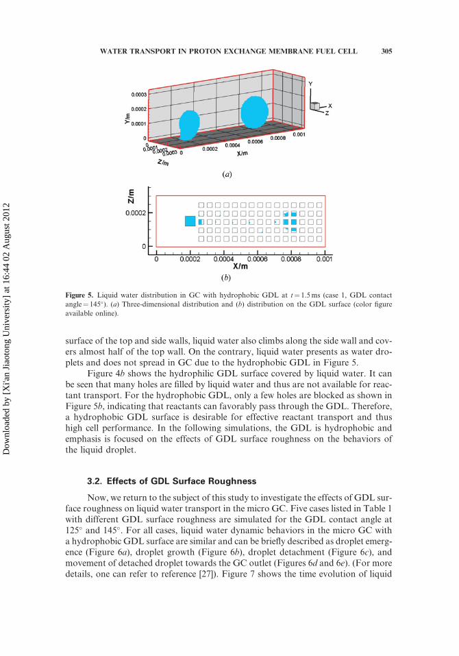
surface of the top and side walls, liquid water also climbs along the side wall and cov-ers almost half of the top wall. On the contrary, liquid water presents as water dro-plets and does not spread in GC due to the hydrophobic GDL in Figure 5.
Figure 4b shows the hydrophilic GDL surface covered by liquid water. It canbe seen that many holes are filled by liquid water and thus are not available for reac-tant transport. For the hydrophobic GDL, only a few holes are blocked as shown inFigure 5b, indicating that reactants can favorably pass through the GDL. Therefore,a hydrophobic GDL surface is desirable for effective reactant transport and thushigh cell performance. In the following simulations, the GDL is hydrophobic andemphasis is focused on the effects of GDL surface roughness on the behaviors ofthe liquid droplet.
3.2. Effects of GDL Surface Roughness
Now, we return to the subject of this study to investigate the effects of GDL sur-face roughness on liquid water transport in the micro GC. Five cases listed in Table 1with different GDL surface roughness are simulated for the GDL contact angle at125� and 145�. For all cases, liquid water dynamic behaviors in the micro GC witha hydrophobic GDL surface are similar and can be briefly described as droplet emerg-ence (Figure 6a), droplet growth (Figure 6b), droplet detachment (Figure 6c), andmovement of detached droplet towards the GC outlet (Figures 6d and 6e). (For moredetails, one can refer to reference [27]). Figure 7 shows the time evolution of liquid
Figure 5. Liquid water distribution in GC with hydrophobic GDL at t¼ 1.5ms (case 1, GDL contact
angle¼ 145�). (a) Three-dimensional distribution and (b) distribution on the GDL surface (color figure
available online).
WATER TRANSPORT IN PROTON EXCHANGE MEMBRANE FUEL CELL 305
Dow
nloa
ded
by [
Xi'a
n Ji
aoto
ng U
nive
rsity
] at
16:
44 0
2 A
ugus
t 201
2

water area fraction Ar at the outlet of GC for different cases with GDL contact angle.Ar is defined as Aw=Aoutlet, where Aw is the area of water at the outlet and Aoutlet is thetotal area of the outlet. Initially, Ar equals 0, implying that the detached water droplethas not arrived at the outlet. As time progresses, Ar undergoes a parabola when theliquid water is passing through the outlet, indicating that liquid water presents as dro-plets for all the simulation cases. Finally,Ar returns to zero when the detached dropletis completely removed out of the GC. Interestingly, Figure 7 shows that curves forcases with a rough GDL surface are different from that for case 5 with smoothGDL, implying that the GDL roughness really affects the liquid water behaviors.Besides, less time is required for a droplet to be completely removed out of the GCwith a rough GDL surface compared with smooth GDL surface, indicating thatrough GDL is advantageous for the removal of a water droplet. In order to betterunderstand howGDL surface roughness affects the removal of a water droplet, forcesacting on a droplet are analyzed in detail in the following section.
3.2.1. Forces acting on a water droplet. The transport process of a dropletin this study involves two stages: droplet growth stage (when the droplet still connectsto the emerging pore, Figures 6a and 6b and the droplet detachment stage (the droplethas detached and moves towards the outlet of the GC, Figures 6c–6e). Obviously,
Figure 6. Time evolution of liquid water behaviors in GC (case 1, GDL contact angle¼ 145�) (color figureavailable online).
306 L. CHEN ET AL.
Dow
nloa
ded
by [
Xi'a
n Ji
aoto
ng U
nive
rsity
] at
16:
44 0
2 A
ugus
t 201
2

liquid water dynamic behaviors in the two stages are combined results of severalforces including shear, pressure, surface tension, gravity, buoyancy, and lift forces.In the present article, a force is called a retentive force if it holds the droplet to theGDL surface or to the emergence pore, whereas a force is called a detaching forceif it tends to detach the droplet from the GDL surface or the emerging pore, or helpsto remove the droplet out of the GC.
Figure 8 schematically shows a droplet suffered to air flow in GC with hydro-phobic GDL. The main forces acting on a droplet when the droplet connects to theemergence pore are schematically shown in Figure 9. These forces are expressed asfollows [40, 41].
Detaching forces
x direction:FP ¼ 24gaUinH
2 R2=b3; pressure forceFs ¼ 24gaUinHR2=b2; shear forcey direction:Fad ¼ prr2=ð2RÞ; surface tension force due to the interfacepressure difference across the water - air surfaceFb ¼ qagV ; buoyancy force
Fl ¼ 0:761ðf qaU2in=2Þ
1:5q�0:5a R3=ga; lift force
8>>>>>>>>>><>>>>>>>>>>:
ð10Þ
Figure 7. Time evolution of liquid water area fraction Ar at the outlet of GC for different cases. (a) GDL
contact angle¼ 125� and (b) GDL contact angle¼ 145� (color figure available online).
Figure 8. Schematic of a water droplet in the GC (color figure available online).
WATER TRANSPORT IN PROTON EXCHANGE MEMBRANE FUEL CELL 307
Dow
nloa
ded
by [
Xi'a
n Ji
aoto
ng U
nive
rsity
] at
16:
44 0
2 A
ugus
t 201
2

Retentive forces
x direction:FR ¼ �rðcos hr � cos haÞpl; surface force due to the water droplet deformationy direction:Fr ¼ �2prr; surface force due to droplet connection to the poreFg ¼ �qwgV ; gravity force
8>>>><>>>>:
ð11Þ
where ta is gas kinematic viscosity, qw is density of water, qa is density of air, and r isthe surface tension of water-air interface. Uin is the inlet air velocity, R is the radiusof the water droplet, r is the radius of the emergence pore, and l is the diameter of thecontact area between liquid water and the GDL surface. ha and hr are the advancingcontact and the receding contact angles, respectively. H is the height of the GC, h isthe height of the liquid water droplet, and b is the height between the top of the drop-let and the top wall of the GC. V is the volume of the water droplet. f for a droplet inGC is defined as 16=Re, and Reynold number Re is Re¼UinH=ta.
After the water droplet detaches from the emergence pore, the bottom of thedroplet contacts the solid surface instead of connecting to the emergence pore. Com-pared to forces acting on the water droplet during the droplet growth process, Fr
vanishes as the droplet no longer connects to the emergence pore. The other forceshave the same expressions as that in the growth process.
In order to roughly estimate the magnitude of the above forces, a typical con-dition is selected with hr as 115�, ha as 155�, and the static contact angle as 145�.Using the physical parameters previously given, forces are calculated and presentedin Figure 10. It can be seen that buoyancy force and gravity force are extremely smallcompared to other forces. Therefore, the influences of the two forces on water drop-let behaviors can be neglected.
In this study, Uin and H are set as constant. As the simulation is performedunder isothermal condition, physical parameters qa, ta, r, and qw also are fixed.
Figure 9. Forces acting on a water droplet (color figure available online).
308 L. CHEN ET AL.
Dow
nloa
ded
by [
Xi'a
n Ji
aoto
ng U
nive
rsity
] at
16:
44 0
2 A
ugus
t 201
2

Therefore, the alterable parameters are b, R, ha, hr, and l. Since forces acting on adroplet are directly related to these alterable parameters, effects of roughness onthese parameters are explored. As the water droplet mainly moves along the flowdirection, i.e., x direction, emphasis is placed on forces which are in the x directionincluding forces Fp, Fs, and FR. It is worth mentioning that liquid water may be liftedfrom the GDL surface and moves in the y direction when the GDL contact angleexceeds certain values [27], which is beyond the scope of the present study.
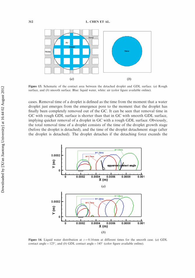
3.2.2. Effects of roughness on Fr, Fp, and Fs. From the expression of FR inEq. (11), it can be seen that FR is the integral around the triple-phase contact line. Inorder to clearly show how the GDL surface roughness affects the triple-phase contactline, liquid water distribution at z¼ 0.14mm at different times for different cases withGDL contact angles at 125� and 145� are given in Figures 11 and 12, respectively. Itcan be seen from the figures that the detached droplet does not fill the holes for allcases. Instead, it moves on the top surface of the holes. Generally, a droplet on a roughsurface can be described by two models: namely, the Wenzel [42] and Cassie andBaxter models [43]. The Wenzel’s model assumes that liquid wets and fills the roughsurface completely. On the contrary, the Cassie and Baxter model assumes that theliquid water doesn’t fill the rough surface, and the interface between the liquid waterand rough surface is composed of both solid and gas. As can be seen in Figures 11 and12, liquid water sits on the top surface of the roughness elements and air is trapped inthe hole which meets the Cassie and Baxter model. Thus, the detached droplet can becalled a Cassie droplet. Compared to the contact area between a water droplet andsmooth GDL surface, the contact area between the Cassie droplet and the roughGDL surface consists of air-water and water-solid interfaces (schematically shownin Figure 13), leading to a discontinuous triple-phase contact line. Therefore, thetriple-phase contact line on the rough GDL surface is shorter than that on the smoothGDL surface, resulting in lower FR and thus smaller retentive force. For the contact
Figure 10. Forces acting on a water droplet on a smooth surface as a function of water droplet size (color
figure available online).
WATER TRANSPORT IN PROTON EXCHANGE MEMBRANE FUEL CELL 309
Dow
nloa
ded
by [
Xi'a
n Ji
aoto
ng U
nive
rsity
] at
16:
44 0
2 A
ugus
t 201
2

area between a water droplet and rough GDL surface at 125� with a radius of about70 mm (shown in Figure 13a), the triple-phase contact line is only about 50% of that onthe smooth GDL surface, leading to considerably reduced FR.
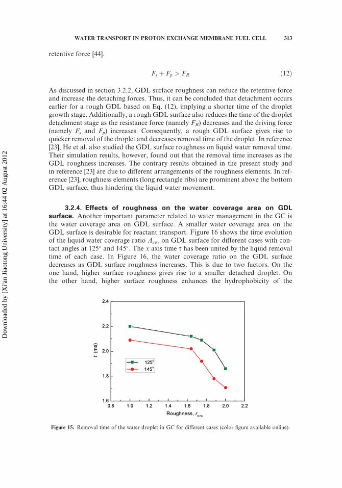
In order to compare the water distribution in GC with a rough GDL surface tothat in GCwith a smooth GDL surface, water distribution in GCwith a smooth GDLsurface (case 5) is also presented (as shown in Figure 14). It is clearly shown that theapparent contact angle (the appeared contact angle labeled in Figure 14a) on therough GDL is higher than that on the smooth surface, although the initially given sta-tic contact angle is the same. This is expected because surface roughness can enhancethe hydrophobicity of the rough surface [43]. A higher apparent contact angle givesrise to the following impacts on forces. On the one hand, for the same water droplet
Figure 11. Liquid water distribution at z¼ 0.14mm at different times for different cases with a GDL
contact angle as 125�. (a) Case 1, (b) case 2, (c) case 3, and (d) case 4 (color figure available online).
310 L. CHEN ET AL.
Dow
nloa
ded
by [
Xi'a
n Ji
aoto
ng U
nive
rsity
] at
16:
44 0
2 A
ugus
t 201
2
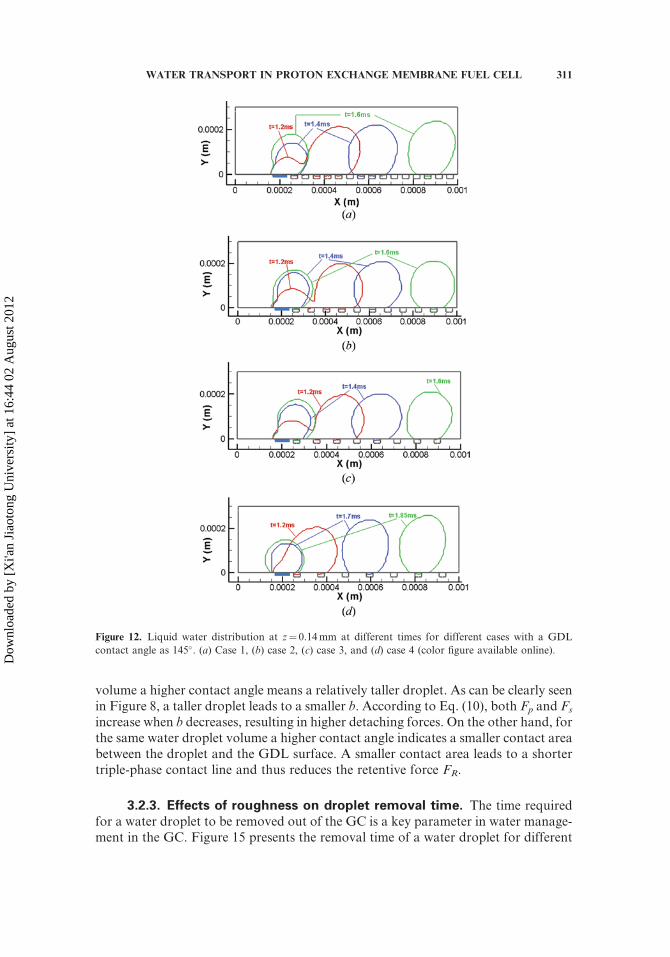
volume a higher contact angle means a relatively taller droplet. As can be clearly seenin Figure 8, a taller droplet leads to a smaller b. According to Eq. (10), both Fp and Fs
increase when b decreases, resulting in higher detaching forces. On the other hand, forthe same water droplet volume a higher contact angle indicates a smaller contact areabetween the droplet and the GDL surface. A smaller contact area leads to a shortertriple-phase contact line and thus reduces the retentive force FR.
3.2.3. Effects of roughness on droplet removal time. The time requiredfor a water droplet to be removed out of the GC is a key parameter in water manage-ment in the GC. Figure 15 presents the removal time of a water droplet for different
Figure 12. Liquid water distribution at z¼ 0.14mm at different times for different cases with a GDL
contact angle as 145�. (a) Case 1, (b) case 2, (c) case 3, and (d) case 4 (color figure available online).
WATER TRANSPORT IN PROTON EXCHANGE MEMBRANE FUEL CELL 311
Dow
nloa
ded
by [
Xi'a
n Ji
aoto
ng U
nive
rsity
] at
16:
44 0
2 A
ugus
t 201
2
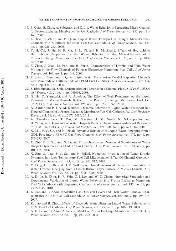
cases. Removal time of a droplet is defined as the time from the moment that a waterdroplet just emerges from the emergence pore to the moment that the droplet hasfinally been completely removed out of the GC. It can be seen that removal time inGC with rough GDL surface is shorter than that in GC with smooth GDL surface,implying quicker removal of a droplet in GC with a rough GDL surface. Obviously,the total removal time of a droplet consists of the time of the droplet growth stage(before the droplet is detached), and the time of the droplet detachment stage (afterthe droplet is detached). The droplet detaches if the detaching force exceeds the
Figure 14. Liquid water distribution at z¼ 0.14mm at different times for the smooth case. (a) GDL
contact angle¼ 125�, and (b) GDL contact angle¼ 145� (color figure available online).
Figure 13. Schematic of the contact area between the detached droplet and GDL surface. (a) Rough
surface, and (b) smooth surface. Blue: liquid water, white: air (color figure available online).
312 L. CHEN ET AL.
Dow
nloa
ded
by [
Xi'a
n Ji
aoto
ng U
nive
rsity
] at
16:
44 0
2 A
ugus
t 201
2
retentive force [44].
Fs þ Fp > FR ð12Þ
As discussed in section 3.2.2, GDL surface roughness can reduce the retentive forceand increase the detaching forces. Thus, it can be concluded that detachment occursearlier for a rough GDL based on Eq. (12), implying a shorter time of the dropletgrowth stage. Additionally, a rough GDL surface also reduces the time of the dropletdetachment stage as the resistance force (namely FR) decreases and the driving force(namely Fs and Fp) increases. Consequently, a rough GDL surface gives rise toquicker removal of the droplet and decreases removal time of the droplet. In reference[23], He et al. also studied the GDL surface roughness on liquid water removal time.Their simulation results, however, found out that the removal time increases as theGDL roughness increases. The contrary results obtained in the present study andin reference [23] are due to different arrangements of the roughness elements. In ref-erence [23], roughness elements (long rectangle ribs) are prominent above the bottomGDL surface, thus hindering the liquid water movement.
3.2.4. Effects of roughness on the water coverage area on GDLsurface. Another important parameter related to water management in the GC isthe water coverage area on GDL surface. A smaller water coverage area on theGDL surface is desirable for reactant transport. Figure 16 shows the time evolutionof the liquid water coverage ratio Acov on GDL surface for different cases with con-tact angles at 125� and 145�. The x axis time s has been united by the liquid removaltime of each case. In Figure 16, the water coverage ratio on the GDL surfacedecreases as GDL surface roughness increases. This is due to two factors. On theone hand, higher surface roughness gives rise to a smaller detached droplet. Onthe other hand, higher surface roughness enhances the hydrophobicity of the
Figure 15. Removal time of the water droplet in GC for different cases (color figure available online).
WATER TRANSPORT IN PROTON EXCHANGE MEMBRANE FUEL CELL 313
Dow
nloa
ded
by [
Xi'a
n Ji
aoto
ng U
nive
rsity
] at
16:
44 0
2 A
ugus
t 201
2

GDL surface, and thus decreases the contact area between the droplet bottom andthe GDL surface.
3.2.5. Effects of roughness on pressure drop. Pressure drop in the GC isanother important parameter for fuel cell design. Compared to two-phase flow inGC with a smooth GDL surface, pressure drop in GC with a rough GDL surfacewill change due to two factors: one is the existence of roughness elements, and theother is the change of droplet shapes due to the surface roughness. First, forsingle-phase in micro-scale channels, surface roughness, even very small, will sig-nificantly influence the friction factor [45, 46]. Mala and Li [45] reported thatthe pressure drop in micro-channels is higher than the predictions using conven-tional theory. Shen et al. [46] experimentally studied single-phase convective heattransfer in rough rectangular micro-channels. They found that friction factor inthe regime of higher Re is higher than the predictions using conventional theoryand increases with increasing Re instead of keeping constant. Second, fortwo-phase flow in micro-channels, surface roughness significantly affects the flowpatterns, which certainly affects the pressure drop. In this study, the surface rough-ness gives rise to a taller detached droplet, as discussed in section 3.2.2. Figure 17shows the pressure drop for different cases with contact angles at 125� and 145�.The pressure drop in the figure is an averaged value by the removal time. It canbe observed that pressure drop increases with the increasing GDL surface rough-ness, which is due to the increased roughness and the increasingly taller droplet forhigher roughness.
Finally, it may be useful to note that in our paper the characteristic of the sur-face structure of the GDL is described by the terminology of roughness. This maynot be the most accurate description of the surface character of the GDL, but it isaccepted in reference [23] studying effects of GDL microstructures on liquid waterbehaviors, and is also widely used in other fields where liquid water movements ona surface with microstructures are considered [47–49]. From our understanding,although the GDL is something like a porous medium when the movement of awater droplet over the surface of GDL is concerned, its effects on the drop
Figure 16. Time evolution of water coverage ratio on a GDL surface for different cases. (a) GDL contact
angle¼ 125�, and (b) GDL contact angle¼ 145� (color figure available online).
314 L. CHEN ET AL.
Dow
nloa
ded
by [
Xi'a
n Ji
aoto
ng U
nive
rsity
] at
16:
44 0
2 A
ugus
t 201
2

movement are actually very similar to a roughened surface. In addition, the poresize and porosity adopted in our simulation (20 mm and about 0.5, respectively)are quite close to the typical values of a carbon paper GDL (pore size 1-100 mmand porosity about 0.8, which will be reduced if a hydrophobic agent PTFE isadded). The surface structure reconstructed based on such dimensions (Figure 2)may be regarded as a surface with micro-roughness.
4. CONCLUSION
In this study, liquid water transport in a micro GC with a rough GDL surfaceis investigated. Effects of GDL surface roughness on forces acting on a water dropletare carefully explored. Effects of GDL surface roughness on liquid water removaltime, liquid water coverage area ratio on GDL surface, and pressure drop in theGC also are studied. The main conclusions are derived as follows.
. A Cassie droplet is inclined to form in the micro GC with rough and hydrophobicGDL surfaces. The GDL surfaces roughness increases the apparent contact anglebetween the droplet and GDL surface, and decreases the triple-phase contact line.Thus, the GDL surface roughness leads to lower retentive forces and higherdetaching forces acting on the water droplet.
. The GDL surface roughness accelerates the removal of a droplet. The higher theroughness is, the less the removal time.
. The GDL surface roughness reduces the water coverage ratio on the GDL surfacebecause the roughness enhances the surface hydrophobicity. The rougher the sur-face is, the less the GDL surface is covered by water.
. The GDL surface roughness increases the pressure drop in the GC. The rougherthe surface is, the higher the pressure drop is.
Figure 17. Averaged pressure drop for different cases (color figure available online).
WATER TRANSPORT IN PROTON EXCHANGE MEMBRANE FUEL CELL 315
Dow
nloa
ded
by [
Xi'a
n Ji
aoto
ng U
nive
rsity
] at
16:
44 0
2 A
ugus
t 201
2

REFERENCES
1. H. Li, Y. Tang, Z. Wang, Z. Shi, S. Wu, D. Song, J. Zhang, K. Fatih, J. Zhang, H. Wang,Z. Liu, R. Abouatallah, and A. Mazza, A Review of Water Flooding Issues in the ProtonExchange Membrane Fuel Cell, J. of Power Sources, vol. 178, no. 1, pp. 103–117, 2008.
2. A. Bazylak, Liquid Water Visualization in PEM Fuel Cells: A Review, Int. J. of HydrogenEnergy, vol. 34, no. 9, pp. 3845–3857, 2009.
3. R. Anderson, L. Zhang, Y. Ding, M. Blanco, X. Bi, and D. P. Wilkinson, A CriticalReview of Two-Phase Flow in Gas Flow Channels of Proton Exchange Membrane FuelCells, J. of Power Sources, vol. 195, no. 15, pp. 4531–4553, 2010.
4. F. Y. Zhang, X. G. Yang, and C. Y. Wang, Liquid Water Removal from a PolymerElectrolyte Fuel Cell, J. of the Electrochemical Society, vol. 153, no. 2, pp. A225–A232,2006.
5. J. P. Owejan, T. A. Trabold, D. L. Jacobson, D. R. Baker, D. S. Hussey, and M. Arif, InSitu Investigation of Water Transport in an Operating PEM Fuel Cell using NeutronRadiography: Part 2—Transient Water Accumulation in an Interdigitated Cathode FlowField, Int. J. of Heat and Mass Transfer, vol. 49, no. 25–26, pp. 4721–4731, 2006.
6. T. Ous and C. Arcoumanis, Visualisation of Water Accumulation in the Flow Channelsof PEMFC under Various Operating Conditions, J. of Power Sources, vol. 187, no. 1,pp. 182–189, 2009.
7. N. Pekula, K. Heller, P. A. Chuang, A. Turhan, M. M. Mench, J. S. Brenizer, andK. Unlu, Study of Water Distribution and Transport in a Polymer Electrolyte Fuel Cellusing Neutron Imaging, Nuclear Instruments and Methods in Physics Research Section A:Accelerators, Spectrometers, Detectors and Associated Equipment, vol. 542, no. 1–3, pp.134–141, 2005.
8. D. Spernjak, A. K. Prasad, and S. G. Advani, In Situ Comparison of Water Content, andDynamics in Parallel, Single-Serpentine, and Interdigitated Flow Fields of Polymer Elec-trolyte Membrane Fuel Cells, J. of Power Sources, vol. 195, no. 11, pp. 3553–3568, 2011.
9. J. P. Owejan, T. A. Trabold, D. L. Jacobson, M. Arif, and S. G. Kandlikar, Effects ofFlow Field and Diffusion Layer Properties on Water Accumulation in a PEM Fuel Cell,Int. J. of Hydrogen Energy, vol. 32, no. 17, pp. 4489–4502, 2007.
10. A. Turhan, K. Heller, J. S. Brenizer, and M. M. Mench, Passive Control of Liquid WaterStorage and Distribution in a PEFC Through Flow-Field Design, J. of Power Sources,vol. 180, no. 2, pp. 773–783, 2008.
11. A. Turhan, S. Kim, M. Hatzell, and M. M. Mench, Impact of Channel Wall Hydropho-bicity on Through-Plane Water Distribution and Flooding Behavior in a Polymer Electro-lyte Fuel Cell, Electrochimica Acta, vol. 55, no. 8, 2734–2745, 2010.
12. Z. H. Wang, C. Y. Wang, and K. S. Chen, Two-Phase Flow and Transport in the AirCathode of Proton Exchange Membrane Fuel Cells, J. of Power Sources, vol. 94, no. 1,pp. 40–50, 2001.
13. L. You and H. Liu, A Two-Phase Flow and Transport Model for the Cathode of PEMFuel Cells, Int. J. of Heat and Mass Transfer, vol. 45, no. 11, pp. 2277–2287, 2002.
14. T. Berning and N. Djilali, Three-Dimensional Computational Analysis of TransportPhenomena in a PEM Fuel Cell–a Parametric Study, J. of Power Sources, vol. 124,no. 2, pp. 440–452, 2003.
15. V. Gurau, J. A. Mann, and T. A. Zawodzinski, Two-Phase Transport in PEM Fule CellCathodes, J. of Fuel Cell Sicence and Tech., vol. 5, (021009–1-021009–12), 2008.
16. V. Gurau and J. A. Mann, Effect of Interfacial Phenomena at the Gas DiffusionLayer-Channel Interface on the Water Evolution in a PEMFC, J. of the ElectrochemicalSociety, vol. 157, no. 4, pp. B512–B521, 2010.
316 L. CHEN ET AL.
Dow
nloa
ded
by [
Xi'a
n Ji
aoto
ng U
nive
rsity
] at
16:
44 0
2 A
ugus
t 201
2
17. P. Quan, B. Zhou, A. Sobiesiak, and Z. Liu, Water Behavior in Serpentine Micro-Channelfor Proton Exchange Membrane Fuel Cell Cathode, J. of Power Sources, vol. 152, pp. 131–145, 2005.
18. K. Jiao, B. Zhou, and P. Quan, Liquid Water Transport in Straight Micro-Parallel-Channels with Manifolds for PEM Fuel Cell Cathode, J. of Power Sources, vol. 157,no. 1, pp. 226–243, 2006.
19. Y. H. Cai, J. Hu, H. P. Ma, B. L. Yi, and H. M. Zhang, Effects of Hydrophilic=Hydrophobic Properties on the Water Behavior in the Micro-Channels of aProton Exchange Membrane Fuel Cell, J. of Power Sources, vol. 161, no. 2, pp. 843–848, 2006.
20. Z. Zhan, J. Xiao, M. Pan, and R. Yuan, Characteristics of Droplet and Film WaterMotion in the Flow Channels of Polymer Electrolyte Membrane Fuel Cells, J. of PowerSources, vol. 160, no. 1, pp. 1–9, 2006.
21. K. Jiao, B. Zhou, and P. Quan, Liquid Water Transport in Parallel Serpentine Channelswith Manifolds on Cathode Side of a PEM Fuel Cell Stack, J. of Power Sources, vol. 154,no. 1, pp. 124–137, 2006.
22. S. Ebrahim and M. Shila, Deformation of a Droplet in a Channel Flow, J. of Fuel Cell Sci.and Techn., vol. 5, no. 4, pp. 041008, 2008.
23. G. He, Y. Yamazaki, and A. Abudula, The Effect of Wall Roughness on the LiquidRemoval in Micro-Channels Related to a Proton Exchange Membrane Fuel Cell(PEMFC), J. of Power Sources, vol. 195, no. 6, pp. 1561–1568, 2010.
24. N. Akhtar and P. J. A. M. Kerkhof, Dynamic Behavior of Liquid Water Transport in aTapered Channel of a Proton Exchange Membrane Fuel Cell Cathode, Int. J. of HydrogenEnergy, vol. 36, no. 4, pp. 3076–3086, 2011.
25. A. Theodorakakos, T. Ous, M. Gavaises, J. M. Nouri, N. Nikolopoulos, andH. Yanagihara, Dynamics ofWater Droplets Detached from Porous Surfaces of Relevanceto PEM Fuel Cells, J. of Colloid and Interface Sci., vol. 300, no. 2, pp. 673–687, 2006.
26. X. Zhu, P. C. Sui, and N. Djilali, Dynamic Behaviour of Liquid Water Emerging from aGDL Pore into a PEMFC Gas Flow Channel, J. of Power Sources, vol. 172, no. 1, pp.287–295, 2007.
27. X. Zhu, P. C. Sui, and N. Djilali, Three-Dimensional Numerical Simulations of WaterDroplet Dynamics in a PEMFC Gas Channel, J. of Power Sources, vol. 181, no. 1, pp.101–115, 2008.
28. X. Zhu, Q. Liao, P. C. Sui, and N. Djilali, Numerical Investigation of Water DropletDynamics in a Low-Temperature Fuel Cell Microchannel: Effect Of Channel Geometry,J. of Power Sources, vol. 195, no. 3, pp. 801–812, 2010.
29. Y. Ding, H. T. Bi, and D. P. Wilkinson, Three-Dimensional Numerical Simulation ofWater Droplet Emerging from a Gas Diffusion Layer Surface in Micro-Channels, J. ofPower Sources, vol. 195, no. 21, pp. 7278–7288, 2010.
30. A. D. Le, B. Zhou, H.-R. Shiu, C.-I. Lee, and W.-C. Chang, Numerical Simulation andExperimental Validation of Liquid Water Behaviors in a Proton Exchange MembraneFuel Cell Cathode with Serpentine Channels, J. of Power Sources, vol. 195, no. 21, pp.7302–7315, 2010.
31. K. Jiao and B. Zhou, Innovative Gas Diffusion Layers and Their Water Removal Char-acteristics in PEM Fuel Cell Cathode, J. of Power Sources, vol. 169, no. 2, pp. 296–314,2007.
32. K. Jiao and B. Zhou, Effects of Electrode Wettabilities on Liquid Water Behaviours inPEM Fuel Cell Cathode, J. of Power Sources, vol. 175, no. 1, pp. 106–119, 2008.
33. A. D. Le and B. Zhou, A General Model of Proton Exchange Membrane Fuel Cell, J. ofPower Sources, vol. 182, no. 1, pp. 197–222, 2008.
WATER TRANSPORT IN PROTON EXCHANGE MEMBRANE FUEL CELL 317
Dow
nloa
ded
by [
Xi'a
n Ji
aoto
ng U
nive
rsity
] at
16:
44 0
2 A
ugus
t 201
2
34. A. D. Le and B. Zhou, A Generalized Numerical Model for Liquid Water in a ProtonExchange Membrane Fuel Cell with Interdigitated Design, J. of Power Sources, vol.
193, no. 2, pp. 665–683, 2009.35. D. L. Youngs, Numerical Methods for Fluid Dynamics, Academic Press: New York, 1982.36. Fluent 6.3 User’s Guide, Fluent Inc., 2006.37. J. U. Brackbill, D. B. Kothe, and C. Zemach, A ContinuumMethod for Modeling Surface
Tension, J. of Computational Physics, vol. 100, no. 2, pp. 335–354, 1992.38. P. C. Sui and N. Djilali, Analysis of Water Transport in Proton Exchange Membranes
Using a Phenomenological Model, ASME J. of Fuel Cell Sci. and Techn., vol. 2, no. 3,pp. 149–155, 2005.
39. A. Bazylak, D. Sinton, Z. S. Liu, and N. Djilali, Effect of Compression on Liquid WaterTransport and Microstructure of PEMFC Gas Diffusion Layers, J. of Power Sources, vol.163, no. 2, pp. 784–792, 2007.
40. Z. Wang and S. C. Wang, Effect of Continuous Phase Viscosity on Membrane Emulsifi-cation, Chin. J. Chem. Eng., vol. 8, pp. 108–112, 2002.
41. G. D. Luca, A. Sindona, L. Giorno et al. Quantitative Analysis of Coupling Effects inCross-Flow Membrane Emulsification, J. Membr. Sci., vol. 29, pp. 199–209, 2004.
42. R. N. Wenzel, Resistance of Solid Surface to Wetting by Water, Industrial and Engi.chem., vol. 28, pp. 988–994, 1936.
43. A. B. D. Cassie and S. Baxter, Wettability of Porous Surfaces, Trans. of the FaradaySociety, vol. 40, pp. 546–551, 1994.
44. E. C. Kumbur, K. V. Sharp, and M. M. Mench, Liquid Droplet Behavior and Instabilityin a Polymer Electrolyte Fuel Cell Flow Channel, J. of Power Sources, vol. 161, no. 1, pp.333–345, 2006.
45. G. Mohiuddin Mala and D. Li, Flow Characteristics of Water in Microtubes, Int. J. ofHeat and Fluid Flow, vol. 20, no. 2, pp. 142–148, 1999.
46. S. Shen, J. L. Xu, J. J. Zhou, and Y. Chen, Flow and Heat Transfer in Microchannelswith Rough Wall Surface, Energy Conversion and Management, vol. 47, no. 11–12, pp.1311–1325, 2006.
47. Z. Yoshimitsu, A. Nakajima, T. Watanabe, and K. Hashimoto, Effects of Surface Struc-ture on the Hydrophobicity and Sliding Behavior of Water Droplets, Langmuir, vol. 18,no. 15, pp. 5818–5822, 2002.
48. B. He, N. A. Patankar, and J. Lee, Multiple Equilibrium Droplet Shapes and DesignCriterion for Rough Hydrophobic Surfaces, Langmuir, vol. 19, no. 12, pp. 4999–5003,2003.
49. C. Sun, X.-W. Zhao, Y.-H. Han, and Z.-Z. Gu, Control of Water Droplet Motion byAlteration of Roughness Gradient on Silicon Wafer by Laser Surface Treatment, ThinSolid Films, vol. 516, no. 12, pp. 4059–4063, 2008.
318 L. CHEN ET AL.
Dow
nloa
ded
by [
Xi'a
n Ji
aoto
ng U
nive
rsity
] at
16:
44 0
2 A
ugus
t 201
2