effects of variable loading conditions on the dynamic
TRANSCRIPT

1
Effects of variable loading conditions on the dynamic
behaviour of planetary gear with power recirculation
Ahmed Hammami1,2
, Alfonso Fernandez Del Rincon2, Fakher Chaari
1, Miguel Iglesias
Santamaria2,Fernando Viadero Rueda
2, Mohamed Haddar
1
1Mechanics, Modeling and Production Laboratory- National School of Engineers Sfax
BP 1173 – 3038 – Sfax – Tunisia 2Department of Structural and Mechanical Engineering - Faculty of Industrial and
Telecommunications Engineering - University of Cantabria - Avda. de los Castros s/n - 39005
Santander- Spain.
[email protected],[email protected],
[email protected],[email protected],[email protected],
Abstract
Variable loads to which gearboxes are subjected are considered as one of the main sources of non-
stationarity in these transmissions. In order to characterise their dynamic behaviour in such conditions,
a torsional lumped parameter model of a planetary gear with power recirculation was developed. The
model included time varying loading conditions and took into account the non-linearity of contact
between teeth. The meshing stiffness functions were modelled using Finite Element Method and
Hertzian contact theory in these conditions. Series of numerical simulations was conducted in
stationary conditions, with different loading conditions. Equation of motion was solved using
Newmark algorithm. Numerical results agreed with experimental results obtained from a planetary
gear test bench. This test bench is composed of two similar planetary gears called test planetary gear
set and reaction planetary gear set which are mounted back-to-back so that the power recirculates
through the transmission. The external load was applied through an arm attached to the free reaction
ring. Data Acquisition System acquired signals from accelerometers mounted on the rings and
tachometer which measured instantaneous angular velocity of the carrier’s shaft. The signal processing
was achieved using LMS Test.Lab software. Modulation sidebands were obtained from the ring
acceleration measurements as well as a non-linear behaviour in case of variable loading resulted by a
transfer of the spectral density from the fundamental mesh stiffness to its second harmonic.
Keywords back-to-back planetary gears, variable load, dynamic behaviour

2
1. Introduction
The use of planetary gears in industrial applications is justified by their ability to transmit high
torques with substantial ranges of speed reduction. Many industrial applications use this kind of
transmissions such as aircraft engines, wind turbines, ...
Several studies were devoted mostly to planetary gears running under constant speed and load i.e.
in stationary conditions [1-5]. However, it is possible to find industrial applications involving
planetary gears where both load and speed are time varying. Severe non-stationary conditions may
lead to excessive vibrations and instability [6].
McFadden and Smith [1] focused on the modulating sidebands around meshing frequency and
harmonics caused by non-stationary conditions. Al-shyyab and Kahraman [2] implemented multi-term
harmonic balance methodology on a nonlinear torsional model of a single stage planetary gear in order
to solve the equations of motion. Inalpolat [3] developed a numerical model to predict modulation
sidebands, he described the mechanisms causing sidebands and he validated experimentally the
obtained numerical results. He also studied amplitude and frequency modulations caused by
manufacturing errors of gears and estimated dynamic loads on sun-planet and ring-planet gear meshes
[4]. Liu et al. [5] took into account in their dynamic model variable transmission path of vibration in
planetary gears and validated their work experimentally.
Concerning studies devoted to variable loading conditions, it seems that Randall [7] was the first to
relate load fluctuation to vibration level. Chaari [8] proposed a bi-dimensional model of a spur
planetary gear subjected to both time varying load and speed and highlighted corresponding amplitude
and frequency modulations. Mark [9] was interested in the variability of load transmission from one
planet to the other caused by imperfections in the transmission. He also focused on vibration spectra
shapes of signals registered by fixed-accelerometer for the case of a cracked planet-carrier plate that
caused variability in load transfer through planets. Mark [10] extended his studies to the influence of
planet–carrier vibration signals modulations on the computed spectra. Feng [11] considered, in his
dynamic model of planetary gear, the effect of distributed and localized gear faults on amplitude and
frequency modulation effects observed in vibration signals. Lei [12] implemented the adaptive
stochastic resonance method for a planetary gearbox having a chipped and missing sun gear tooth.
Bartelmus and Zimroz [13] showed that planetary gearbox running in bad conditions is more
susceptible to external load than planetary gearbox running in good conditions. They introduced a new
diagnostic feature which is used for monitoring the condition of planetary gearboxes under varying
external load conditions [14]. Kim [15] was interested in the influence of time varying pressure angles
and contact ratios on the dynamic behaviour of planetary gear. In all these cited woks, the varying
external load caused a variation of speed in the studied systems.
Complex planetary gearboxes received great interest by scientists. Ligata et al. [16] studied on a
back-to-back planetary gear system the influence of manufacturing defects on stresses in the tooth
roots and on the load sharing between planets. Singh et al. [17] focused on the impact of changing

3
parameters of multistage planetary gearbox on stresses in gear teeth and on load sharing through
numerical and experimental investigations. Hammami et al. [18] was interested in the modal
characteristics of back-to-back planetary gear set by computing modal kinetic and strain energy
distributions. In addition, they [19] achieved a series of experimental tests for run up and run down
regimes of the same gearbox in order to validate the modal analysis and to study its dynamic
behaviour in non-stationary conditions.
This paper is dedicated to the study of the dynamic behaviour of a complex planetary gearbox
running in another non-stationary operation which is the time varying loading condition with the
specifications of an imposed constant speed. To achieve this target, a back-to-back planetary gearbox
with mechanical power recirculation set up was characterized as the load was applied by the external
arm. First, a dynamic model of planetary gear set with power recirculation will be developed.
Modulation sidebands will be highlighted in stationary condition in the case of equally-spaced planets
and sequentially phased gear meshes. Then, different loading conditions will be considered to show
the non linear behaviour of the studied gearbox and to explain its behaviour in the variable loading
conditions which is presented in the last section. Simulation and experimental studies for this gear
system will be presented and correlated in all studied conditions.
2. Material and methods
The test bench used in this research work is composed of two similar planetary gears mounted
back-to-back so that the power recirculates through the transmission. This special configuration is
selected in order to minimize costs and improve energy efficiency. Figure 1 shows a general scheme of
the studied transmission.
Fig.1: Test bench scheme
The two planetary gear sets are named respectively test gear set and reaction gear set. The main
planetary gear set is the test gear set where its output power from its carrier is reintroduced to its sun

4
through the reaction planetary gear set. They are connected in back-to-back configuration. Sun gears
are mounted on the same shaft and the carriers are connected by a hollow shaft.
In order to introduce external load, mass is added on an arm attached to reaction gear. The test gear
ring is clamped (Fig.3). The direction of rotation is such that the friction torque always adds to the
reaction ring gear applied torque.
The transmission is driven by an asynchronous motor to which a speed controller is added in order
to impose desired speed evolution and values. Accelerations on rings are measured by two tri-axial
accelerometers (Fig.2 and Fig.3).
An optical tachometer combined with pulse tapes is mounted on the hollow shaft in order to
measure instantaneous angular velocity.
LMS SCADAS 316 Data Acquisition System acquires signals from tachometer and accelerometers
and the signal processing is achieved using LMS Test.Lab software.
Fig.2: Instrumentation of the test bench
Drive
motor
Reaction gear set Test gear set
Tachometer
Strip Band
LMS 316
Acelerometers

5
Fig.3: Sensors and external load
International standard “ISO 6336” [20- 23] allows to determine the minimum tangential torque on
the reaction ring that will produce the mechanical failure in case of tooth bending and pitting for the
different gear components of the system. These limits are presented in table 1.
Table 1. Minimum torque that produce failure
Contact Component
Torque producing
Bending (N.m)
Torque producing Pitting
(N.m)
Sun-Planet Sun 2644 1100
Planet 3630 1100
Ring-Planet Planet 2411 1650
Ring 47587 9446
In order to avoid bending and pitting defect, applied torques on the test rig will not exceed
1100 Nm.
Optical tachometer
Tri axial accelerommeters
on the reaction ring
Tri axial accelerometers on
the test ring Added
mass
Arm
6
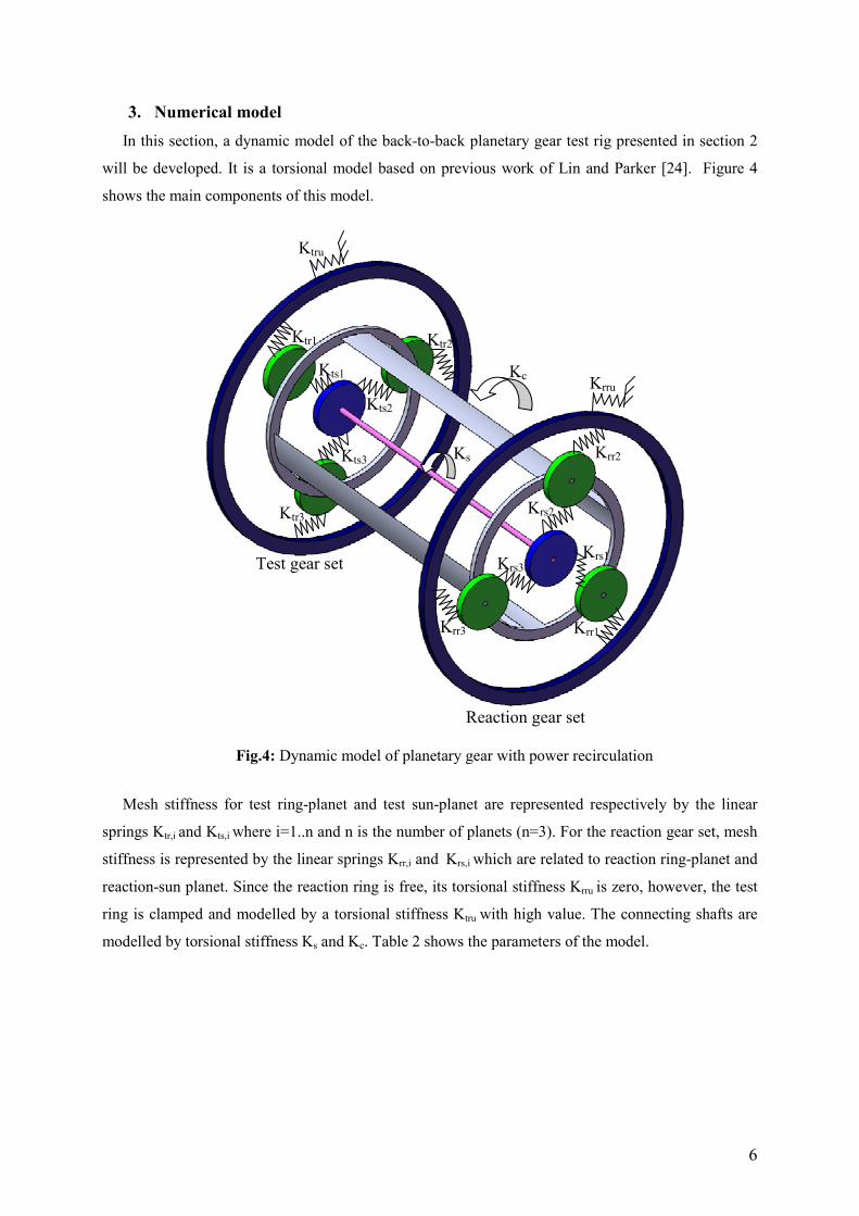
3. Numerical model
In this section, a dynamic model of the back-to-back planetary gear test rig presented in section 2
will be developed. It is a torsional model based on previous work of Lin and Parker [24]. Figure 4
shows the main components of this model.
Mesh stiffness for test ring-planet and test sun-planet are represented respectively by the linear
springs Ktr,i and Kts,i where i=1..n and n is the number of planets (n=3). For the reaction gear set, mesh
stiffness is represented by the linear springs Krr,i and Krs,i which are related to reaction ring-planet and
reaction-sun planet. Since the reaction ring is free, its torsional stiffness Krru is zero, however, the test
ring is clamped and modelled by a torsional stiffness Ktru with high value. The connecting shafts are
modelled by torsional stiffness Ks and Kc. Table 2 shows the parameters of the model.
Fig.4: Dynamic model of planetary gear with power recirculation
Krru
Ktru
Krr1
Krr2
Krr3
Krs2
Krs1 Krs3
Kc
Kts2
Kts3
Kts1
Ktr1 Ktr2
Ktr3
Ks
Reaction gear set
Test gear set

7
Table 2. Parameters of the system
Planetary gears
Sun Planet Ring Carrier
Teeth number 16 24 65 -
Mass (Kg) 0.48 1.2 28 3.6
Base diameter (mm) 61.3 92.0 249.3 57.5
Moment of inertia (Kg.m²) 350 × 10-6 2050 × 10
-6 697770 × 10-6 21500 × 10
-6
Torsional stiffness Nm/rd
(test set) 3 x 10
8
Torsional stiffness (Nm/rd)
(Reaction set) 0
Shaft stiffness
Sun Planet Ring Carrier
Torsional (Nm/rad) 9.3 × 10⁷ - - 3.7 × 10
8
Non floating Suns and planets are considered and only rotational motions of the gear bodies are
considered [25]. The equation of motion of the system with 3 planets can be written as:
( )tFXKtKXCXM c =+++ ))((&&& (1)
Where M is the mass matrix. )(tK is the stiffness matrix, cK is the coupling shaft stiffness matrix
and ( )tF is the external force vector applied to the system.
It is possible to decompose )(tK into a mean stiffness matrix K~
and a time varying matrix )(tk :
)(~
)( tkKtK += (2)
C is the Rayleigh damping matrix expressed by [26]:
KMC~
βα += (3)
Where α and β are two constants [26] expressed by s5
10.5−=α and 15.410.5 −−= sβ
.
All the matrices are defined in the appendix of [19].
X is the degree of freedom vector expressed by :
{ }Tttttstrtcrrrrsrrrc xxxxxxxxxxxxX 321321 ,,,,,,,,,,,= (4)
The rotational coordinates are computed by jrjrjr rx θ= for reaction gear set and by jtjtjt rx θ= for
test gear set (j=c,r,s,1,2,3). jrθ and jtθ are the rotational components; jrr and jtr are the base radius for
the sun, ring and planets and the radius of the circle passing through the planets centres for the carrier.
In order to compute the solution of the problem, implicit Newmark algorithm is used.

8
4. Results and discussion
Two kinds of simulations and experimental studies will be carried out. In the first one, stationary
condition will be considered. Then, time varying loading conditions is applied to the system. Results
from simulations and experiments will be compared.
4.1. Stationary conditions
Three equally-spaced planets are considered for each planetary gear. They are positioned at
angles jnψ (n=1, 2, 3 and j=r, t). The positions of the 3 planets of the reaction gear set measured with
respect to the rotating frame linked to the carrier are (0,3
2π ,3
4π ) whereas the position of the 3
planets of test gear set are (3
π ,π ,3
5π ). Sequentially phased gear meshes are considered for the two
sets since kZ jnr
≠π
ψ
2 and πψ mZ
N
njnr =∑
=1
where k and m are integer.
Finite elements modelling and Hertzian contact theory are used to define the meshing stiffness
functions for all sun-planet and ring-planet meshes following the procedure given by Fernandez et al.
[27].
First of all, the tooth geometry is defined using gear parameters which are the gear module,
the pressure angle, the addendum, the dedendum and the radius of the rounding tip.
Then, in order to locate the contact points, separation distance between these points is
computed in the line of action direction. Considering the analytic formulation of the involute-
involute contact, the location of the contact points was performed and the deflection of
contact points is computed. To generate involute-involute teeth profiles, Litvin theory is considered
[28].
Two phenomena are considered: the nonlinear local deformations near the contact area and
the tooth body deflections due to linear bending, shearing and compression. The approach
used in this work combines an analytical non-linear formulation of Hertzian type for local
deflections and a two-dimensional finite element model in order to obtain the global ones.
Finally, the meshing forces are computed. Once the initial separations of the contact points
are a function of the position of each gear, the gear meshing forces is obtained imposing the
compatibility condition of the displacements.
The procedure adopted to obtain the meshing forces allows the evaluation of the meshing
forces, the transmission error and mesh stiffness [27].
Fig.5 and Fig.6 show respectively time varying gear mesh stiffness sun-planet and ring-planet.

9
0 0.002 0.004 0.006 0.008 0.01 0.012 0.014 0.016 0.018 0.022.5
3
3.5
4
4.5
5
5.5x 10
8
Time (s)
Meshin
g s
tiffness (
N/m
)
Sun-Planet1
Sun-Planet2
Sun-Planet3
Fig.5: Sun-planet gear mesh stiffness functions in the test gear set
0 0.002 0.004 0.006 0.008 0.01 0.012 0.014 0.016 0.018 0.023.5
4
4.5
5
5.5
6
6.5
7
7.5
8x 10
8
Time (s)
Meshin
g s
tiffness (
N/m
)
Ring-Planet1
Ring-Planet2
Ring-Planet3
Fig.6: Ring–planet gear mesh stiffness functions in the test gear set
It is clearly noticed the fluctuation of the mesh stiffness values from maximum values
corresponding to two teeth pairs in contact to minimum values corresponding to one teeth pair in
contact.
The periodicity of the passage of each planet close to the accelerometer position is assumed to be
Tc/N (N=3: number of planets).So, if a planet i approaches the location of the accelerometer placed on
the outer part of the ring, its influence on the measured vibration will increase and reach maximum
when the planet is close to the sensor and decrease when it rotates far from it. The same phenomenon
will be repeated for next planets [3].
“Fr(t)” and “Ft(t)” are respectively forces induced by the rotation of carriers on the reaction ring
and the test ring gear. They are counter-phased. In fact, if a test planet is close to accelerometer
mounted on the test ring, the vibration level will be higher; however it will be close to zero for the
reaction gear since there is no reaction planet close to accelerometer mounted on the reaction ring.

10
This fact is induced by the 3
πphasing between planets of test and reaction gear sets.
The external force vector is defined by:
++= 0,0,0,),(,,0,0,0,),(,)(
ts
tst
tr
tr
tc
tc
rs
rsr
rr
rr
rc
rc
r
TtF
r
T
r
T
r
TtF
r
T
r
TtF (5)
Where Trc, Trr, Trs, Ttc, Ttr and Tts are respectively the applied torque on the reaction carrier,
reaction ring, reaction sun, test carrier, test ring and test sun.
4.1.1. Constant loaded planetary gear
In this first test, a simulation is achieved for a fixed speed (1500 rpm) and fixed external load
(100 N.m on the free reaction ring). These parameters are also used for the test rig. Figure 7 shows the
evolution of acceleration on the fixed ring obtained by simulation and experimental measurements for
a unique period of carrier rotation (Tc=0.2027 s).
0 0.02 0.04 0.06 0.08 0.1 0.12 0.14 0.16 0.18 0.2-20
-15
-10
-5
0
5
10
15
20
Time (s)
Acce
lera
tio
n (
m/s
²)
(a)
6.000.00 s
0.200.00 s
20.00
-20.00
Real
m/s
2
16.60
-12.12
7:FixRingBoard (t):+X
(b)
Fig.7: Acceleration of fixed ring
(a) simulation (b) experimental
Figure 7 shows a clear amplitude modulation [3] which can be explained by the fact that force
induced by the rotation of carrier at Tc=0.2027 s and fc=4.93 Hz modulates the mesh signal.
The corresponding spectra (Fig.8) show several peaks (sidebands) close to the mesh frequency
(320.66 Hz) and its harmonics which are located at 3.n.fc and m.fc ( n and m integers).
Tc/3
Tc/3

11
250 300 350 4000
0.5
1
1.5
2
2.5
3
3.5
4
Frequency (Hz)
Am
plitu
de (
m/s
²)
630 640 650 660 670 680 690 7000
0.5
1
1.5
2
2.5
3
Frequency (Hz)
Am
plit
ude (
m/s
²)
0 500 1000 1500 2000 25000
0.5
1
1.5
2
2.5
3
3.5
4
Frequency (Hz)
Am
plit
ude (
m/s
²)
(a)
400.00250.00 Hz
FixRingBoard (t):+X (CH5)
4.00
0.00
Am
plit
ude
m/s
2
1.00
0.00
Am
plit
ude
700.00625.00 Hz
FixRingBoard (t):+X (CH5)
3.00
0.00
Re
al
m/s
2
1.00
0.00
Am
plit
ude
2500.000.00 Hz
FixRingBoard (t):+X (CH5)
4.00
0.00
Am
plit
ude
m/s
2
1.00
0.00
Am
plit
ude
(b)
Fig.8: Spectra of acceleration on the fixed ring: Theoretical (a) and experimental (b)
311
1× fm
2× fm
3× fm
4× fm
1× fm
2× fm
3× fm 4× fm 5× fm
900 910 920 930 940 950 960 970 980 990 10000
0.1
0.2
0.3
0.4
0.5
0.6
0.7
0.8
0.9
1
Frequency (Hz)
Am
plit
ude (
m/s
²)
1× fm=320.7
310.9
296.2 281.5
325.6
340.2
354.9 369.6
2× fm=641.3 636.4
651.1 665.8
680.5 695.2
3x fm=962
949.8 974.2
1× fm=
320.6
300.9
326.1
339.1 369.9 385
635.9
2× fm=
641.33
651
666
678 695.9
1000.00900.00 Hz
FixRingBoard (t):+X (CH5)
1.00
0.00
Real
m/s
2
1.00
0.00
Am
plit
ude
947.2
3x fm=961.9
967
972

12
Sidebands are not symmetric around 1xfm. The highest amplitudes are identified at frequencies
f = n.N.fc = n×3×4.9 = n×14.7 Hz (n: integer) which corresponds to 325.6 Hz. This result confirms
what was explained by McFadden and Smith in [1].
For 2x fm the highest sideband amplitude is on the left, however, for 3× fm the maximum amplitude is
right on this mesh frequency harmonic as shown in the different zooms of Fig. 8.
4.1.2. Different loading conditions of the planetary gear
In this section, different loading conditions are considered: 100N.m, 300N.m, 500N.m, 700N.m
and 900N.m. Finite elements method is used to define the mesh stiffness functions for each load case
[27]. Fig.9 and Fig.10 show examples of mesh stiffness functions corresponding to sun-planet1 and
ring-planet.
0 0.001 0.002 0.003 0.004 0.005 0.006 0.007 0.008 0.009 0.012.5
3
3.5
4
4.5
5
5.5
6x 10
8
Time (s)
Meshin
g s
tiffn
ess (
N/m
)
100 N.m
300 N.m
500 N.m
700 N.m
900 N.m
Fig.9: sun–planet1 mesh stiffness functions for test gear set
0 0.001 0.002 0.003 0.004 0.005 0.006 0.007 0.008 0.009 0.013.5
4
4.5
5
5.5
6
6.5
7
7.5
8
8.5x 10
8
Time (s)
Meshin
g s
tiffn
ess (
N/m
)
100 N.m
300 N.m
500 N.m
700 N.m
900 N.m
Fig.10: Ring–planet1 mesh stiffness functions for test gear set

13
In Fig.9 and Fig.10, the period relative to double teeth contact increases as the load level increases,
this leads also to an increase in the contact ratio. It is also possible to observe the effect of the tip
rounding in the transition zone, where a sharp increase on the meshing stiffness is found. That effect is
a consequence of a singularity in the local deformation as the curvature radius of the profile changes
from a small value for the tip rounding to a higher one corresponding to the involute profile. So, the
nonlinearity induced by local Hertzian contact model has strong effect on mesh stiffness function
highlighted by the shift of the stiffness curves if applied torque is changed.
Fig. 11 shows that as the load increases, the spectral density moves from 1× fm to 2× fm.
0 500 1000 1500 2000 2500
100
300
500
700
900
0
2
4
Load (N/m)
Frequency (Hz)
Am
plit
ude (
m/s
²)
(a)
2500.000.00 Hz
4.00
0.00
#
3.60
0.00
m/s
2
(b)
Fig.11: Spectra of acceleration on fixed ring for different loads (a) simulation (b) experimental
In fact, when the torque is increased, meshing forces values increase for each of the contacting
points through a meshing period. This causes variation of the pressure angle and therefore an increase
of the contact ratio (Fig.9 and Fig.10). So, the period of double contact increases as the torque level
increases. Also, the first coefficient of the Fourier series of this input (at the mesh frequency)
100 N.m
900 N.m
700 N.m
500 N.m
300 N.m
1x fm 2x fm
1x fm 2x fm

14
decreases whilst the second coefficient increases. In addition, the inertia of the reaction ring gear
increases when mass is added and vice-versa.
4.2. Variable load
A time varying loading condition is applied to the free ring as shown in figure 12.
0 0.5 1 1.5 2 2.5 3 3.5 4 4.5 50
100
200
300
400
500
600
700
800
Time (s)
Torq
ue (
N/m
)
Fig.12: The external variable torque
The variation of the external load implies a variation of the value of the meshing stiffness and a
variation of the period of double teeth on contact (Fig.13).
0 0.5 1 1.5 2 2.5 3 3.5 4 4.5 53
3.5
4
4.5
5
5.5x 10
8
Time (s)
Meshin
g s
tiffness (
N/m
)
Fig.13: Sun–planet1 mesh stiffness function for the test gear set evolution with variable load
3.48 3.485 3.49 3.495 3.5 3.505 3.51 3.515 3.523
3.5
4
4.5
5
5.5x 10
8
Mesh
ing s
tiffness (
N/m
)
0.48 0.485 0.49 0.495 0.5 0.505 0.51 0.515 0.523
3.5
4
4.5
5
5.5x 10
8
Meshin
g s
tiffness (
N/m
)
1.48 1.485 1.49 1.495 1.5 1.505 1.51 1.515 1.523
3.5
4
4.5
5
5.5x 10
8
Mesh
ing
stiff
ne
ss (
N/m
)
4.485 4.49 4.495 4.5 4.505 4.51 4.515 4.523.2
3.4
3.6
3.8
4
4.2
4.4
4.6
4.8
5
5.2x 10
8
Mesh
ing
stiff
ne
ss (
N/m
)

15
The speed of motor remains constant as it is controlled by the frequency converter.
The spectrum of acceleration on the fixed ring plotted on figure 14 shows that the nearest harmonic
frequency of rotation of carrier to the frequency 2.fm is the dominant and corresponds to an
intermediate frequency.
0 200 400 600 800 1000 12000
0.5
1
1.5
2
2.5
3
3.5
4
Frequency (Hz)
Am
plit
ude (
m/s
²)
(a)
1250.000.00 Hz
FixRingBoard (t):+X (CH5)
3.40
0.00
Am
plit
ude
m/s
2
1.00
0.00
Am
plit
ude
(b)
Fig.14: Response spectrum of the fixed ring with variable load:
(a) simulation (b) experimental
Although the system starts with 100N.m as an external torque where the fundamental meshing
frequency is the dominant (Fig.8), the spectrum in figure 14 is likely the same as the spectrum of
500N.m load which is predicted in Figure 11. In this is case, the variable loading condition can be
averaged at this time scale.
325.6
636.4
962
326.10
635.97
962.01

16
5. Conclusion
A back-to-back planetary gear system running under stationary and non-stationary operating
conditions was investigated. Both numerical and experimental tests were achieved and an agreement
between simulations and the tests was obtained. The test rig has a back-to-back configuration for
power recirculation and it allows the modification of the loading torque during test with the aim to
reproduce non-stationary conditions. A torsional lumped parameter model of the test bench was
developed.
In a first study, stationary operating conditions were considered. The passage’s effects of each
planet close to the accelerometer position mounted on the ring were taken into account and the mesh
stiffness was modelled through the finite element method and the contact hertzian formulation. The
dynamic behaviour of planetary gear set in the case of equally-spaced planets and sequentially phased
gear meshes was approved; an amplitude modulation was observed in the acceleration time evolution
of the test ring and modulation sidebands of the vibration spectra were highlighted by simulation and
experiments.
Then, different loading conditions were considered. By adding masses to the free ring (load
variation), the inertia of the reaction ring gear changes. Using the finite elements method and the
contact hertzian formulation of involute-involute teeth profiles, it was shown that the amplitude of
meshing forces and the period of double contact increase as the torque level increases. This was
observed in the time evolution of sun-planet and planet-ring mesh stiffness. A transfer of the spectral
density from the fundamental mesh stiffness to its second harmonic was observed in the waterfall plot
of the different loading accelerations on the test ring and was explained by the fact that the first
coefficient of the Fourier series of the mesh stiffness decreases whilst the second coefficient
increases as the torque level increases. This behaviour was the results of an increase the pressure angle
and the contact ratio causing an expansion of the period of double contact between teeth.
In case of variable loading conditions, an increase of the external load implies an increase of the
amplitude of the meshing stiffness and the period of double teeth on contact and vice-versa. A non-
linearity of the contact between teeth was found in the evolution of the mesh stiffness functions. The
dynamic behaviour of back-to-back planetary gear changes due to the change of mass and stiffness
with an amplification of the 2nd
harmonic of the meshing frequency despite the system was started
with a low external torque.
In future investigations, the influence of time range loading conditions on the dynamic behaviour
of the system will be focused in the case Involute – Tip rounding contact between teeth.

17
Acknowledgements
This work was financially supported by the Tunisian-Spanish Joint Project No. A1/037038/11.
The authors would like also to acknowledge the project funded by the Spanish Ministry of Science
and Technology and called “Development of methodologies for the simulation and improvement of
the dynamic behavior of planetary transmissions DPI2013-44860”.
References
[1] P.D. McFadden and J.D. Smith, An explanation for the asymmetry of the modulation sidebands
about the tooth meshing frequency in epicyclic gear vibration, Proceedings of the Institution of
Mechanical Engineers 199 C1 (1985)65-70.
[2] A. Al-shyyab and A. Kahraman, A non-linear dynamic model for planetary gear
sets, Proceedings of the Institution of Mechanical Engineers K: Journal of Multi-body
Dynamics, 221 (2007) 567–576
[3] M. Inalpolat, A. Kahraman, A theoretical and experimental investigation of modulation
sidebands of planetary gear sets, Journal of Sound and Vibration 323 (2009) 677–696
[4] M. Inalpolat, A. Kahraman, A dynamic model to predict modulation sidebands of a planetary
gear set having manufacturing errors, Journal of Sound and Vibration 329 (2010) 371–393
[5] L. Liu, X. Liang, M.J. Zuo, Vibration signal modeling of a planetary gear set with transmission
path effect analysis, Measurement 85 (2016) 20-31
[6] Y. Lei, J. Lin, M.J. Zuo, Z. He, Condition monitoring and fault diagnosis of planetary
gearboxes: a review, Measurement, 48 (2014) 292-305
[7] R.B. Randall, A new method of modelling gear faults, Journal of Mechanical Design, 104
(1982) 259–267
[8] F. Chaari, M. S. Abbes, F. Viadero Rueda, A. Fernandez del Rincon, M. Haddar, Analysis of
planetary gear transmission in non-stationary operations, Frontiers Mechanical Engineering, 8
(2013) 88–94
[9] W.D. Mark, J.A. Hines, Stationary transducer response to planetary-gear vibration excitation
with non-uniform planet loading, Mechanical Systems and Signal Processing 23 (2009) 1366–
1381
[10] W.D. Mark, Stationary transducer response to planetary-gear vibration excitation II: Effects of
torque modulations, Mechanical Systems and Signal Processing 23 (2009) 2253–2259
[11] Z. Feng , M.J. Zuo, Vibration signal models for fault diagnosis of planetary gearboxes,
Mechanical Systems and Signal Processing 36 (2013)401–421
[12] Y. Lei, D. Han, J. Lin, Z. He, Planetary gearbox fault diagnosis using an adaptive stochastic
resonance method, Mechanical Systems and Signal Processing (2012),
http://dx.doi.org/10.1016/j.ymssp.2012.06.021
[13] W. Bartelmus , R. Zimroz, Vibration condition monitoring of planetary gearbox under varying
external load, Mechanical Systems and Signal Processing, 23 (2009) 246-259
[14] W. Bartelmus , R. Zimroz, A new feature for monitoring the condition of gearboxes in non-
stationary operating conditions, Mechanical Systems and Signal Processing, 23 (2009) 1528-
1534

18
[15] W. Kim, J.Y. Lee, J. Chung, Dynamic analysis for a planetary gear with time-varying pressure
angles and contact ratios, Journal of Sound and Vibration 331 (2012) 883–901
[16] H. Ligata, A. Kahraman, A. Singh, An Experimental Study of the Influence of Manufacturing
Errors on the Planetary Gear Stresses and Planet Load Sharing, Journal of Mechanical Design
130 (2008) 041701
[17] A. Singh, A. Kahraman, H. Ligata, Internal Gear Strains and Load Sharing in Planetary
Transmissions: Model and experiments, Journal of Mechanical Design 130 (2008)072602
[18] A. Hammami, A. Fernandez, F. Viadero, F. Chaari, M. Haddar, Modal analysis of back-to-back
planetary gear: experiments and correlation against lumped parameter model, Journal of
Theoretical and Applied Mechanics, 2015,53 (1) 125-138
[19] A. Hammami, A. Fernandez, F. Chaari, F. Viadero, M. Haddar, Dynamic behaviour of back-
to-back planetary gear in run up and run down transient regimes, Journal of Mechanics, 2015,
31 (4) 481-491
[20] ISO 6336-1, Calculation of load capacity of spur and helical gears, Part 1: Basic principles,
introduction and general influence factors. International Standard, (2006).
[21] ISO 6336-2, Calculation of load capacity of spur and helical gear, Part 2: Calculation of surface
durability (pitting), International Standard, (2006).
[22] ISO 6336-3, Calculation of load capacity of spur and helical gear, Part 3: Calculation of tooth
bendind strength, International Standard, (2006).
[23] ISO 6336-6, Calculation of load capacity of spur and helical gear, Part 6: Calculation of service
life under variable load, International Standard, (2006).
[24] J. Lin and R.G. Parker, Planetary gear parametric instability caused by mesh stiffness variation,
Journal of Sound and Vibration 249 (2002) 129–145
[25] A. Kahraman, Natural modes of planetary gear trains, Journal of Sound and Vibration, 1994,
173 (1) 125–130
[26] G.Dhatt, G.Touzot, Une présentation de la méthode des éléments finis, Paris (1984) Editions
Maloine.
[27] A. Fernandez del Rincon, F. Viadero, M. Iglesias, P. García, A. de-Juan, R. Sancibrian, A
model for the study of meshing stiffness in spur gear transmissions, Mechanism and Machine
Theory 61 (2013) 30–58
[28] F.L. Litvin, A. Fuentes, Gear geometry and applied theory, 2nd ed. Cambridge UniversityPress,
Cambridge, 2004.