effects on the energy flux density due to pitch in … · figure 2. flux density in the flber core...
TRANSCRIPT

Progress In Electromagnetics Research, Vol. 139, 643–654, 2013
EFFECTS ON THE ENERGY FLUX DENSITY DUE TOPITCH IN TWISTED CLAD OPTICAL FIBERS
Muhammad A. Baqir and Pankaj K. Choudhury*
Institute of Microengineering and Nanoelectronics, Universiti Ke-bangsaan Malaysia, UKM Bangi, Selangor 43600, Malaysia
Abstract—The paper deals with the propagation of electromagneticwaves through twisted clad dielectric optical fibers. The structure ofthese fibers is analogous to travelling wave tubes used in microwavedevices, and the usefulness would be in the areas of optical sensing.This is because the twists in fiber would be affected due to theimposed stress and/or strain, leaving thereby the possibility to alterthe propagation characteristics. A rigorous analytical investigationhas been carried out with the emphasis on the energy flux densitypatterns due to the different propagating modes in the fiber. Thedispersion relations of the system are deduced and the energy fluxdensities are evaluated under different pitch angles of twist. The effectdue to conducting helix pitch on the electromagnetic wave propagationis emphasized.
1. INTRODUCTION
The usefulness of optical waveguides has been obvious in varieties ofapplications that include the areas related to optical communications,photonics and integrated optical devices. During the last couple ofdecades, considerable amount of investigations have been reported, bytaking into account varieties of guides with different structures andcompositions [1–17]. Within the context, twisted clad optical fiber is ofspecial type in which the fiber core is bounded with conducting helicalwindings [18–20]. These are complex guiding structures wherein thepitch angle of twists (at the core-clad boundary) is used to tailor thedispersion behavior as well as the energy flux density corresponding todifferent sustained modes.
Twisted structures are commonly implemented in travelling wavetubes (TWTs) for microwave generation [21]. The use of these in
Received 11 April 2013, Accepted 10 May 2013, Scheduled 13 May 2013* Corresponding author: Pankaj Kumar Choudhury ([email protected]).

644 Baqir and Choudhury
the case of cylindrical and elliptical dielectric optical fibers have beenreported in the literature [18–20]. To a more complex stage, studiesof chiral and liquid crystal fibers with a loading of twisted conductingstructures at the core-clad interface have been presented [22, 23].
Investigations of twisted clad cylindrical and/or ellipticalstructures reported so far have been limited to the estimation ofdispersion characteristics of the guide and the effects due to varyingpitch angles. However, the flux density characteristics of theseguides have not yet been given enough attention. In the presentcommunication, we aim to study the energy flux density patternscorresponding to the sustained modes in dielectric cylindrical corewaveguides with conducting helical windings. The eigenvalue equationsof the guide are deduced corresponding to the situations of parallel andperpendicular orientations of the sheath helical wraps with respectto the optical axis of the guide, which give information about thesustained modes. Energy flux density patterns propagating throughthe guide are then evaluated based on the effects due the loaded helixpitch angle.
2. THEORY
We consider a dielectric step-index optical fiber having circular cross-section having radius a, which is loaded with conducting sheath helicalwindings at the core-clad interface, as shown in Fig. 1. In thisconnection, it must be noted that these conducting helical turns aretightly bound, but still insulated from each other. The refractiveindex (RI) values of core and the infinitely extended clad sectionsare n1 and n2, respectively, and the optical axis of fiber is alignedto the z-direction. Also, ψ represents the pitch angle of helix, i.e., the
a z
y
Helical turns
x
ψ
Figure 1. Schematic of the twisted clad fiber.

Progress In Electromagnetics Research, Vol. 139, 2013 645
angle that conducting helical turns make with the optical axis of fiber.Considering the time t- and axis z-harmonic waves to propagate in thefiber, the transverse and the longitudinal components of fields in thecore/clad regions may be obtained [24] as follows:
Er1 = − j
u2
A1βuJ ′ν (ur) + j
ωµν
rB1Jν (ur)
ej(ωt−βz+νφ) (1a)
Hr1 =j
u2
jωεν
rA1Jν (ur)− βuB1J
′ν (ur)
ej(ωt−βz+νφ) (1b)
Eφ1 = − j
u2
jβν
rA1Jν (ur)− ωµuB1J
′ν (ur)
ej(ωt−βz+νφ) (2a)
Hφ1 = − j
u2
ωεuA1J
′ν (ur) + j
βν
rB1Jν (ur)
ej(ωt−βz+νφ) (2b)
Er2 = − j
w2
C1βwK ′
ν (wr) + jωµν
rD1Kν (wr)
ej(ωt−βz+νφ) (3a)
Hr2 =j
w2
jωµν
rC1Kν (wr)− βwD1K
′ν (wr)
ej(ωt−βz+νφ) (3b)
Eφ2 = − j
w2
jβν
rC1Kν (wr)− ωµwD1K
′ν (wr)
ej(ωt−βz+νφ)(4a)
Hφ2 = − j
u2
ωεwC1K
′ν (wr) + j
βν
rD1Kν (wr)
ej(ωt−βz+νφ) (4b)
In these equations, the subscripts 1 and 2, respectively, indicate thesituations in the core and the clad sections, ε and µ, respectively,represent the permittivity and the permeability of fiber mediums, andA1, B1, C1 and D1 are unknown constants to be determined by theboundary conditions. Also, the parameters u and w are, respectively,
defined as u =√
(n1k0)2 − β2 and w =
√β2− (n2k0)
2 with β asthe axial propagation constant and k as the free-space propagationconstant. Further, Jν(•) and Kν(•), respectively, represent Bessel andthe modified Bessel functions [26]. Now, these field equations can betreated under the use of suitable boundary conditions, as discussedin Ref. [25], to obtain the dispersion relations of the guide. It isnoteworthy that, in the present case of core-clad interface (of opticalfiber), the electric field will vanish along the direction of helix pitch,and will remain continuous along the direction perpendicular to thepitch. Further, the tangential components of magnetic field will becontinuous at the core-clad interface. Following the procedure inRef. [19], it can be shown that the dispersion relation of fiber will

646 Baqir and Choudhury
assume the general simplified form as
f(β) = Jν(au)Θ
K2ν (aw)
(aw2)2(νβ cosψ + aw2 sinψ
)2 − ω2µεΞ2
cos2ψ
+ω2µε
4Kν (aw)Θ2Ξ
(sin2ψ − cos2ψ
)cos2ψ
+J2ν (au)Kν(aw)Ξ
(sinψ+
νβ cosψ
au2
)(cos2ψ−sin2ψ
)=0 (5)
where Ξ = Kν−1 (aw) + Kν+1 (aw) and Θ = Jν−1 (au)− Jν+1 (au).A proper treatment of electromagnetic fields (in Eqs. (1), (2), (3)
and (4)) in the fiber will provide the energy flux densities [27] in thecore (Szc) and clad (Szcl) sections, as stated below:
Szc =βω
2µ4
(ε |A1|2 + µ |B1|2
)(ν
r
)2J2
ν (ur)
+(u
2
)2(Φ− 2Jν−1(ur)Jν+1(ur))
(6)
Szcl =βω
2w4
(ε |C1|2 + µ |D1|2
)(ν
r
)2K2
ν (wr)
+(w
2
)2(Ω− 2Kν−1(wr)Kν+1(wr))
(7)
with Φ = J2ν−1 (ur) + J2
ν+1 (ur) and Ω = K2ν−1 (wr) + K2
ν+1 (wr).It can be shown that the unknown constants B1, C1 and D1 are
finally obtained in terms of the constant A1, as follows:
B1 = A1jJν (ua)
(u2a sinψ + βν cosψ
)
ωµauJ ′ν (ua) cos ψ(8)
C1 = A1w3 (L cosψ + M sinψ)
u2Kν (aw) w2aN + βνP sinψ cosψ(9)
D1 = A1jw2Q (L cosψ + uM sinψ)
u2Kν (aw) w2aN + βνP sinψ cos2ψ(10)
with L = Jν(ua)u2a cosψ − βν sinψ, M = Jν(ua)u2a sinψ −βν cosψ, N = jωµaK ′
ν(wa)sin2ψ−w cosψ, P = jωµaK ′ν(wa) sinψ−
wcos2ψ, and Q = jωµaK ′ν(wa) sin ψ − βνKν(wa).
3. RESULTS AND DISCUSSION
We now make an attempt to investigate the propagation patterns offlux density into the fiber, which is considered to be bounded with

Progress In Electromagnetics Research, Vol. 139, 2013 647
right-handed conducting sheath helix at the core-clad interface. Inthis stream, flux densities corresponding to the two low order modesEH11 and EH12 are given attention under the situation of helix pitchas 0, 45 and 90. For this purpose, we consider the operatingwavelength to be 1.55µm, and the different values of core radius as10µm, 20 µm and 50µm along with the assumption of the guide tohave an infinitely extended clad. Also, the RIs values are taken asn1 = 1.49 and n2 = 1.47. In order to obtain the propagation constantscorresponding to the aforesaid modes, the eigenvalue Eq. (5) is used.The corresponding plots are, however, not included into the text. But,Table 1 states the allowed values of propagation constants under theuse of above mentioned dimensional values of the guide, as estimatedfor EH11 and EH12 modes corresponding to 0, 45 and 90 helix pitch;these are evaluated by the use of dispersion relation Eq. (5).
Figures 2–6 illustrate the flux density characteristics in thecore/clad sections of twisted clad fiber considering three different
Table 1. Allowed values of propagation constant β.
Helix pitchangle ψ
ModesCore radius a
(in µm)
Propagationconstant β
(in m−1)
0
EH11 10 5.960× 10⁶
EH12 10 5.990× 10⁶
EH11 20 5.973× 10⁶
EH12 20 5.964× 10⁶
EH11 50 5.982× 10⁶
EH12 50 5.985× 10⁶
45
EH11 10 6.001× 10⁶
EH12 10 6.002× 10⁶
EH11 20 5.978× 10⁶
EH12 20 5.976× 10⁶
EH11 50 5.978× 10⁶
EH12 50 5.977× 10⁶
90
EH11 10 6.000× 10⁶
EH12 10 5.979× 10⁶
EH11 20 5.970× 10⁶
EH12 20 5.972× 10⁶
EH11 50 5.980× 10⁶
EH12 50 5.984× 10⁶

648 Baqir and Choudhury
2. 10 6 4. 10 6 6. 10 6 8. 10 6 0.00001r
0.00001
0.00002
0.00003
0.00004
0.00005
0.00006
Szc
2. 10 6 4. 10 6 6. 10 6 8. 10 6 0.00001r (m)
1.0
0.8
0.6
0.4
0.2
Szc
2. 10 6 4. 10 6 6. 10 6 8. 10 6 0.00001r
0.00002
0.00004
0.00006
0.00008
0.0001
Szc (A.U)a = 10 m
= 0 a = 10 m
= 45
a = 10 m
= 90
µ
ψ οµ
ψ ο
µ
ψ ο
(a) (b)
(c)
−
−
−
−
−
x − x − x −x −
x−
x−
x−
x−
x−
x−
x−
x−
(A.U)
(A.U)
(m) (m)
Figure 2. Flux density in the fiber core corresponding to a = 10µmand (a) ψ = 0, (b) ψ = 45 and (c) ψ = 90.
dimensional as well as pitch angle values, as stated above. Inthese figures, solid and dashed lines, respectively, correspond to thesituations of EH11 and EH12 modes.
Considering the fiber radius as 10µm, Fig. 2 depicts the patternsof flux density in the fiber core, whereas those in the clad region areshown in Fig. 3. We observe from Fig. 2 that, corresponding to all pitchangles of the loaded conducting sheath helix, flux exhibits oscillatorytrend, and decreases as the core-clad interface is reached. ComparingFigs. 2(a), 2(b) and 2(c), we observe that, corresponding to the EH11
mode, the flux density is mostly confined near the central region of thefiber core, which is in contrast to the case of EH12 mode as it shows theminimum flux at the fiber center. Also, for all pitch angles, the EH11
mode shows larger average value of flux density than the higher orderEH12 mode. This characteristic is repeated for all the chosen anglesof helix pitch, and the average value of flux decreases with increasingradial parameter. The higher value of flux corresponding to the EH11
is justified as the higher order EH12 mode will essentially loose someamount of energy due to the dispersion mechanism. The maximumconfinement of flux in the central region is achieved corresponding tothe case of 0 pitch, and it is seen to be positive for 0 and 45 valuesof helix pitch. Corresponding to 90 pitch angle, we observe that EH11
and EH12 both exhibit negative values of flux density. All these featuresindicate that the loaded sheath helix plays greatly important role ingoverning the dispersion characteristics of fiber.
Progress In Electromagnetics Research, Vol. 139, 2013 649
0.00010 0.00015 0.00020r
5. 10 18
1. 10 17
1.5 10 17
2. 10 17
Szcl
0.00010 0.00015 0.00020r
1. 10 29
2. 10 29
3. 10 29
4. 10 29
5. 10 29
6. 10 29
Szcl
0.00010 0.00015 0.00020r
2. 10 28
4. 10 28
6. 10 28
8. 10 28
Szcl
a = 10 m
= 0
a = 10 m
= 45
a = 10 m
= 90
µ
ψ ο
(a) (b)
(c)
µ
ψ ο
µ
ψ ο−
−
−
−
x
x
x
x
−
−
−
−
−
x
x
x
x
x
−
x
x
x
x
x
−
−
−
−
(A.U)
(m)
(A.U)
(m)
(A.U)
(m)
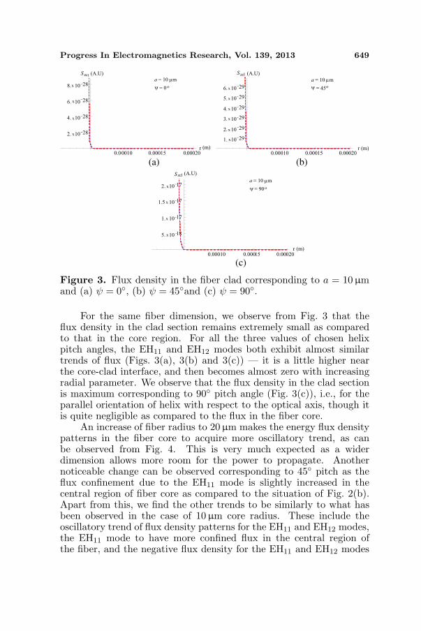
Figure 3. Flux density in the fiber clad corresponding to a = 10µmand (a) ψ = 0, (b) ψ = 45and (c) ψ = 90.
For the same fiber dimension, we observe from Fig. 3 that theflux density in the clad section remains extremely small as comparedto that in the core region. For all the three values of chosen helixpitch angles, the EH11 and EH12 modes both exhibit almost similartrends of flux (Figs. 3(a), 3(b) and 3(c)) — it is a little higher nearthe core-clad interface, and then becomes almost zero with increasingradial parameter. We observe that the flux density in the clad sectionis maximum corresponding to 90 pitch angle (Fig. 3(c)), i.e., for theparallel orientation of helix with respect to the optical axis, though itis quite negligible as compared to the flux in the fiber core.
An increase of fiber radius to 20µm makes the energy flux densitypatterns in the fiber core to acquire more oscillatory trend, as canbe observed from Fig. 4. This is very much expected as a widerdimension allows more room for the power to propagate. Anothernoticeable change can be observed corresponding to 45 pitch as theflux confinement due to the EH11 mode is slightly increased in thecentral region of fiber core as compared to the situation of Fig. 2(b).Apart from this, we find the other trends to be similarly to what hasbeen observed in the case of 10µm core radius. These include theoscillatory trend of flux density patterns for the EH11 and EH12 modes,the EH11 mode to have more confined flux in the central region ofthe fiber, and the negative flux density for the EH11 and EH12 modes

650 Baqir and Choudhury
5. 10 6 0.00001 0.000015 0.00002r
0.00001
0.00002
0.00003
0.00004
0.00005
0.00006
Szc
5. 10 6 0.00001 0.000015 0.00002r
0.00001
0.00002
0.00003
0.00004
0.00005
0.00006
Szc
5. 10 6 0.00001 0.000015 0.00002r
1.0
0.8
0.6
0.4
0.2
Szc
a= 20 m
= 0
a= 20 m
= 45
a = 20 m
= 90
µ
ψ ο
µ
ψ ο
µ
ψ ο
(a) (b)
(c)
−x
−x −x
(A.U)
(m)
(A.U)
(m)
(A.U)
(m)
Figure 4. Flux density in the fiber core corresponding to a = 20µmand (a) ψ = 0, (b) ψ = 45and (c) ψ = 90.
0.00010 0.00015 0.00020r
2. 10 17
4. 10 17
6. 10 17
8. 10 17
1. 10 16
Szcl
0.00010 0.00015 0.00020r
2. 10 32
4. 10 32
6. 10 32
8. 10 32
1. 10 31
Szcl
0.00010 0.00015 0.00020r
5. 10 32
1. 10 31
1.5 10 31
S zcla = 20 m
= 0
a = 20 m
= 45
a = 20 m
= 90
µ
ψ ο
(a) (b)
(c)
µ
ψ ο
µ
ψ ο−
−
−
x
x
x
−
−
−
−
−
x
x
x
x
x
−
−
−
−
−
x
x
x
x
x
(A.U)
(m)
(A.U)
(m)
(A.U)
(m)
Figure 5. Flux density in the fiber clad corresponding to a = 20µmand (a) ψ = 0, (b) ψ = 45and (c) ψ = 90.

Progress In Electromagnetics Research, Vol. 139, 2013 651
0.00001 0.00002 0.00003 0.00004 0.00005r
1.0
0.8
0.6
0.4
0.2
Szc
0.00001 0.00002 0.00003 0.00004 0.00005r
0.00001
0.00002
0.00003
0.00004
0.00005
Szc
0.00001 0.00002 0.00003 0.00004 0.00005r
0.00002
0.00004
0.00006
0.00008
Szca = 50 m
= 0
a = 50 m
= 45
a = 50 m
= 90
(a) (b)
(c)
µ
ψ ο
µ
ψ ο
µ
ψ ο
(A.U)
(m)
(A.U)
(m)
(A.U)(m)
Figure 6. Flux density in the fiber core corresponding to a = 50µmand (a) ψ = 0, (b) ψ = 45 and (c) ψ = 90.
0.00008 0.00010 0.00012 0.00014 0.00016 0.00018 0.00020r
1. 10 15
2. 10 15
3. 10 15
4. 10 15
5. 10 15
6. 10 15
Szcl
0.00008 0.00010 0.00012 0.00014 0.00016 0.00018 0.00020r
5. 10 30
1. 10 29
1.5 10 29
2. 10 29
2.5 10 29
Szcl
0.00008 0.00010 0.00012 0.00014 0.00016 0.00018 0.00020r
1. 10 40
2. 10 40
3. 10 40
4. 10 40
5. 10 40
Szcla = 50 m
= 0
a = 50 m
= 45
a = 50 m
= 90
(a) (b)
(c)
ψ ο
µ
ψ ο
µ
ψ ο
µ−
−
−
−
−
−
−
−
−
−
−
−
−
−
−
−
x
x
x
x
x
x
x
x
x
x
x
x
x
x
x
x
(A.U)
(m)
(A.U)
(m)
(A.U)
(m)
Figure 7. Flux density in the fiber clad corresponding to a = 50µmand (a) ψ = 0, (b) ψ = 45 and (c) ψ = 90.
corresponding to the case of 90 helix pitch. Fig. 5 indicates the similar(to the case of Fig. 3) trends of flux density in the fiber clad too exceptthe fact that it is further reduced in this case, as compared to what
652 Baqir and Choudhury
has been observed in Fig. 3. Otherwise, for all the three values ofpitch angles, both the EH11 and EH12 modes show exactly similartrend as noticed before — it does have negligibly small values in theneighborhood of core-clad interface, and vanishes with the increase inradial parameter.
A further increase of radial dimension to 50µm brings in primechanges in flux density patterns in respect of the more oscillatorybehavior of those, as can be observed in Fig. 6. We notice that fluxdue to both the EH11 and EH12 modes exhibit more dense oscillations,which is essentially owing to the allowance of the sustained modesto have more rooms while propagating; flux decreases with increasingradial direction, and the case of 90 helix pitch angle exhibits negativeflux. In the clad section, the flux density is further reduced near thecore-clad boundary (Fig. 7) as compared to the situations in Figs. 3and 5. Apart from this, the other trends are almost similar to whatobserved in respect of lower fiber dimensions.
4. CONCLUSION
From the foregoing discussions, inference can be drawn that theloading of conducting sheath helix at the core-clad interface bringsin alterations in the dispersion properties of fiber. Studies have beenmade considering a few values of helix pitch angles as well as fiberdimensions. It has been found that the propagation of flux densityis greatly governed by the introduced helix pitch. As such, thepropagation features of these guides can be tailored on demand, whichwould find potential optical applications.
ACKNOWLEDGMENT
This work is partially supported by the Fundamental Research GrantProject (FRGS/1/2011/TK/UKM/01/16) by the Ministry of HigherEducation (Malaysia); the authors are thankful to the Ministry. Theauthors are thankful to the anonymous reviewer for constructivecriticisms on the text of the manuscript, which essentially helped toimprove its status.
REFERENCES
1. Choudhury, P. K. and O. N. Singh, “Some multilayered andother unconventional lightguides,” Electromagnetic Fields inUnconventional Structures and Materials, O. N. Singh andA. Lakhtakia, Eds., 289–357, Wiley, USA, 2000.

Progress In Electromagnetics Research, Vol. 139, 2013 653
2. Choudhury, P. K. and T. Yoshino, “Characterization of opticalpower confinement in a simple chirofiber,” Optik, Vol. 13, 89–95,2002.
3. Choudhury, P. K. and T. Yoshino, “A rigorous analysis of thepower distribution in plastic clad annular core optical fibers,”Optik, Vol. 113, 481–488, 2002.
4. Cheng, S. F. and L. K. Chau, “Colloidal gold-modified opticalfiber for chemical and biochemical sensing,” Anal. Chem., Vol. 75,16–21, 2003.
5. Nair, A. and P. K. Choudhury, “On the analysis of field patterns inchirofibers,” Journal of Electromagnetic Waves and Applications,Vol. 21, No. 15, 2277–2286, 2007.
6. Choudhury, P. K. and D. Kumar, “Towards dispersion relationsfor tapered core dielectric elliptical fibers,” Optik, Vol. 118, 340–344, 2007.
7. Yeh, C. and I. F. Shimabukuro, The Essence of DielectricWaveguides, Springer, New York, 2008.
8. Choudhury, P. K. and W. K. Soon, “TE mode propagationthrough tapered core liquid crystal optical fibers,” Progress InElectromagnetics Research, Vol. 104, 449–463, 2010.
9. Amin, A. S. N., M. Mirhosseini, and M. Shahabadi, “Modal anal-ysis of multilayer conical dielectric waveguides for azimuthal in-variant modes,” Progress In Electromagnetics Research, Vol. 105,213–229, 2010.
10. Duan, Z., Y. Wang, X. Mao, W.-X. Wang, and M. Chen, “Exper-imental demonstration of double-negative metamaterials partiallyfilled in a circular waveguide,” Progress In Electromagnetics Re-search, Vol. 121, 215–224, 2011.
11. Kesari, V. and J. P. Keshari, “Analysis of a circularwaveguide loaded with dielectric and metal discs,” Progress InElectromagnetics Research, Vol. 111, 253–269, 2011.
12. Choudhury, P. K., “Dispersion behavior of gold-nanocoateddielectric optical fibers,” Adv. in Mat. Sci. Eng., Vol. 2012, ArticleID 214614, 1–7, 2012.
13. Baqir, M. A. and P. K. Choudhury, “On the energy flux through auniaxial chiral metamaterial made circular waveguide under PMCboundary,” Journal of Electromagnetic Waves and Applications,Vol. 26, No. 16, 2165–2175, 2012.
14. Zarifi, D., A. Abdolali, M. Soleimani, and V. Nayyeri,“Inhomogeneous planar layered chiral media: Analysis of wavepropagation and scattering using Taylor’s series expansion,”

654 Baqir and Choudhury
Progress In Electromagnetics Research, Vol. 125, 119–135, 2012.15. Choudhury, P. K., “Evanescent field enhancement in liquid crystal
optical fibers — A field characteristics based analysis,” Adv. inCondensed Mat. Phys., Vol. 2013, Article ID 504868, 1–9, 2013.
16. Dong, J. and J. Li, “Characteristics of guided modes inuniaxial chiral circular waveguides,” Progress In ElectromagneticsResearch, Vol. 124, 331–345, 2012.
17. Baqir, M. A. and P. K. Choudhury, “Propagation through uniaxialanisotropic chiral waveguide under DB-boundary conditions,”Journal of Electromagnetic Waves and Applications, Vol. 27,No. 6, 783–793, 2013.
18. Singh, U. N., O. N. Singh II, P. Khastgir, and K. K. Dey,“Dispersion characteristics of a helically cladded step-index opticalfiber: An analytical study,” J. Opt. Soc. Am. B, Vol. 12, 1273–1278, 1995.
19. Kumar, D. and O. N. Singh, II, “Modal characteristic equationand dispersion curves for an elliptical step-index fiber with aconducting helical winding on the core cladding boundary: Ananalytical study,” J. Light. Tech., Vol. 20, 1416–1424, 2002.
20. Kumar, D., P. K. Choudhury, and F. A. Rahman, “Loweccentricity elliptical fibers with helical windings under slow-waveconsideration — Some special cases,” Optik, Vol. 121, 926–933,2010.
21. Pierce, J. R., Travelling Wave Tubes, D. Van Nostrand, NJ, 1950.22. Lim, K. Y., P. K. Choudhury, and Z. Yusoff, “Chirofibers with
helical windings — An analytical investigation,” Optik, Vol. 121,980–987, 2010.
23. Choudhury, P. K., “Transmission through twisted clad liquidcrystal optical fibers,” Progress In Electromagnetics Research,Vol. 131, 169–184, 2012.
24. Kumar, D., P. K. Choudhury, and O. N. Singh, II, “Towardsthe dispersion relations for dielectric optical fibers with helicalwindings under slow- and fast-wave considerations — Acomparative analysis,” Progress In Electromagnetics Research,Vol. 80, 409–420, 2008.
25. Abramowitz, A. and I. A. Stegun, Handbook of MathematicalFunctions, Dover, New York, 1970.
26. Adams, M. J., An Introduction to Optical Waveguides, 250–257,Wiley, UK, 1981.
27. Cherin, A. H., An Introduction to Optical Fibers, Chapt. 2,McGraw-Hill, New York, 1987.