efficient asymmetric secure iscsi - …cs.uccs.edu/~gsc/pub/master/msanduku/doc1/reportb1.doc ·...
TRANSCRIPT

EFFICIENT ASYMMETRIC SECURE ISCSI
BYMURTHY S. ANDUKURI
A thesis submitted to the Graduate faculty of the
University of Colorado at Colorado Springs
in partial fulfillment of the
requirements for the degree of
Master Of Science
Department of Computer Science
2006

© Copyright by Murthy S. Andukuri 2006
All Rights Reserved
ii

This thesis for the M.S. Of Computer Science degree by
Murthy S. Andukuri
has been Approved for the
Department of Computer Science by
__________________________________________________
C. Edward chow, Chair
__________________________________________________
Marijke Augusteijn
__________________________________________________
Jugal Kalita
_______________Date
iii

Murthy, Andukuri S. (M.S., Computer Science)
Efficient Asymmetric Secure iSCSI
Thesis directed by : Professor C. Edward Chow
iSCSI is an application level protocol that enables storage of data on a disk
attached to a networked remote host. IPsec, when used in conjunction with iSCSI, secures
this data while in transit. IPsec provides security by encrypting the data at the sender and
decrypting at the receiver. This means that the data is exposed and vulnerable at the
receiver. There are currently two choices to secure the data at rest on the remote disk -
both involving the use of third party encryption software to either (1) re-encrypt the data
at the remote end or, (2) Encrypt the data before transmitting to the remote end. The
second option, while better than the first, still requires additional encryption software on
the remote site, impacts on overall performance, and introduces additional security risk .
The current thesis proposes a new asymmetric IPsec scheme to enhance the security of
data at the remote end, while simultaneously avoiding the cost of additional of software
and improving the over all performance. The idea is to apply IPsec encryption/decryption
in a segmented manner on the iSCSI traffic, such that the user data remains encrypted
after leaving the sender, and is decrypted only when it is retrieved by the sender. A dual
key cryptographic scheme is proposed where the private key is used to encrypt the iSCSI
payload at the sender and traditional IPsec is modified to encrypt/decrypt only on the
TCP/iSCSI headers. A development test bed was built using User-Mode-Linux virtual
machines for developing/debugging the asymmetric IPsec software and running as the
iv

sender and receiver to verify the functionality and security features of the proposed
design. A benchmark test bed is being built with two real PCs where the asymmetric
IPsec modules can be dynamically loaded. The performance results are expected to show
that the proposed asymmetric IPsec scheme reduces the IPsec processing time by two
thirds.
v

CONTENTS
Chapter
1. Introduction...........................................................................................................................11
1.1 Motivation for enhancing remote storage security..........................................................11
2 IPsec......................................................................................................................................19
2.1 The SAD and SPD databases...........................................................................................20
2.2 How the SAD and SPD are used for outbound traffic.....................................................21
2.3 How the SAD and SPD are used for inbound traffic.......................................................22
2.4 IPsec deployment options................................................................................................23
2.4.1 Basic options of IPsec deployment.......................................................................23
2.4.1.1 IPsec AH in transport mode.............................................................................24
2.4.1.2 IPsec ESP in transport mode............................................................................26
2.4.1.3 IPsec AH in tunnel mode.................................................................................27
2.4.1.4 IPSec ESP in tunnel mode................................................................................29
2.5 IPsec Implementations.....................................................................................................30
2.6 IPsec operation modes.....................................................................................................30
2.6.1 'Daemon' mode of IPsec operation........................................................................30
2.6.2 Manual mode of IPsec operation...........................................................................30
3 Chapter 3...............................................................................................................................31
SCSI based Storage Options...........................................................................................................31
vi
3.1 SCSI based Internet storage architectures.......................................................................33
3.1.1 FCIP: Fiber channel over IP..................................................................................33
3.1.2 iFCP.......................................................................................................................34
3.1.3 iSCSI.....................................................................................................................34
3.1.4 ISCSI Command progression between Initiator and target...................................36
3.1.4.1 iSCSI Protocol layers.......................................................................................37
3.1.5 Motivation for the project.....................................................................................42
3.1.6 Stages in iSCSI initiator-target interactions..........................................................43
3.1.6.1 Naming/Addressing..........................................................................................43
3.1.6.1.1 Formats of iSCSI name..........................................................................43
3.1.6.2 Session establishment and management..........................................................44
3.1.7 Phases of iSCSI session of interest in the current thesis.......................................46
3.1.8 Full Feature Phase.................................................................................................49
3.2 iSCSI 'Write's..................................................................................................................49
3.3 iSCSI 'Read's...................................................................................................................50
3.4 Other PDU exchange relevant to the thesis.....................................................................51
4 Details of the proposed enhancement...................................................................................52
4.1 When the initiator is sending iSCSI date to the target.....................................................52
4.2 When the initiator is trying to read the iSCSI data from the target.................................52
4.3 The native IPsec operation on iSCSI...............................................................................53
4.4 How the native-IPsec issues are managed in the implementation...................................55
4.4.1 Identify iSCSI data................................................................................................55
vii
4.4.2 Encrypt the headers separately..............................................................................55
4.4.2.1 iSCSI packets which do not carry any user data..............................................56
4.4.2.2 iSCSI packets carrying user data......................................................................56
4.4.3 Updating TCP checksums:....................................................................................58
4.4.3.1 The sending side in the initiator:......................................................................58
4.4.3.2 The receiving side of the initiator....................................................................59
4.4.3.3 Scope of the implemented solution..................................................................60
4.4.3.4 Ethereal Packet pattern for write to target........................................................62
4.4.3.5 Ethereal Packet pattern for read from target....................................................63
5 Performance data and analysis..............................................................................................64
5.1 Role of User Mode Linux................................................................................................64
5.2 Performance Analysis......................................................................................................66
5.2.1 Computational details of the available scheme.....................................................67
5.3 Performance data of the proposed scheme on a UML test bed.......................................69
5.4 Analysis...........................................................................................................................75
6 Lessons Learnt......................................................................................................................76
7 Future Directions..................................................................................................................79
8 Conclusions...........................................................................................................................81
8.1 Advantages of the current approach................................................................................81
8.2 Limitations of the current approach.................................................................................82
9 Bibliography.........................................................................................................................83
10 APPENDIX A : User Guide of AIPsec................................................................................85
viii

10.1 Setting up IPsec..........................................................................................................85
10.1.1 Build the setkey utility..........................................................................................85
10.1.2 Package dependencies for setkey..........................................................................85
10.1.3 Commands to build setkey....................................................................................85
10.1.4 Generating a key....................................................................................................86
10.1.5 Generating SAD and SPD entries using the setkey utility on target.....................86
10.1.6 Displaying SAD entries on the target....................................................................87
10.1.7 Displaying SPD entries on the target....................................................................88
10.1.8 Generating SAD and SPD entries using the setkey utility on initiator.................89
10.1.9 Displaying the SAD entries on the initiator..........................................................89
10.1.9.1 Displaying SPD entries on the initiator......................................................90
10.2 Appendix B : Running the iSCSI target program.......................................................91
10.2.1 Installing target on a host machine........................................................................91
10.2.2 Installing target on a UML....................................................................................91
10.2.3 Running the target.................................................................................................92
10.3 Appendix C: Running iSCSI Initiator program..........................................................93
10.3.1 Installing the initiator in the host machine............................................................93
10.3.2 Installing the initiator in a virtual machine...........................................................93
10.3.3 Running the iscsi initiator.....................................................................................94
10.3.3.1 Sample iSCSI Initiator Config file..............................................................95
10.3.3.2 Sequence of commands to run iSCSI Initiator............................................96
10.4 Appendix D: Compiling UMLs, setting up bridge and debugging kernel modules
ix
with UML..................................................................................................................................97
10.4.1 Building and installing uml modules....................................................................97
10.4.2 Debugging uml modules........................................................................................97
10.4.2.1 Perl script to setup ground for debugging modules in gdb.........................97
10.4.2.2 Using GDB to debug modules....................................................................99
10.5 Appendix E : Compiling sg_dd and setting it up.....................................................102
11 Appendix F: A typical run through the test bed.................................................................103
11.1 Step 1: Create the ‘disk’ on the target.....................................................................103
11.2 Step 2: Start the iSCSI target software.....................................................................103
11.3 Step 3: Start the iSCSI Initiator daemon..................................................................103
11.4 Step 4 : Login to the target.......................................................................................104
11.5 Step 5 : Verifying that data is scrambled on the target............................................105
11.6 Step 6: Read data from the Initiator.........................................................................105
11.7 Step 7: Verifying the correctness of the data...........................................................106
x
TABLES
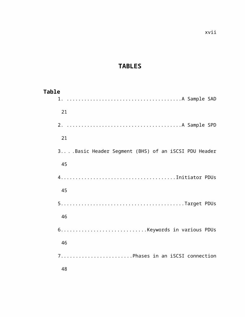
Table 1. A Sample SAD..........................................................................21
2. A Sample SPD..........................................................................21
3. Basic Header Segment (BHS) of an iSCSI PDU Header..........45
4. Initiator PDUs..........................................................................45
5. Target PDUs.............................................................................46
6. Keywords in various PDUs.......................................................46
7. Phases in an iSCSI connection................................................48
8. PDU exchange during an initiator 'write'................................50
9. PDU exchange during a an initiator 'read'..............................51
10. Number of 16-byte blocks encrypted during round-trip of 1
TCP segment........................................................................................69
11. Performance of the UML test bed when transferring a 1K file
70
12. Performance of the UML test bed when transferring a 10K file
70
13. Performance of the UML test bed when transferring a 100K
file 71
xi
14. Performance of the UML test bed when transferring a 1M file
71
15. Performance of the UML test bed when transferring a 10M file
72
16. Performance of the UML test bed when transferring a 100M
file 72
xii
FIGURES
Figure
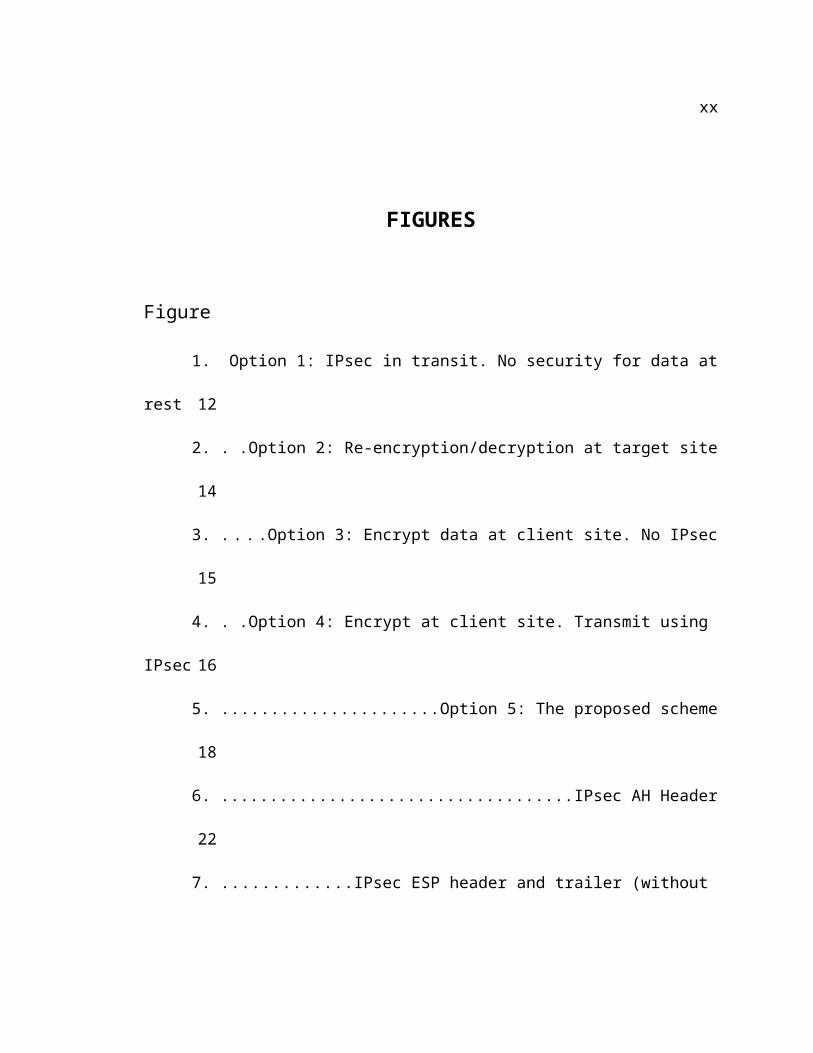
1. Option 1: IPsec in transit. No security for data at rest.............12
2. Option 2: Re-encryption/decryption at target site....................14
3. Option 3: Encrypt data at client site. No IPsec.........................15
4. Option 4: Encrypt at client site. Transmit using IPsec.............16
5. Option 5: The proposed scheme...............................................18
6. IPsec AH Header.......................................................................22
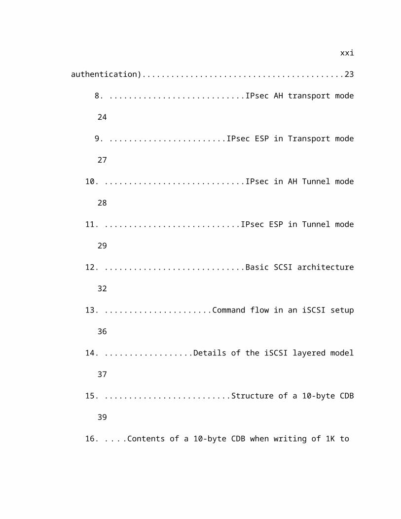
7. IPsec ESP header and trailer (without authentication)............23
8. IPsec AH transport mode..........................................................24
9. IPsec ESP in Transport mode...................................................27
10. IPsec in AH Tunnel mode..........................................................28
11. IPsec ESP in Tunnel mode........................................................29
12. Basic SCSI architecture............................................................32
13. Command flow in an iSCSI setup..............................................36
14. Details of the iSCSI layered model...........................................37
15. Structure of a 10-byte CDB.......................................................39
16. Contents of a 10-byte CDB when writing of 1K to target.........40
xiii
17. Contents of a 10-byte CDB when reading 1K from target........41
18, PDU exchange during an iSCSI login.......................................48
19. Packet modification under proposed scheme...........................57
20. Packet sequence between initiator and target during a 'write'62
21. Packet sequence between initiator and target during a 'read'.63
22. A schematic of the UML test bed used in the current thesis. . .66
24. Performance under currently available alternative..................73
25. Performance under the proposed scheme................................74
26. Performance of the different schemes of iSCSI communication
75
xiv
Chapter 1
1. Introduction
The goals of the current thesis are as follows.
To propose a dual-key asymmetric cryptographic enhancement of IPsec that reduces
IPsec processing time and enhances data security during remote storage using iSCSI.
To demonstrate how virtual machines running UML can be used to develop/modify/run
kernel and networking software on virtual test beds for networking projects.
1.1 Motivation for enhancing remote storage security
Remote backup of data for security has become a subject of rapidly growing interest in the recent
times [1][2]. The importance of backups, and remote storage for security in today's networked
world can hardly be overstated. Of the various options available, iSCSI seemed the most worthy
of study because its design smartly makes full use of the universally proven strengths of existing
protocols like TCP, IP and IPsec, thereby reducing the cost, effort and time of learning, setup and
deployment.
The various mechanisms that can be used are FCIP, iFCP, iSCSI [3][4]. Among these, iSCSI has
been getting a lot of attention of late because it can be run on commonly available, relatively
inexpensive IP networking infrastructure already in place.
iSCSI is an application layer protocol that uses the available IP network to make a remote storage
disk accessible as a simulated local SCSI disk. This locally accessible remote disk can be written
to, or read from, like any local disk. An iSCSI setup has two parts - The iSCSI initiator is the
'client' program located on the source machine and writes to / read from the remote machine. The
iSCSI target is the software on the destination machine that helps store the data and return it on
demand. iSCSI restricts itself to handling the user-level data and leaves the actual details of
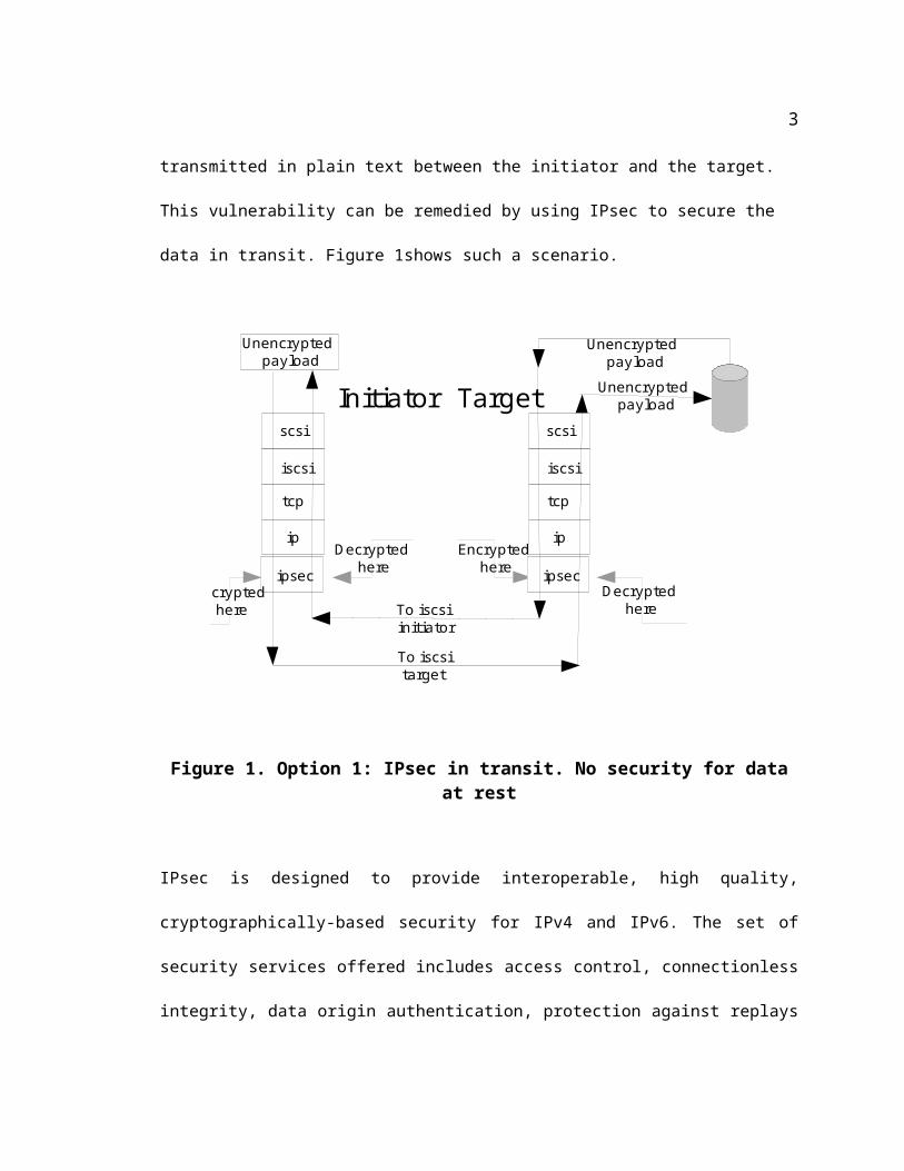
transmission to the TCP and IP layers. By default, the data is transmitted in plain text between the
initiator and the target. This vulnerability can be remedied by using IPsec to secure the data in
transit. Figure 1shows such a scenario.
scsi
iscsi
tcp
ip
ipsec
Unencrypted payload
Decrypted here
Encrypted here
Decrypted here
To iscsi target
To iscsi initiator
Encrypted here
Initiator Target Unencrypted payload
Unencrypted payload
scsi
iscsi
tcp
ip
ipsec
Figure 1. Option 1: IPsec in transit. No security for data at rest
2
IPsec is designed to provide interoperable, high quality, cryptographically-based security for IPv4
and IPv6. The set of security services offered includes access control, connectionless integrity,
data origin authentication, protection against replays (a form of partial sequence integrity),
confidentiality (encryption), and limited traffic flow confidentiality. These services are provided
at the IP layer, offering protection for IP and/or upper layer protocols [5].
IPsec encrypts the data leaving the network layer on the sender and, at the receiving end, decrypts
the data before it leaves the network layer. This secures the data in transit but does not help
secure the data AFTER it has reached its destination. This makes data very vulnerable to theft
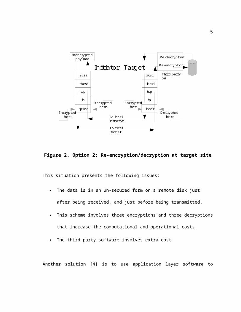
when the target site gets break-in [6].
This vulnerability can be alleviated by reencrypting the received data using a third party software
– and redecrypt, so that the IPsec layer can encrypt it in preparation for transmission back to the
sender. Figure 2 shows such a scenario.
3

Third party SW
scsi
iscsi
tcp
ip
ipsec
Re-decryption
Decrypted here
Encrypted here
Decrypted here
To iscsi target
To iscsi initiator
Encrypted here
Initiator Target Re-encryption
Unencrypted payload
scsi
iscsi
tcp
ip
ipsec
Figure 2. Option 2: Re-encryption/decryption at target site
This situation presents the following issues:
The data is in an un-secured form on a remote disk just after being received, and just
before being transmitted.
This scheme involves three encryptions and three decryptions that increase the
computational and operational costs.
The third party software involves extra cost
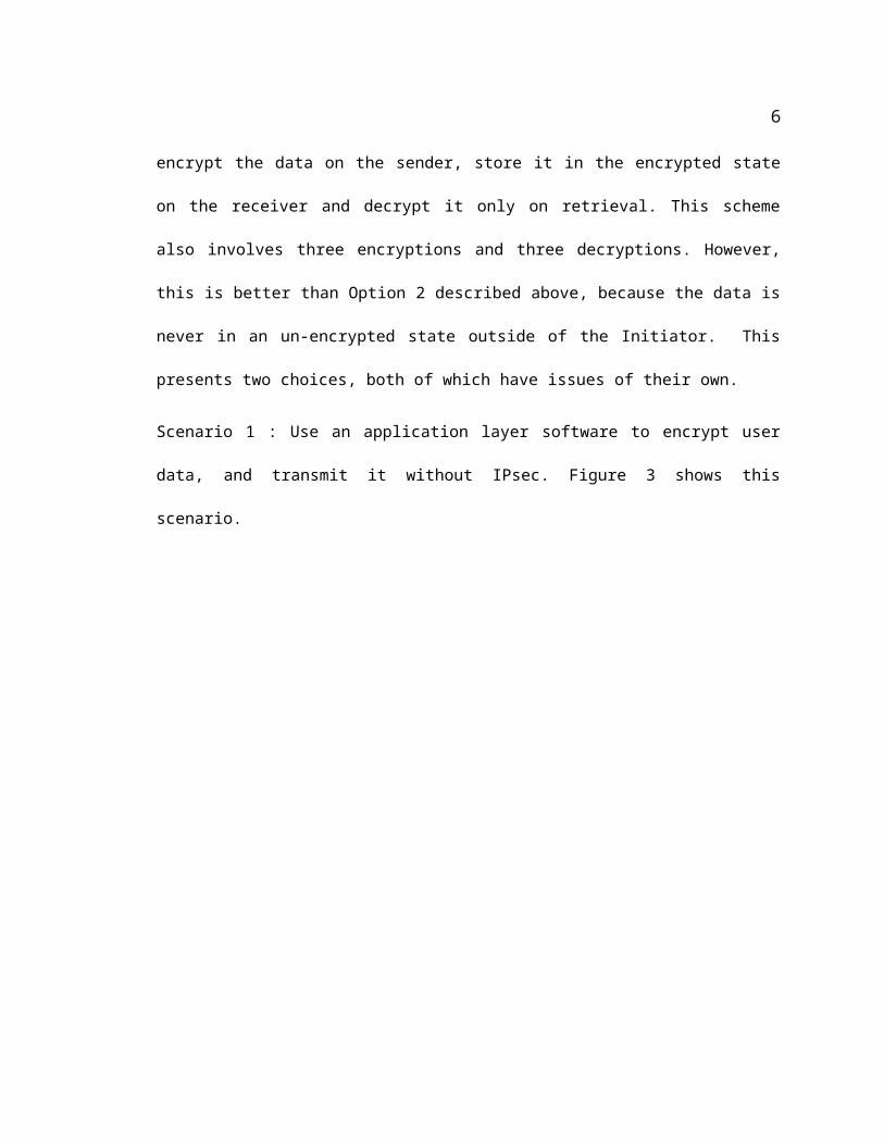
Another solution [4] is to use application layer software to encrypt the data on the sender, store it
in the encrypted state on the receiver and decrypt it only on retrieval. This scheme also involves
three encryptions and three decryptions. However, this is better than Option 2 described above,
4

because the data is never in an un-encrypted state outside of the Initiator. This presents two
choices, both of which have issues of their own.
Scenario 1 : Use an application layer software to encrypt user data, and transmit it without IPsec.
Figure 3 shows this scenario.
Payload withOriginal encryption
To iscsi target
Initiator TargetPayload with
original encryption
Unencrypted payload
OriginalEncryption at app layer
Payload RE-Decrypted at app layer
scsi
iscsi
tcp
ip
scsi
iscsi
tcp
ip
To iscsi initiator
Figure 3. Option 3: Encrypt data at client site. No IPsec
This leaves the iSCSI, TCP and IP headers exposed during transit. While the data is encrypted,
the headers remain vulnerable.
5
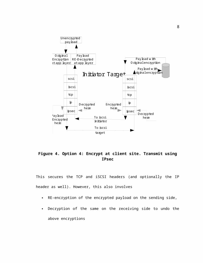
Scenario 2: Use an application layer software to encrypt user data and decrypt it after retrieval.
Transmit using IPsec. Figure 4 shows such a scenario.
Payload withOriginal encryption
Decrypted here
Encrypted here
Decrypted here
To iscsi target
To iscsi initiator
PayloadRE-Encrypted
here
Initiator TargetPayload with
original encryption
Unencrypted payload
OriginalEncryption at app layer
Payload RE-Decrypted at app layer
scsi
iscsi
tcp
ip
ipsec
scsi
iscsi
tcp
ip
ipsec
Figure 4. Option 4: Encrypt at client site. Transmit using IPsec
This secures the TCP and iSCSI headers (and optionally the IP header as well). However, this
also involves
RE-encryption of the encrypted payload on the sending side,
Decryption of the same on the receiving side to undo the above encryptions
RE-encryption of the encrypted payload on the receiving side for retrieval by sender
6
Decryption of the same on the sender (after retrieval) to undo the above, second
encryption.
As such, it is obvious that this scheme only partially addresses the shortcomings of the previous
approach.
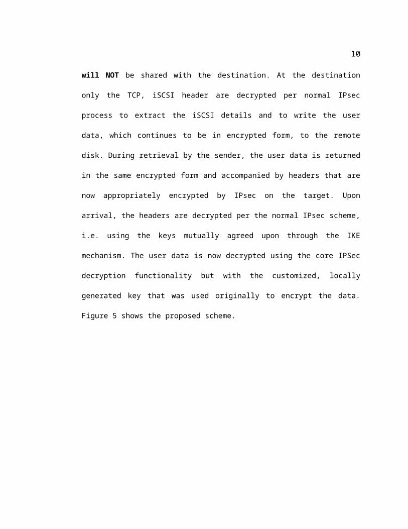
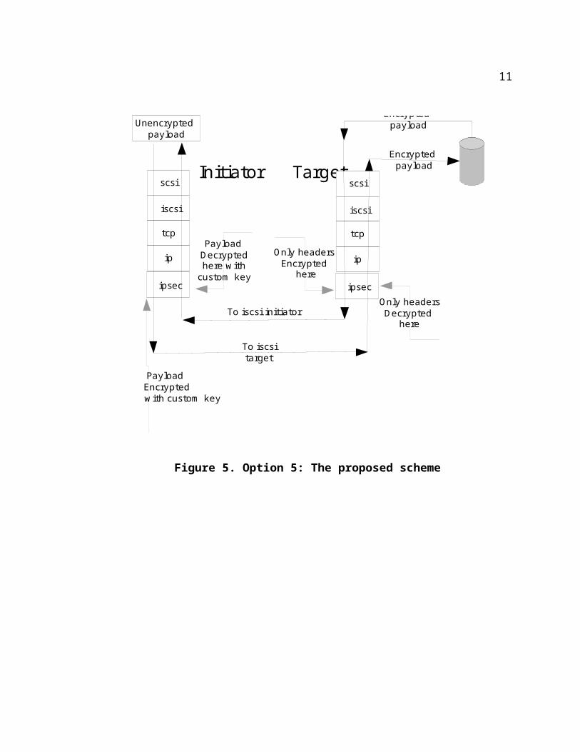
The proposed efficient asymmetric IPsec scheme hopes to address the above concerns as follows.
It is proposed that the process of encrypting/decrypting the transmitted data be divided into two
parts –
The encryption of the TCP and iSCSI headers is performed per the normal IPsec procedures –
using the keys generated and managed by Internet Key exchange (IKE) between the source
and destination.
The core IPsec encryption functionality, i.e., the algorithm implementation excluding the IKE,
is still used to encrypt the user data. However, the key for the encryption is generated on the
source machine independent of the IKE mechanism. This key will NOT be shared with the
destination. At the destination only the TCP, iSCSI header are decrypted per normal IPsec
process to extract the iSCSI details and to write the user data, which continues to be in
encrypted form, to the remote disk. During retrieval by the sender, the user data is returned in
the same encrypted form and accompanied by headers that are now appropriately encrypted by
IPsec on the target. Upon arrival, the headers are decrypted per the normal IPsec scheme, i.e.
using the keys mutually agreed upon through the IKE mechanism. The user data is now
decrypted using the core IPSec decryption functionality but with the customized, locally
generated key that was used originally to encrypt the data. Figure 5 shows the proposed
scheme.
7
Encrypted payload
Only headersDecrypted
here
Only headersEncrypted
here
Payload Decrypted here with custom key
To iscsi target
To iscsi initiator
Payload Encrypted
with custom key
Initiator TargetEncrypted
payload
Unencrypted payload
scsi
iscsi
tcp
ip
ipsec
scsi
iscsi
tcp
ip
ipsec
Figure 5. Option 5: The proposed scheme
8

Chapter 2
2 IPsec
IPsec [5][6] is the name given to a collection of protocols that together form the mandatory
security component of the next generation IPV6 protocol. This is an optional part of IPV4. IPSec
offers protection to the data by encrypting and/or authenticating it at the sender before
transmitting. There are three protocols in IPsec.
Internet Key Exchange (IKE) guides how a handshake is established between the sender
and receiver, how keys are exchanged and renewed. It has an IANA (Internet Assigned
Numbers authority) port number of 500.
ESP (Encapsulation Security Payload) guides how data can be encrypted at the sender
and decrypted at the receiver. This has an IANA protocol number of 50.
AH (Authentication Header) guides how the data can be authenticated at the sender and
verified at the receiver. The IANA protocol number for this protocol is 51.
There is a vast amount of literature available – explaining, analyzing and evaluating IPsec
protocols and implementation. A summary is given below to help understand the role and
9
relevance of IPsec in the current thesis. The figures are reproduced from [7] because they do an
excellent job of illustrating the concepts.
IPsec secures data traffic between two hosts by encrypting and/or authenticating the data. In
either case, the two hosts agree on details like the crypto algorithms, the keys, the lifetimes of the
keys etc during an IKE phase that takes place before the actual encryption/authentication. The
two hosts in question can be either gateways behind each of which there are other hosts as in any
subnet, or the actual points of termination for the traffic. In the former case, when hosts in one
subnet try to communicate with hosts in the other, the traffic can be protected by encrypting
/authenticating only in the span of the network between the gateways (not end-to-end). In this
case, the entire packet is embedded in new IP headers, thereby creating an IP tunnel. In the latter
case, IPsec is said to operate in the 'transport' mode. In either case, during the actual data transfer,
encryption and authentication headers and/or trailers are inserted into the data packets. The
placement of the headers/trailers depends on the actual mode of IPsec protection. These headers
carry information that helps the receiver look into its own IPsec-related databases (to be
discussed below) for identifying the information to decrypt/re-authenticate the data.
2.1 The SAD and SPD databases
Imagine data communication between hosts 'A' and ''B' using IPsec. The set of all parameters like
the protocol to use (AH or ESP), keys, crypto algorithms, lifetime keys, etc., that either of the
hosts needs to process the payload. is called a 'Security Association' (SA). This is unidirectional
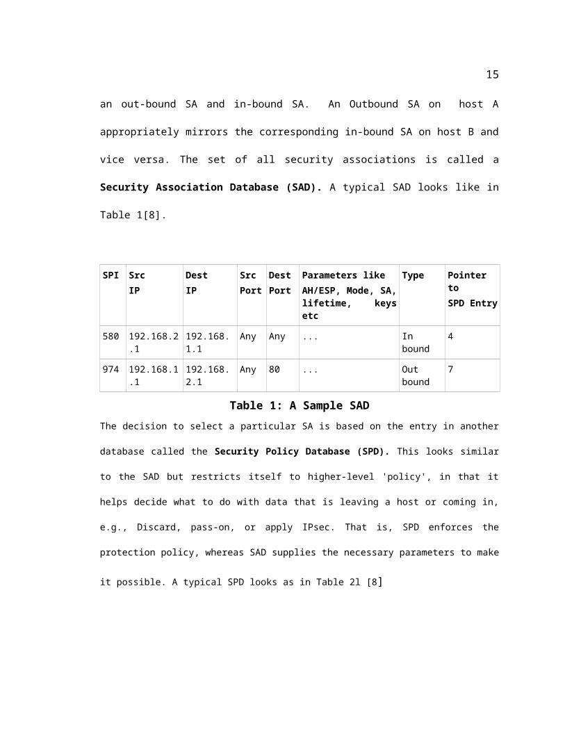
therefore each host has an out-bound SA and in-bound SA. An Outbound SA on host A
appropriately mirrors the corresponding in-bound SA on host B and vice versa. The set of all
security associations is called a Security Association Database (SAD). A typical SAD looks like
10
in Table 1[8].
SPI Src IP
Dest IP
Src Port
Dest Port
Parameters likeAH/ESP, Mode, SA, lifetime, keys etc
Type Pointer to SPD Entry
580 192.168.2.1 192.168.1.1 Any Any ... In bound 4
974 192.168.1.1 192.168.2.1 Any 80 ... Out bound 7
Table 1: A Sample SADThe decision to select a particular SA is based on the entry in another database called the Security Policy
Database (SPD). This looks similar to the SAD but restricts itself to higher-level 'policy', in that it helps
decide what to do with data that is leaving a host or coming in, e.g., Discard, pass-on, or apply IPsec. That
is, SPD enforces the protection policy, whereas SAD supplies the necessary parameters to make it possible.
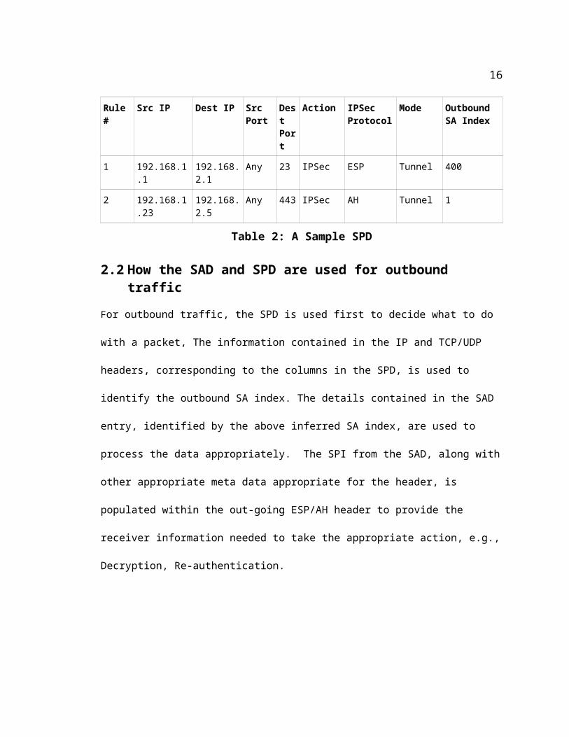
A typical SPD looks as in Table 2l [8]
Rule # Src IP Dest IP Src Port
Dest Port
Action IPSec Protocol
Mode Outbound SA Index
1 192.168.1.1 192.168.2.1 Any 23 IPSec ESP Tunnel 400
2 192.168.1.23 192.168.2.5 Any 443 IPSec AH Tunnel 1
Table 2: A Sample SPD
2.2 How the SAD and SPD are used for outbound traffic
For outbound traffic, the SPD is used first to decide what to do with a packet, The information
contained in the IP and TCP/UDP headers, corresponding to the columns in the SPD, is used to
identify the outbound SA index. The details contained in the SAD entry, identified by the above
inferred SA index, are used to process the data appropriately. The SPI from the SAD, along with
other appropriate meta data appropriate for the header, is populated within the out-going ESP/AH
header to provide the receiver information needed to take the appropriate action, e.g., Decryption,
11
Re-authentication.
2.3 How the SAD and SPD are used for inbound traffic
The processing on the in-bound side is the converse of the above out-bound case. The SPI, the
destination IP, and the security protocol information contained in the incoming packet header
(AH or ESP) are used to identify the entry in the SAD. Only after an SA is found and the identity
of the sender established, does IPsec proceed to SPD to decide what to do with the packet.
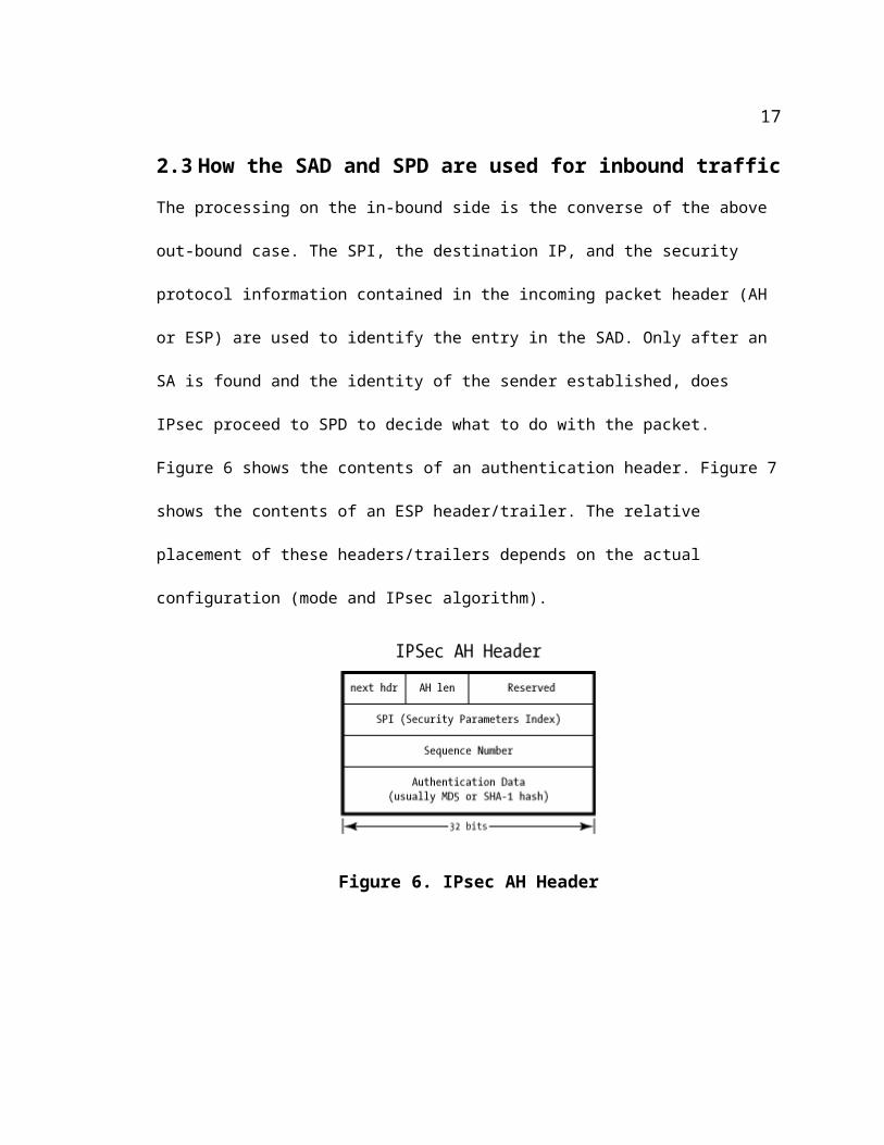
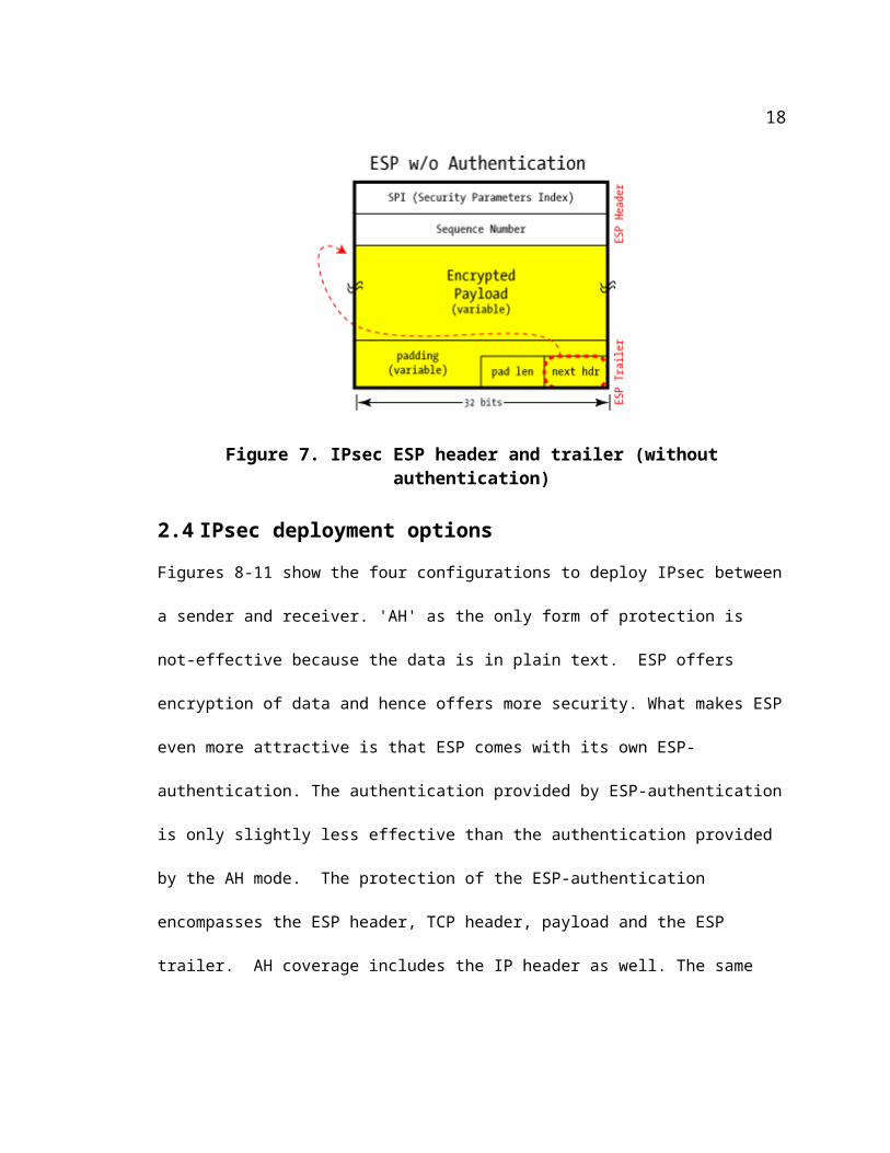
Figure 6 shows the contents of an authentication header. Figure 7 shows the contents of an ESP
header/trailer. The relative placement of these headers/trailers depends on the actual configuration
(mode and IPsec algorithm).
Figure 6. IPsec AH Header
12

Figure 7. IPsec ESP header and trailer (without authentication)
2.4 IPsec deployment options
Figures 8-11 show the four configurations to deploy IPsec between a sender and receiver. 'AH' as
the only form of protection is not-effective because the data is in plain text. ESP offers
encryption of data and hence offers more security. What makes ESP even more attractive is that
ESP comes with its own ESP-authentication. The authentication provided by ESP-authentication
is only slightly less effective than the authentication provided by the AH mode. The protection of
the ESP-authentication encompasses the ESP header, TCP header, payload and the ESP trailer.
AH coverage includes the IP header as well. The same algorithms are used for authentication in
both ESP-authentication and AH. Given this scenario, there is a debate in the security community
if AH needs to be offered as an option at all [9]. AH may be deprecated in the future.
2.4.1 Basic options of IPsec deployment
In the following sections, the cases of AH in transport and tunnel mode are included for
illustration and completeness. The current thesis is all about making user-data most secure by
keeping it in an encrypted state as much as possible. As such, the AH mode is not directly
13
relevant to this thesis.
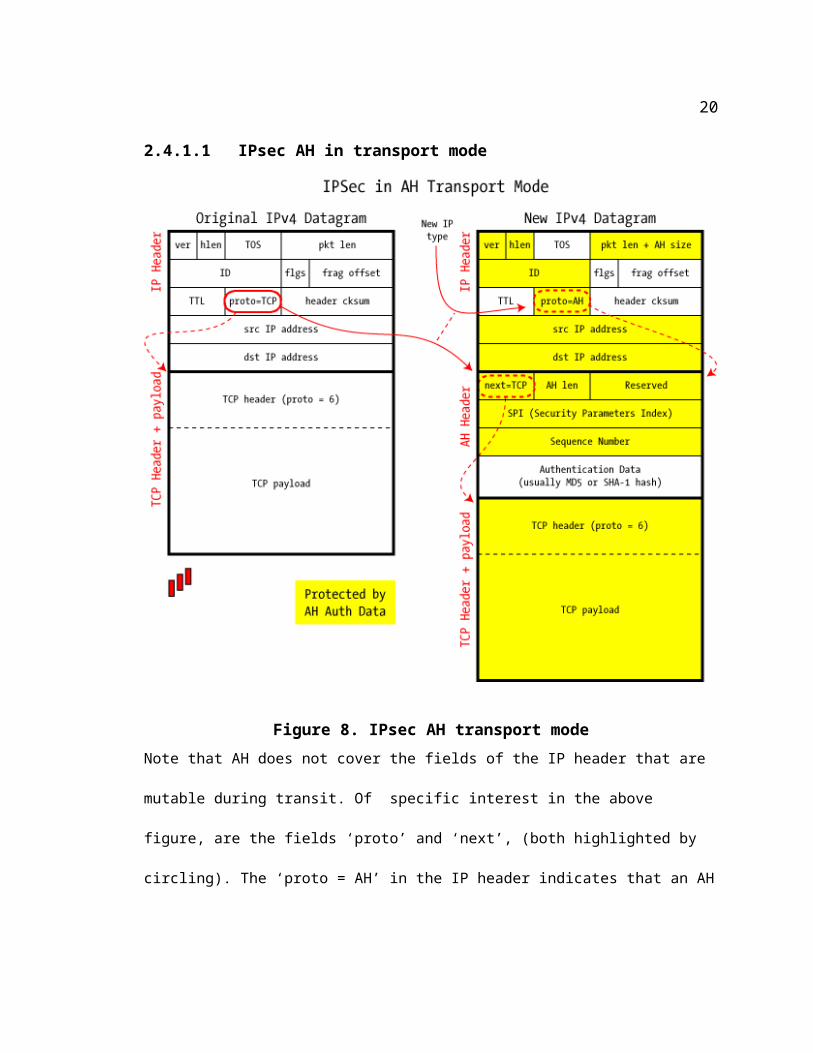
2.4.1.1 IPsec AH in transport mode
Figure 8. IPsec AH transport modeNote that AH does not cover the fields of the IP header that are mutable during transit. Of
specific interest in the above figure, are the fields ‘proto’ and ‘next’, (both highlighted by
circling). The ‘proto = AH’ in the IP header indicates that an AH header follows. ‘next=TCP’ in
the AH header indicates that the TCP header follows.
14
2.4.1.2 IPsec ESP in transport mode
Of specific interest in Figure 9 is the fact that the ‘next’ field is a part of the ESP trailer , and not
the ESP header. This is meant to provide extra security because; the ESP trailer is also encrypted.
Also, of interest is the part of the packet marked as ‘Authenticated Data’. This shows the part
covered by ESP authentication.
15
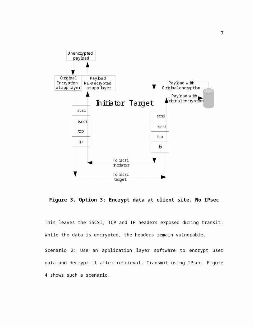
Figure 9. IPsec ESP in Transport modeThe transport mode is meant for providing host-to-host security to the data. iSCSI's initiator-
target setup requires host-to-host security and hence ESP with authentication in transport mode
was chosen for the current thesis.
16
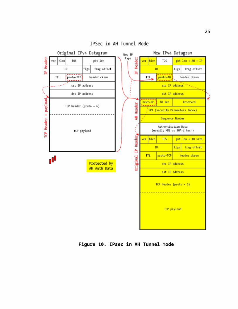
2.4.1.3 IPsec AH in tunnel mode
Figure 10 shows a packet protected by AH in tunnel mode. Note that the ‘next’ field in the AH
header indicates that the header following is an IP header. This refers to the original IP header.
17
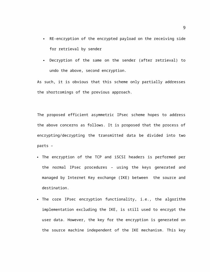
Figure 10. IPsec in AH Tunnel mode
18
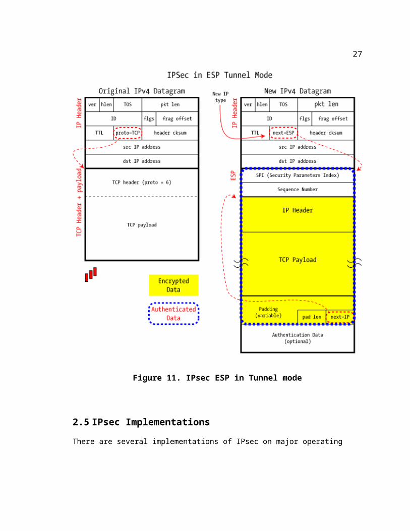
2.4.1.4 IPSec ESP in tunnel mode
Figure 11 shows a packet protected by ESP in tunnel mode. The portion highlighted as
‘Encrypted Data’ demonstrates that the original packet is encrypted in its entirety.
Figure 11. IPsec ESP in Tunnel mode
19
2.5 IPsec Implementations
There are several implementations of IPsec on major operating systems. Notable among them is
the KAME project [10] that is the source of the IPsec implementation on NetBSD and FreeBSD.
KAME also had an implementation for Linux even though it did not make it into the 2.6 stack.
Linux has three major implementations – an implementation that is native to the linux 2.6 stack,
and two others – 'Openswan' [11]and 'StrongSwan'[12] that are derived from 'FreeSwan'[13] that
has been stopped in 2004. 'StrongSwan' and 'OpenSwan' are not a part of the native IPsec stack.
The current project uses the native IPsec stack for the following reasons
Native stack, by definition, is available everywhere.
The very idea of this project is to minimize the need for third-party software.
2.6 IPsec operation modes
2.6.1 'Daemon' mode of IPsec operation
The 'raccoon' utility provided by IPsec-tools [14] can be used to dynamically process key
exchange and enforce lifetime restrictions. The IPsec-tools package is a port of KAME's IPsec
tools for Linux 2.6. It supports NetBSD, FreeBSD as well.
2.6.2 Manual mode of IPsec operation
The package IPsec-tools provides the 'setkey' utility to manually setup security associations.
When IPsec is setup in manual mode between the sender and receiver, there is no automatic
regeneration of keys. Since the focus of the current thesis is a proof-of-concept, it was felt that the
manual mode should suffice.
The current project uses the setkey utility. The instructions to build the utility, the details of the
20
SAD and SPD, the configuration files used are all available in Appendix B.
21
Chapter 3
3 SCSI based Storage Options
SCSI (Small Computer Serial Interface) is a device independent I/O sub-system interface that
began to be developed during the early 1980s. The driving force behind its development was the
need to eliminate physical addressing of data blocks in terms of cylinder, head, sector (CHS), and
develop a way of logical addressing of the blocks. This frees the host from having to know the
exact physical organization of a drive [15]. A brief summary of the SCSI architecture is given
below to highlight attributes that are relevant to understand the overall picture of the current
project. In its simplest form, the SCSI configuration can be shown as in Figure 12[15].
22
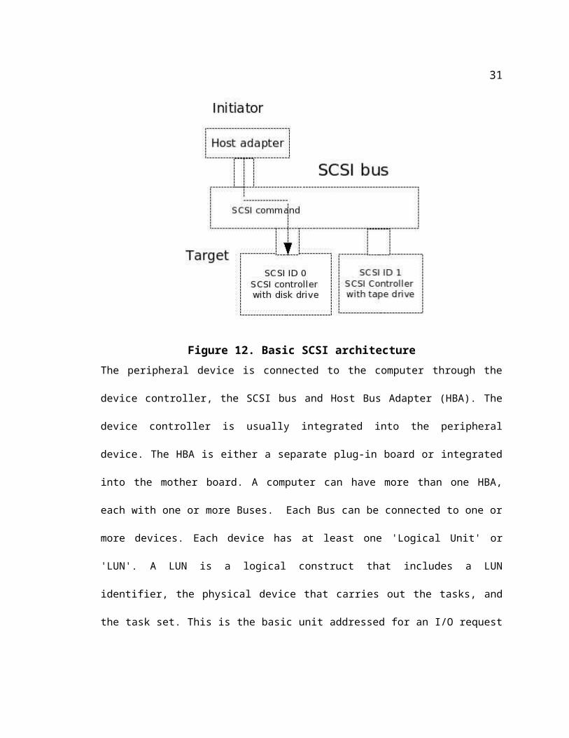
Figure 12. Basic SCSI architectureThe peripheral device is connected to the computer through the device controller, the SCSI bus
and Host Bus Adapter (HBA). The device controller is usually integrated into the peripheral
device. The HBA is either a separate plug-in board or integrated into the mother board. A
computer can have more than one HBA, each with one or more Buses. Each Bus can be
connected to one or more devices. Each device has at least one 'Logical Unit' or 'LUN'. A LUN is
a logical construct that includes a LUN identifier, the physical device that carries out the tasks,
and the task set. This is the basic unit addressed for an I/O request in the SCSI architecture.
Sophisticated tape and Optical devices have more than one LUN, because they support multiple
media. A disk normally constitutes a LUN, but a RAID array can be configured as one too.
Functionally, SCSI follows a client-server model in its architecture. The client ('initiator') makes
an I/O request. This request, as mentioned earlier, is addressed to a LUN of a target. This triggers
a task on the service delivery mechanism which is the SCSI bus. The server ('target') carries out
23
the task and sends the results back via the delivery mechanism. A Host Bus Adapter is an
example of an initiator. A disk drive is an example of a target. The width of a SCSI bus (and
hence the limit on the number of peripherals that can attach to it) has gone up from 8 bits for
SCSI-1 standard, to 32 bits in SCSI 3. The commands are packaged in a 'Command Descriptor
Block’ (CDB). The length of the CDB can be between 6 to 16 bytes. [16]
3.1 SCSI based Internet storage architectures
The client server architecture of SCSI combined with the availability of networking technology
inspired the development of network storage protocols. The fact that the initiator and the target
are entirely independent entities of their own, communicating only through the bus, means that
they can even exist across a network. As long as the commands and responses could be packaged
correctly, the network can be the service delivery mechanism. Prominent among these network
storage protocols are the following
3.1.1 FCIP: Fiber channel over IP
This is an IP -based tunneling protocol for connecting geographically distributed Fiber channel
Storage Area Network (SAN) transparently to both FC and IP. This preserves Fiber channel
infrastructure and investments. It fully supports the entire existing FC infrastructure but extends it
over long distances.
It should be noted that this is just an arrangement to create an IP tunnel between Fiber channel
SANs. There is no direct communication between FC devices on both sides of the tunnel. FCIP
devices are at the edge of the SANs. The role of IP begins at the FCIP device on one end of the
tunnel, and ends at the FCIP device on the other end of the tunnel. The Fiber channel packet is
encapsulated in an IP packet. This encapsulation creates a virtual fiber channel link that connects
24
fiber channel elements and fabric channel. Only the FCIP gateways need to be aware of the
encapsulation. Also, the IP is unaware of the FC payload and the FC fabric is unaware of the IP
encapsulation.
3.1.2 iFCP
This protocol achieves better results by merging more of the Fiber Channel and IP worlds. While
using FC storage devices, this protocol allows direct communication between various FC devices
like Fiber channel storage arrays, HBAs, routers, switches and Hubs. This is achieved by the use
of iFCP gateways. Each Fiber Channel device’s 24-bit address is mapped to a unique IP address,
providing native IP addressing for individual Fiber channel Initiators and targets. The transport
used for reliable transmission between the devices is TCP, instead of Fiber Channel lower layer
transport. Communication between devices across an IP network occur over a regular TCP
connection and not over a tunnel.
3.1.3 iSCSI
This is a TCP/IP -based protocol for establishing and managing connections between IP-based
storage devices, hosts and clients. This protocol is the only one among the three that does not
'require' special hardware for its operation. The inventors of the protocol sought to use as much of
the existing networking and storage infrastructure as possible. As a result, the responsibility of
guaranteed delivery was entrusted to TCP. The responsibility of finding the destination was
delegated to IP routers. While some security has been built in, the burden of data security was left
to IPsec. One of the few responsibilities left to the iSCSI layer was the make sure all the packets
have been received in the correct order. This is necessary because, there can be more than one
TCP connection between a given iSCSI initiator and the target pair. TCP guarantees that packets
25
within one connection arrive in the correct order. However, iSCSI needs to make sure that
packets across connections are in the correct order. Both the functionality of the initiator and the
target can be handled by software implementation. SCSI commands and data are packaged in
iSCSI 'Protocol Data Units' (PDUs), that are in turn encapsulated inside TCP/IP headers [17].
iSCSI can be deployed using software initiator and targets, and the hosts on which they reside
can be networked using 'normal' NICs and the other IP networking infrastructure. Any storage
device on the target can be presented as a SCSI disk to the initiator, thus making it compatible
with the SCSI architecture and commands. These features make iSCSI the least expensive and
most easily deployable protocol. The availability of gigabit cards and TCP Offload Engine
(TOE)s that gives data I/O speeds comparable to other mechanisms[ and lends credibility to
iSCSI as a viable contender to the other remote storage mechanisms [18][19][20]
26
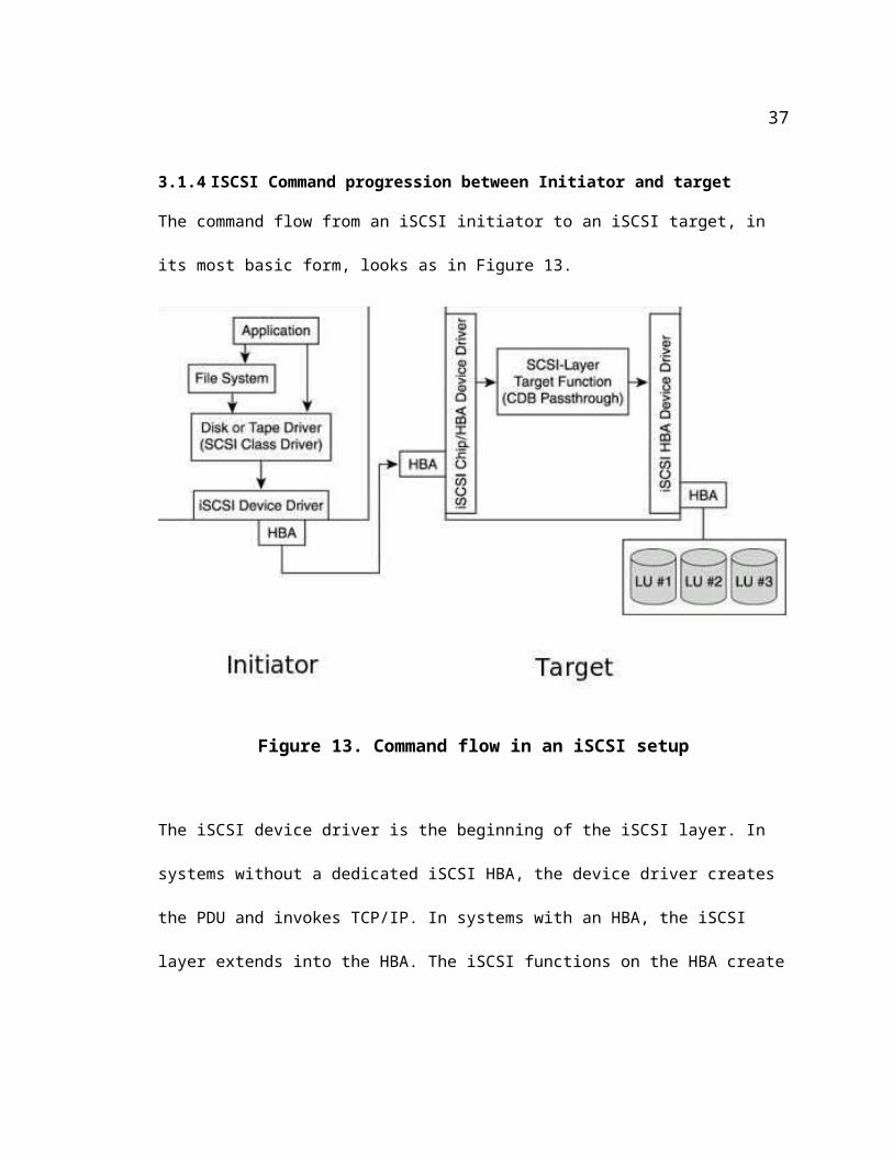
3.1.4 ISCSI Command progression between Initiator and target
The command flow from an iSCSI initiator to an iSCSI target, in its most basic form, looks as in
Figure 13.
Figure 13. Command flow in an iSCSI setup
The iSCSI device driver is the beginning of the iSCSI layer. In systems without a dedicated iSCSI
HBA, the device driver creates the PDU and invokes TCP/IP. In systems with an HBA, the iSCSI
layer extends into the HBA. The iSCSI functions on the HBA create the PDUs. These offloaded
functions in-turn interface with the TCP/IP offload engine, which is also on the HBA.
27

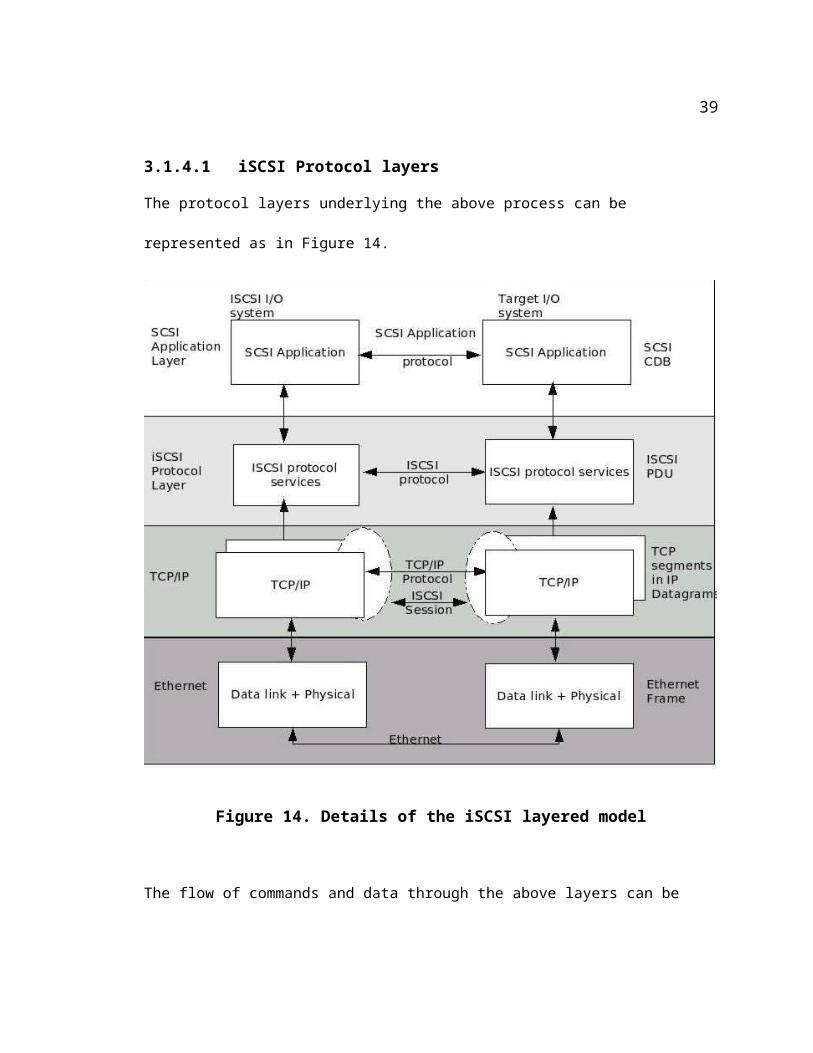
3.1.4.1 iSCSI Protocol layers
The protocol layers underlying the above process can be represented as in Figure 14.
Figure 14. Details of the iSCSI layered model
The flow of commands and data through the above layers can be summarized as follows.
To send data to a storage device, the application of choice invokes a 'write' API on the
initiator. For reasons to be explained later, the current thesis uses the 'sg_dd' utility on the
28
initiator. A typical sg_dd command used in the current thesis looks like
sg_dd if=test_file_100MB.txt of=/dev/scsi/host0/bus0/target0/lun0/disc bs=1024 bpt=1 odir=1 count=102400 skip=0 seek=0
where
if = input file name
of = output file name. In the above example, the device name
is being given, indicating that the file needs to be
copied on to the device.
bs = block size
bpt = blocks per transfer
count = number of blocks of block size given by the ‘bs’
option.
odir = the ioctl O_DIRECT flag. Indicating that the device
needs to be opened for writing with O_DIRECT=1. This
is the preferred way of opening devices
in Linux 2.6. This makes the internal buffers used by
sg_dd to align to a memory page boundary. This memory alignment is required by both raw
devices and block devices that implement O_DIRECT. An
interesting fact to note here is that, during trials, without the odir=1 option, sg_dd
transferred the correct number of bytes. But the
checksum as computed by ‘cksum’ was inconsistent
with that of the input file.
skip = In the input file, start reading from an offset given by the number of blocks set in this option
seek = In the output file, start writinging from an offset given by the number of blocks set in this
option.
29

The API will deliver the 'write' request to the SCSI layer (the SCSI class driver).
Depending on the application, this is sometimes done through the file system. 'sg_dd'
bypasses the file system. The 'cp' command, had it been used to do the 'write's would
deliver through the file system.
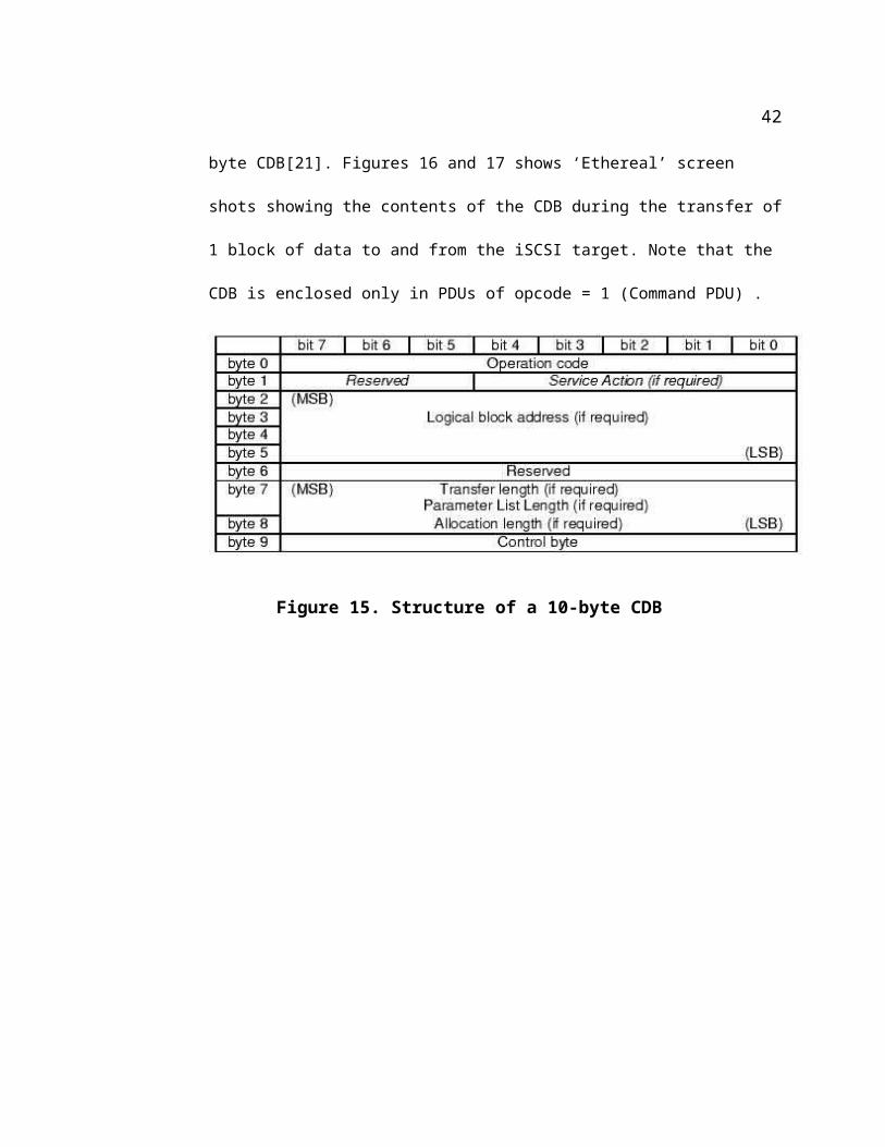
The SCSI class driver builds a Command Descriptor Block (CDB) for the request and
passes it into a device driver in the iSCSI protocol layer. The length of a SCSI CDB
started at 6 Bytes for SCSI-1 and has grown to 16 bytes in SCSI-3. In the current project,
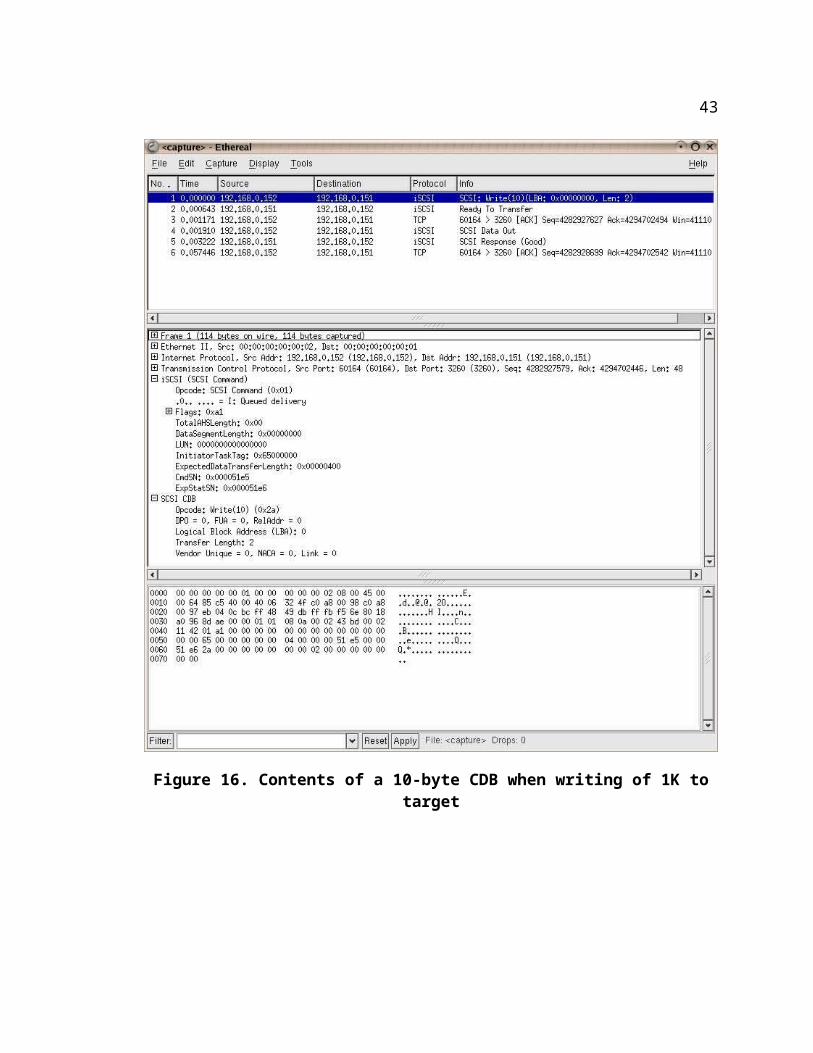
the CDB used by the SCSI sub-system was 10 bytes long. Figure 15 shows the structure
of a 10 byte CDB[21]. Figures 16 and 17 shows ‘Ethereal’ screen shots showing the
contents of the CDB during the transfer of 1 block of data to and from the iSCSI target.
Note that the CDB is enclosed only in PDUs of opcode = 1 (Command PDU) .
Figure 15. Structure of a 10-byte CDB
30
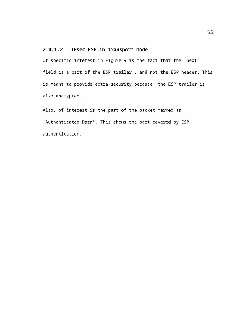
Figure 16. Contents of a 10-byte CDB when writing of 1K to target
31
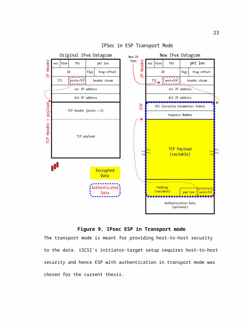
Figure 17. Contents of a 10-byte CDB when reading 1K from target
The iSCSI protocol layer places the CDB and other parameters like the LUN identifier in
an iSCSI PDU and invokes TCP/IP.
TCP breaks up the PDU into multiple segments, according to the segment size, and
32
places a TCP header on them. IP layer in turn places an IP header.
The IP packet will optionally pass through the IPsec layer where the TCP payload and
other headers/trailers are encrypted and authenticated appropriately.
The IP packets are delivered to the Ethernet data link layer which frames the packets in
Ethernet headers and trailers.
At the target the Ethernet frames are stripped off and the remaining is passed into upper
layers.
If employed, IPsec will optionally re-authenticate the data to compare with the checksum
earlier populated in the Authentication header. If found OK, the packets are decrypted
based on the SPI and other details provided in the ESP headers. The IPsec headers and
trailers are removed and the 'protocol' field in the IP header reset.
The TCP and IP layers each check and strip off the respective headers and pass the iSCSI
PDU to the iSCSI layer.
The iSCSI layer extracts the CDB from the PDU and sends it along with other applicable
parameters and data, to the SCSI layer.
The SCSI device will send the SCSI 'write' request and the data to the appropriate LU,
based on the CDB and other information it just received.
3.1.5 Motivation for the project
The following are the reasons for pursuing the current thesis
(1) The importance of backups, and remote storage for security in today's networked world
can hardly be overstated. Of the various options available, iSCSI seemed the most worthy
33
of study because its design smartly makes full use of the universally proven strengths of
existing protocols like TCP, IP, and IPsec, thereby reducing the cost, effort and time of
learning, setup and deployment.
(2) There appears to be a glaring gap in today's iSCSI security configuration employed in
remote storage. The encryption mechanism available in IPsec, while proven, available
and fully acceptable, is being used to protect data only in part of its journey – namely in
transit. Additional costs are being incurred to protect the same data at rest.
(3) There are excellent open source programs to perform the functions of initiator and target .
(4) Any disk – real or virtual, can be made to masquerade as a SCSI disk. This makes the
setup of a test bed very easy.
3.1.6 Stages in iSCSI initiator-target interactions
3.1.6.1 Naming/Addressing
The address of an LU is the combination of its IP address/DNS name and an iSCSI name. The
iSCSI name is that of the Logical unit that is the actual target.
3.1.6.1.1 Formats of iSCSI name
There are two common formats of naming an iSCSI LU.
Eui (Enterprise unique identifier): This format is known as format EUI-64. This is the same
scheme as used to identify FC elements uniquely worldwide. A typical eui looks like
eui.acde482334567abcd
Basically, it has 'eui' followed by 16 hex digits (64 bits). The 64 bits are unique across the world.
34
The first 24 bits (i.e. Acde48) is the unique company ID given to a manufacturer by the IANA
registration authority. The latter 40 bits are created by the manufacturer but unique within a
company.
Iqn (iSCSI qualified name): This is meant to be more user friendly and yet unique world-wide.
This follows the format
iqn.yyyy-mm.dns_name_of_the_manufacturer_in_reverse:unique_name_within_company
A typical example looks like
iqn.1998-03.com.yc.ajax:wonder:jump
The default iSCSI target port number is 3260. This is relied on heavily in the implementation of
the current proposal.
3.1.6.2 Session establishment and management
The logical link or pipe that carries the commands and data from TCP/IP endpoints is called an
iSCSI session. A session consists of at least one TCP/IP connection from the initiator to the
target. To enable enough bandwidth between the two, iSCSI supports the concept of 'Multiple
Connections per Session' or 'MC/S'.
The initiator and target establish and maintain a session between them through the exchange of a
series of commands carried by PDUs. An iSCSI PDU has a basic part of length 48 bytes, known
as a Basic Header Segment (BHS). A PDU can also optionally have an Additional Header
Segment (AHS) of variable length. But, given the options possible within the BHS there is hardly
a need for AHS. A BHS looks as in Table 3.
Byte 0 1 2 3
Bit 0 1 2 3 4 5 6 7 0 1 2 3 4 5 6 7 0 1 2 3 4 5 6 7 0 1 2 3 4 5 6 7
35
Byte 0 1 2 3
0 to 3 .|I| Opcode
4 to 7 Total AHS length
8 to 15 Logical Unit Number (LUN) or Opcode-specific fields
16 to 19 Initiator Task Tag (ITT) or Opcode-specific fields
20 to 31 Opcode-specific fields
32 47 Command Descriptor Block (CDB) or Opcode-specific fields
Table 3: Basic Header Segment (BHS) of an iSCSI PDU Header
The opcode in the BHS stands for 'operation code' and conveys a specific action taking place.
Depending on the type of action permissible, PDUs originate either from the target or the
initiator. Hence the opcodes can be categorized into initiator opcodes or target
opcodes.
Opcodes Numerical value
of opcode
Function
Login request PDU 0x03 (3)
Logout request PDU 0x06 (6)
NOP-Out 0x0 (0)
SCSI Command request 0x1 (1) Encapsulates a SCSI CDB
SCSI Data out 0x05 (5) Output data for writes
Task management function 0x02 (2)
Text Request 0x04 (4) Including SendTargets used in iSCSI discovery
Table 4: Initiator PDUs
36
Opcodes Numerical value of opcode
Asynchronous message 0x32 (50)
Login Response 0x23 (35)
Logout response 0x26 (38)
NOP-in 0x20 (32)
Ready to transfer 0x31 (49)
Reject 0x3f (63)
SCSI Command response 0x21 (33) Can contain status
SCSI Data in 0x25 (37) Input Data from Reads
SNACK request 0xA (10)
Task management function response
0x22 (34)
Text response 0x24 (36)
Table 5: Target PDUsThe key words that will be encountered in the execution of the scheme being proposed in the
current thesis are as follows. For a comprehensive list of keywords, their meanings and
significance please refer to [16].
Keyword Meaning PDU in which the keyword is found
CSG Current Stage. Denote which of the three login stages the login is at
Login
NSG Next Stage in the negotiation phase Login
CID Connection ID The ID of each of the (possibly many) Connections in a session
ITT Initiator Task Tag The ID for the task requested by the Initiator. This field is in all Command PDUs so that the target's response can identify which task they are responding.
Table 6: Keywords in various PDUs
3.1.7 Phases of iSCSI session of interest in the current thesis
The focus of the current thesis is the special handling of user-data during storage and retrieval.
37
So, the discussion below is limited to iSCSI activity during
Session management (Login and Logout)
Writes
Reads
There are 3 phases in the establishment of a session, each indicated by an integer. They are
described in Table 7.
Phase Name
0 Security Negotiations phase (SNP)
1 Login Operational negotiations phase (LONP)
2 Not used
3 Full-feature phase (FFP)
Table 7: Phases in an iSCSI connectionTo establish a login connection, the initiator sends one or more 'Login PDU's to the initiator, and
the target responds with one 'Login Response PDU' for each Login PDU it receives. A typical
exchange of PDUs looks as in Figure 18.
Figure 18, PDU exchange during an iSCSI login
The CSG = SNP refers to the security negotiations phase. The NSG = FFP in the figure refers to
38
the initiator's desire that the next stage be the Full featured phase. The 'T' is the 'Transit bit' that
indicates the senders readiness to switch to the next phase.
3.1.8 Full Feature Phase
During this phase the actual data transfer activity, establishment of additional connections, and
logout takes place. Error handling and recovery also takes place during this phase.
3.2 iSCSI 'Write's
When data is written to the target, it can be sent in 3 ways.
(1) As a part of the Command PDU, as 'Immediate data' : In this case, the header that
accompanies the data is not a 'Data-out' PDU
(2) As a part of the Data-out PDUs , as unsolicited data
(3) In separate Data-out PDUs, sent in response to an 'R2T (ready to transmit) PDU from the
target as solicited data.
The key words used in Table 8 have the following meanings.
R2TSN: The sequence number of R2T PDU. Its value starts at 0 and is incremented by 1
each time an R2T PDU is sent for a specific command. This is a 4-byte field in the PDU
header. The maximum value is 232 – 1.
TTT: The target transfer tag is an ID that the target assigns to each R2T request it sends
to the Initiator. This number, along with the LUN is copied by the Initiator, back into the
out-going data-PDU it sends out in response. This information is used in turn by the
target to identify the data it receives.
ITT: The Initiator Task Tag is the ID given by the Initiator to each task. This value is
39
returned by the target as a part of Data-In PDUs, so that the Initiator can identify the
command that had originally requested the data that just came in the PDU.
F: The Final Bit is set to 1 in the last input data-in PDU of a sequence in a ‘read’. For
Data-out PDUs, this is set to 1 in the last Data-out PDU in response to an R2T.
DataSN: For Data-out PDUs this is the sequence number of the PDUs being sent out in
response to an R2T. It is a 4 byte field. Its starts at 0 and has a maximum value of 2 32. For
Data-in PDUs this is the sequence number of the PDU being sent for the command
identified by the ITT.
ExpDataSN: This field in a SCSI command response PDU indicates the number of
PDUs that the target has sent in response to the command (to which it is now
responding).
Initiator Function PDU Type Target Functionality
Command request (read) SCSI Command (read)(to target)
Receive command and Queue it
Process Old Commands
R2T R2TSN=0,TTT=x (To initiator) Ready for data
R2T R2TSN=1, TTT=y (To initiator) Ready for more data
Send Data for R2TSN 0 SCSI Data-out PDUDataSN = 0, TTT=x, F = 0 (To target)
Receive part of the data for R2T 0
Send Data for R2TSN 0 SCSI Data-out PDUDataSN = 1, TTT=x, F = 1 (To target)
Receive rest of the data for R2T 0
Send Data for R2TSN 1 SCSI Data-out PDUDataSN = 0, TTT=y, F = 1(To target)
Receive the data for R2T 0
SCSI response (To initiator) Finish processing write command and send status (and sense if needed)
Table 8: PDU exchange during an initiator 'write'
40
3.3 iSCSI 'Read's
When data is read from the target, the data is returned in Data-In PDUs. The data is always sent
on the same connection that the request was made on. The exchange of PDUs for a read operation
looks as in Table 9
Initiator Function PDU Type Target Functionality
Command request (read) SCSI Command (read)(to target)
Prepare data transfer
Receive Data SCSI Data-in PDUDataSN = 0, F = 0
Send Data
Receive Data SCSI Data-in PDUDataSN = 1, F = 0
Send Data
Receive Data SCSI Data-in PDUDataSN = 2, F = 1
Send Data
SCSI Response PDU(ExpDataSN = 3)(To initiator)
Send Status and Sense
Table 9: PDU exchange during a an initiator 'read'
3.4 Other PDU exchange relevant to the thesis
The other exchange of data includes R2T PDUs that are sent from the target to request that the
initiator should transmit write data and Command-Status response PDUs, which are generated at
the target and sent to the initiator.
41
Chapter 4
4 Details of the proposed enhancement
The essentials of the scheme, proposed in chapter 1, are as follows.
4.1 When the initiator is sending iSCSI date to the target
In the 'sending side' code of the IPsec layer on the initiator, identify and isolate the user
data in the network traffic going to the target .
Encrypt the rest of the traffic (i.e. All traffic other than the user data) using the standard
IPsec mechanism, using keys generated and managed by the IKE.
Use a custom key, generated independently of the IKE mechanism, to encrypt the user
data. Do not share this key with the target. Save this key for future use to decrypt the
same user-payload when it is returned.
At the target, decrypt the headers using standard IPsec procedure, but do not attempt to
decrypt the user payload. Pass it in the encrypted form to the upper layers so that the
SCSI layer can write it as is (in the encrypted form) to disk.
4.2 When the initiator is trying to read the iSCSI data from the target
On the target, encrypt the headers using standard IPsec mechanism. Do not attempt to encrypt
the user payload.
On the initiator, decrypt the headers using the keys generated and managed by IKE. Use the
42
second, custom key originally used to encrypt the user data, to decrypt the data.
In order to come up with an implementation of this scheme, the pattern of the flow of packets
between the initiator and the target, WITHOUT IPsec was studied to understand the exact
sequence of packets – both when writing to the target and when reading from the target. The
results for the flow when the initiator is writing to the target are shown in Figure 17 – a screen
shot of Ethereal. The pattern when the initiator is reading the same data from the target is shown
in Figure 18.
The study threw a surprise. When the initiator is writing, the user payload is carried as a part of
Data-out PDUs. When the initiator is reading, the user-payload is carried in a plain-vanilla TCP
packet. A packet with a Data-in PDU precedes this packet. Even more surprisingly, the
DataSegmentLength field of the Data-In PDU reflects the length of the user payload, even though
the payload is actually carried by a separate packet. The author could not find an answer for this
behavior nor a way to change it so that a Data-in PDU contains the user payload. Hence the
solution implemented was designed accordingly.
The proposed scheme entails changes to the IPsec-specific code in the linux 2.6 network stack.
To understand how the actual code-modification scheme was arrived at, it helps to recap how data
would be handled by the IPsec code in its native form.
4.3 The native IPsec operation on iSCSI
The IPsec scheme used in the current thesis is called 'transport' mode. This means an ESP header
is inserted between the IP header and the TCP header. The 'protocol' field in the IP header is
changed by the IPsec layer to '50' to indicate the presence of an ESP header following the IP
header. Prior to the 'encryption' part of the IPsec code, this 'protocol' field of the ip header was
43
populated with ‘6’, which is 'TCP'. This information is saved in the IPsec layer, before the
'protocol' field is overwritten with '50'. The saved value will be entered later in the last byte of the
padding that is going to be added at the end of the payload. The iSCSI header together with the
user data forms the payload for the TCP layer. The TCP header plus the iSCSI payload, in turn
forms the payload for the IPsec protocol. This IPsec payload is padded so that the total length (tcp
header + IPsec payload + padding) is an exact multiple of the block size of the encryption
algorithm being used. Care is taken to make sure that the padding is at least 2 bytes long. The last
byte of the padding, is set to the protocol ID saved earlier. The last-but-one byte is set to the total
number of padding bytes (Hence the need to make sure the padding is at least 2 bytes long). The
TCP header, iSCSI header, iSCSI payload and the ESP trailer are together encrypted as one unit.
The padding forms the ESP trailer. An ESP authentication trailer is inserted after the ESP-trailer.
This trailer contains the cryptographic checksum of
Ipheader + esp header + tcp header + iSCSI header + iSCSI data + esp trailer.
The authentication trailer is NOT encrypted.
On the receiving end, the cryptographic checksum is recomputed on the same components as
mentioned earlier. This is compared to the value stored in the ESP authentication trailer. The
packet is rejected if they do not match. If they are found to be matching, the code proceeds to
decrypt the tcp header + iscsi header + iscsi data + esp trailer. After decryption, the esp header
placed between the IP header and the tcp header is removed. The '50' in the 'protocol' field of the
IP header is replaced by the value in the last byte of the padding. The last-but-one byte of the
total payload (which is the length of the padding) gives the number of padding bytes to be
stripped.
The following points are noteworthy in the context of the above process.
44
The above referenced part of the network stack that deals with encryption/decryption and
authentication of data is oblivious to nature of data and contents it is processing. IPsec does not
look into the contents other than to save the 'protocol' field in the IP header. It treats the user
payload and the appropriate headers (depending on whether the mode is 'transport' or 'tunnel')
together as a unit to be encrypted or decrypted.
These aspects cause problems to the proposed scheme of segmented encryption/decryption. The
following section describes how these issues have been managed in implementing the proposed
scheme.
4.4 How the native-IPsec issues are managed in the implementation
The steps in the procedure that is being proposed in this thesis are as follows.
4.4.1 Identify iSCSI data.
This is the first step in the process of treating the iSCSI payload differently from other traffic.
iSCSI is an application layer protocol and hence does not have a protocol ID associated with it.
The only way for the code at the IP layer to identify iSCSI traffic is by the 'destination port' field
in the TCP header in the traffic and by the 'source port' in the TCP header in the traffic going in
the other direction. This requires that the IPsec code parse the contents of each TCP header. The
default port for the iSCSI target is 3260. That number is hard-coded into the current
enhancements.
4.4.2 Encrypt the headers separately
The proposal is to encrypt the non-data part of iSCSI traffic, using IPSec keys generated by the
IKE mechanism. Not all iSCSI packets flowing through the IPSec layer carry the user payload.
45
This means there are going to be two kinds of iSCSI packets in which the headers are encrypted
using the IKE-generated keys
4.4.2.1 iSCSI packets which do not carry any user data.
In this case, the packet is routed through the 'native' IPsec processing, where
the TCP + iSCSI header is treated as a unit. The padding is computed based on the algorithm's
block size and appended at the end of the unit. The unit is encrypted using IKE-keys.
4.4.2.2 iSCSI packets carrying user data.
In these packets, the TCP header and the iSCSI header are again treated as a unit. However, there
is a difference in how they are processed before encryption. The presence of the payload
following the header precludes any padding at the end of the headers. The BHS of the iSCSI
header is fixed at 48 bytes and hence there is no room at the end of the iSCSI header. This means,
any padding needs to go at the end of the TCP header, between the TCP and the iSCSI headers.
To make room for the padding, the TCP header is moved so as to create a gap between the TCP
header and the iSCSI header. The gap is the same size as the number of bytes of intended
padding. Figure 19 demonstrates the procedure.
46
Figure 19. Packet modification under proposed schemeAs mentioned earlier, the presence of an iSCSI header in the same packet as the user-payload
occurs when the data is going from the initiator to the target. In the case when the data is going
from the target to the initiator, there is no iSCSI data, but the concern still remains the same – the
TCP header plus iSCSI header needs to be long enough to be an exact multiple of the encryption
block size. The same idea as earlier is implemented here as well – padding is added at the end of
the TCP header after pushing it ahead by the same number of bytes. In both cases, the 'data offset'
field in the TCP header is updated to reflect the new length.
47
4.4.3 Updating TCP checksums:
The proposed scheme requires re-computation of the TCP checksums
immediately after the custom-key encryption of the payload when the data is going from
the initiator to the target and
immediately after the custom-key decryption of the payload when the data is received by
the initiator from the target
The following is the explanation of the re-computation of the checksum.
4.4.3.1 The sending side in the initiator:
By the time the packet gets to the IPsec layer, the checksum has already been computed in the
TCP layer and populated in the 'check' field of the TCP header. This checksum covered the TCP
header and the payload in the un-encrypted form (At the TCP layer, the user-payload going to the
target is still un-encrypted). In the IPsec layer under the proposed scheme, two changes occur:
(1) The TCP header has possibly changed in length.
(2) The payload is separately encrypted, NOT to be decrypted on the receiving side. This means,
when the payload reaches the TCP layer on the target, it is still in an encrypted form. The
TCP checksum computed on this encrypted payload will be at variance with the earlier
mentioned TCP checksum computed in the TCP layer of the initiator. This will lead to
rejection of the packet. To avoid this situation, on the initiator, the TCP checksum is
recomputed immediately after the user-payload is encrypted but before the TCP header +
iSCSI header combo is encrypted. The TCP header is updated with the new checksum. When
this packet reaches the TCP layer on the target, the TCP header plus iSCSI header will have
been decrypted by the IPsec layer on the target. The payload is still in the encrypted form.
48
Now, if the TCP layer recomputed the checksum, it will match the value contained in the
TCP header (if the transmission was good).
4.4.3.2 The receiving side of the initiator
The converse of this process takes place when the initiator requests the data from the target. In
the TCP layer of the target, the checksum computed will cover the TCP header-iSCSI header
combo and the payload in encrypted form. But this payload gets decrypted in the IPsec layer of
the initiator, after the packet is received. Now, if the TCP layer on the initiator recomputed the
checksum, the value will be at variance with the value that was originally computed by the target.
This will lead to rejection of the packet. To avoid this situation, the checksum is recomputed in
the IPsec layer of the initiator, as soon as the payload is decrypted. The TCP header is updated
with the new value. Now, when the TCP layer on the initiator recomputed the checksum, the
value will match the number contained in the TCP header.
There is a weakness in the described scenario. In the TCP layer on the initiator, the recomputed
checksum is compared NOT with the value originally computed on the target, but with the value
computed on the same host (initiator) in the IPsec layer. Even if the two numbers, the checksum
in the TCP header and the recomputed value, match, it does not really prove that the transmission
between the two hosts was without error. This uncertainty is remedied if ESP-authentication is
used along with encryption. The ESP authentication does indeed compare the checksum values
computed on two different hosts and hence validates the traffic flow.
In the native form, the IPsec code treats TCP header + iSCSI header + iSCSI data as a single unit
and computes the padding required, based on the formula
total length to be encrypted =
49
(tcpheader length + iscsi hedaer length + iscsi data length + 2 +
blksize-1)&~(blksize-1) (where blksize is the block length for the encryption)
The '+2' takes care of the 2 bytes needed at the end of the padding – one for the length of the
padding and the other for the 'protocol' field.
4.4.3.3 Scope of the implemented solution
The solution implemented currently can deal with full blocks and cannot deal with an arbitrary
length that is not an exact multiple of the encryption block size.
(1) If the initiator tries to copy a file of arbitrary length to the target, the IPsec layer on the
initiator runs into the situation where it needs to pad the payload to be an exact multiple of
the block size, as is done in any IPsec encryption. However, the issue here is that under the
new scheme, the payload is not decrypted at the target. As a result, the padding remains with
the payload when latter reaches the iSCSI layer. Inside the iSCSI layer on the target, this can
lead to problems because the total length of the encrypted payload (no including the padding)
is at variance with the DataSegmentLength field in the PDU header. There are two options at
this stage for the iSCSI target code.
o Extract just the number of bytes equal to DataSegmentLength field in the PDU header.
This means the last block of the encrypted payload will be broken. This payload will get
written to the disk by the SCSI layer. Since the last 'chunk' (after all 'full' blocks of block
length are taken away), is no longer complete, this will break the decryption scheme
when the data is read back to the initiator. Also the remaining bytes in the last block i.e.,
the encrypted padding bytes will remain in the targets input buffer and will be treated as a
part of a subsequent buffer.
50
o Instead, the initiator can choose to modify the DataSegmentLength field in the PDU
header, to reflect the additional padding. However, this will cause problems in the target's
iSCSI code because, the target expects a shorter payload. The target has its own internal
record of what size payload was mutually agreed on during session establishment. This
will confuse the target and make it end up rejecting the packet. The target's iSCSI code
can be changed to accept the new length, but this breaks the initiator's code when the
target sends the new length as data received. This is because the initiator has a record of
the agreed-upon packet length too. Simply adding the padding bytes in the sender side of
the initiator is not possible, because the initiator does not deal with character buffers
containing payload. It is passed scatter-gather arrays from the SCSI layer, that it (iSCSI
layer in the initiator) in-turn passes 'down' to the TCP layer. After painstaking attempts to
find a solution to this problem, it was realized that the general case of arbitrarily long
iSCSI packets needs to be studied as a separate problem. It is expected that changes will
be required to the iSCSI initiator as well as the target. Some changes might be required
even to the SCSI layer.
(2) Arbitrarily long files need file-system commands such as 'cp' to write to the target and to read
the target. On studying the packet flow pattern (as shown by Ethereal) corresponding to the
'cp' command, it was discovered that the exchange of PDUs is somewhat counter-intuitive.
Data-in packets from the target to the initiator were observed. It was felt this deserves a
separate, closer study.
For the test bed in the current thesis, it was decided to use files whose length is an integer
multiple of the file system block size. A block size of 1024 was used because, this block size was
the maximum that could also accommodate additional headers and padding in such a way that the
51
total length could still come to be less than the MTU observer in the test bed (1470).
In order to have a predictable flow of packets, unsolicited data, as well as immediate data was
disabled in the configuration file. Figures 20 and 21 show the Ethereal output' for sg_dd 'write'
and 'read' commands, the packet pattern is as follows.
52

4.4.3.4 Ethereal Packet pattern for write to target
Figure 20. Packet sequence between initiator and target during a 'write'
53
4.4.3.5 Ethereal Packet pattern for read from target
Figure 21. Packet sequence between initiator and target during a 'read'
Because of the peculiarity observe rd in the data-in packets, it was felt that the opcode is not
always an indicator of payload. The solution is to use the sg_dd utility to write data to the target
disk from the initiator. This was done because the focus was on getting a proof-of-concept to
54
work. More effort is needed to identify the exact sequence of packets when using file commands.
Chapter 5
5 Performance data and analysis
The sections below include the performance data for several runs of iSCSI data transfer between
the UML initiator and target, for a variety of file sizes. [Note : Data for similar runs on the
implementation test bed will be included ASAP]. The reasons for developing the solution first on
the virtual machines are included below.
5.1 Role of User Mode Linux
As mentioned earlier, the proposed scheme for asymmetric efficient IPsec was implemented first
on a development test bed using virtual machines. The obvious benefit of using virtual machines
is that it eliminates the need for multiple physical machines, processors, hard disks etc – thus
greatly reducing the cost of a development test bed. Use of virtual machines also meant that the
initial setup was easier because the author just had to start with one copy of the root file system,
load the necessary utilities, and then start-up multiple virtual machines, using the ‘Copy-on-
wrote’ (COW) scheme. Subsequently, two separate copies of the root file system were made as an
extra precaution during back ups. Even so, the COW files were still used with each of the file
systems to allow room for any ‘disastrous’ configuration errors. The COW scheme meant there
was more room for trial-and-error. There were several occasions during the development process
55
on which the author could restore the file system to a known state simply by deleting a corrupted
COW file. The more direct benefits of UML virtual machines to the actual implementation of the
proposed scheme can be summarized as follows.
The ability to debug iSCSI modules as a part of UML meant that the author could trace
the path of data packets all the way from the application layer into the IP layer. This
helped greatly in understanding how iSCSI works and interacts with the other layers.
As an extension of the above capability, both of the iSCSI hosts – i.e. the Initiator and the
Target could be debugged simultaneously (using two different gdb instances). This meant
that the movement of a data packet could be traced all the way from the data layer on one
host (Initiator or target), to the data layer of the other host (target or Initiator
respectively). This was felt to be the single biggest benefit of using virtual machines
during the development process.
The development process involved restarting the hosts innumerably. The duration it takes
to reboot a virtual machine is less than that to restart a real machine and hence this
indirectly contributed to speeding up the development process.
Figure 22 shows a schematic of the virtual test bed used in this project.
56
Host : running linux 2.6.12.1Physical memory : 640 M. Processor = 2 Ghz Celeron
80 GB Hard disk
ISCSI Initiator
UML instance running linux 2.6.12.1 andopen-iscsi 0.4-434
uml specs : 'physical memory' : 256M
File system : 1.4 GB
IP = 192.168.0.152
ISSI target
UML instance running linux 2.6.12.1 andiscsitarget-0.4.11
uml specs : 'physical memory' : 256M
File system : 1.4 GB
IP = 192.168.0.151
Bridge and TUN/TAP interfacesBridge created using brctl
TUN interfaces created using tunctlPhysical Host IP = 192.168.0.100
Figure 22. A schematic of the UML test bed used in the current thesis
5.2 Performance Analysis
The goals of the proposed scheme are
To eliminate the situations where data exists in non-encrypted form outside of the Initiator.
To achieve the above while minimizing the number of times the data is encrypted/decrypted
57
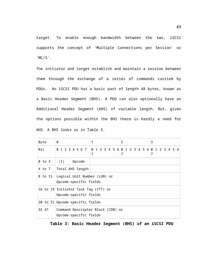
To maximize security by encrypting/authenticating all the headers used during transmission.
The effectiveness of the proposed scheme is compared to the scenario where the data is
transmitted using IPsec and encrypted and decrypted at the target site. This scenario has earlier
been shown in Figure 2. Since the current implementation has been designed to process only
1024 bytes of data in each TCP segment, the same payload size will be applied for both cases.
It should be noted that the scheme shown in Figure 4 is a slightly different option to approximate
the proposed scheme. However, the numbers for that scheme will be identical to the one for
scheme in Figure 2 (detailed below in Table 10).
5.2.1 Computational details of the available scheme
The available alternative involves the following computations, given in terms of 16 byte blocks –
the block size for the AES encryption algorithm. Table 10 reports the respective durations taken
for encryption and decryption during the round-trip of a single TCP segment of 1024 bytes. In the
table, the TCP header is shown as consisting of two 16-byte blocks. This has been done for two
reasons.
In the proposed scheme, the TCP header + iSCSI header unit needs to be an integer multiple of
the block size. Given that the iSCSI header is fixed at 48 bytes (which happens to be an integer
multiple of 16 bytes), even if the TCP header were to have the smallest possible size of 20 bytes,
the TCP header still needs to be padded with of 12 bytes so that the sum of TCP header size +
iSCSI header size comes to be an integer multiple of the block size. Incidentally, the TCP header
on the virtual machines was indeed observed to be 32 bytes long.
For the other scheme, even if the TCP header were to be the smallest possible size of 20 bytes,
the fact remains that the total of TCP header + iSCSI header + payload needs to be padded to
58
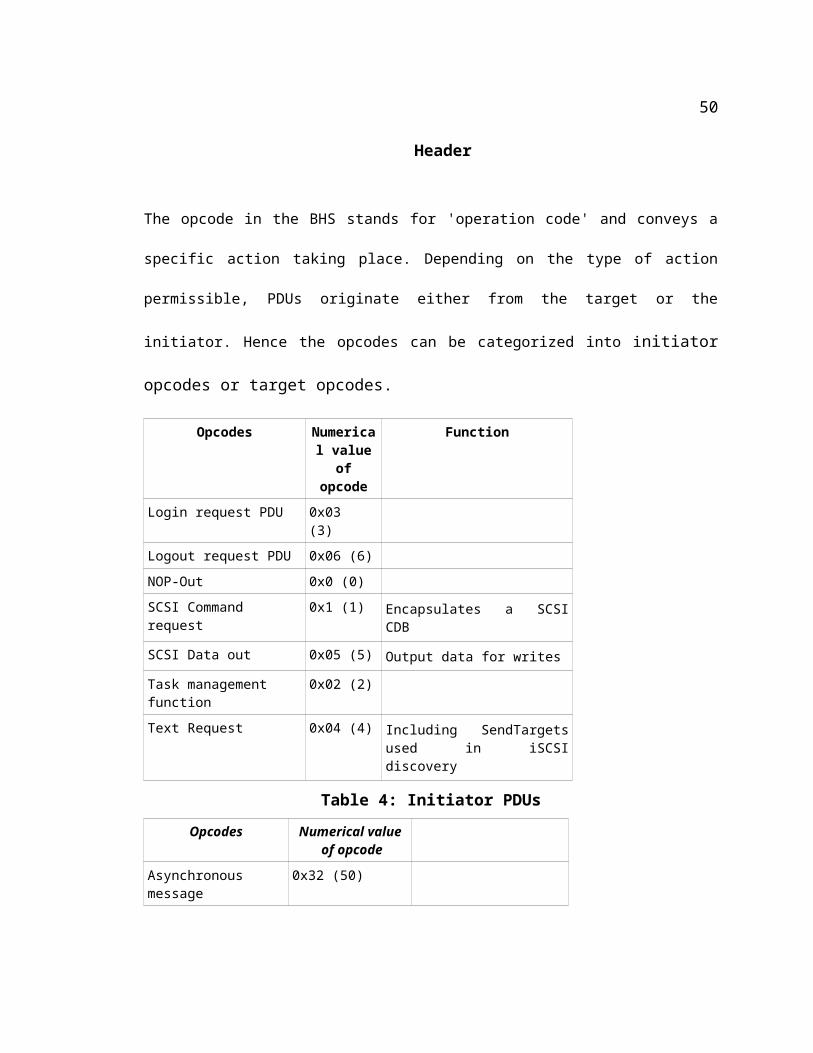
become an integer multiple of 16 bytes. The total number of 16-byte blocks does not change.
From the above numbers, it is obvious that the proposed scheme is expected to take only 35%
(138/394) of the other scheme. This gain in efficiency, combined with the fact that the data never
is left unencrypted outside of the initiator, makes the proposed scheme attractive.
Portion of the packet
Available alternative Proposed scheme
Number of 16-byte
blocks encrypted
or decrypted
Where and how encrypted/decrypted
Number of 16-byte blocks
encrypted or
decrypted
TCP header 2 Initiator , encrypted as part of IPsec
2 Initiator ,encrypted as part of IPsec
iSCSI header 3 Initiator, encrypted as part of IPsec
3 Initiator, encrypted as part of IPsec
Pay-load 128 Initiator, encrypted as part of IPsec
128 Initiator, encrypted as part of IPsec
TCP Header 2 Target, decrypted as part of IPsec
2 Target, decrypted as part of IPsec
iSCSI Header 3 Target, decrypted as part of IPsec
3 Target, decrypted as part of IPsec
Payload 128 Target, decrypted as part of IPsec
0 No decryption at target
Payload 128 Target, encrypted as part of third-party re-encryption
0 No encryption
Payload 128 Target, decrypted in preparation for transfer to Initiator
0 No decryption
TCP header 2 Target ,encrypted as part of IPsec
2 Target ,encrypted as part of IPsec
iSCSI header 3 Target, encrypted as part of IPsec
3 Target, encrypted as part of IPsec
Payload 128 Target, encrypted as a part of IPsec during transmission to Initiator
0 No encryption
Payload 128 Initiator, decrypted as a part of IPsec
128 Initiator, decrypted as a part of IPsec
TCP Header 2 Initiator, decrypted as part of 2 Initiator, decrypted as part
59
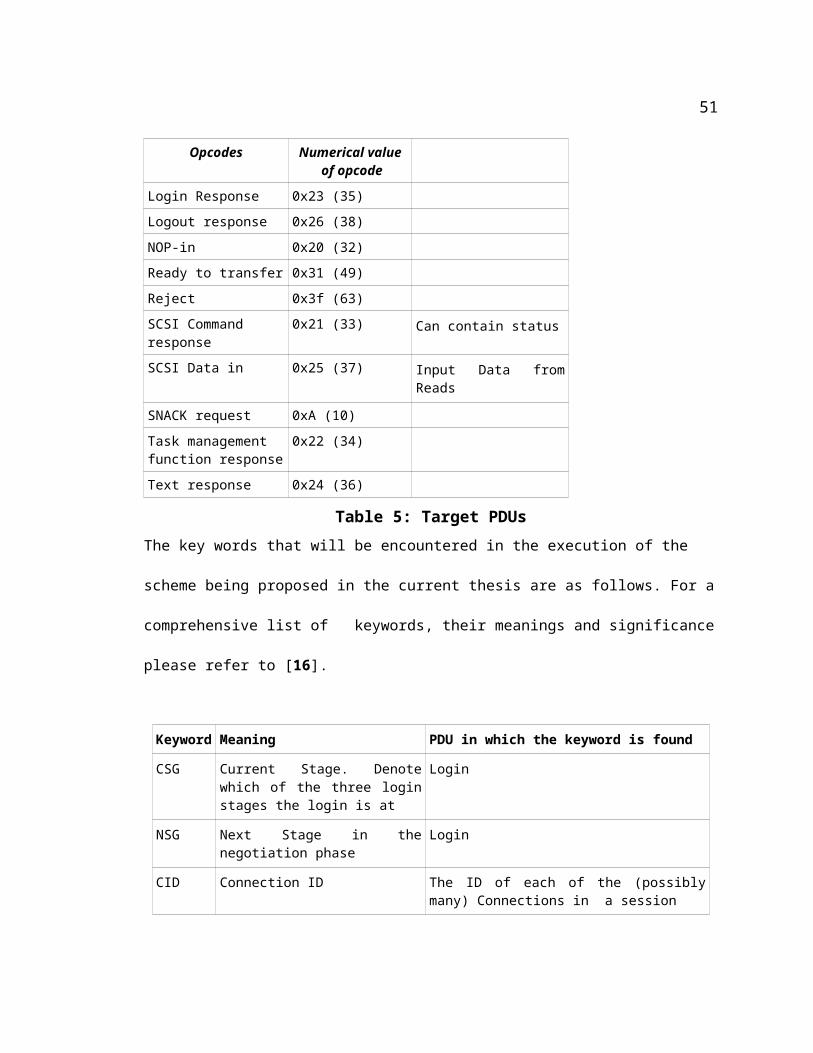
IPsec of IPsec
iSCSI Header 3 Initiator, decrypted as part of IPsec
3 Initiator, decrypted as part of IPsec
Total 394 Encrypted
138 Encrypted
394 Decrypted
138 Decrypted
Table 10. Number of 16-byte blocks encrypted during round-trip of 1 TCP segment
5.3 Performance data of the proposed scheme on a UML test bed
Tables 11-16 shows the actual data for data transfer of files of various sizes. Where the numbers
are given in the form ‘a+b = c’, ‘a’ and ‘b’ are for writing and reading respectively. In some
columns of the tables for 1K and 10K, there is a second set of numbers shown highlighted in
gray. These numbers are from runs where a new run after some duration of inactivity resulted in
slightly higher numbers. Repeated attempts at the same runs produced numbers that are consistent
with the other (non-grayed-out) numbers in the same column. Similar variation in numbers has
NOT been noticed for file sizes higher than 10K. These numbers are included here only for
completeness. These have not been included while plotting the graphs in Figures 17-18.
Time->(sec)
SampleRun
Writing + Readingwithout any encryption
(A)
Writing+ Reading with
Native IPsec
(B)
Encryptionwith
OpenSSL
(C)
Decryption with
OpenSSL
(D)
(B + C + D)
Writing + Readin gunder
Proposedscheme
1 0.03 + 0.03 = 0.06
0.1 + 0.06 = 0.16
0.04 + 0.04 = .08
0.12 + 0.07= 0.19
0.103 0.104 0.286
0.397
0.12 + 0.06 = 0.18
2 0.04 + 0.03 = 0.07
0.09 + 0.07 =0.16
0.03 + 0.04 = 0.07
0.12 + 0.07 = 0.19
0.085 0.088 0.243
0.363
0.16 + 0.05 = 0.21
3 0.03 + 0.03 = 0.06
0.12 + 0.08 = 0.20
0.05 + 0.03 = 0.08
0.07 + 0.08 = 0.15
0.089
0.087
0.086
0.086
0.323
0.255
0.06 + 0.05 = 0.11
60
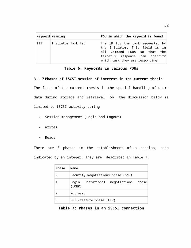
Time->(sec)
SampleRun
Writing + Readingwithout any encryption
(A)
Writing+ Reading with
Native IPsec
(B)
Encryptionwith
OpenSSL
(C)
Decryption with
OpenSSL
(D)
(B + C + D)
Writing + Readin gunder
Proposedscheme
4 0.03 + 0.06 = 0.09 0.04 + 0.06 = 0.1 0.087 0.087 0.274 0.1 + 0.04 = 0.15
5 0.04 + 0.05 = 0.09 0.04 + 0.05 = 0.09 0.084 0.091 0.265 0.04 + 0.05 = 0.09
6 0.05 + 0.03 = 0.08 0.17 + 0.086 = 0.256 0.088 0.092 0.436 0.06 + 0.06 = 0.12
7 0.06 + 0.03 = 0.09 0.17 + 0.03 = 0.2 0.085 0.087 0.372 0.05 + 0.05 = 0.1
Table 11. Performance of the UML test bed when transferring a 1K file
Time-->(sec)
SampleRun
Writing + Readingwithout any encryption
(A)
Writing+ Reading with
Native IPsec
(B)
Encryptionwith
OpenSSL
(C)
Decryption with
OpenSSL
(D)
(B + C + D)
Writing + Reading under
Proposedscheme
1 0.08 + 0.07 = 0.15
0.10 + 0.11 = 0.21
0.08 +0.06 = 0.14
0.14 + 0.09= 0.23
0.11
0.11
0.087
0.1
0.337
0.44
0.08 + 0.09 = 0.17
2 0.07 + 0.05 = 0.12
0.13 + 0.08 = 0.21
0.12 + 0.09 = 0.21 0.09 0.091 0.391
0.391
0.09 + 0.06 = 0.15
3 0.07 + 0.05 = 0.12
0.12 + 0.09 = 0.21
0.06 + 0.06 = 0.12
0.11 + 0.12 =0.23
0.086
0.091
0.093
0.09
0.299
0.411
0.11 + 0.06 = 0.17
4 0.08 + 0.05 = 0.13
0.13 + 0.08 = 0.21
0.07 + 0.06 = 0.13
0.14 + 0.15 = 0.29
0.085 0.088 0.303
0.463
0.17 + 0.07 = 0.24
5 0.07 + 0.07 = 0.14 0.09 + 0.07 = 0.16 0.095 0.09 0.345 0.11 + 0.07 = 0.18
6 0.09 + 0.07 = 0.16 0.09 + 0.11= 0.2 0.089 0.086 0.375 0.12 + 0.09 = 0.21
7 0.09 + 0.06 = 0.15 0.09 + 0.08=0.17 0.085 0.091 0.346 0.11 + 0.08 = 0.19
Table 12., Performance of the UML test bed when transferring a 10K file
61
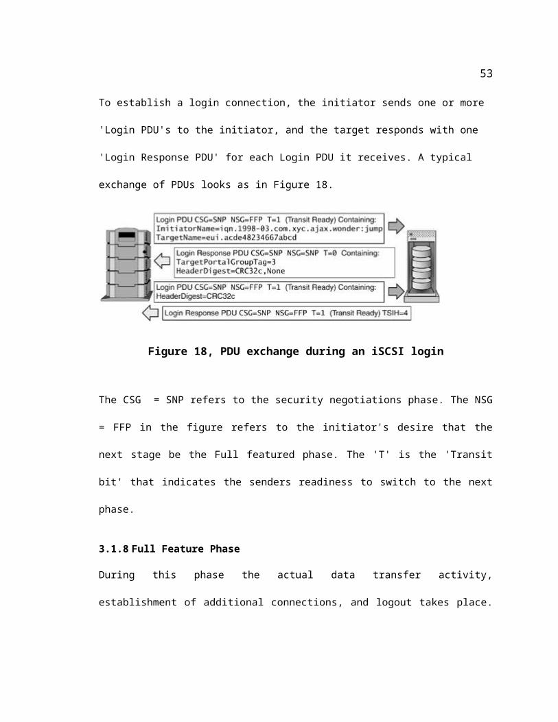
Time-->(sec)
SampleRun
Writing + Readingwithout any encryption
(A)
Writing+ Reading with
Native IPsec
(B)
Encryptionwith
OpenSSL
(C)
Decryption with
OpenSSL
(D)
(B + C + D
)
Writing + Reading under
Proposedscheme
1 0.45 + 0.32 = 0.77 0.54 + 0.38= 0.92 0.168 0.138 1.266 0.53 + 0.36 = 0.89
2 0.49 + 0.37 = 0.86 0.59 + 0.40 = 0.99 0.105 0.112 1.207 0.55 + 0.35 = 0.90
3 0.47 + 0.34 = 0.81 0.58 + 0.37 = 0.95 0.101 0.095 1.146 0.56 + 0.37 = 0.93
4 0.54 + 0.28 = 0.82 0.59 + 0.35 = 0.94 0.093 0.123 1.156 0.51 + 0.34 = 0.85
5 0.48 + 0.32 = 0.8 0.51 + 0.34 = 0.85 0.094 0.097 1.041 0.49 + 0.35 = 0.84
6 0.48 + 0.29 = 0.77 0.56 + 0.4 = 0.96 0.099 0.097 1.156 0.5 + 0.33 = 0.83
7 0.44 + 0.27 = 0.71 0.52 + 0.32 = 0.84 0.1 0.103 1.043 0.5 + 0.35 = 0.85
Table 13. Performance of the UML test bed when transferring a 100K file
Time->(sec)
SampleRun
Writing + Readingwithout any encryption
(A)
Writing+ Reading with
Native IPsec
(B)
Encryptionwith
OpenSSL
(C)
Decryption with
OpenSSL
(D)
(B + C + D)
Writing + Reading under
Proposedscheme
1 4.51 + 2.44 =6.95 4.57 + 3.09 = 7.66 0.305 0.210 8.175 4.92 + 3.76 =8.68
2 4.95 + 2.65 = 7.6 4.84 + 3.62 = 8.46 0.194 0.185 8.839 4.68 + 3.11 = 7.79
3 4.02 + 2.7= 6.72 4.55 + 3.09 = 7.64 0.183 0.19 8.013 5.00 + 3.18 = 8.18
4 3.87 + 2.44 = 6.31 4.71 + 3.13 = 7.84 0.182 0.184 8.206 4.6 + 3.03 = 7.63
5 3.90 + 2.54 = 6.44 4.53 + 3.03 = 7.56 0.265 0.64 8.465 4.62 + 3.01 = 7.63
6 3.89 + 2.47 = 6.36 4.55 + 3.12 = 7.67 0.189 0.193 8.052 4.63 + 3.04 = 7.67
7 3.99 + 2.39 = 6.38 4.62 + 2.87 = 7.49 0.181 0.189 7.86 4.61 + 3.0 = 7.61
Table 14. Performance of the UML test bed when transferring a 1M file
62

Time->(sec)
SampleRun
Writing + Readingwithout any encryption
(A)
Writing+ Reading with
Native IPsec
(B)
Encryption
withOpenSSL
(C)
Decryption with
OpenSSL
(D)
(B + C + D)
Writing + Reading under
ProposedScheme
1 38.26 + 23.77 = 62.03 47.49 + 32.75 = 80.24 0.941 1.065 82.246 50.37 + 33.61 = 83.98
2 40.91 + 25.04 = 65.95 46.25 + 33.14 = 79.39 0.956 1.072 81.418 46.13 + 32.96 = 79.09
3 38.55 + 25.52 = 64.02 44.97 + 29.57= 74.54 0.957 1.051 76.548 50.04 + 33.16 = 83.2
4 38.38 + 23.85 = 62.23 47.27 + 30.15 = 77.42 0.925 1.061 79.406 46.11 + 30.36 = 76.47
5 52.78 + 24.84 = 77.62 44.89 + 29.76 =74.65 0.992 10.57 76.699 46.29 + 29.95 = 76.24
6 38.37 + 24.68 = 63.05 45.14 + 30.23 = 75.37 0.945 1.196 77.511 46.28 + 30.12 = 76.4
7 38.50 + 24.05 = 62.55 44.92 + 28.82 = 73.74 0.976 1.015 75.731 46.26 + 30.19 = 76.45
Table 15. Performance of the UML test bed when transferring a 10M file
Time->(sec)
SampleRun
Writing + Readingwithout any encryption
(A)
Writing+ Reading with
Native IPsec
(B)
Encryptionwith
OpenSSL
(C)
Decryption with
OpenSSL
(D)
( B + C + D)
Writing + Reading underProposedScheme
1 394.0 + 254.84=648.84
458.09 +294.93= 753.02
17.7 18.2 788.92
476.71 + 305.94 = 782.65
2 375.99 + 236.14 = 612.04
450.77+ 296.49 = 747.17
12.91 18.7 778.78
472.86 + 310.0 = 782.86
3 374.78 + 235.16 =609.94
461.72 + 297.74 =759.46
14.71 16.47 790.64
468.79 + 308.44 = 777.23
4 385.76 + 238.69 = 624.45
469.47 + 302.66 = 772.13
13.063 18.827 804.02
461.16 + 304.32 = 765.48
5 423.02 + 250.52 = 673.54
453.46 + 293.55 = 747.01
13.027 16.8 776.837
461.71 + 300.58 = 762.29
6 389.05 + 245.27 = 634.32
454.48 + 302.09 = 756.57
13.16 18.15 787.88
461.62 + 301.53 = 763.15
63
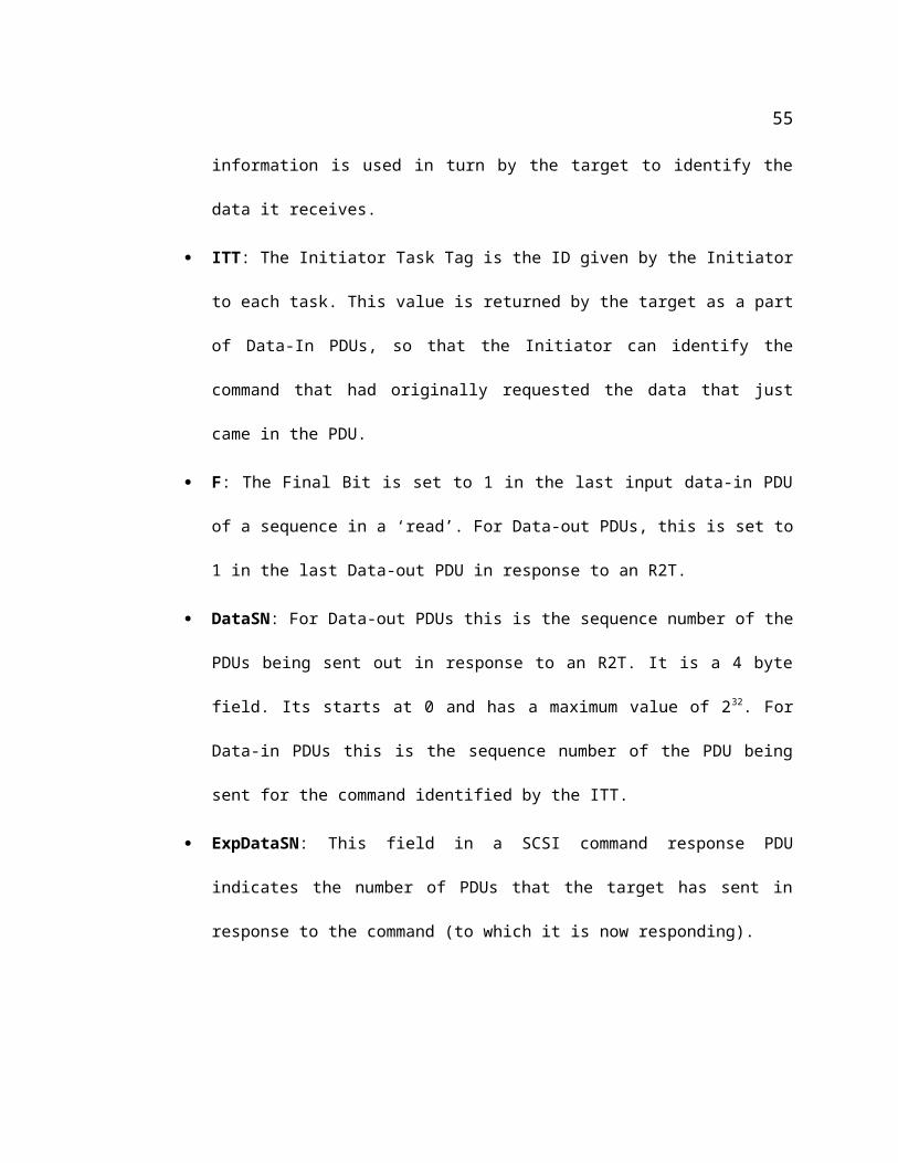
Time->(sec)
SampleRun
Writing + Readingwithout any encryption
(A)
Writing+ Reading with
Native IPsec
(B)
Encryptionwith
OpenSSL
(C)
Decryption with
OpenSSL
(D)
( B + C + D)
Writing + Reading underProposedScheme
7 387.07 + 241.55 = 628.62
452.52 + 302.28 = 754.8
13.462 18.59 786.852
461.27 + 301.28 = 762.55
Table 16. Performance of the UML test bed when transferring a 100M file
Figures 17-18 show the same results in a graphical form. To accommodate the wide range of
durations (about a tenth of a second for a 1K file to about 800 seconds for 100MB), the plots are
shown against two logarithmic Y-axes. The durations for file sizes 1K, 10K and 100K are to be
read against the Y-axis on the left, where as those for 1M, 10M and 100M are to be read against
the right Y-axis.
64
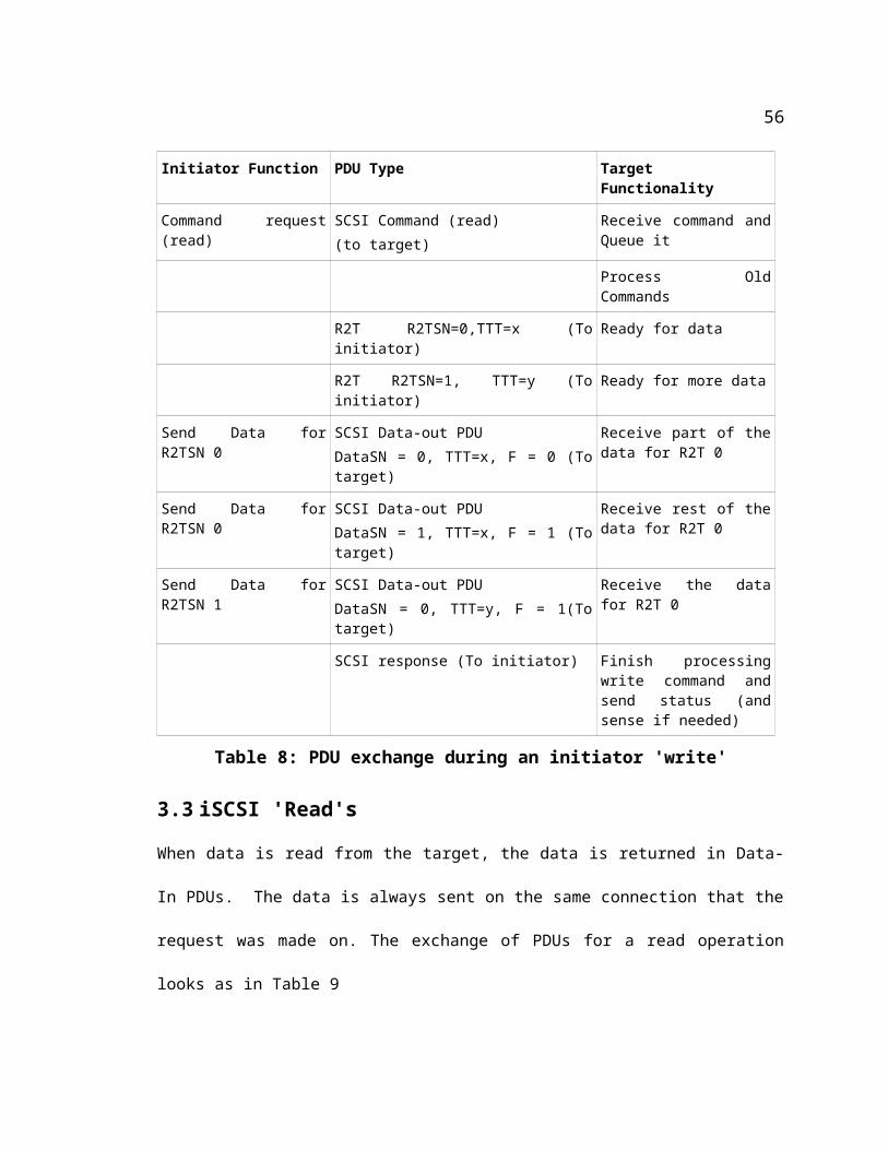
Write & Read with IPSecEncrypt & Decrypt at Target
0.18 0.21 0.11 0.14 0.09 0.12 0.1
0.44 0.391 0.4110.173
1.226 1.207 1.146 1.156 1.041 1.156 1.043
0.3460.3750.345
8.175 8.839 8.013 8.206 8.465 8.052 7.86
788.92 778.78 790.64 804.02 776.837 787.88 786.852
75.73177.51176.699
79.40676.54882.246 81.418
0
1
2
3
4
5
6
7
1 2 3 4 5 6 7Sample
Tim
e in
sec
1
10
100
1000
Tim
e in
Sec
1K10K100K1M10M100M
Figure 23. Performance under currently available alternative
65
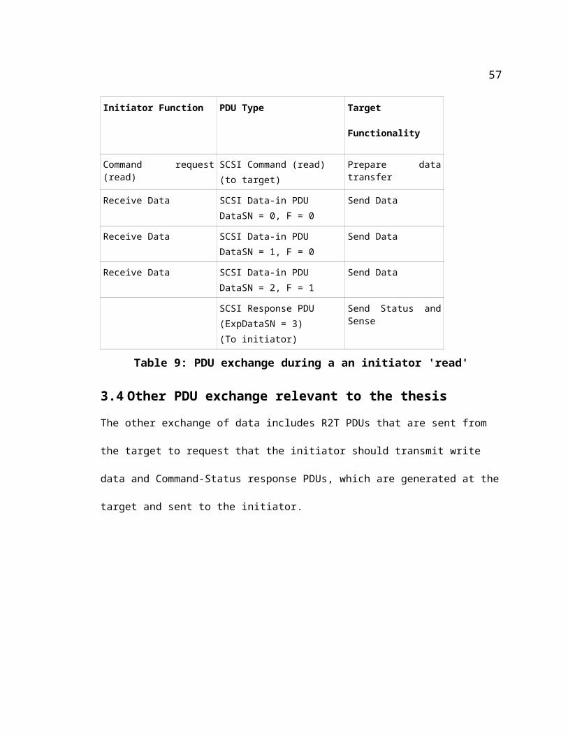
Write & Read under theProposed Scheme
0.11 0.14 0.09 0.12 0.100.17 0.15 0.17 0.240
0.89 0.9 0.93 0.85 0.84 0.83 0.85
0.18 0.21
0.18 0.21 0.19
8.68 7.79 8.18 7.63 7.63 7.67 7.61
782.65 782.86 777.23 765.48 762.29 763.15 762.55
79.0983.98 83.2 76.47
76.24 76.4 76.45
0
1
2
3
4
5
6
7
1 2 3 4 5 6 7Sample
Tim
e in
sec
1
10
100
1000
Tim
e in
Sec
1K10K100K1M10M100M
Figure 24. Performance under the proposed scheme
Figure 25 shows the performance of the various schemes of iSCSI communication - no IPsec,
IPsec + client-site encryption/decryption, proposed scheme as a function of the file size. The Y
axis is logarithmic. For the sake of clarity, the average durations for each file size have been used
in this plot.
66
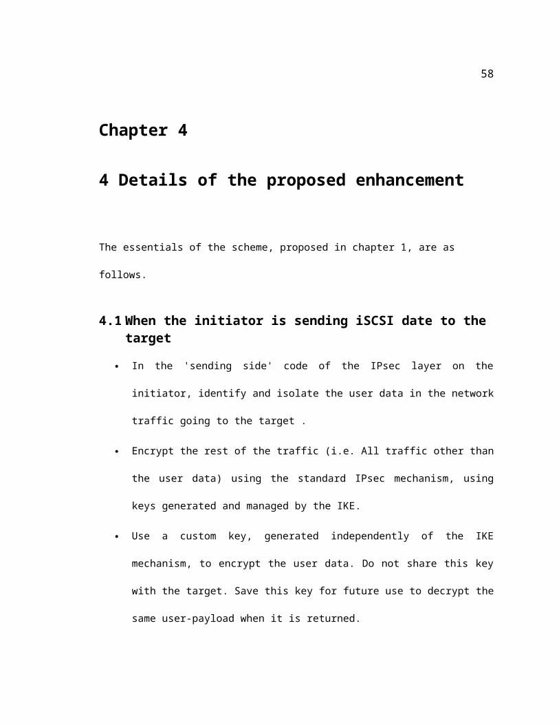
0.100
1.000
10.000
100.000
1000.000
1K 10K 100K 1M 10M 100M
File Size
Tim
e in
Sec
onds
W/O Ipsec Ipsec + Encrypt/Decrypt Proposed
Figure 25. Performance of the different schemes of iSCSI communication
5.4 Analysis
Results in Figures 24-26 show the durations for the proposed scheme being closer to the case
when there is no IPsec in communication, than to the case where there is IPsec +
encryption/decryption. Hoever, they do not reflect the expected gains in performance. This is
attributed to the fact that the results are for data transfer between virtual machines which are
affected by factors like numerous context switches. The fact that the ‘Write’s on the Initiator can
also affect the performance of ‘read’s on the target is also a point to note.
67
Chapter 6
6 Lessons Learnt
o iSCSI target and Initiator are not specifically designed for use with virtual machines. So,
changes needed to be made to the make files to make them work with the UMLs.
o The iSCSI_transport code within the linux kernel is configured, by default, to build the code
as a static part of the kernel. The iSCSI initiator contains modified versions of the same
functionality, built as a module. Attempts to install this module resulted in the error
/usr/src/iscsi/open-iscsi/svn/kernel/scsi_transport_iscsi.ko':
-1 File > exists
because the static (in-kernel) part of the iSCSI_transport code, already loaded, had a conflict
with the module that is trying to load. This prevented the iSCSI initiator from running at all.
This problem was remedied by changing the kernel config spec so that the kernel’s version of
the iSCSI_transport code was built as a module (‘m’ instead of a ‘*’ in .config).
o Debugging modules in user mode linux proved to be very tricky. Portions of the procedure
were found documented on the internet. Some involved the use of a physical machine while
68
the others involved the use of kgdb which is not as user-friendly as gdb. However, none were
actually capable of debugging modules of a third-party application like iSCSI Initiator or the
iSCSI target using virtual machines. The procedure needed to be arrived at after putting
together the various tools detailed in Appendix D.
o The Re-computation of TCP checksums as described in the proposed scheme was yet another
obscure issue that involved thorough debugging of the linux network stack to understand why
all iSCSI traffic from the initiator to the target was getting rejected. A related issue was the
actual function calls to make to perform the re-computation. Given the numerous options
available in linux for computation of TCP checksums under various conditions, figuring out
the right combination of functions to use involved extensive trial and error.
o During the initial efforts to develop the implementation, the author tried to make the target
disk accessible to the initiator by using the ‘mount’ command to mount the target iSCSI disk
at a mount point on the initiator and then using the ‘cp’ command to transfer the file from the
initiator to the target. Both of these commands result in internal file system calls that result in
a counter-intuitive (to the uninitiated) sequence of iSCSI packets. (After repeated queries in
the open-iSCSI group, the author came to know of such a behavior). That is why a decision
was made to use the ‘dd’ utility. However, even the use of ‘dd’ did not help entirely because
it does not offer enough control on the granularity of data attempted to be transferred. This
resulted, again, in an unpredictable pattern of packet flow. Queries on the open-iscsi.org
group led the author to use the ‘sg_dd’ utility with the ‘bpt=1’ option (blocks per transfer = 1)
that resulted in a predictable flow pattern of packets.
o Another issue that took a long time to resolve was the intricate way the payload size is used
in the SCSI layer, iSCSI initiator and iSCSI target and IPsec layer. This issue came into
69
relevance when, initially, attempts were made to transfer ‘cp’ files of arbitrary length between
the initiator and the target. These resulted in the data passing the TCP layer but getting
rejected in the iSCSI layer. Stepping through the code revealed that the padding of data for
encryption in the IPsec layer on the initiator (under the modified scheme) was resulting in a
data length that is at variance with what the iSCSI initiator and target understood to be
passing between them. This recognition led to the decision to transfer only payloads that are
integer multiples of the encryption block size. How ever, there are some other issues
regarding the actual data sizes communicated between the SCSI layer and iSCSI layer that
are not yet understood by the author. Hence the decision was made to transfer data only in
multiples of 1K sizes.
70
Chapter 7
7 Future Directions
The author has the following future efforts to suggest
Enhance the current implementation to transfer files of arbitrary sizes between the Initiator
and the target. (This will need further study of interaction between SCSI layer and the iSCSI
Initiator and the iSCSI target).
Implement the proposed scheme on a TOE – with both iSCSI and IPsec integrated.
Implement a /proc file system-based effort to enter the customized keys and Initial vectors.
(Currently, the second key is hard-coded in the kernel). Additional criteria like the user ID
can also be included, so that users can deploy different keys. Such an effort should also
include a way to securely store the custom keys (and criteria) used during the iscsi ‘write’s so
that they can be retrieved as needed during ‘read’s.
Currently, all iSCSI traffic within a TCP segment is identified by the iscsi target port number
(3260). The payload is specifically identified with the additional help of its size being 1K.
Attempts can be made if the packets can be ‘mark’ed with the help of utilities like ‘netfilter’
so that the packets can be identified with less effort in the IPsec layer. An even better way
71
might be to integrate such criteria into IPsec’s ‘Security Association’/’Security Policy’
management mechanism (the ‘setkey’ utility for hard-coded keys, ‘raccoon’ for dynamic
IKE) in such a way that handling-specific-to-application-layer-protocol , becomes an inherent
part of the IPsec mechanism.
A point to note is that the proposed scheme only expects to have a custom key available for
‘writes’ and have the same key accessible for ‘read’s. There is no restriction that this key
needs to be static (hard-coded from the application layer) or be the same all time. There can
be several ways of starting with a fixed ‘base’ portion of a custom key and dynamically
enhancing the key by appending details like a time stamp, or the user ID, or the file name. As
long as there is a way of saving the final version of the key, such a scheme will actually
enhance security by constantly changing the customized key.
An enhancement to an IDE like DDD to take over an existing gdb session will help the UML
user community debug modules more easily. In fact such an enhancement will help the linux
development community in general. An explanation is given below.
It is currently possible to use the ‘DDD’ utility in conjunction with gdb to debug UMLs
(this the the author’s preferred way to debug UMLs). The use of a tool like DDD (or
Eclipse) improves the inter-activeness of a debug session significantly and therefore
improves the development process. However, the current limitation is that, such a tool
cannot be used with UMLs when there is a need to support and debug modules (linux-
native, or third party). Hence the author could use only ‘gdb’ with UMLs to debug
modules. The author came to know that DDD currently has the limitation that it cannot
‘take over’ an existing gdb session – it can only spawn a gdb session. However, the
author received indications from one of the current maintainers of DDD that correcting
72
this issue will not be a major effort.
73
Chapter 8
8 Conclusions
An efficient asymmetric IPsec protocol enhancement was proposed for reducing the processing
time and improving security of secure iSCSI based online-backup systems. A development test
bed were constructed using UML virtual machines to facilitate the development/debugging of
IPsec kernel/networking code. A benchmark test bed with two real PCs were installed with the
new modified IPsec module and a set of experiments are planned to collect the performance data
of the proposed system. The analysis of the data from the UML test bed does not show the
expected performance gains but running the same trials on actual machines is expected to show
significant performance gains with the proposed scheme. An invention disclosure was filed.
8.1 Advantages of the current approach
The proposed scheme is independent of the encryption and authentication algorithms used.
(The setup was tested with AES as well as 3DES).
Under the proposed scheme, the target machines do not perform many computations. As
such, they need not be as fast as the initiator.
8.2 Limitations of the current approach
This approach needs kernel modifications and probably makes a software approach even less
74

attractive.
Incremental updates to files is difficult.
75
9 Bibliography
1. http://www.computerworld.com/securitytopics/security/story/0,10801,110148,00.html
2. http://www.backupusa.com/Security-BUSA.htm
3. Tom Clark , “IP SANs: A Guide to iSCSI, iFCP, and FCIP Protocols for Storage Area Net-
works”. Addison Wesley Professional
4. http://www.iscsistorage.com/ipstorage.htm
5. RFC2401
6. Marrone, Nancy why you need (more) storage security, http://www.infostor.com/Articles/Ar-
ticle_Display.cfm?Section=Articles&Subsection=Display&ARTICLE_ID=173287
7. http://www.unixwiz.net/techtips/iguide-ipsec.html
8. Kolesnikov, Oleg “Building Linux Virtual Private Networks (VPN)” New Raiders 2002
9. Doraswamy, Naganand; Harkins, Dan “IPsec – the new security standard for internet” Pren-
tice Hall”, page 44
10. http://www.kame.net/
11. http://www.openswan.org/
12. http://strongswan.org/
13. http://www.freeswan.org/
14. http://ipsec-tools.sourceforge.net/
76
15. Friedhelm Schmidt, “SCSI Bus & IDE Interface – Protocols, applications and programming”,
Chapter 10
16. Friedhelm Schmidt, “SCSI Bus & IDE Interface – Protocols, applications and programming”,
Chapter 12
17. Hufferd, John L. “iSCSI: The Universal Storage Connection”, Addison Wesley Professional,
2002
18. http://www.alacritech.com/html/012802.html,
19. http://www.netapp.com/library/tr/3241.pdf]
20. [http://www.rtcmagazine.com/sup_files/rtc0505_sbe04.pdf]
21. David Deming, Solution Technology “SCSI – The protocol for all Storage Architectures”,
October 2005 , SNIA
22. Hufferd, John L. “iSCSI: The Universal Storage Connection”, Addison Wesley Professional,
2002, chapter 4
77
10 APPENDIX A : User Guide of AIPsec
10.1 Setting up IPsec
The following sections describe the process to compile the tools needed to setup IPsec, generate
the SPD/SAD entries and set up IPsec for communication between hosts.
10.1.1 Build the setkey utility
'setkey' is a part of the ipsec-tools package . Ipsec-tools-0.3.3. This is the utility used to read
configuration files and generate IPsec keys in manual mode. The instructions to build it are given
below. For details, refer to [23].
10.1.2 Package dependencies for setkey
Make sure the following packages are available on the system
flex-2.5.4a-30.i386.rpm
openssl-0.9.7a-23.i386.rpm
openssl-devel-0.9.7a-23.i386.rpm
krb5-devel-1.2.7-14.i386.rpm
10.1.3 Commands to build setkey
tar xvf ipsec-tools-0.3.3.tar
cd ipsec-tools-0.3.3
78
./configure --prefix=/usr --sysconfdir=/etc --with-openssl=yes -with-kernel-
headers=full_path_to_the_linux_kernel_source/include
make all'
make install
10.1.4 Generating a key
dd if=/dev/random count=24 bs=1 | xxd -ps
Typical output looks like
24+0 records in
24+0 records out
9751b98c10403af4c12f24ebee88bb1a95e56f7e19927709
prefix the above key with a 0x and use it in the configuration file
entries below.
10.1.5 Generating SAD and SPD entries using the setkey utility on target
The configuration file used on the target is shown below. It shows the use of AES for encryption
The key size used for encryption for this thesis is 192 bits (24 bytes). (AES can also optionally
use key sizes of 128 bits or 256 bits). AES uses an encryption block size of 128 bits (as opposed
to a block size of 64 bits by 3DES).. The authentication algorithm used here is hmac-md5. It
requires a 128 bit key. The man page for setkey lists all the encryption and authentication
algorithms supported by IPSec. It also lists the key sizes. The target in this case has an IP address
of 192.168.0.151. The Initiator has the IP address 192.168.0.152.
#!/usr/sbin/setkey -v -f
79
# Flush the SAD and SPDflush;spdflush;# creating SAD entries add 192.168.0.152 192.168.0.151 esp 0x201 -E aes-cbc 0x7aeaca3f87d060a12f4a4487d5a5c3355920fae69a96c831 -A hmac-md5 "authentication!!" ; add 192.168.0.151 192.168.0.152 esp 0x301 -E aes-cbc 0x49fce5b82ff7acc4d6aded691a0f5f9a65e18861ad4b66bf -A hmac-md5 "authentication!!" ; # Creating SPD entries spdadd 192.168.0.152 192.168.0.151 any -P in ipsec esp/transport//require; spdadd 192.168.0.151 192.168.0.152 any -P out ipsec esp/transport//require ;
The command
setkey -f above_file_name
generates the corresponding SAD and SPD entries.
10.1.6 Displaying SAD entries on the target
The command
setkey -D
displays the entries in the SAD, For the above configuration, the generated entries look like
192.168.0.151 192.168.0.152 esp mode=transport spi=769(0x00000301) reqid=0(0x00000000) E: aes-cbc 49fce5b8 2ff7acc4 d6aded69 1a0f5f9a 65e18861 ad4b66bf A: hmac-md5 61757468 656e7469 63617469 6f6e2121 seq=0x00000000 replay=0 flags=0x00000000 state=mature created: Apr 2 12:53:21 2006 current: Apr 2 12:53:24 2006 diff: 3(s) hard: 0(s) soft: 0(s) last: hard: 0(s) soft: 0(s) current: 0(bytes) hard: 0(bytes) soft: 0(bytes)
80
allocated: 0 hard: 0 soft: 0 sadb_seq=1 pid=754 refcnt=0
192.168.0.152 192.168.0.151 esp mode=transport spi=513(0x00000201) reqid=0(0x00000000) E: aes-cbc 7aeaca3f 87d060a1 2f4a4487 d5a5c335 5920fae6 9a96c831 A: hmac-md5 61757468 656e7469 63617469 6f6e2121 seq=0x00000000 replay=0 flags=0x00000000 state=mature created: Apr 2 12:53:21 2006 current: Apr 2 12:53:24 2006 diff: 3(s) hard: 0(s) soft: 0(s) last: hard: 0(s) soft: 0(s) current: 0(bytes) hard: 0(bytes) soft: 0(bytes) allocated: 0 hard: 0 soft: 0 sadb_seq=0 pid=754 refcnt=0
10.1.7 Displaying SPD entries on the target
The command
setkey -PD
displays the entries in the SPD. For the above configuration they look like
192.168.0.152[any] 192.168.0.151[any] any in ipsec esp/transport//require created: Apr 2 12:53:22 2006 lastused: lifetime: 0(s) validtime: 0(s) spid=8 seq=1 pid=755 refcnt=1192.168.0.151[any] 192.168.0.152[any] any out ipsec esp/transport//require created: Apr 2 12:53:22 2006 lastused: lifetime: 0(s) validtime: 0(s) spid=9 seq=0 pid=755 refcnt=1
81
10.1.8 Generating SAD and SPD entries using the setkey utility on initiator
The configuration file on 192.168.0.152, for communication with 192.168.0.151 looks like
#!/usr/sbin/setkey -v -f # Configuration for 192.168.0.152 # Flush the SAD and SPDflush;spdflush; add 192.168.0.152 192.168.0.151 esp 0x201 -E aes-cbc 0x7aeaca3f87d060a12f4a4487d5a5c3355920fae69a96c831 -A hmac-md5 "authentication!!" ; add 192.168.0.151 192.168.0.152 esp 0x301 -E aes-cbc 0x49fce5b82ff7acc4d6aded691a0f5f9a65e18861ad4b66bf -A hmac-md5 "authentication!!" ; # Security policiesspdadd 192.168.0.151 192.168.0.152 any -P in ipsec esp/transport//require;
spdadd 192.168.0.152 192.168.0.151 any -P out ipsec esp/transport//require ;
setkey -f the_above_file_name will generate the SAD and SPD entries.
10.1.9 Displaying the SAD entries on the initiator
'setkey -D' shows the SAD entries as
192.168.0.151 192.168.0.152 esp mode=transport spi=769(0x00000301) reqid=0(0x00000000) E: aes-cbc 49fce5b8 2ff7acc4 d6aded69 1a0f5f9a 65e18861 ad4b66bf A: hmac-md5 61757468 656e7469 63617469 6f6e2121 seq=0x00000000 replay=0 flags=0x00000000 state=mature created: Apr 2 13:10:51 2006 current: Apr 2 13:10:54 2006 diff: 3(s) hard: 0(s) soft: 0(s) last: hard: 0(s) soft: 0(s)
82
current: 0(bytes) hard: 0(bytes) soft: 0(bytes) allocated: 0 hard: 0 soft: 0 sadb_seq=1 pid=721 refcnt=0
192.168.0.152 192.168.0.151 esp mode=transport spi=513(0x00000201) reqid=0(0x00000000) E: aes-cbc 7aeaca3f 87d060a1 2f4a4487 d5a5c335 5920fae6 9a96c831 A: hmac-md5 61757468 656e7469 63617469 6f6e2121 seq=0x00000000 replay=0 flags=0x00000000 state=mature created: Apr 2 13:10:51 2006 current: Apr 2 13:10:54 2006 diff: 3(s) hard: 0(s) soft: 0(s) last: hard: 0(s) soft: 0(s) current: 0(bytes) hard: 0(bytes) soft: 0(bytes) allocated: 0 hard: 0 soft: 0 sadb_seq=0 pid=721 refcnt=0
10.1.9.1 Displaying SPD entries on the initiator
'setkey -DP' shows the SPD entries as192.168.0.151[any] 192.168.0.152[any] any in ipsec esp/transport//require created: Apr 2 13:10:51 2006 lastused: lifetime: 0(s) validtime: 0(s) spid=8 seq=1 pid=722 refcnt=1192.168.0.152[any] 192.168.0.151[any] any out ipsec esp/transport//require created: Apr 2 13:10:51 2006 lastused: lifetime: 0(s) validtime: 0(s) spid=9 seq=0 pid=722 refcnt=1
83
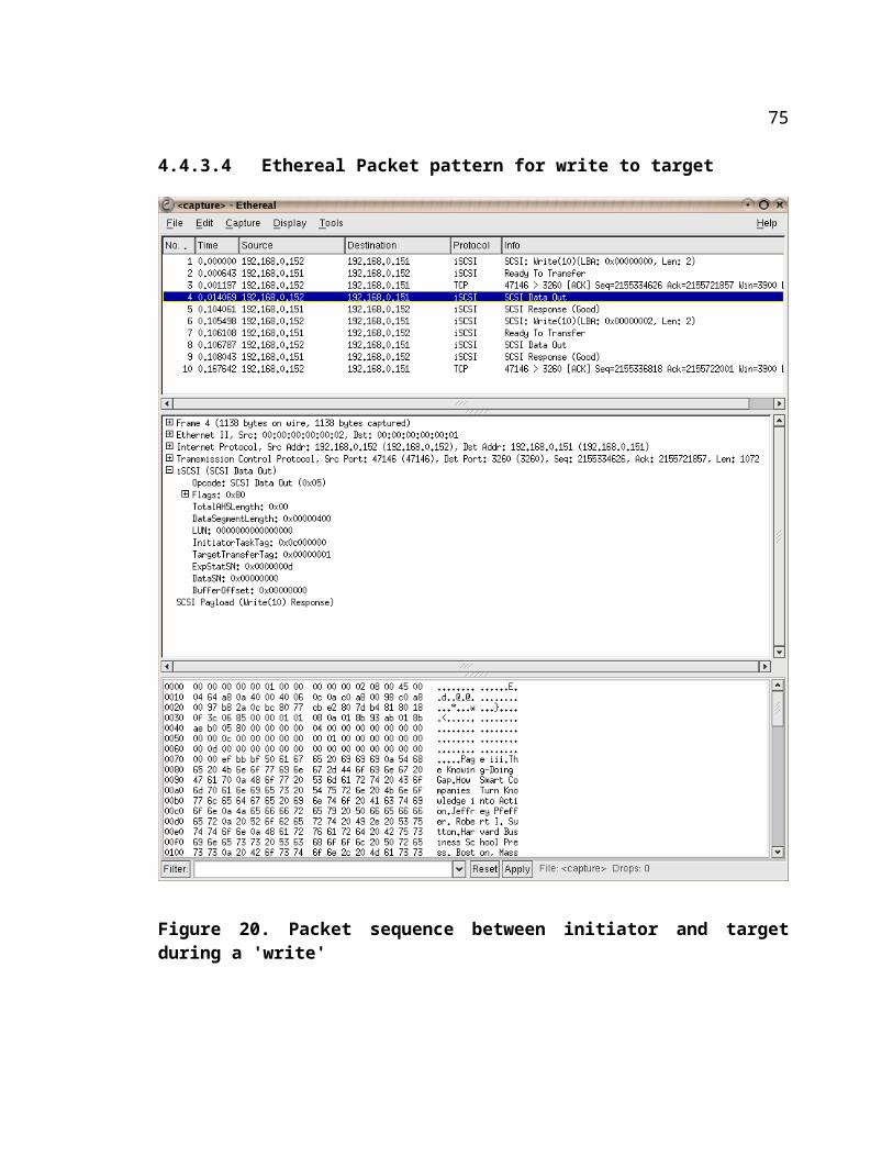
10.2 Appendix B : Running the iSCSI target program
10.2.1 Installing target on a host machine
tar xvf iscsitarget-0.4.11.tarcd iscsitarget-0.4.11
make all
This builds the two binaries ietd and ietadm in iscsitarget-0.4.11/usr directory.
Also builds the module iscsi_trgt.ko in the iscsitarget-0.4.11/kernel directroy
make install
This installs the two binaries in /usr/sbin directoryThe module is installed in /lib/modules/`uname -r`/kernel/iscsi
10.2.2 Installing target on a UML
This procedure involves mounting the target uml rootfs on a mount point on the host
mount -o loop target_UML's_rootfs /mnt/mount_point
tar xvf iscsitarget-0.4.11.tarcd iscsitarget-0.4.11
KERNELSRC := /path_leading_to_iscsi_target_uml/linux-2.6.12.1export INSTALL_MOD_PATH := /mnt/mount_point
modify the 'install' target in the Makefile as follows
install: kernel/iscsi_trgt.ko usr/ietd usr/ietadm @install -vD usr/ietd $(INSTALL_MOD_PATH)/usr/sbin/ietd @install -vD usr/ietadm $(INSTALL_MOD_PATH)/usr/sbin/ietadm if [ -f /etc/debian_version ]; then \ install -vD -m 755 etc/initd/initd.debian $(INSTALL_MOD_PATH)/etc/init.d/iscsi-target; \ elif [ -f /etc/redhat-release ]; then \ install -vD -m 755 etc/initd/initd.redhat $(INSTALL_MOD_PATH)/etc/init.d/iscsi-target; \ elif [ -f /etc/gentoo-release ]; then \ install -vD -m 755 etc/initd/initd.gentoo $(INSTALL_MOD_PATH)/etc/init.d/iscsi-target; \ elif [ -f /etc/slackware-version ]; then \
84
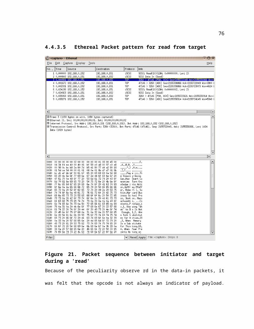
install -vD -m 755 etc/initd/initd $(INSTALL_MOD_PATH)/etc/rc.d/iscsi-target; \ else \ install -vD -m 755 etc/initd/initd $(INSTALL_MOD_PATH)/etc/init.d/iscsi-target; \ fi @eval `sed -n 's/#define UTS_RELEASE /KERNELRELEASE=/p' $(KERNELSRC)/include/linux/version.h`; \ install -vD kernel/iscsi_trgt.ko \ $(INSTALL_MOD_PATH)/lib/modules/$$KERNELRELEASE/kernel/iscsi/iscsi_trgt.ko -depmod -aq
make all
This builds the two binaries ietd and ietadm in iscsitarget-0.4.11/usr directory.
Also builds the module iscsi_trgt.ko in the iscsitarget-0.4.11/kernel directroy
make install
This installs the two binaries in $INSTALL_MOD_PATH/usr/sbin directoryThe module is installed in $(INSTALL_MOD_PATH)/lib/modules/`uname -r`/kernel/iscsi
umount the UML root file system and prepare to run the uml.
10.2.3 Running the target
Copy the file iscsitarget-0.4.11/etc/ietd.conf into /etc/init.d
Cd /etc/init.d
Make appropriate changes to ietd.conf (sample included in the DVD)
Execute the command iscsi-target start
85
10.3 Appendix C: Running iSCSI Initiator program
10.3.1 Installing the initiator in the host machine
This step needs root access.
untar open-iscsi-0.4-434.tarcd open-iscsi-0.4-434/kernelcat backward-compile-2.6.12.patch | patch -p0 <-- assuming kernel 2.6.12.xcd .. make all
This results in the two binaries - 'iscsid' and 'iscsiadm' being built in open-iscsi-0.4-434/usr.
Also, the two modules iscsi_tcp.ko and scsi_transport_iscsi.ko are built in
open-iscsi-0.4-434/kernel.
make install
results in the two binaries being installed to /usr/sbin
The two modules are installed to /lib/modules/`uname -r`/kernel/drivers/scsi
10.3.2 Installing the initiator in a virtual machine
This step requires that the Initiator UML's root file system be mounted on
a directory on the host machine.
mount -o loop initiator_UML's_rootfs /mnt/uml_mount_point
tar xvf open-iscsi-0.4-434.tar
cd open-iscsi-0.4-434
Add the following entries to the Makefile
KSRC=/path_leading_to_the_initiator_UML's_kernel_code/linux-2.6.12.1INSTALL_MOD_PATH=/path_to_the_initiator_UML's_root_file_system
86
modify the 'install' target in the Makefile to the following
install: kernel/iscsi_tcp.ko kernel/scsi_transport_iscsi.ko usr/iscsid usr/iscsiadm @install -vD usr/iscsid $(INSTALL_MOD_PATH)/usr/sbin/iscsid @install -vD usr/iscsiadm $(INSTALL_MOD_PATH)/usr/sbin/iscsiadm if [ -f /etc/debian_version ]; then \ install -vD -m 755 etc/initd/initd.debian /etc/init.d/open-iscsi; \ elif [ -f /etc/redhat-release ]; then \ install -vD -m 755 etc/initd/initd.redhat $(INSTALL_MOD_PATH)/etc/init.d/open-iscsi; \ fi install -vD kernel/iscsi_tcp.ko $(INSTALL_MOD_PATH)/lib/modules/2.6.12.1-bs7y/kernel/drivers/scsi/iscsi_tcp.ko install -vD kernel/scsi_transport_iscsi.ko $(INSTALL_MOD_PATH)/lib/modules/2.6.12.1-bs7y/kernel/drivers/scsi/scsi_transport_iscsi.ko -depmod -aq
cd open-iscsi-0.4-434/kernelcat backward-compile-2.6.12.patch | patch -p0 <-- assuming kernel 2.6.12.xcd .. make all
This results in the two binaries - 'iscsid' and 'iscsiadm' being built in open-iscsi-0.4-434/usr.
Also, the two modules iscsi_tcp.ko and scsi_transport_iscsi.ko are built in
open-iscsi-0.4-434/kernel.
make install
results in the two binaries being installed to /$INSTALL_MOD_PATH/usr/sbin
The two modules are installed to $INSTALL_MOD_PATH/lib/modules/`uname -r`/kernel/drivers/scsi
umount the UML rootfs and prepare to run the UML
10.3.3 Running the iscsi initiator
Copy the file open-iscsi-0.4-434/etc/iscsid.conf into /etc/ of the machine on which the initiator is
running. Make sure to set the value shown in bold, as shown. A '#' at the beginning of an entry
indicates commenting out. For detailed information about the meaning of the parameters, refer to
[17]. Of specific interest are the username and password entries. If not commented, the values for
87
these should match the values set in the target config file . Commenting these out means any user
can interact with the target.
node.session.iscsi.ImmediateData = No
For the scheme being proposed to work, payload packets going to and from the initiator to the
target should belong only to the command sent. If ImmediateData' is set to 'On' there is a
possibiliy that data from other commands is transmitted after the 'Write' or 'Read' command is
given.
The header digest and the Data digest have been disabled (set to 'None') for this project because
the data is going to be secured by ipsec encryption.
The ' MaxRecvDataSegmentLength ' parameter
For the scheme being proposed in this thesis to work, it is imperative that there be an iscsi header
in front of the data payload going from the initiator to the target. For this to happen, the data
payload needs to be small enough to fit within the mss. If the payload is not sent in such units, the
second(and subsequent) chunk(s) of a given payload unit, will not have a header. This makes it
difficult to identify payload correctly and encrypt.
10.3.3.1 Sample iSCSI Initiator Config file
#
# Open-iSCSI default configuration.
# Could be located at /etc/iscsid.conf or ~/.iscsid.conf
#node.active_cnx = 1
node.startup = manual#node.session.auth.username = dima
88
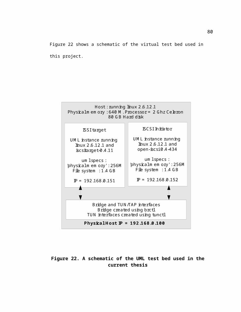
#node.session.auth.password = aloha
node.session.timeo.replacement_timeout = 0
node.session.err_timeo.abort_timeout = 10
node.session.err_timeo.reset_timeout = 30
node.session.iscsi.InitialR2T = Yes
node.session.iscsi.ImmediateData = No#node.session.iscsi.FirstBurstLength = 262144
#node.session.iscsi.MaxBurstLength = 16776192
node.session.iscsi.DefaultTime2Wait = 0
node.session.iscsi.DefaultTime2Retain = 0
node.session.iscsi.MaxConnections = 0
node.session.iscsi.HeaderDigest = Nonenode.session.iscsi.DataDigest = Nonenode.session.iscsi.MaxRecvDataSegmentLength = 1024node.cnx[0].iscsi.MaxRecvDataSegmentLength = 1024
10.3.3.2 Sequence of commands to run iSCSI Initiator
cd /lib/modules/2.6.12.1-bs7y/kernel/drivers/scsimodprobe scsi_modmodprobe sd_modmodprobe sgmodprobe scsi_transport_iscsiiscsid -c /etc/iscsid.conf -f -d10&modprobe iscsi_tcpiscsiadm -m discovery --type sendtargets --portal 192.168.0.151:3260 -d10
89
10.4 Appendix D: Compiling UMLs, setting up bridge and debugging kernel modules with UML
The basic instructions to build and run a static (no dynamically loaded modules) UML binary are
available in [Frank's thesis] and so, shall not be repeated here. Given below, are instructions to
build a uml binary with support for dynamically loaded modules. The instructions also show how
to debug the modules. This knowledge comes in very handy because third party software like
iscsitarget and iscsi initiator build modules that need to be included in the machine (physical or
virtual) hosting the software .
10.4.1 Building and installing uml modules
The '.config' file used to build the uml version of the linux kernel is included in the dvd. The
instructions to build the modules are the same as for a host system. (i.e. say 'yes' 'Loadable
Module support' and any options below it, in 'menuconfig'). To install the modules, however, the
steps are as follows.
mount -o loop root_fs_file /mnt/uml_mount_point
cd uml_source_tree_top_level_directorymake ARCH=um modules_install INSTALL_MOD_PATH=/mnt/uml_mount_point
10.4.2 Debugging uml modules
The information presented here is based on scripts and instructions collected from various sources
(and duly modified for the current context). This includes the following steps.
90
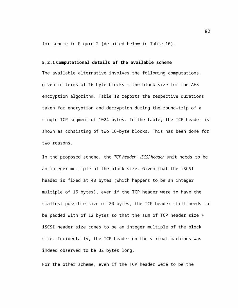
10.4.2.1 Perl script to setup ground for debugging modules in gdb
The perl scripts 'ttyalloc1' and 'ttyalloc2' are included in the dvd. Open an xterm and run the script
'ttyalloc1' as 'exec ttyalloc1'. This creates the file 'uml1.tty' in the same directory with the name of
the pseudo terminal that has been opened up. (An example looks like /dev/pts/2). The enclosed
sample is configured for 'uml1' being the iscsitarget.
The script ttyalloc2 needs to be executed similarly in a separate xterm, to open a terminal for
running uml2 (the second UML instance – for the iscsi initiator.
an 'expect' script to attach a debugger session to the uml
In a different xterm, run the included umlgdb_uml1 to spawn a 'screen' session that runs a 'gdb'
command configured to run the uml session for the iscsi target. It should be noted the script starts
a uml session in the xterm in which 'exec ttyalloc1' was run earlier. However, when the script
completes execution (in the other xterm), there is no 'visible' gdb session to interact with. The
user is just returned to the shell prompt. To interact with the gdb session perform the next step.
'screen' command to attach to the gdb (and uml) session
The command “screen -ls” does not create a screen session but prints the list of 'pid.tty.host'
strings for all the 'screen' sessions on the host. A typical result set looks like
22627.pts-10.localhost (Dead ???) 12600.pts-10.localhost (Dead ???) 28688.pts-5.localhost (Dead ???) 18936.pts-10.localhost (Dead ???) 17060.pts-6.localhost (Dead ???) 24531.pts-4.localhost (Detached)
91
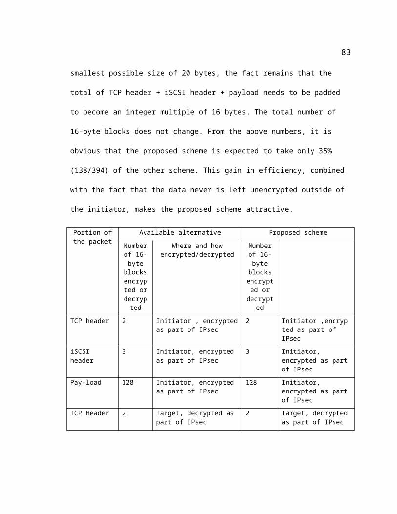
There can be more than one 'detached' screens. The user needs to identify the desired
detached screen based on process id. To attach to the screen , run the following command
screen -r 'desired_pid.tty.host_string
i.e. In this example, it is screen -r 24531.pts-4.localhost
This attaches to the gdb session running the uml (which is actually running in the other xterm). A
ctrl-c in this window brings the gdb prompt.
In the xterm running the screen session, the user needs to watch out for the followig prompt and
take appropriate action for the uml session to continue.
---Type <return> to continue, or q <return> to quit---
sometimes, this can happen even before the screen session is attached to. When this happens, the
uml session in the separate xterm seems to hang, When that happens, attach to the screen session
using the 'screen -r ' command and look for the above prompt.
10.4.2.2 Using GDB to debug modules
At this point, for each UML virtual machine, we have one xterm running the uml session and
another xterm containing the gdb session associated with the uml session. The following steps set
up the modules to be debugged.
Given the name of the module to be debugged as the lone parameter, the file get_add-symbol-
file_cmd file within the file system of both uml1 and uml2, generates the text to add as a
command at the gdb prompt. A typical example looks as follows
get_add-symbol-file_cmd iscsi_trgt
92
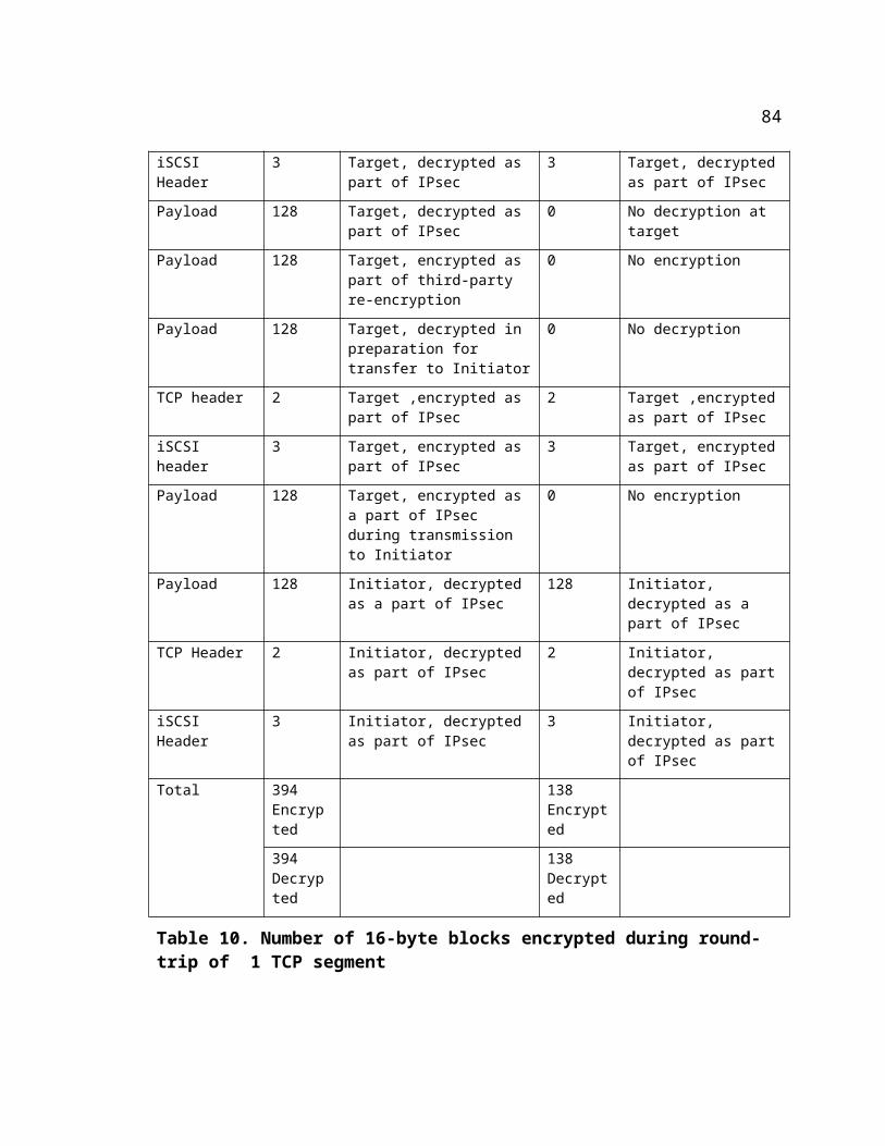
add-symbol-file /home/mandukur/iscsitarget-0.4.11/kernel/iscsi_trgt.ko 0x188d1000 \ -s .bss 0x188e0140 \ -s .data 0x188dfce0 \ -s .gnu.linkonce.this_module 0x188e0000 \ -s .rodata 0x188da2d8 \ -s .rodata.str1.1 0x188db124 \ -s .rodata.str1.32 0x188dbd00 \ -s .strtab 0x188de7b8 \ -s .symtab 0x188dc988 \ -s __param 0x188dc974
The text shown in bold above is the command to be entered at the gdb prompt.
93
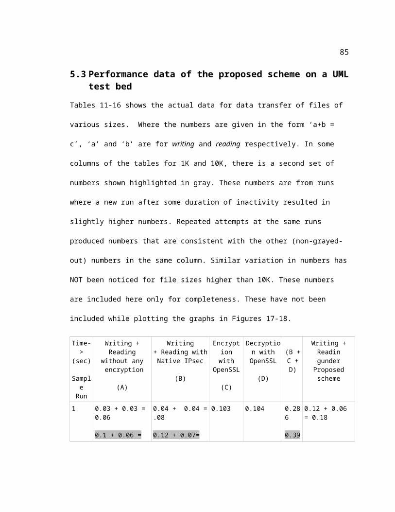
10.5 Appendix E : Compiling sg_dd and setting it up
As mentioned above, sg_dd is the utility used to write blocks of data to to the target, and read them back.
To build sgutils, install the following in the initiator uml (uml2) libtool-libs.1.5.8m4-1.4.1-14.i386.rpmautoconf-2.57-3.noarch.rpmautomake-1.7.8-1.noarch.rpmlibtool-1.5-8.i386.rpmsg3_utils-libs-1.19-1.1.i386.rpm (The following are dependencies for libpthread)
basesystem-8.0-2.noarch.rpmglibc-common-2.3.2-101.i386.rpm glibc-2.3.2-101.i386.rpm And then, build inside the sgutils source directory, using Makefile.asroot
make –f Makefile.asrootmake –f Makefile.asroot install
94
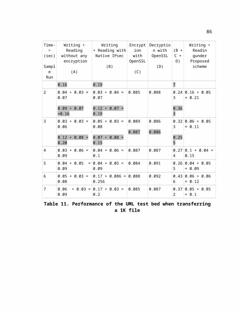
11 Appendix F: A typical run through the test bed
Given below are the list of steps for a typical ‘write’ and ‘read’ session between the initiator and
the target.
11.1 Step 1: Create the ‘disk’ on the target
(This command needs to be executed on the target)
On the target, make sure the file that is supposed to be presented as a disk to the initiator, does
indeed exist. The name of the file is obtained from the 'Lun' entry of /etc/ietd.conf on the iscsi
target. In the testbed, the entry is
Lun 0 Path =/tmp/target_file,Type=fileio
The Path can point to a real disk , as in /dev/sdc
If the file does not exist, create it using the 'dd' command. An example is
dd if=/dev/zero of=/tmp/target_file bs=1024 count=24576 conv=sync
11.2 Step 2: Start the iSCSI target software
(This command needs to be executed on the target)
/etc/init.d/iscsi-target start (The iscsi-target script is installed as a part of installing the iscsi-target)
95
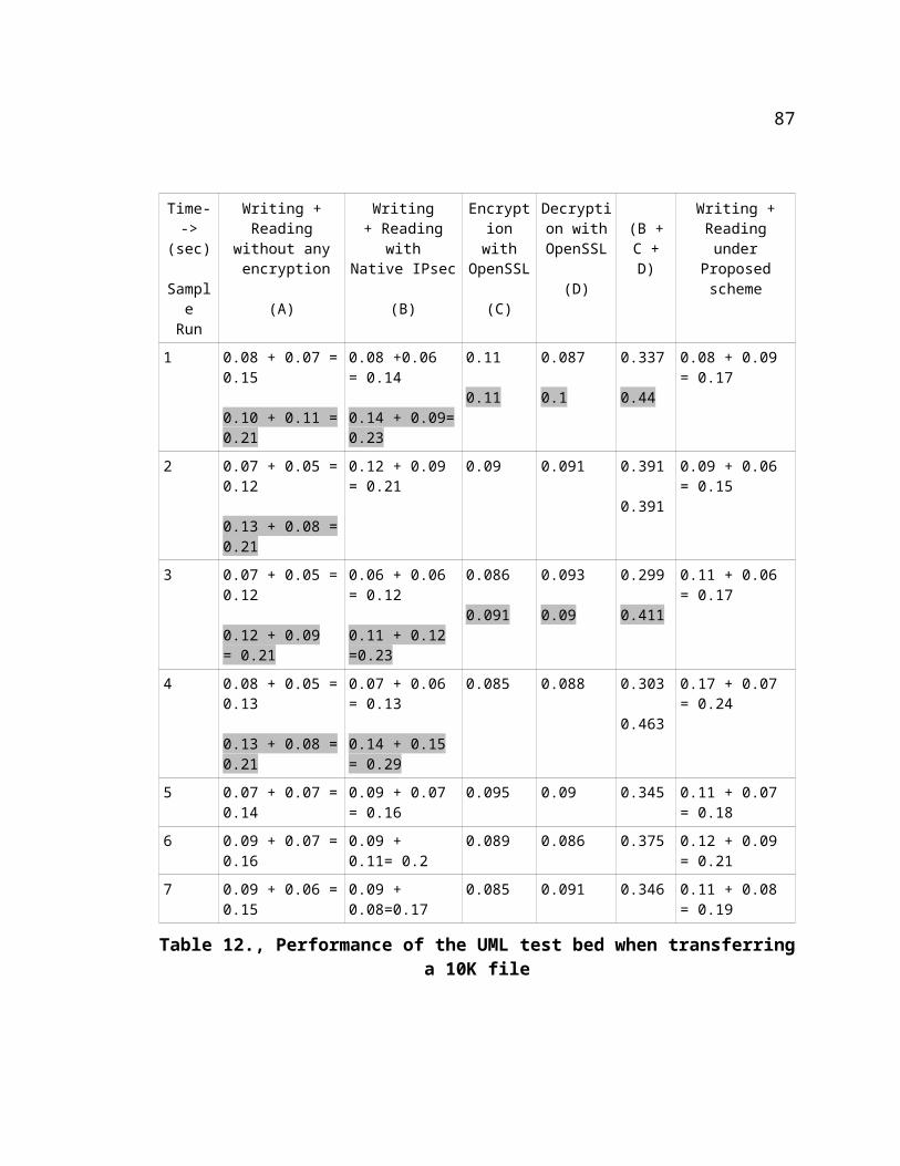
11.3 Step 3: Start the iSCSI Initiator daemon
(This command needs to be executed on the Initiator)
#!/bin/bash#cd /lib/modules/2.6.12.1-bs7y/kernel/drivers/scsimodprobe scsi_modmodprobe sd_modmodprobe sgmodprobe scsi_transport_iscsiiscsid -c /etc/iscsid.conf -f -d10&modprobe iscsi_tcp
11.4 Step 4 : Login to the target
(This command needs to be executed on the Initiator)
/root/open-iscsi/usr/iscsiadm -m discovery --type sendtargets --portal
The scsi node id will be printed here. A typical example looks like
[4dbdf2] 192.168.0.151:3260,1 iqn.2001-04.com.example:storage.disk2.sys1.xyz
/root/open-iscsi//usr/iscsiadm -m node --record 4dbdf2 –login
This outputs a lot of text that ends with
..
..iscsid: scanning host0 using /sys/class/scsi_host/host0/scan Vendor: IET Model: VIRTUAL-DISK Rev: 0 Type: Direct-Access ANSI SCSI revision: 04SCSI device sda: 49152 512-byte hdwr sectors (25 MB)SCSI device sda: drive cache: write backSCSI device sda: 49152 512-byte hdwr sectors (25 MB)SCSI device sda: drive cache: write back
96
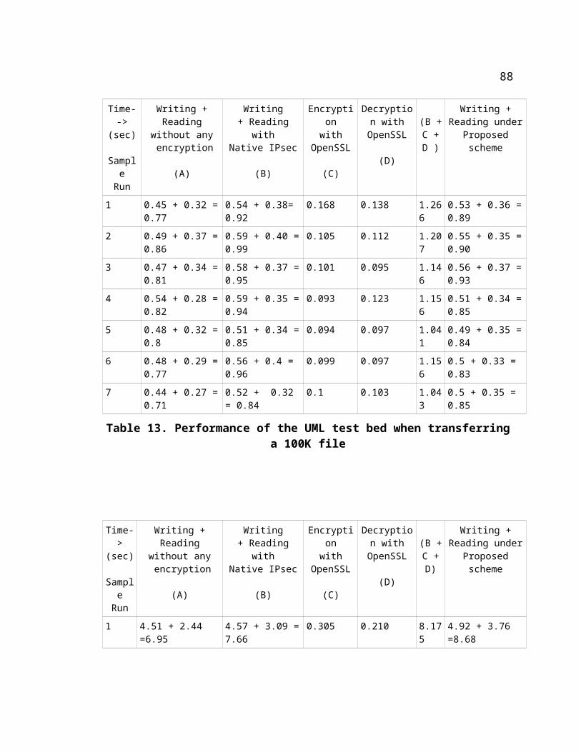
Attached scsi disk sda at scsi0, channel 0, id 0, lun 0Attached scsi generic sg0 at scsi0, channel 0, id 0, lun 0, type 0iscsid: connection0:0 is operational nowiscsid: thread 4026a444 removed from actor_list
At the current stage, the implementation of the scheme is limited to
handling file sizes that are exact multiples of 1024. That is because
the SCSI layer seems to send out scatter-gather buffer pointers
referring to full block size, to the iSCSI layer. The exact nature of
communication between the SCSI layer and iSCSI layer is not yet
completely understood by the author of this thesis.
The command to write a file to a target looks like
sg_dd if=test_file_100MB.txt of=/dev/scsi/host0/bus0/target0/lun0/disc bs=1024 bpt=1 odir=1 count=102400 skip=0 seek=0
11.5 Step 5 : Verifying that data is scrambled on the target
(This command needs to be executed on the target)
In this step we read the data from the target. The command
dd if=/tmp/target_file of=data_read_file bs=1024 count=same_value_as_from_the_above_sgdd_command
retrieves the data written to the target disk into a local file called ‘data_read_file’. The contents of
the file (looked at with ‘vi’ or ‘cat’ ) look scrambled.
11.6 Step 6: Read data from the Initiator
(This command needs to be executed on the Initiator)
The command run below is only slightly different from the earlier command run to ‘write’ the
data. Note that the ‘of’ in the earlier step now becomes the ‘if’. There is a new ‘of’ to store the
97
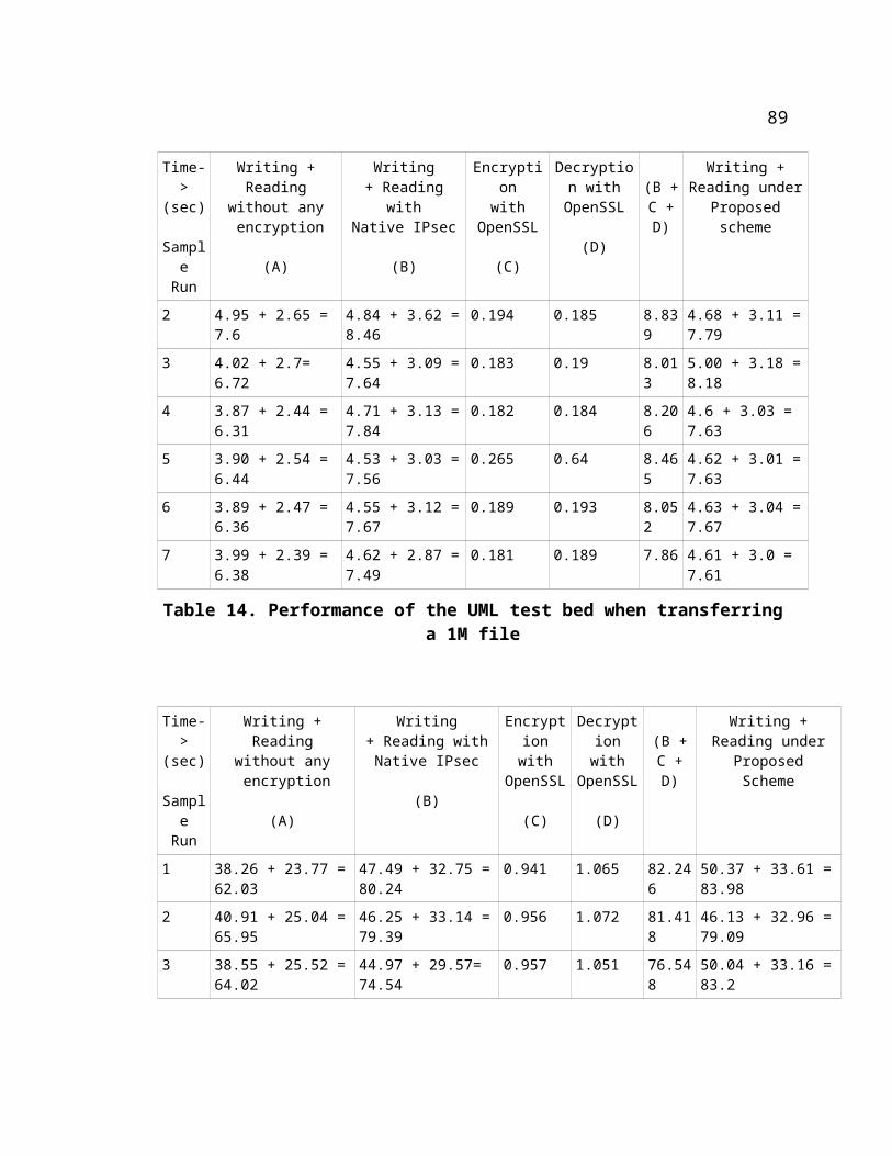
retrieved contents.
sg_dd if=/dev/scsi/host0/bus0/target0/lun0/disc of=retrieved_data bs=1024 bpt=1 odir=1 count=102400 skip=0 seek=0
11.7 Step 7: Verifying the correctness of the data
(This command needs to be executed on the Initiator)
Run the command ‘cksum’ on both the input and output files. i.e.
‘cksum test_file_100MB.txt’ and ‘cksum retrieved_data’
should display identical numbers.
Note : Every time a new login happens from the Initiator to the target, the host id of the target
according to the initiator, changes, So, in the above commands to ‘write’ and ‘read’, it could be
host0 or host1 or host 2 .
98