efficient duct - semcohvac.com duct system... · efficient duct system design: make semco spiral...
TRANSCRIPT
DUCT
EFFICIENT
ACOUSTICAL EFFICIENT DUCTSYSTEM DESIGN
WHY SPIRAL DUCT SHOULD BEYOUR FIRST CHOICE
2
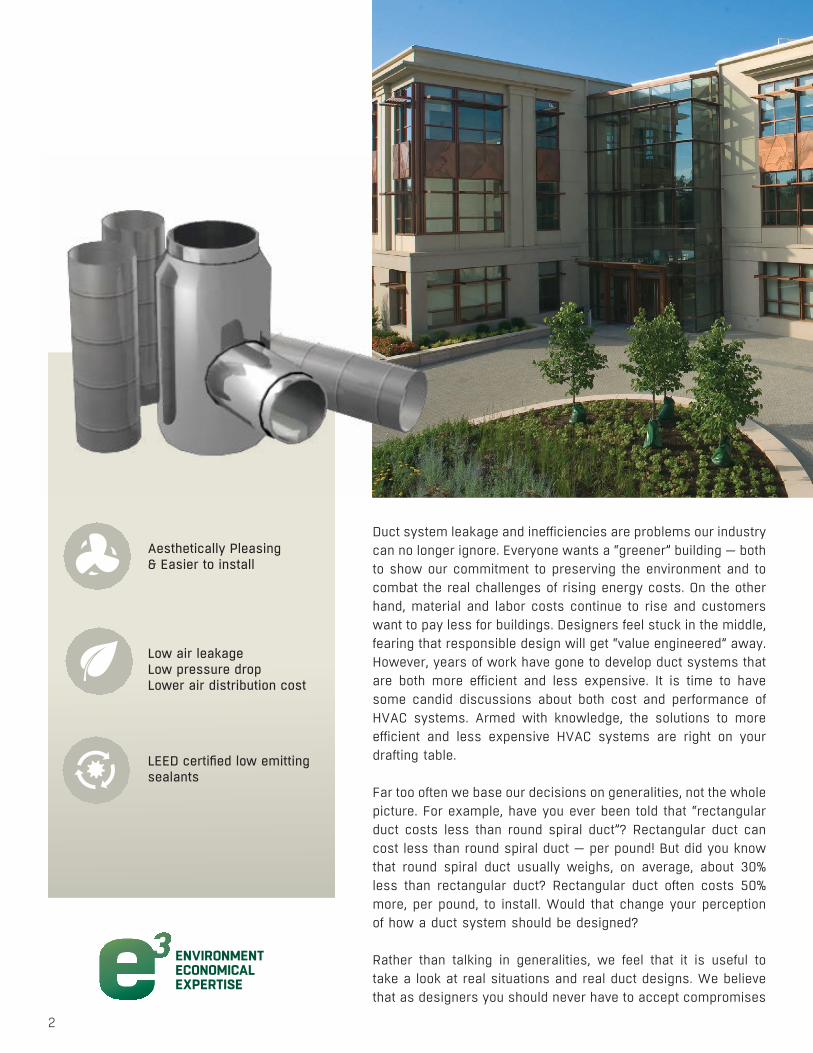
LEED certified low emitting sealants
Low air leakageLow pressure dropLower air distribution cost
Aesthetically Pleasing& Easier to install
ENVIRONMENTECONOMICALEXPERTISE
INTELLIGENTINNOVATIVEINVESTMENT
ENVIRONMENTECONOMICALEXPERTISE
INTELLIGENTINNOVATIVEINVESTMENT
Duct system leakage and inefficiencies are problems our industry can no longer ignore. Everyone wants a “greener” building — both to show our commitment to preserving the environment and to combat the real challenges of rising energy costs. On the other hand, material and labor costs continue to rise and customers want to pay less for buildings. Designers feel stuck in the middle, fearing that responsible design will get “value engineered” away. However, years of work have gone to develop duct systems that are both more efficient and less expensive. It is time to have some candid discussions about both cost and performance of HVAC systems. Armed with knowledge, the solutions to more efficient and less expensive HVAC systems are right on your drafting table.
Far too often we base our decisions on generalities, not the whole picture. For example, have you ever been told that “rectangular duct costs less than round spiral duct”? Rectangular duct can cost less than round spiral duct — per pound! But did you know that round spiral duct usually weighs, on average, about 30% less than rectangular duct? Rectangular duct often costs 50% more, per pound, to install. Would that change your perception of how a duct system should be designed?
Rather than talking in generalities, we feel that it is useful to take a look at real situations and real duct designs. We believe that as designers you should never have to accept compromises

SEMCO’s exposed spiral round and oval duct is easy to install, looks great, saves time and reduces costs.
3
DUCT SYSTEM DESIGN
MATERIALS AVAILABLE• Aluminum• Galvanized steel• Stainless steel
SIZES AVAILABLE• Round spiral duct up to 120” in diameter • Round longitudinal seam duct to 100+” in diameter• Oval spiral duct in over 350 sizes with minors 4”-32”• Oval longitudinal seam duct in any size
OPTIONS AND ACCESSORIES• Air diffusing perforated spiral duct • Available in single & dual wall round and oval• AVRON46® antimicrobial coating• Diffus-A-Plate duct diffusers• Largest variety of proprietary joint connectors
available• Manifolded duct• Rectangular taps• Velocity® self-sealing joint connection
EFFICIENT DUCT SYSTEM DESIGN: MAKE SEMCO SPIRAL DUCT YOUR FIRST CHOICE
in performance. Armed with knowledge from real job examples, you can make informed decisions on product selection and scope resulting in more efficient, less expensive duct systems.
In comparing duct performance, two elements should be equal in the related designs. The first is dynamic performance. For comparison, the duct systems should have the same pressure drop from the fan to the grille. Most designers use either the equal-friction or static-regain design methodologies when sizing a duct system. We have chosen to keep it simple with an equal-friction comparison. Sizing choices can be verified using a “ductulator” type device. The second element is structural performance. The criteria for duct construction standards, including the widely used SMACNA HVAC Duct Construction Standards, is maintaining a maximum allowable duct deflection at a design pressure. All comparisons of cost and performance in this example are based on a design pressure of 2.0” WG from the fan to mixing boxes and 0.5” WG from the mixing box to the grille.
4
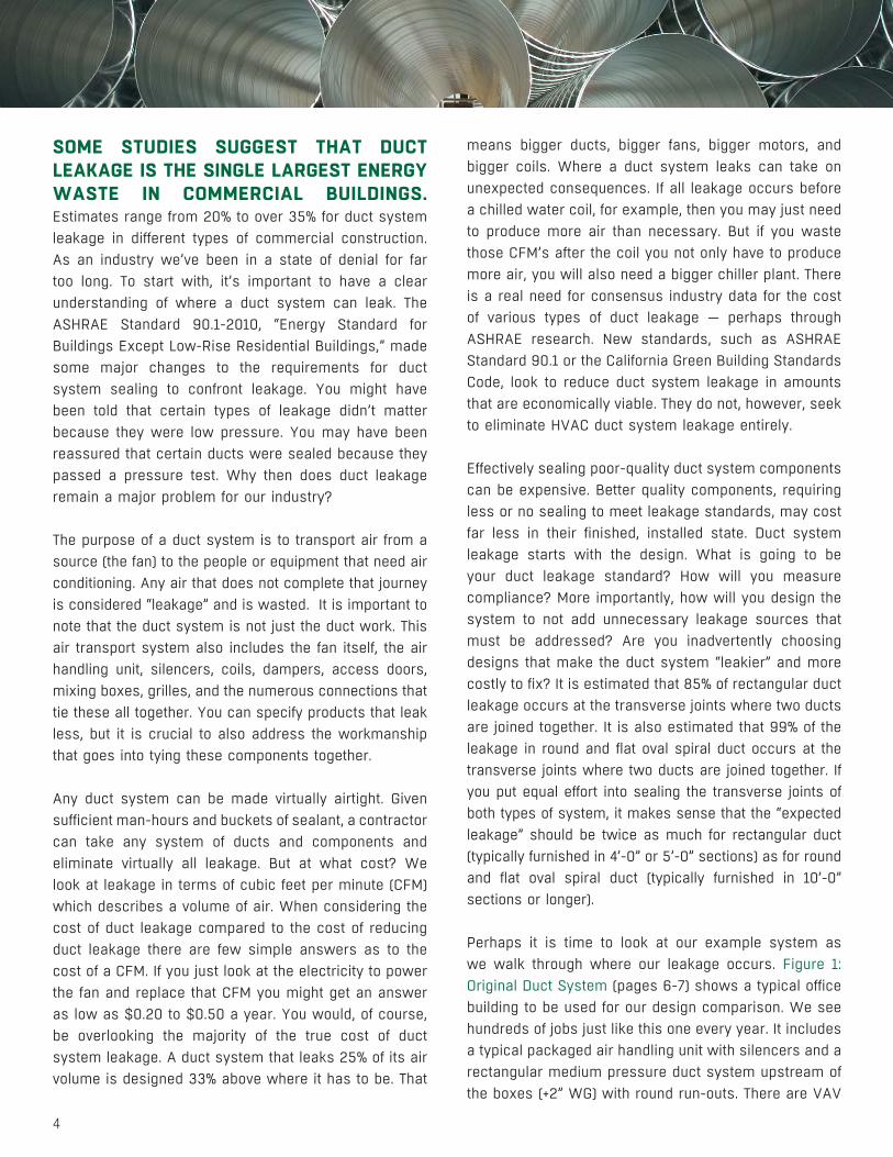
SOME STUDIES SUGGEST THAT DUCT LEAKAGE IS THE SINGLE LARGEST ENERGY WASTE IN COMMERCIAL BUILDINGS. Estimates range from 20% to over 35% for duct system leakage in different types of commercial construction. As an industry we’ve been in a state of denial for far too long. To start with, it’s important to have a clear understanding of where a duct system can leak. The ASHRAE Standard 90.1-2010, “Energy Standard for Buildings Except Low-Rise Residential Buildings,” made some major changes to the requirements for duct system sealing to confront leakage. You might have been told that certain types of leakage didn’t matter because they were low pressure. You may have been reassured that certain ducts were sealed because they passed a pressure test. Why then does duct leakage remain a major problem for our industry?
The purpose of a duct system is to transport air from a source (the fan) to the people or equipment that need air conditioning. Any air that does not complete that journey is considered “leakage” and is wasted. It is important to note that the duct system is not just the duct work. This air transport system also includes the fan itself, the air handling unit, silencers, coils, dampers, access doors, mixing boxes, grilles, and the numerous connections that tie these all together. You can specify products that leak less, but it is crucial to also address the workmanship that goes into tying these components together.
Any duct system can be made virtually airtight. Given sufficient man-hours and buckets of sealant, a contractor can take any system of ducts and components and eliminate virtually all leakage. But at what cost? We look at leakage in terms of cubic feet per minute (CFM) which describes a volume of air. When considering the cost of duct leakage compared to the cost of reducing duct leakage there are few simple answers as to the cost of a CFM. If you just look at the electricity to power the fan and replace that CFM you might get an answer as low as $0.20 to $0.50 a year. You would, of course, be overlooking the majority of the true cost of duct system leakage. A duct system that leaks 25% of its air volume is designed 33% above where it has to be. That
means bigger ducts, bigger fans, bigger motors, and bigger coils. Where a duct system leaks can take on unexpected consequences. If all leakage occurs before a chilled water coil, for example, then you may just need to produce more air than necessary. But if you waste those CFM’s after the coil you not only have to produce more air, you will also need a bigger chiller plant. There is a real need for consensus industry data for the cost of various types of duct leakage — perhaps through ASHRAE research. New standards, such as ASHRAE Standard 90.1 or the California Green Building Standards Code, look to reduce duct system leakage in amounts that are economically viable. They do not, however, seek to eliminate HVAC duct system leakage entirely.
Effectively sealing poor-quality duct system components can be expensive. Better quality components, requiring less or no sealing to meet leakage standards, may cost far less in their finished, installed state. Duct system leakage starts with the design. What is going to be your duct leakage standard? How will you measure compliance? More importantly, how will you design the system to not add unnecessary leakage sources that must be addressed? Are you inadvertently choosing designs that make the duct system “leakier” and more costly to fix? It is estimated that 85% of rectangular duct leakage occurs at the transverse joints where two ducts are joined together. It is also estimated that 99% of the leakage in round and flat oval spiral duct occurs at the transverse joints where two ducts are joined together. If you put equal effort into sealing the transverse joints of both types of system, it makes sense that the “expected leakage” should be twice as much for rectangular duct (typically furnished in 4’-0” or 5’-0” sections) as for round and flat oval spiral duct (typically furnished in 10’-0” sections or longer).
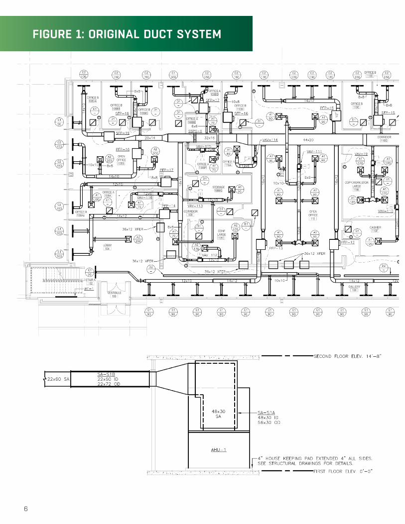
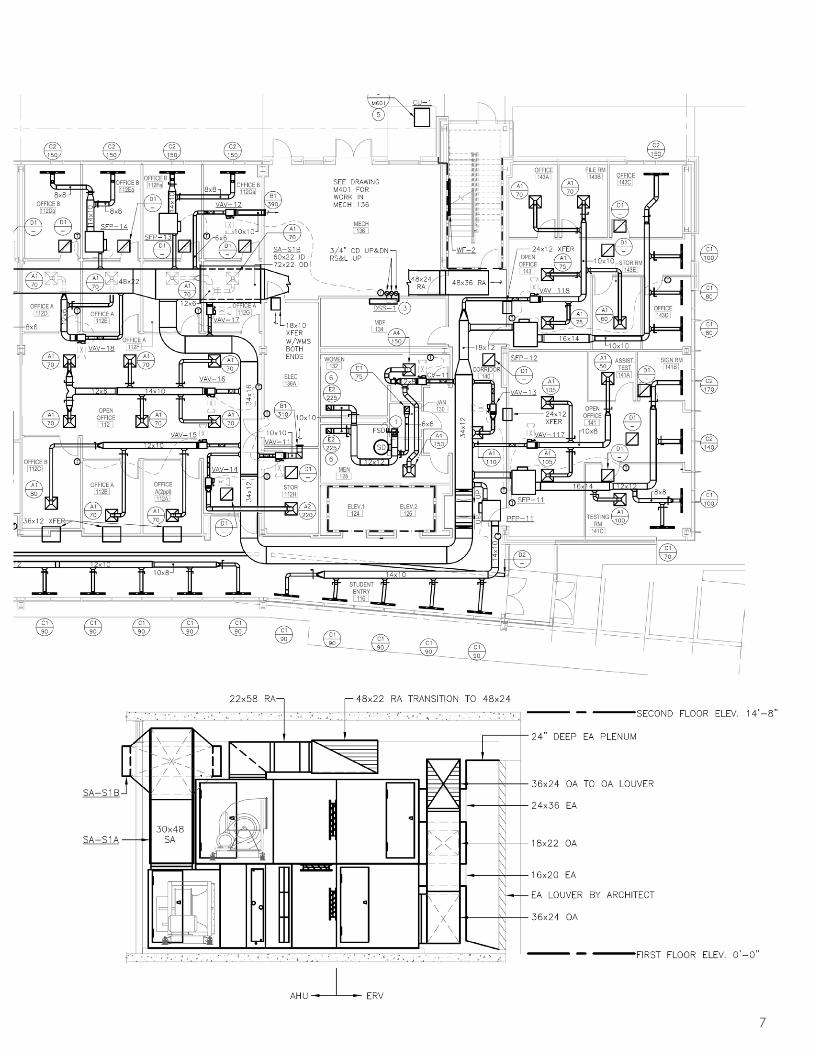
Perhaps it is time to look at our example system as we walk through where our leakage occurs. Figure 1: Original Duct System (pages 6-7) shows a typical office building to be used for our design comparison. We see hundreds of jobs just like this one every year. It includes a typical packaged air handling unit with silencers and a rectangular medium pressure duct system upstream of the boxes (+2” WG) with round run-outs. There are VAV
5
DUCT SYSTEM DESIGN
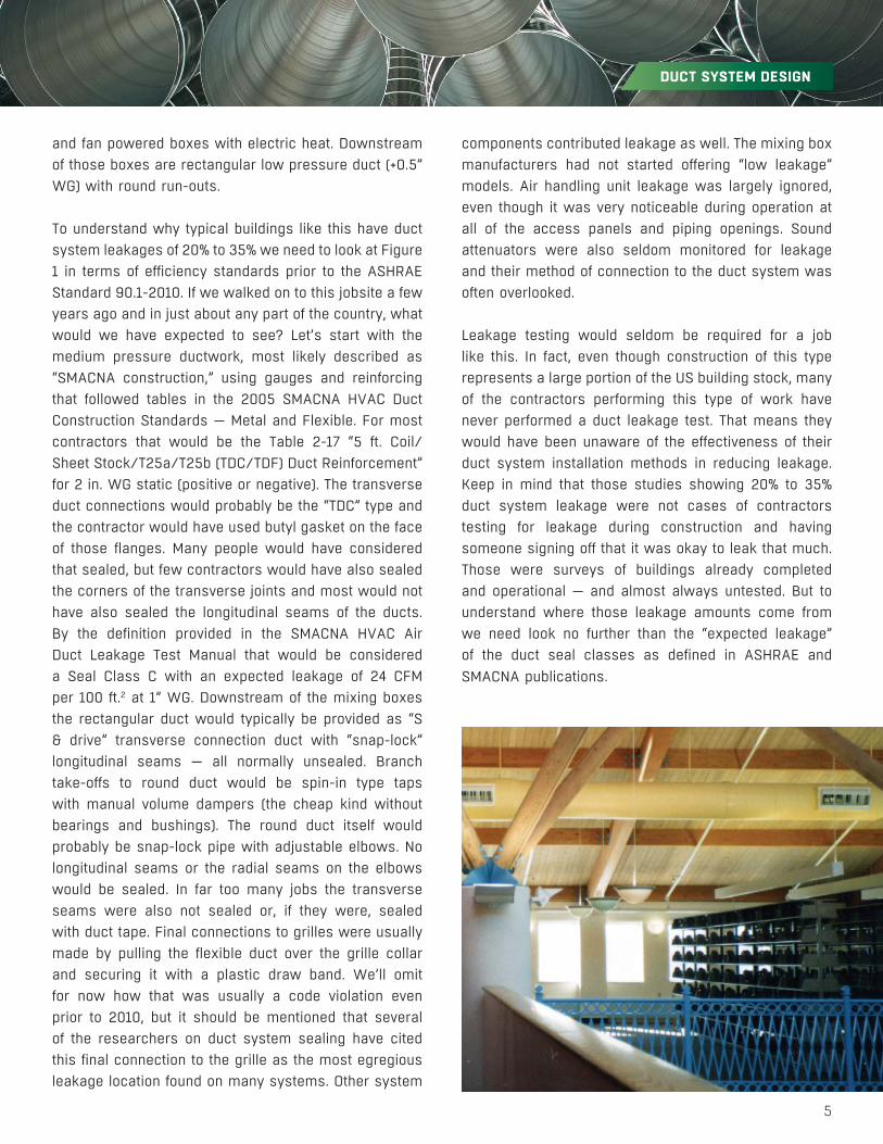
and fan powered boxes with electric heat. Downstream of those boxes are rectangular low pressure duct (+0.5” WG) with round run-outs. To understand why typical buildings like this have duct system leakages of 20% to 35% we need to look at Figure 1 in terms of efficiency standards prior to the ASHRAE Standard 90.1-2010. If we walked on to this jobsite a few years ago and in just about any part of the country, what would we have expected to see? Let’s start with the medium pressure ductwork, most likely described as “SMACNA construction,” using gauges and reinforcing that followed tables in the 2005 SMACNA HVAC Duct Construction Standards — Metal and Flexible. For most contractors that would be the Table 2-17 “5 ft. Coil/Sheet Stock/T25a/T25b (TDC/TDF) Duct Reinforcement” for 2 in. WG static (positive or negative). The transverse duct connections would probably be the “TDC” type and the contractor would have used butyl gasket on the face of those flanges. Many people would have considered that sealed, but few contractors would have also sealed the corners of the transverse joints and most would not have also sealed the longitudinal seams of the ducts. By the definition provided in the SMACNA HVAC Air Duct Leakage Test Manual that would be considered a Seal Class C with an expected leakage of 24 CFM per 100 ft.2 at 1” WG. Downstream of the mixing boxes the rectangular duct would typically be provided as “S & drive” transverse connection duct with “snap-lock” longitudinal seams — all normally unsealed. Branch take-offs to round duct would be spin-in type taps with manual volume dampers (the cheap kind without bearings and bushings). The round duct itself would probably be snap-lock pipe with adjustable elbows. No longitudinal seams or the radial seams on the elbows would be sealed. In far too many jobs the transverse seams were also not sealed or, if they were, sealed with duct tape. Final connections to grilles were usually made by pulling the flexible duct over the grille collar and securing it with a plastic draw band. We’ll omit for now how that was usually a code violation even prior to 2010, but it should be mentioned that several of the researchers on duct system sealing have cited this final connection to the grille as the most egregious leakage location found on many systems. Other system
components contributed leakage as well. The mixing box manufacturers had not started offering “low leakage” models. Air handling unit leakage was largely ignored, even though it was very noticeable during operation at all of the access panels and piping openings. Sound attenuators were also seldom monitored for leakage and their method of connection to the duct system was often overlooked.
Leakage testing would seldom be required for a job like this. In fact, even though construction of this type represents a large portion of the US building stock, many of the contractors performing this type of work have never performed a duct leakage test. That means they would have been unaware of the effectiveness of their duct system installation methods in reducing leakage. Keep in mind that those studies showing 20% to 35% duct system leakage were not cases of contractors testing for leakage during construction and having someone signing off that it was okay to leak that much. Those were surveys of buildings already completed and operational — and almost always untested. But to understand where those leakage amounts come from we need look no further than the “expected leakage” of the duct seal classes as defined in ASHRAE and SMACNA publications.
6
FIGURE 1: ORIGINAL DUCT SYSTEM
7

8
ORIGINAL SYSTEM — 11,730 CFM
MEDIUM PRESSURE DUCT SYSTEMRECTANGULAR DUCT
• 386 linear feet of duct• 2,797 ft.2 of duct surface• 107 transverse joints• 771 linear feet of transverse seams• 772 linear feet of longitudinal seam• 7 rectangular taps (37 linear feet of perimeter)
At Seal Class C construction (transverse joints only) and 2” WG, expected leakage is 37.7 CFM per 100 ft.2 of duct surface = 1,054 CFM of leakage — 8.99% of fan flow
ROUND DUCT• 179 lineal feet of duct• 311 ft.2 of duct surface• 149 transverse joints• 254 lineal feet of transverse seams• 27 taps (62 lineal feet of tap perimeter)
At Seal Class C construction (transverse joints only) and 2” WG, expected leakage is 18.8 CFM per 100 ft.2 of duct surface = 58 CFM of leakage — 0.5% of fan flow
LOW PRESSURE DUCT SYSTEM • 2,720 ft.2 of rectangular duct• 1,388 ft.2 of round duct• 250 rectangular transverse connections (with
869 linear feet of seam)• 1,494 linear feet of rectangular longitudinal
seam• 598 round transverse connections (with
1,023 linear feet of seam)• 624 linear feet of round snap-lock duct side
seam• 156 adjustable elbows (with 801 lineal feet of
radial seam)• 66 taps• 103 volume dampers
Unsealed (expected leakage class 48) and 0.5” WG, expected leakage is 30.6 CFM per 100 ft.2 of duct surface = 1,257 CFM of leakage — 10.7% of fan flow
9
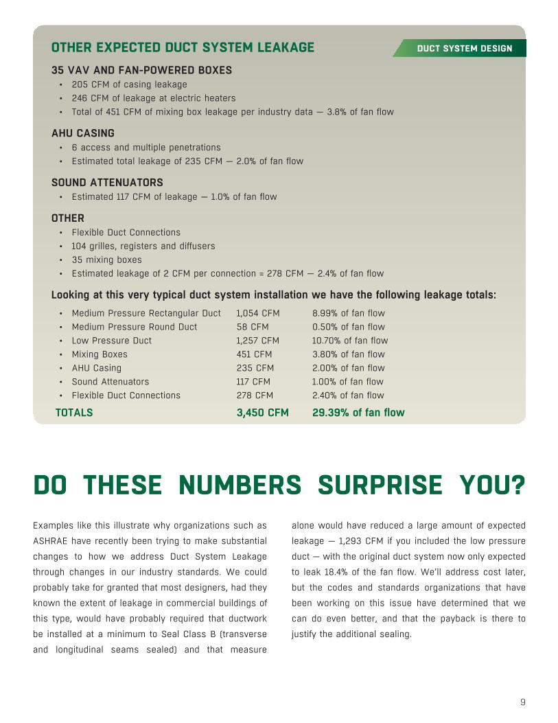
DUCT SYSTEM DESIGNOTHER EXPECTED DUCT SYSTEM LEAKAGE 35 VAV AND FAN-POWERED BOXES
• 205 CFM of casing leakage• 246 CFM of leakage at electric heaters• Total of 451 CFM of mixing box leakage per industry data — 3.8% of fan flow
AHU CASING • 6 access and multiple penetrations• Estimated total leakage of 235 CFM — 2.0% of fan flow
SOUND ATTENUATORS• Estimated 117 CFM of leakage — 1.0% of fan flow
OTHER• Flexible Duct Connections• 104 grilles, registers and diffusers• 35 mixing boxes• Estimated leakage of 2 CFM per connection = 278 CFM — 2.4% of fan flow
Looking at this very typical duct system installation we have the following leakage totals:• Medium Pressure Rectangular Duct 1,054 CFM 8.99% of fan flow• Medium Pressure Round Duct 58 CFM 0.50% of fan flow• Low Pressure Duct 1,257 CFM 10.70% of fan flow• Mixing Boxes 451 CFM 3.80% of fan flow• AHU Casing 235 CFM 2.00% of fan flow• Sound Attenuators 117 CFM 1.00% of fan flow• Flexible Duct Connections 278 CFM 2.40% of fan flow
TOTALS 3,450 CFM 29.39% of fan flow
Examples like this illustrate why organizations such as
ASHRAE have recently been trying to make substantial
changes to how we address Duct System Leakage
through changes in our industry standards. We could
probably take for granted that most designers, had they
known the extent of leakage in commercial buildings of
this type, would have probably required that ductwork
be installed at a minimum to Seal Class B (transverse
and longitudinal seams sealed) and that measure
alone would have reduced a large amount of expected
leakage — 1,293 CFM if you included the low pressure
duct — with the original duct system now only expected
to leak 18.4% of the fan flow. We’ll address cost later,
but the codes and standards organizations that have
been working on this issue have determined that we
can do even better, and that the payback is there to
justify the additional sealing.
DO THESE NUMBERS SURPRISE YOU?
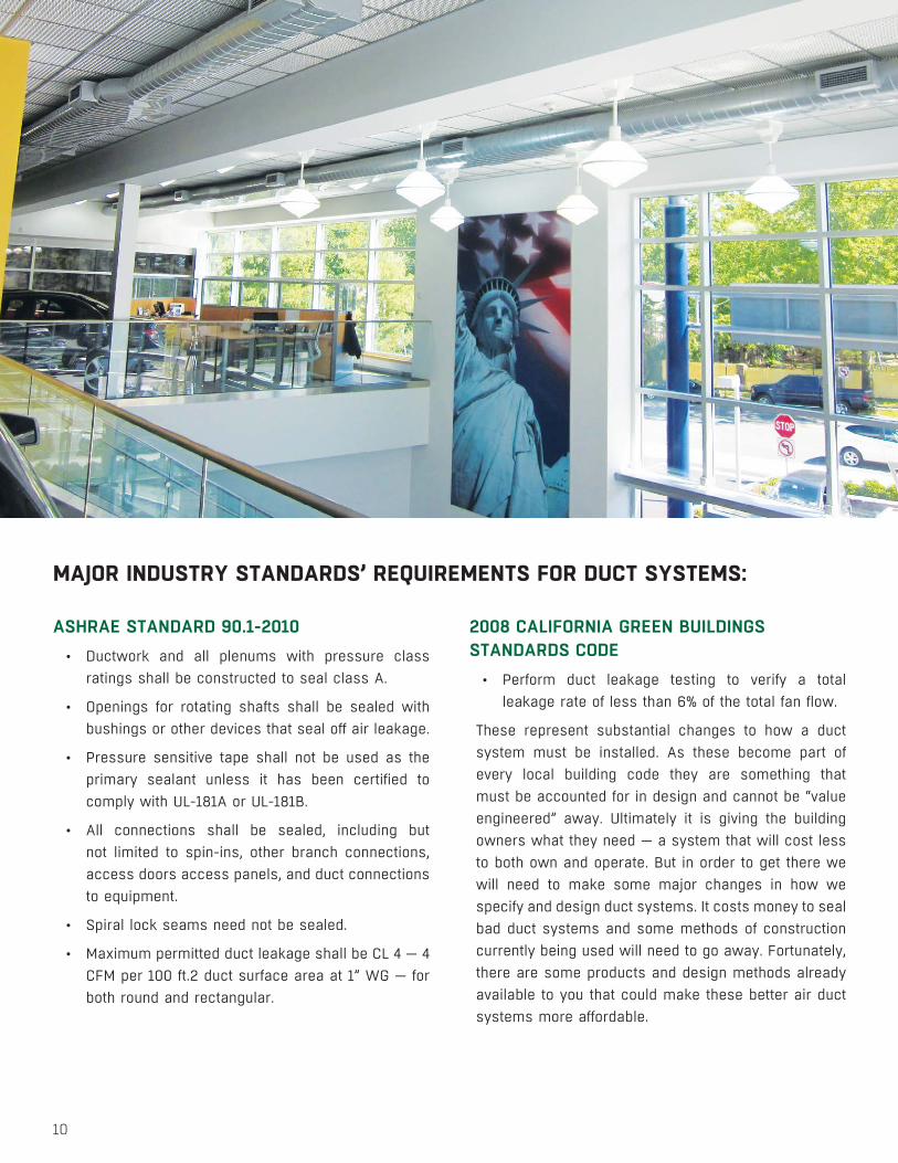
ASHRAE STANDARD 90.1-2010• Ductwork and all plenums with pressure class
ratings shall be constructed to seal class A.
• Openings for rotating shafts shall be sealed with bushings or other devices that seal off air leakage.
• Pressure sensitive tape shall not be used as the primary sealant unless it has been certified to comply with UL-181A or UL-181B.
• All connections shall be sealed, including but not limited to spin-ins, other branch connections, access doors access panels, and duct connections to equipment.
• Spiral lock seams need not be sealed.
• Maximum permitted duct leakage shall be CL 4 — 4 CFM per 100 ft.2 duct surface area at 1” WG — for both round and rectangular.
MAJOR INDUSTRY STANDARDS’ REQUIREMENTS FOR DUCT SYSTEMS:
2008 CALIFORNIA GREEN BUILDINGS STANDARDS CODE
• Perform duct leakage testing to verify a total leakage rate of less than 6% of the total fan flow.
These represent substantial changes to how a duct system must be installed. As these become part of every local building code they are something that must be accounted for in design and cannot be “value engineered” away. Ultimately it is giving the building owners what they need — a system that will cost less to both own and operate. But in order to get there we will need to make some major changes in how we specify and design duct systems. It costs money to seal bad duct systems and some methods of construction currently being used will need to go away. Fortunately, there are some products and design methods already available to you that could make these better air duct systems more affordable.
10
11
Contractors know what duct systems cost, including the cost to take current designs and seal them to new standards. Expect to hear that sealing everything to a Seal Class A, or 6% total system leakage, is going to cost a lot of money. That could be true — if you are just trying to work with the products, methods and designs that were leaking so badly in the first place! What you won’t be able to find out, unless you start adjusting designs and asking about comparison prices, is how to make adjustments for a more efficient design at an equal or lower cost. That’s where we are going to help out.
As a major duct manufacturer, SEMCO has a staff with hundreds of years of combined duct building and pricing experience, as well as people with experience in the mechanical and sheet metal contracting fields. Though we don’t bid jobs as an installing contractor, we have people that know how to do it. When we give material prices they will be “street prices” — the cost a local contractor would normally expect to pay — rather than our own internal cost to produce. For labor estimates we use a median cost of $60 per man-hour (inclusive of benefits) and estimating algorithms from the National Mechanical Estimator by Victor Ottaviano (1990).
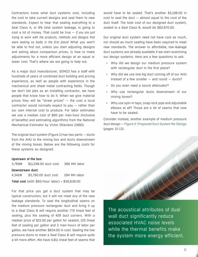
The original duct system (Figure 1) has two parts — ducts from the AHU to the mixing box and ducts downstream of the mixing boxes. Below are the following costs for these systems as designed:
Upstream of the box: 5,769# $11,248.00 duct cost 366 MH labor
Downstream duct:4,342# $5,790.00 duct cost 294 MH labor
Total cost (with $60/hour labor) = $56,638.00
For that price you get a duct system that may be typical construction, but it will not meet any of the new leakage standards. To seal the longitudinal seams on the medium pressure rectangular duct and bring it up to a Seal Class B will require another 772 lineal feet of sealing, plus the sealing of 428 duct corners. With a median price of $15.00 per gallon for sealant, 125 lineal feet of sealing per gallon and 2 man-hours of labor per gallon, we have another $834.00 in cost. Sealing the low pressure ducts to meet a Seal Class B will require quite a bit more effort. We have 4,811 lineal feet of seams that
would have to be sealed. That’s another $5,198.00 in cost to seal the duct — almost equal to the cost of the duct itself. The total cost of our designed duct system, sealed to a Seal Class B, would be $62,670.00.
Our original duct system need not have cost as much, nor should as much sealing have been required to meet new standards. The answer to affordable, low-leakage duct systems are already available if we start examining our design systems. Here are a few questions to ask:
• Why did we design our medium pressure system with rectangular duct in the first place?
• Why did we use one big duct coming off of our AHU instead of a few smaller — and round — ducts?
• Do you even need a sound attenuator?
• Why use rectangular ducts downstream of our mixing boxes?
• Why use spin-in taps, snap-lock pipe and adjustable elbows at all? Those are a lot of seams that now have to be sealed.
Consider instead, another example of medium pressure duct design — Figure 2: Proposed Duct System Re-Design (pages 12-13).
The acoustical attributes of dual wall duct significantly reduce associated HVAC noise levels while the thermal benefits make the system more energy efficient.
12
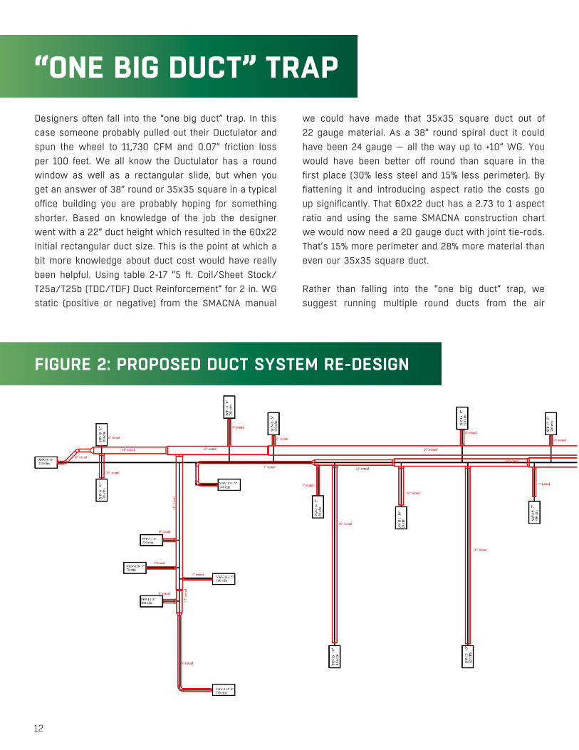
“ONE BIG DUCT” TRAPDesigners often fall into the “one big duct” trap. In this case someone probably pulled out their Ductulator and spun the wheel to 11,730 CFM and 0.07” friction loss per 100 feet. We all know the Ductulator has a round window as well as a rectangular slide, but when you get an answer of 38” round or 35x35 square in a typical office building you are probably hoping for something shorter. Based on knowledge of the job the designer went with a 22” duct height which resulted in the 60x22 initial rectangular duct size. This is the point at which a bit more knowledge about duct cost would have really been helpful. Using table 2-17 “5 ft. Coil/Sheet Stock/T25a/T25b (TDC/TDF) Duct Reinforcement” for 2 in. WG static (positive or negative) from the SMACNA manual
we could have made that 35x35 square duct out of 22 gauge material. As a 38” round spiral duct it could have been 24 gauge — all the way up to +10” WG. You would have been better off round than square in the first place (30% less steel and 15% less perimeter). By flattening it and introducing aspect ratio the costs go up significantly. That 60x22 duct has a 2.73 to 1 aspect ratio and using the same SMACNA construction chart we would now need a 20 gauge duct with joint tie-rods. That’s 15% more perimeter and 28% more material than even our 35x35 square duct.
Rather than falling into the “one big duct” trap, we suggest running multiple round ducts from the air
FIGURE 2: PROPOSED DUCT SYSTEM RE-DESIGN
13
DUCT SYSTEM DESIGN
SO, WHAT DOES THIS NEW, BETTER SYSTEM COST?
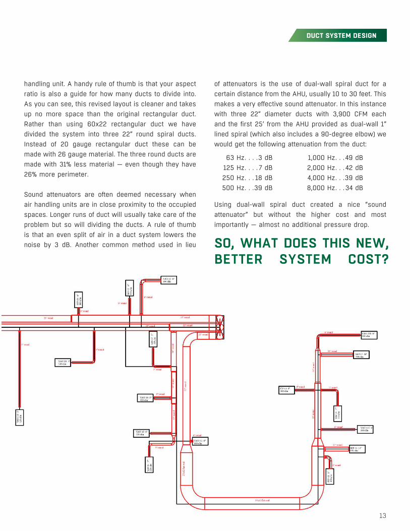
handling unit. A handy rule of thumb is that your aspect ratio is also a guide for how many ducts to divide into. As you can see, this revised layout is cleaner and takes up no more space than the original rectangular duct. Rather than using 60x22 rectangular duct we have divided the system into three 22” round spiral ducts. Instead of 20 gauge rectangular duct these can be made with 26 gauge material. The three round ducts are made with 31% less material — even though they have 26% more perimeter.
Sound attenuators are often deemed necessary when air handling units are in close proximity to the occupied spaces. Longer runs of duct will usually take care of the problem but so will dividing the ducts. A rule of thumb is that an even split of air in a duct system lowers the noise by 3 dB. Another common method used in lieu
of attenuators is the use of dual-wall spiral duct for a certain distance from the AHU, usually 10 to 30 feet. This makes a very effective sound attenuator. In this instance with three 22” diameter ducts with 3,900 CFM each and the first 25’ from the AHU provided as dual-wall 1” lined spiral (which also includes a 90-degree elbow) we would get the following attenuation from the duct:
Using dual-wall spiral duct created a nice “sound attenuator” but without the higher cost and most importantly — almost no additional pressure drop.
63 Hz . . . .3 dB 125 Hz . . . . 7 dB 250 Hz . . . 18 dB 500 Hz . . .39 dB
1,000 Hz . . .49 dB 2,000 Hz . . . 42 dB 4,000 Hz . . .39 dB 8,000 Hz . . .34 dB
14
COST COMPARISONORIGINAL VS NEW DUCT SYSTEM
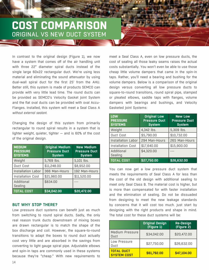
In contrast to the original design (Figure 1), we now have a system that comes off of the air handling unit with three 22” diameter spiral ducts instead of the single large 60x22 rectangular duct. We’re using less material and eliminating the sound attenuator by using dual-wall spiral duct for the first 25’ from the AHU. Better still, this system is made of products SEMCO can provide with very little lead time. The round ducts can be provided as SEMCO’s Velocity Gasket Joint System and the flat oval ducts can be provided with oval Accu-Flanges. Installed, this system will meet a Seal Class A without external sealant.
Changing the design of this system from primarily rectangular to round spiral results in a system that is lighter weight, quieter, tighter — and is 60% of the cost of the original design.
BUT WHY STOP THERE? Low pressure duct systems can benefit just as much from switching to round spiral ducts. Sadly, the only real reason trunk ducts downstream of mixing boxes are drawn rectangular is to match the shape of the box discharge and coil. However, the square-to-round transitions to adapt the boxes to round duct actually cost very little and are absorbed in the savings from converting to light gauge spiral pipe. Adjustable elbows and spin-in taps are commonly used in these systems because they’re “cheap.” With new requirements to
meet a Seal Class A, even on low pressure ducts, the cost of sealing all those leaky seams raises the actual costs substantially. You won’t even be able to use those cheap little volume dampers that came in the spin-in taps. Rather, you’ll need a bearing and bushing for the volume dampers. Below is a comparison of the original design versus converting all low pressure ducts to square-to-round transitions, round spiral pipe, stamped or pleated elbows, saddle taps with flanges, volume dampers with bearings and bushings, and Velocity Gasketed Joint Systems:
You can now get a low pressure duct system that meets the requirements of Seal Class A for less than the cost of the old design with additional sealing to meet only Seal Class B. The material cost is higher, but is more than compensated for with faster installation and the elimination of sealing. Do not be dissuaded from designing to meet the new leakage standards by concerns that it will cost too much. Just start by designing with the right products and shape in mind. The total cost for these duct systems will be:
MEDIUM PRESSURE SYSTEMS
Original Medium Pressure Duct
System
New Medium Pressure Duct
SystemWeight 5,769 lbs. 5,101 lbs.Duct Cost $11,248.00 $8,952.00 Installation Labor 366 Man-Hours 192 Man-HoursInstallation Cost $21,960.00 $11,520.00 Additional Sealing
$834.00 ---
TOTAL COST $34,042.00 $20,472.00
LOWPRESSURESYSTEMS
Original Low Pressure Duct
System
New Low Pressure Duct
SystemWeight 4,342 lbs. 5,309 lbs.Duct Cost $5,790.00 $10,732.00 Installation Labor 294 Man-Hours 265 Man-HoursInstallation Cost $17,640.00 $15,900.00 Additional Sealing
$4,320.00 ---
TOTAL COST $27,750.00 $26,632.00
Original Design (Figure 1)
Re-Design(Figure 2)
Medium Pressure Duct $34,042.00 $20,472.00
Low Pressure Duct $27,750.00 $26,632.00
TOTAL DUCT SYSTEM COST $61,792.00 $47,104.00
15
OEM WHEEL EQUIPMENTDUCT SYSTEM DESIGN
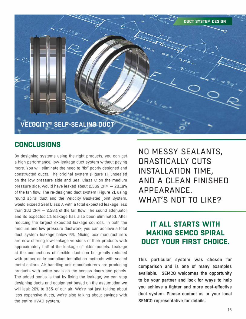
This particular system was chosen for comparison and is one of many examples available. SEMCO welcomes the opportunity to be your partner and look for ways to help you achieve a tighter and more cost-effective duct system. Please contact us or your local SEMCO representative for details.
IT ALL STARTS WITH MAKING SEMCO SPIRAL
DUCT YOUR FIRST CHOICE.
NO MESSY SEALANTS, DRASTICALLY CUTS INSTALLATION TIME, AND A CLEAN FINISHED APPEARANCE. WHAT’S NOT TO LIKE?
VELOCITY® SELF-SEALING DUCT
By designing systems using the right products, you can get a high performance, low-leakage duct system without paying more. You will eliminate the need to “fix” poorly designed and constructed ducts. The original system (Figure 1), unsealed on the low pressure side and Seal Class C on the medium pressure side, would have leaked about 2,369 CFM — 20.19% of the fan flow. The re-designed duct system (Figure 2), using round spiral duct and the Velocity Gasketed Joint System, would exceed Seal Class A with a total expected leakage less than 300 CFM — 2.56% of the fan flow. The sound attenuator and its expected 1% leakage has also been eliminated. After reducing the largest expected leakage sources, in both the medium and low pressure ductwork, you can achieve a total duct system leakage below 6%. Mixing box manufacturers are now offering low-leakage versions of their products with approximately half of the leakage of older models. Leakage at the connections of flexible duct can be greatly reduced with proper code-compliant installation methods with sealed metal collars. Air handling unit manufacturers are producing products with better seals on the access doors and panels. The added bonus is that by fixing the leakage, we can stop designing ducts and equipment based on the assumption we will leak 20% to 35% of our air. We’re not just talking about less expensive ducts, we’re also talking about savings with the entire HVAC system.
CONCLUSIONS

SEMCO® is a global leader in air
management. We are among the world’s
largest fabricators of energy-efficient spiral
pipe and fittings, acoustical enclosures, and
sound attenuators. Our collective experience
is unrivaled.
Our constant aim is to provide systems that
precisely deliver the best indoor air quality
and performance, as well as maximize
energy efficiency.
SEMCO® A FläktGroup Brand Corporate Office
1800 East Pointe Drive
Columbia, Missouri 65201 USA
573 443 1481
WE BRINGAIR TO LIFE
WE BRING AIR TO LIFE
SEMCO embraces a policy of continuous development and improvement, the right is reserved to supply products which may differ from those illustrated and described in this publication.
Certified dimensions will be supplied upon request on receipt of order.
© SEMCO LLC 2017 All Rights Reserved. SEMCO and the SEMCO logo are registered trademarks of SEMCO Incorporated. All other trademarks are registered to their respective companies.
SEM
CO E
ffici
ent D
uct S
yste
m D
esig
n BR
DAP
ww
w.s
emco
hvac
.com
WWW.SEMCOHVAC.COM | DUCT SYSTEM DESIGN | 20170405
To learn more about SEMCO offerings and to contact your nearest representative please visit www.semcohvac.com