efis-d10a electronic flight information system
TRANSCRIPT
EFIS-D10A Electronic Flight Information System
Pilot’s User Guide
Revision GFor use with firmware version 4.0
September 20, 2007
Dynon Avionics
This product is intended for the experimental and Light Sport aircraft
categories and is not approved for installation in type certificated aircraft

Contact Information Dynon Avionics, Inc. 19825 141st Place NE Woodinville, WA 98072 Phone: (425) 402-0433 Fax: (425) 984-1751 www.dynonavionics.com
Copyright © 2007 Dynon Avionics. All rights reserved. No part of this manual may be reproduced, copied, transmitted, disseminated or stored in any storage medium, for any purpose without the express written permission of Dynon Avionics. Dynon Avionics hereby grants permission to download a single copy of this manual and of any revision to this manual onto a hard drive or other electronic storage medium to be viewed for personal use, provided that such electronic or printed copy of this manual or revision must contain the complete text of this copyright notice and provided further that any unauthorized commercial distribution of this manual or any revision hereto is strictly prohibited.
Information in this document is subject to change without notice. Dynon Avionics reserves the right to change or improve its products and to make changes in the content without obligation to notify any person or organization of such changes. Visit the Dynon Avionics website (www.dynonavionics.com) for current updates and supplemental information concerning the use and operation of this and other Dynon Avionics products.

Limited Warranty Dynon Avionics warrants this product to be free from defects in materials and workmanship for three years from date of shipment. Dynon Avionics will, at its sole option, repair or replace any components that fail in normal use. Such repairs or replacement will be made at no charge to the customer for parts or labor. The customer is, however, responsible for any transportation cost. This warranty does not cover failures due to abuse, misuse, accident, improper installation or unauthorized alteration or repairs.
THE WARRANTIES AND REMEDIES CONTAINED HEREIN ARE EXCLUSIVE, AND IN LIEU OF ALL OTHER WARRANTIES EXPRESSED OR IMPLIED, INCLUDING ANY LIABILITY ARISING UNDER WARRANTY OF MERCHANTABILITY OR FITNESS FOR A PARTICULAR PURPOSE, STATUTORY OR OTHERWISE. THIS WARRANTY GIVES YOU SPECIFIC LEGAL RIGHTS, WHICH MAY VARY FROM STATE TO STATE.
IN NO EVENT SHALL DYNON AVIONICS BE LIABLE FOR ANY INCIDENTAL, SPECIAL, INDIRECT OR CONSEQUENTIAL DAMAGES, WHETHER RESULTING FROM THE USE, MISUSE OR INABILITY TO USE THIS PRODUCT OR FROM DEFECTS IN THE PRODUCT. SOME STATES DO NOT ALLOW THE EXCLUSION OF INCIDENTAL OR CONSEQUENTIAL DAMAGES, SO THE ABOVE LIMITATIONS MAY NOT APPLY TO YOU.
Dynon Avionics retains the exclusive right to repair or replace the instrument or firmware or offer a full refund of the purchase price at its sole discretion. SUCH REMEDY SHALL BE YOUR SOLE AND EXCLUSIVE REMEDY FOR ANY BREACH OF WARRANTY.
These instruments are intended for experimental aircraft only at this time. Dynon Avionics makes no claim as to the suitability of its products in connection with FAR 91.205
Dynon Avionics’ products incorporate a variety of precise, calibrated electronics. Except for replacing the optional internal backup battery in EFIS-based products per the installation guide, our products do not contain any field/user-serviceable parts. Units that have been found to have been taken apart may not be eligible for repair under warranty. Additionally, once a Dynon Avionics unit is opened up, it will require calibration and verification at our Woodinville, WA offices before it can be considered airworthy.
Table of Contents
Contact Information.............................................................................................................................................................iii Copyright.............................................................................................................................................................................iii Limited Warranty ................................................................................................................................................................ iv 1. Introduction 1-1 Before You Fly ..................................................................................................................................................................1-1 OEM Installations..............................................................................................................................................................1-1 Warning .............................................................................................................................................................................1-2 About this Guide................................................................................................................................................................1-2 2. Product Overview 2-1 EFIS-D10A Hardware .......................................................................................................................................................2-1
Power.........................................................................................................................................................................2-1 Sensors and Inputs .....................................................................................................................................................2-2 Dynon Smart Avionics Bus .......................................................................................................................................2-2 Outputs ......................................................................................................................................................................2-2 Display.......................................................................................................................................................................2-3 Buttons and Knobs.....................................................................................................................................................2-3
Theory of Operation ..........................................................................................................................................................2-3 An important note about airspeed..............................................................................................................................2-4
3. Product Operation 3-1 Front Panel Layout ............................................................................................................................................................3-1
EFIS-D10A Pilot’s User Guide v
Display...............................................................................................................................................................................3-2
Table of Contents
Screens and Pages..................................................................................................................................................... 3-2 Cycling Between Screens ......................................................................................................................................... 3-4
Menus ............................................................................................................................................................................... 3-6 Page-Sensitive Menus............................................................................................................................................... 3-6 Functionality ............................................................................................................................................................. 3-6 Flow.......................................................................................................................................................................... 3-7 Descriptions in this Guide......................................................................................................................................... 3-8
4. Available Pages 4-1 EFIS Main pages............................................................................................................................................................... 4-2 HSI Page ........................................................................................................................................................................... 4-9 Times/Auxiliary Page ....................................................................................................................................................... 4-9 Lists Pages ......................................................................................................................................................................4-10 Menu Pages......................................................................................................................................................................4-11 5. EFIS Operation 5-1 POWER – Power on/off ................................................................................................................................................... 5-1 BARO – Changing Altimeter Setting ............................................................................................................................... 5-1 BUGS – Setting Bug Markers .......................................................................................................................................... 5-2
Heading..................................................................................................................................................................... 5-2 Airspeed.................................................................................................................................................................... 5-3 Altitude ..................................................................................................................................................................... 5-4
LISTS – Using Checklists and Data Panels ...................................................................................................................... 5-5 SETUP – Setting Preferences ........................................................................................................................................... 5-6
Change displayed units ............................................................................................................................................. 5-6 Set the clock.............................................................................................................................................................. 5-6
vi EFIS-D10A Pilot’s User Guide
Show/hide display items ........................................................................................................................................... 5-8

Table of Contents
Check firmware version...........................................................................................................................................5-10 INFO – Informational Items ............................................................................................................................................5-10 DIM – Changing screen brightness .................................................................................................................................5-13 TIMER – Setting and using a timer .................................................................................................................................5-13 OATSET – Setting Temperature Offset ..........................................................................................................................5-14 6. HSI Operation 6-1 Required Connections........................................................................................................................................................6-1 Accessing the HSI/DG Page..............................................................................................................................................6-2 HSI Display Basics............................................................................................................................................................6-2 Navigation Radio Overlay .................................................................................................................................................6-5 GPS Overlay......................................................................................................................................................................6-7 HSI Menu Structure.........................................................................................................................................................6-10 7. Alerts 7-1 Alarm Indicators ................................................................................................................................................................7-1
Show Page .................................................................................................................................................................7-2 Alarm Acknowledgement..........................................................................................................................................7-2
Multiple Alarms.................................................................................................................................................................7-2 DSAB Alerts......................................................................................................................................................................7-3 8. Appendix 8-1 Appendix A: Serial Data Output........................................................................................................................................8-1
EFIS Serial Data Output ............................................................................................................................................8-2 Appendix B: PC Support Program ....................................................................................................................................8-3 Appendix C: Troubleshooting ...........................................................................................................................................8-3
EFIS-D10A Pilot’s User Guide vii
Alert Messages ..........................................................................................................................................................8-4

Table of Contents
viii EFIS-D10A Pilot’s User Guide
Appendix D: EFIS-D10A Specifications.......................................................................................................................... 8-8

1. INTRODUCTION
Thank you for purchasing the Dynon Avionics EFIS-D10A. This section provides some important cautionary information and general usage instructions for this manual.
Before You Fly We strongly recommended that you read this entire guide before attempting to use the EFIS-D10A in an actual flying situation. Additionally, we encourage you to spend time on the ground familiarizing yourself with the operation of the product. While first learning to use the instrument in the air, we recommend you have a backup pilot with you in the aircraft. Finally, we encourage you to keep this manual in the aircraft with you at all times. This document is designed to give you quick access to information that might be needed in flight. CAUTION: in a flying situation, it is the pilot’s responsibility to use the product and the guide prudently.
OEM Installations
EFIS-D10A Pilot’s User Guide 1-1
If your EFIS-D10A is installed by an OEM distributor, you may find that you are unable to access some menus and settings. Some Dynon distributors customize various areas of the EFIS-D10A firmware to maintain a consistent pilot experience and minimize integration issues across a large number of installations. Currently, OEMs can customize access levels to the following settings on Dynon systems: EMS GLOBAL setup menu, EMS SENSOR setup menu, fuel calibration, trim calibration, flaps calibration, GPS/Nav setup menu, screen configurations, and checklists/data panels. OEM distributors have the option of customizing some or all of these areas. Please contact your aircraft's manufacturer if you have any questions about how your unit has been customized.
Introduction
1-2 EFIS-D10A Pilot’s User Guide
Warning Dynon Avionics’ products incorporate a variety of precise, calibrated electronics. Except for replacing the optional internal backup battery in EFIS-based products per the installation guide, our products do not contain any field/user-serviceable parts. Units that have been found to have been taken apart may not be eligible for repair under warranty. Additionally, once a Dynon Avionics unit is opened up, it will require calibration and verification at our Woodinville, WA offices before it can be considered airworthy.
About this Guide This guide serves two purposes. The first is to help you configure and get acquainted with the EFIS-D10A’s many functions. The second is to give you quick access to vital information. For detailed technical and installation information, please refer to the EFIS-D10A Installation Guide.
In the electronic (.PDF) version of this manual, page and section references in the Table of Contents and elsewhere act as hyperlinks taking you to the relevant location in the manual. The latest version of this manual may be downloaded from our website at www.dynonavionics.com.
The following icons are used in this guide:
Any text following this icon describes functionality available only with the HS34 HSI Expansion Module connected to your system.
Any text following this icon describes functionality that is possible when multiple Dynon Avionics products are networked together via the Dynon Smart Avionics Bus (DSAB).

2. PRODUCT OVERVIEW
This section provides a general overview of the various parts of the EFIS-D10A as well as a theory of operation. The information in this section serves as a reference only and helps familiarize you with the inner workings of the unit. It should not be used for diagnostic or reparative work.
EFIS-D10A Hardware The EFIS-D10A uses solid-state sensors to provide accurate and reliable information about your flying environment in an easy-to-use interface.
POWER The EFIS-D10A requires between 10 and 30 volts DC for operation and has inputs for an external backup power supply and a keep-alive voltage. It is acceptable to have the EFIS-D10A turned on during engine start.
EFIS-D10A Pilot’s User Guide 2-1
The EFIS-D10A can be ordered with an optional internal battery which allows the instrument to continue to operate in the event of an external power failure. This lithium-ion battery is rechargeable and is managed by the EFIS-D10A. If the always-on Keep Alive circuit is connected, the EFIS-D10A continues to charge its internal battery even if the instrument is turned off. This ensures that your internal emergency battery is always fully charged. Under normal conditions, the internal battery should have a voltage between 13 and 16.8 volts. When the battery’s voltage drops below 13 volts, the EFIS-D10A displays a low battery warning. When new, a fully charged internal battery is rated for a minimum of 2 hours of normal operation with the EFIS-D10A. If the EFIS-D10A has switched to its internal emergency battery due to a power loss in your aircraft, it is advised that you land as soon as possible.

Product Overview
2-2 EFIS-D10A Pilot’s User Guide
SENSORS AND INPUTS Attitude information is obtained from 3 solid-state gyrometers, 3 solid-state accelerometers, and the airspeed pressure sensor. Heading information is obtained from 3 solid-state magnetometers housed in the EDC-D10A. Airspeed, altitude and angle of attack are obtained from three separate pressure transducers.
HSI information can be displayed when connected to Dynon’s HS34, a Garmin SL30, or a compatible GPS unit.
DYNON SMART AVIONICS BUS If you have multiple Dynon Avionics products in your aircraft, they may be networked together via the Dynon Smart Avionics Bus (DSAB). Units networked via DSAB have the ability to transmit information to each other. Any product's data can then be viewed on any other screen in the DSAB network. For example, an EFIS has the ability to display engine monitor information if it is connected to an EMS or FlightDEK-D180.
Note that the failure of a unit in a DSAB network may cause the loss of some or all data shared between units. In the above example, if the connected EMS/FlightDEK-D180 were to fail, the EFIS would no longer be able to behave as an engine monitor. For more information on DSAB-specific alerts, refer to the DSAB Alerts section on page 7-3.
OUTPUTS The EFIS-D10A has an output to drive an external customer-supplied audible device for AOA (if installed) and altitude alerts.
A serial output is also provided for serial altitude encoder data. An optional Serial-to-Gray Code Converter is available for connection to Mode C Gray Code transponders.
A connected HS34 can output voice annunciations for many of the alerts generated by the EFIS-D10A.

Product Overview
EFIS-D10A Pilot’s User Guide 2-3
DISPLAY The display is a 4-inch, 320 by 240 pixel, 450-nit LCD screen. It is acceptable to have the EFIS-D10A turned on during engine start.
BUTTONS AND KNOBS User interaction takes place via the six buttons along the bottom of the front panel of the unit.
When configured to control the EFIS-D10A, the HS34’s VALUE knob changes values when in various EFIS menus and adjusts the altimeter setting when no menus are displayed. The HS34’s HEADING and COURSE knobs affect their respective parameters on the HSI page.
Theory of Operation The primary flight instruments on your EFIS display are generated using a group of calibrated sensors. All of them are solid state – that is, there are no moving parts. These sensors include accelerometers, which measure forces in all three directions; rotational rate sensors, which sense rotation about all three axes; pressure transducers for measuring air data; and magnetometers on all three axes for measuring magnetic heading.
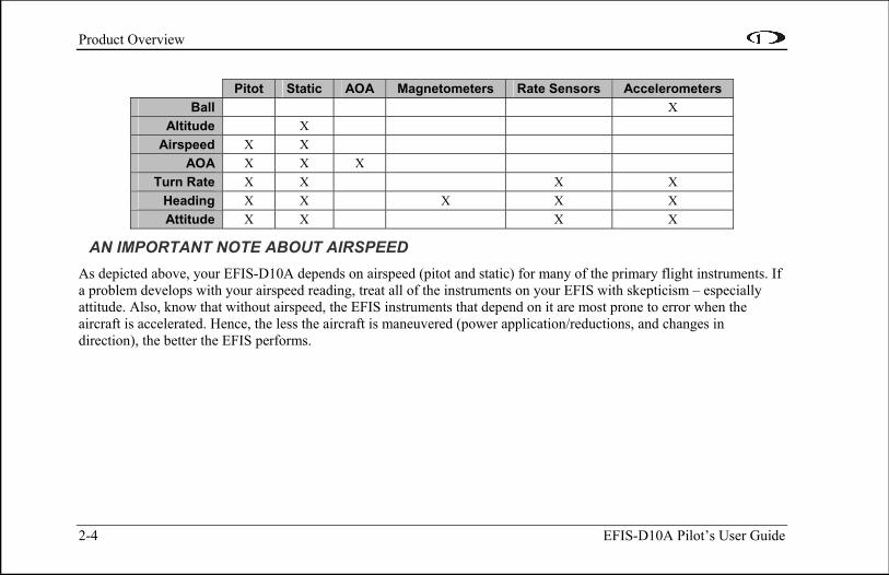
The table below describes which inputs and sensors are used within the EFIS to generate the different displayed instruments. It is not meant to enable in-flight troubleshooting, but is provided to convey how much of an integrated system your EFIS is.
Product Overview
2-4 EFIS-D10A Pilot’s User Guide
Pitot Static AOA Magnetometers Rate Sensors Accelerometers
Ball X Altitude X
Airspeed X X AOA X X X
Turn Rate X X X X Heading X X X X X Attitude X X X X
AN IMPORTANT NOTE ABOUT AIRSPEED As depicted above, your EFIS-D10A depends on airspeed (pitot and static) for many of the primary flight instruments. If a problem develops with your airspeed reading, treat all of the instruments on your EFIS with skepticism – especially attitude. Also, know that without airspeed, the EFIS instruments that depend on it are most prone to error when the aircraft is accelerated. Hence, the less the aircraft is maneuvered (power application/reductions, and changes in direction), the better the EFIS performs.

EFIS-D10A Pilot’s User Guide 3-1
3. PRODUCT OPERATION
After reading this section, you will be familiar with the basics of how to use your EFIS-D10A. For details regarding specific procedures (e.g., adjusting display brightness, changing the altimeter setting, setting the clock, etc.) please refer to the EFIS Operation section.
Front Panel Layout All normal operation of the EFIS-D10A happens via the front panel. The front panel contains buttons and a display.
• Buttons – There are six buttons on the front panel of the EFIS-D10A. Throughout this guide, these buttons are referred to as one through six, with button one being the leftmost and button six bethe rightmost. EFIS-D10A buttons are used to turn the instrument on and off, cycle between screens, scroll through menus, and adjuinstrument parameters.
ing
st
• Display – The display shows EFIS information, menus, and data obtained from other connected products.
User interaction takes place via the EFIS-D10A main display and the six buttons beneath. Note: buttons are not labeled on actual product
1 2 3 4 5 6
Product Operation
3-2 EFIS-D10A Pilot’s User Guide
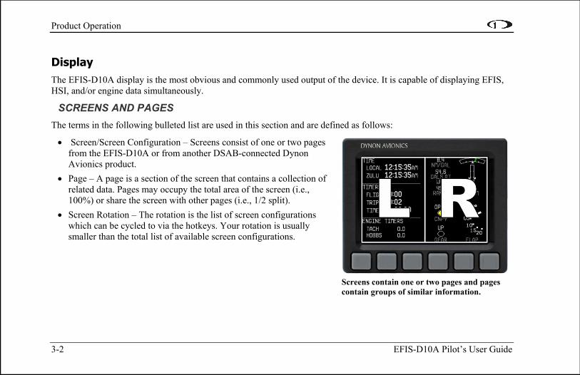
Screens contain one or two pages and pages contain groups of similar information.
Display The EFIS-D10A display is the most obvious and commonly used output of the device. It is capable of displaying EFIS, HSI, and/or engine data simultaneously.
SCREENS AND PAGES The terms in the following bulleted list are used in this section and are defined as follows:
• Screen/Screen Configuration – Screens consist of one or two pages from the EFIS-D10A or from another DSAB-connected Dynon Avionics product.
• Page – A page is a section of the screen that contains a collection of related data. Pages may occupy the total area of the screen (i.e., 100%) or share the screen with other pages (i.e., 1/2 split).
• Screen Rotation – The rotation is the list of screen configurations which can be cycled to via the hotkeys. Your rotation is usually smaller than the total list of available screen configurations.

Product Operation
Icon Left Page Area Right Page Area
1/2 1/2
One page that occupies all of the screen
area
The EFIS-D10A has several pre-defined screen configurations. The basic layout of a screen configuration is represented by one of two icons on D10-series product. The table at right shows the two icons and their meaning.
The predefined screen configurations with their respective icons are as follows:
EMS TIMES/AUX
FUEL EFIS (default EFIS-D10A boot-up screen; in default rotation) HSI (in default screen rotation)
EFIS-D10A Pilot’s User Guide 3-3
The SCREEN LIST Menu uses icons to illustrate the layout for each screen configuration.
Product Operation
3-4 EFIS-D10A Pilot’s User Guide
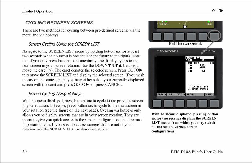
CYCLING BETWEEN SCREENS There are two methods for cycling between pre-defined screens: via the menu and via hotkeys.
Screen Cycling Using the SCREEN LIST
Navigate to the SCREEN LIST menu by holding button six for at least two seconds when no menu is present (see the figure to the right). Note that if you only press button six momentarily, the display cycles to the next screen in your screen rotation. Use the DOWN▼/UP▲ buttons to move the caret (>). The caret denotes the selected screen. Press GOTO► to remove the SCREEN LIST and display the selected screen. If you wish to stay on the same screen, you may either select your currently displayed screen with the caret and press GOTO►, or press CANCEL.
Screen Cycling Using Hotkeys
With no menu displayed, press button one to cycle to the previous screen in your rotation. Likewise, press button six to cycle to the next screen in your rotation (see the figure on the next page). Cycling via hotkeys only allows you to display screens that are in your screen rotation. They are meant to give you quick access to the screen configurations that are most important to you. If you wish to access screens that are not in your rotation, use the SCREEN LIST as described above.
With no menus displayed, pressing button six for two seconds displays the SCREEN LIST menu, from which you may switch to, and set up, various screen configurations.
Hold for two seconds
Product Operation
EFIS-D10A Pilot’s User Guide 3-5
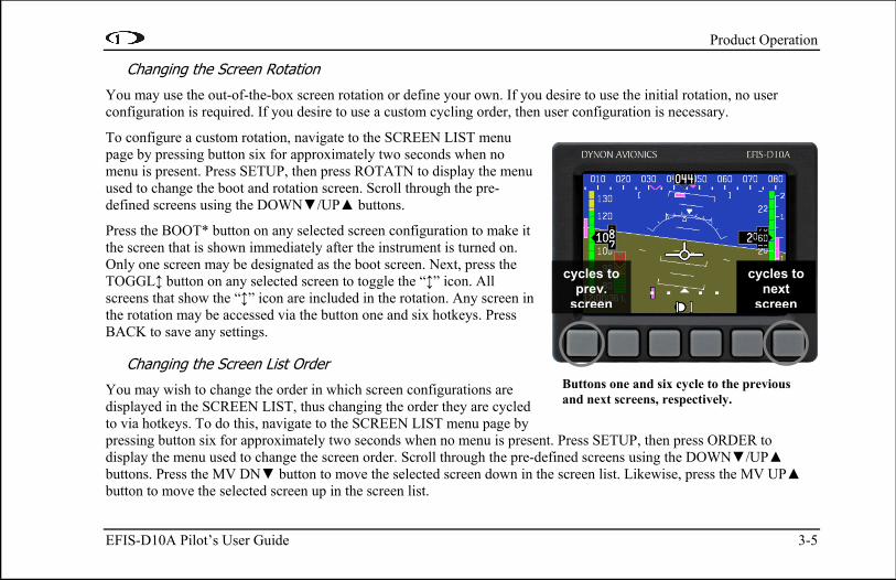
Changing the Screen Rotation
You may use the out-of-the-box screen rotation or define your own. If you desire to use the initial rotation, no user configuration is required. If you desire to use a custom cycling order, then user configuration is necessary.
To configure a custom rotation, navigate to the SCREEN LIST menu page by pressing button six for approximately two seconds when no menu is present. Press SETUP, then press ROTATN to display the menu used to change the boot and rotation screen. Scroll through the pre-defined screens using the DOWN▼/UP▲ buttons.
Press the BOOT* button on any selected screen configuration to make it the screen that is shown immediately after the instrument is turned on. Only one screen may be designated as the boot screen. Next, press the TOGGL↕ button on any selected screen to toggle the “↕” icon. All screens that show the “↕” icon are included in the rotation. Any screen in the rotation may be accessed via the button one and six hotkeys. Press BACK to save any settings.
Changing the Screen List Order
You may wish to change the order in which screen configurations are displayed in the SCREEN LIST, thus changing the order they are cycled to via hotkeys. To do this, navigate to the SCREEN LIST menu page by pressing button six for approximately two seconds when no menu is present. Press SETUP, then press ORDER to display the menu used to change the screen order. Scroll through the pre-defined screens using the DOWN▼/UP▲ buttons. Press the MV DN▼ button to move the selected screen down in the screen list. Likewise, press the MV UP▲ button to move the selected screen up in the screen list.
Buttons one and six cycle to thand next screens, respective
e previous ly.
cycles to prev.
screen
cycles to next
screen

Product Operation
3-6 EFIS-D10A Pilot’s User Guide
Menus All interaction with the EFIS-D10A is accomplished through the use of its menu system. The menu system is accessed and navigated via the six buttons located on the front of the unit.
PAGE-SENSITIVE MENUS On a screen where no menu is already present, buttons two through five are used to display a menu. With no menu displayed, pressing any one of these buttons causes the menu for the page above it to show at the bottom of the screen. For example, if a screen is divided into two pages with the left page occupying 1/2 of the screen and the right page occupying 1/2 of the screen, then pressing EFIS-D10A buttons two or three (all below the left 1/2 of the screen) displays the main menu for the left page and pressing buttons four or five (below the right 1/2 of the screen) displays the main menu for the right page (see the figure to the right).
FUNCTIONALITY A menu consists of two rows of gray boxes containing text. The upper row contains one tab that denotes the currently displayed menu. The lower row contains six labels that denote the function of the button below it. Many of the onscreen elements move up to avoid the menu. This prevents the menu from obscuring useful data while it is up. Upon exiting the menu, the screen returns to its normal appearance.
Pressing a button either displays another menu or adjusts a parameter. If there is no text above a button, then that button does not have a function in the context of that menu. Occasionally, a button label spans two or more buttons. In this case, any button below the label invokes the command.
The configuration of the pages on the screen determines which buttons are used to display a page's menu.
Product Operation
EFIS-D10A Pilot’s User Guide 3-7
If a menu contains more options than there are buttons, the MORE label is displayed over button five. Pressing this button shows you the next set of options in the current menu.
In any menu, press the BACK button to return to the previous menu and save any changes. In all top-level menus, button six is the EXIT button. Pressing EXIT removes the menu system and moves many of the onscreen elements down to their original positions.
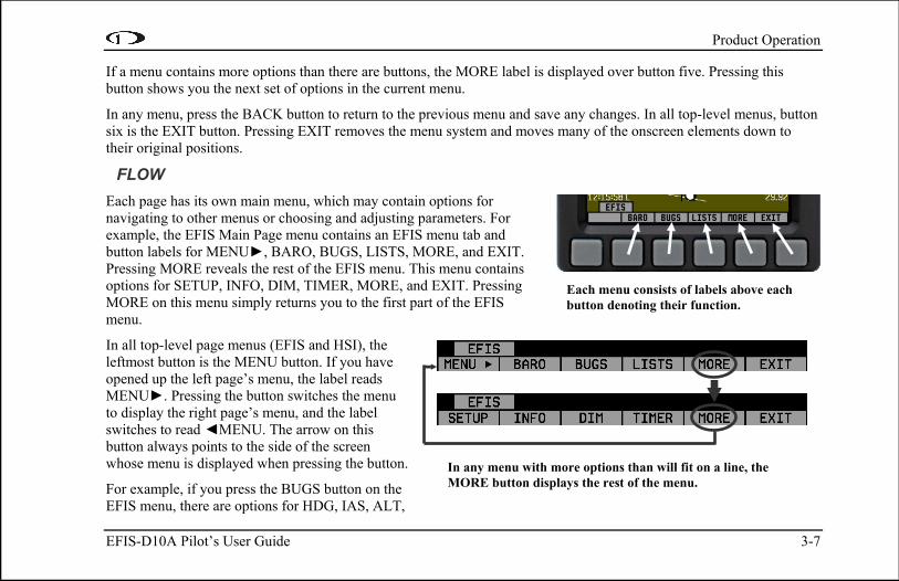
FLOW Each page has its own main menu, which may contain options for navigating to other menus or choosing and adjusting parameters. For example, the EFIS Main Page menu contains an EFIS menu tab and button labels for MENU►, BARO, BUGS, LISTS, MORE, and EXIT. Pressing MORE reveals the rest of the EFIS menu. This menu contains options for SETUP, INFO, DIM, TIMER, MORE, and EXIT. Pressing MORE on this menu simply returns you to the first part of the EFIS menu.
In all top-level page menus (EFIS and HSI), the leftmost button is the MENU button. If you have opened up the left page’s menu, the label reads MENU►. Pressing the button switches the menu to display the right page’s menu, and the label switches to read ◄MENU. The arrow on this button always points to the side of the screen whose menu is displayed when pressing the button.
For example, if you press the BUGS button on the EFIS menu, there are options for HDG, IAS, ALT,
Each menu consists of labels above each button denoting their function.
In any menu with more options than will fit on a line, the MORE button displays the rest of the menu.

Product Operation
3-8 EFIS-D10A Pilot’s User Guide
and EXIT. Pressing HDG, IAS, or ALT allows the user to configure heading, indicated airspeed, or altitude bugs, respectively.
To exit the menu system, press the BACK button as many times as is needed to reach an EXIT button. This varies based upon how deep you are into the menu system.
DESCRIPTIONS IN THIS GUIDE Throughout this guide, the “>” character is used to indicate entering a deeper level of the menu system. For example, “EFIS > INFO > LEFT” indicates entering the EFIS menu, pressing MORE, then pressing INFO, and then pressing LEFT to enter the left info item menu. Note that the MORE button is not included in the sequence, since pressing MORE reveals more options in the same level of the menu system.
4. AVAILABLE PAGES
The EFIS main pages use various tapes, digital displays, and other indicators overlaid on an artificial horizon. On the 2/3 and full-screen pages, you may also display up to two “info items” on the left and right side of the main page. HSI pages use text and a DG style compass by itself or overlaid with lines and arrows of different colors.
Note: HSI pages use data that is obtained from a source external to the EFIS-D10A. Refer to the EFIS-D10A Installation Manual for a list of compatible equipment.
EFIS-D10A Pilot’s User Guide 4-1
Note: EMS-based pages use data that is obtained from Dynon’s EMS products. You may only display these pages on your EFIS-D10A if you own a Dynon EMS-based product, and the two units are connected via DSAB. Refer to the EFIS-D10A Installation Manual for details regarding proper connection between Dynon products and other devices in your system. Please see your EMS-based product’s Pilot’s User Guide for information on configuring the various displays sourced from it.

Available Pages
4-2 EFIS-D10A Pilot’s User Guide
EFIS Main pages Available in full-page format
The EFIS-D10A default screen rotation includes only 2/3 EFIS pages combined with the various EMS and HSI pages described below. However, you may also choose screen configurations that use 1/3 and full-screen pages. The 2/3 and full-screen pages can display EFIS- and EMS-related info items on the left and right side of the screen. You can enable any of the non-default EFIS screens as described in the Changing the Screen Rotation section on page 3-5. Some of the displayed items described below may not be onscreen, depending on whether or not they have been enabled in the CLUTTR menu.
Beginning with firmware revision 3.0, Dynon adopted a dramatically different EFIS display format than it had previously used. If your EFIS display does not resemble the layouts shown at right, first ensure that you are using firmware version 3.0 or higher. Then, ensure that the setting at EFIS > SETUP > STYLE is set to MODERN. Iyou prefer the previous display style, you can change this setting to CLASSIC. The classic display format is documentein previous revisions of this manual, which can be found at our website. No further developme
f d
nt will occur on the classic
The following sub-sections describe the displayed items in detail.
display format.

Available Pages
EFIS-D10A Pilot’s User Guide 4-3
Horizon line, pitch and roll indicators
Bounded on the top by blue, and on the bottom by brown, the horizon line behaves in much the same way as a traditional gyro-based artificial horizon. Unlike a mechanical artificial horizon, the EFIS-D10A’s horizon has no roll or pitch limitation. The horizon line stays parallel to the Earth’s horizon line regardless of attitude. The parallel lines above and below the horizon line are the pitch indicator lines, with each line indicating 5 degrees of pitch. The end of each 10º pitch indicator line has a hooked barb that points towards the horizon line to aid attitude awareness.
The roll scale has tic marks at 10, 20, 30, 45, 60, and 90 degrees of roll. In the CLUTTR menu (described on page 5-8), you can choose between a stationary roll indicator and one that rotates along with the horizon. The stationary roll indicator (type 1 in the EFIS > SETUP > CLUTTR > ROLL menu) has an internal arrow which moves to stay perpendicular to the horizon, like a jet EFIS presentation. The moving roll indicator (type 2) rotates the scale about a stationary internal arrow which points to the current roll angle on the scale, like most mechanical attitude instrument presentations.
CDI/Glideslope Indicators
When the EFIS-D10A is receiving CDI or glideslope information from a GPS or nav radio, they can be displayed on the main EFIS display as well as the on the full HSI page (as described in the HSI Operation section on page 6-1). The data source is chosen on the HSI page using the NAVSRC button; the EFIS and HSI CDI/GS displays are always synchronized to the same source. There is no way to change the source on the EFIS screen.
On the EFIS page, these two items are enabled via the EFIS > SETUP > CLUTTR menu under a single item, which can be set to either CDI:N, CDI:Y, or CDI+GS.

Available Pages
4-4 EFIS-D10A Pilot’s User Guide
The CDI is located just above the slip/skid ball when displayed, and behaves much as described in the HSI Operation section on page 6-1. The CDI needle is green when sourced from a nav radio and magenta when sourced from GPS. When to/from information is available, the center of the CDI is an arrow; when on an ILS, it is a filled-in square.
The glideslope indicator is located to the left of the roll scale tape, and behaves much as described in the HSI Operation section on page 6-1. The GS needle is green when sourced from a nav radio and magenta when sourced from GPS, and appears only when tuned to an ILS or a GPS source with vertical guidance.
Due to screen space limitations, turning on the glideslope prevents a left info item from being displayed on the 2/3-screen EFIS page. Additionally, at extreme roll angles, the glideslope is hidden to provide space for other screen elements.
Stabilized heading tape and digital readout
Located at the top of the EFIS page, the heading indicator functions much like a standard slaved directional gyro. North, East, South, and West directions are labeled on the tape, “N,” “E,” “S,” and “W,” respectively. The digital readout displays your current heading, while the surrounding tape scrolls beneath its arrow. You may set a yellow bug on this tape as a heading reminder. The pointer in the digital readout is hollow to allow the GPS ground track indicator, displayed as a magenta arrow, to show through. A difference between the ground track arrow and the current heading indicates that some wind is present. The currently set course heading is represented by a “V,” colored green when sourced from a nav radio and magenta when sourced from GPS. When the CDI is centered, aligning the ground track pointer within the course pointer compensates for all wind and takes you directly to the waypoint or VOR. For course and ground track to be displayed on the heading tape, they must both be enabled in the CLUTTR menu.
Like a conventional gyro-stabilized magnetic compass, magnetic heading reacts immediately to turn rate so that heading changes are reflected immediately. It then uses magnetometer data over the long term to ensure that it remains correct. Additionally, heading is corrected for attitude so that it is accurate as you pitch and roll.

Available Pages
EFIS-D10A Pilot’s User Guide 4-5
Turn rate indicator
Centered just below the heading digital readout, the turn rate indicator displays the aircraft’s current rate of turn with respect to the ground. The magenta bar grows in the direction that the aircraft is currently turning, and is anchored at a white vertical anchor line. The brackets on either side of the bar’s anchor line represent the turn rate which results in a standard rate turn. Turn rate takes attitude into account. This means that even when you are highly banked, it still shows rate of turn in relation to the aircraft’s heading.
The turn rate indicator is scaled to indicate a 6-second heading trend. In the example above, the trend indicator is showing that the aircraft will be pointed at 40º in 6 seconds if the rate of turn does not change.
Altitude tape, digital readout, and VSI
The altitude tape scrolls beneath the altitude digital readout and arrow. The digital readout’s digits scroll up and down, simulating an analog altimeter and giving a sense of the direction of movement. Thousands of feet are displayed using large numbers while hundreds of feet are displayed in smaller numbers. The EFIS-D10A accurately displays altitudes from -1200 to 30,000 ft (-365 to 9144 m).
The graphical Vertical Speed Indicator is located next to the altitude tape. The magenta bar grows in the direction of – and in proportion to – the rate of climb or descent. The numbers on the scale represent thousands of feet per minute. In the CLUTTR menu, the VSI scale can be set to display 1000 ft/min, 2000 ft/min, and 4000 ft/min. The 2000 ft/min scale is linear throughout the range, while the 1000 ft/min and 4000 ft/min are non-linear as shown on the scale. When set to display 2000 ft/min, the VSI bar is scaled to indicate a 6-second altitude trend based on its position with relation to the altitude bar. When set to display 4000 ft/min, the VSI bar is scaled to indicate a 6-second trend only up to 1000 ft/min. When set to display 1000 ft/min, the VSI bar is scaled to indicate a 12-second trend up to 500 ft/min.
Available Pages
4-6 EFIS-D10A Pilot’s User Guide
During the first 30 seconds of operation, the altitude tape and digital readout are not displayed as the unit needs a small amount of time before altitude measurements are deemed accurate.
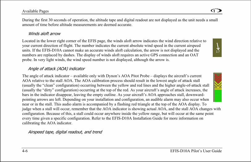
Winds aloft arrow
Located in the lower right corner of the EFIS page, the winds aloft arrow indicates the wind direction relative to your current direction of flight. The number indicates the current absolute wind speed in the current airspeed units. If the EFIS-D10A cannot make an accurate winds aloft calculation, the arrow is not displayed and the numbers are replaced by dashes. The display of winds aloft requires an active GPS connection and an OAT probe. In very light winds, the wind speed number is not displayed, although the arrow is.
Angle of attack (AOA) indicator
The angle of attack indicator – available only with Dynon’s AOA Pitot Probe – displays the aircraft’s current AOA relative to the stall AOA. The AOA calibration process should result in the lowest angle of attack stall (usually the “clean” configuration) occurring between the yellow and red lines and the higher angle-of-attack stall (usually the “dirty” configuration) occurring at the top of the red. As your aircraft’s angle of attack increases, the bars in the indicator disappear, leaving the empty outline. As your aircraft’s AOA approaches stall, downward-pointing arrows are left. Depending on your installation and configuration, an audible alarm may also occur when near or in the stall. This audio alarm is accompanied by a flashing red triangle at the top of the AOA display. To judge when a stall will occur, remember that the AOA indicator is showing actual AOA, and the stall AOA changesconfiguration. Because of this, a stall could occur anywhere inside the yellow range, but will occur at the same point every time given a specific configuration. Refer to the EFIS-D10A Installation Guide for more information on calibrating the AOA indicator.
with
Airspeed tape, digital readout, and trend

Available Pages
EFIS-D10A Pilot’s User Guide 4-7
The airspeed tape scrolls beneath the airspeed digital readout and arrow. The digital readout’s digits scroll up and down, simulating an analog airspeed indicator and giving a sense of the increase or decrease in speed. The EFIS-D10A is factory-calibrated to be accurate for airspeeds between 15 and 325 knots (17 to 374 mph). As airspeed increases from 0 knots, the indicator becomes active at 20 knots. The indicator remains active until airspeed drops below 15 knots. The EFIS-D10A may display airspeeds above 325 knots, but it is not guaranteed to be accurate.
The airspeed tape utilizes 4 colors to give you a graphical representation of your speed with relation to your aircraft’s limits. By default all of the color thresholds are set at 0, causing a grey tape to be displayed. You must set the values of the airspeed color thresholds via the SETUP menu. Refer to the EFIS-D10A Installation Guide for more information on setting the airspeed color thresholds.
The airspeed trend indicator is located to the left of the airspeed tape. The magenta bar grows in the direction of—and in proportion to—the rate of acceleration or deceleration. The trend indicator is scaled to indicate a 6-second airspeed trend. In the example at right, the trend indicator is showing that the aircraft will reach 119 knots in 6 seconds if airspeed does not change.
Bugs
Bugs may be set to mark a desired heading, airspeed, or altitude. These bugs are represented by a yellow inverted arrow located at the desired value on the tape. If the set heading, altitude, or airspeed is currently off-screen, the bug icon appears at the edge of the moving tape closest to the desired value. Your airspeed, heading, or altitude is at its set bug value when the bug’s inverted triangle encloses the triangle of the digital readout’s pointer. The altitude bug also acts as an altitude alerter; see BUGS – Setting Bug Markers on page 5-2 for more information.
Slip/skid ball

Available Pages
4-8 EFIS-D10A Pilot’s User Guide
The slip/skid ball works much like a standard mechanical gauge. It is a visual representation of lateral acceleration. If the ball is within the two vertical lines, then you are in coordinated flight.
Altimeter setting display
The current altimeter setting is displayed at the bottom right of the screen below the altitude tape. The value is shown in either inches of Mercury or millibars depending on your preference set in the EFIS > BARO menu.
Clock/timer
The clock is displayed in the lower left-hand corner of the screen, below the airspeed tape. To set the clock, enter the EFIS > SETUP > CLOCK submenu. When a count-down or count-up timer is enabled, it is displayed in place of the clock until the timer is stopped. The character next to the clock indicates whether the unit is displaying Local time (L), Zulu time (Z), or a timer (T). If a GPS is connected to your Dynon network and is outputting time information, the Zulu time of all connected products is auto-set to that reported by the GPS.
Available Pages
EFIS-D10A Pilot’s User Guide 4-9
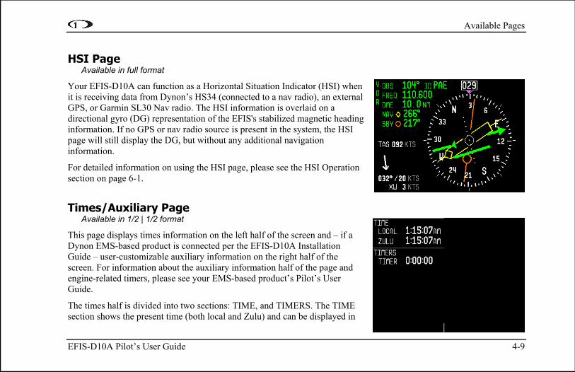
HSI Page Available in full format
Your EFIS-D10A can function as a Horizontal Situation Indicator (HSI) when it is receiving data from Dynon’s HS34 (connected to a nav radio), an external GPS, or Garmin SL30 Nav radio. The HSI information is overlaid on a directional gyro (DG) representation of the EFIS's stabilized magnetic heading information. If no GPS or nav radio source is present in the system, the HSI page will still display the DG, but without any additional navigation information.
For detailed information on using the HSI page, please see the HSI Operation section on page 6-1.
Times/Auxiliary Page Available in 1/2 | 1/2 format
This page displays times information on the left half of the screen and – if a Dynon EMS-based product is connected per the EFIS-D10A Installation Guide – user-customizable auxiliary information on the right half of the screen. For information about the auxiliary information half of the page and engine-related timers, please see your EMS-based product’s Pilot’s User Guide.
The times half is divided into two sections: TIME, and TIMERS. The TIME section shows the present time (both local and Zulu) and can be displayed in

Available Pages
4-10 EFIS-D10A Pilot’s User Guide
either standard or military time formats. The TIMERS section contains the general purpose timer which can be used for a variety of purposes. Additional timers will be displayed in this section if you have a Dynon EMS-based product connected.
Lists Pages Available in full format
This page displays user-defined checklists and data panels to be used for waypoint information, lists of radio frequencies, or other informational purposes. You may define up to twenty-five lists. Each checklist/data panel can contain up to 14 lines of text and 40 characters per line.
Checklists/data panels must be defined and uploaded to the EFIS-D10A as described by the Dynon Product Support Program. Reference the help file that accompanies this software for more information. To download the Dynon Product Support Program, visit www.dynonavionics.com/downloads.

Available Pages
Menu Pages Available in full format
Some setup menus require a full page to display all the available options. Menu Pages use a caret symbol (“>”) to indicate the currently selected line. Use the DOWN▼ and UP▲ buttons to scroll through the list of options.
Any line on a Menu Page that is followed by ► has more options to configure inside of it. Press SEL► to expand the menu into another list of options to the right.
Any line on a Menu Page that is not followed by ► indicates that its value can be modified using the SEL►, DOWN▼, and UP▲ buttons.
EFIS-D10A Pilot’s User Guide 4-11


5. EFIS OPERATION
This section guides you through each of the EFIS main page menu selections and their sub-menus. To enter the EFIS menu system, press any button (except for buttons 1 and 6) directly beneath an EFIS main page. If no EFIS main page is displayed, you must switch to a screen configuration that includes and EFIS main page as described on page 3-4.
POWER – Power on/off When the EFIS-D10A is turned off but still has a power source via one of the three power inputs, press the far left button to turn the unit on. Likewise, once the unit is on and no menus are displayed, push and hold the leftmost button to turn it off. While power is still connected, the unit is never fully turned off. It simply enters an extremely low-power state, allowing it to keep track of time. It is acceptable to have the EFIS-D10A on during engine crank. It immediately powers on upon application of external power.
BARO – Changing Altimeter Setting In the EFIS > BARO menu, you can adjust the altimeter setting. When the BARO menu is displayed, the value-setting box shows the current altimeter setting. The DEC- and INC+ buttons change the altimeter setting by 1/100th inHg or 1 mbar, depending upon your selected units. As you change the altimeter setting, the altitude indicators change accordingly. Adjust the altimeter setting until the altitude indicators display the correct altitude for your location or the altimeter setting matches the current barometric pressure value.
EFIS-D10A Pilot’s User Guide 5-1

EFIS Operation
5-2 EFIS-D10A Pilot’s User Guide
The altimeter setting can be set in units of inches of mercury (inHg) or millibars (mb). To change the units, simply press buttons 1 or 2, corresponding to the UNITS label. To reset the altimeter setting to standard day pressure (29.92 inHg), press button 3, corresponding to 29.92 (inHg) or 1013 (mb).
With no menus displayed, rotating the HS34’s VALUE knob adjusts the altimeter setting. Push and hold the value knob for more than 1 second to set the altimeter setting to 29.92 inHg.
The current indicated altitude is preserved across a power cycle. When powered down, the instrument saves the indicated altitude. When it is powered up again, the instrument automatically adjusts the altimeter setting by exactly enough to preserve that saved value. This is not a replacement for modifying the altimeter setting by the pilot before takeoff; it makes it very close to the correct value, minimizing the amount of adjustment needed. To turn auto-set on or off, enter the EFIS > SETUP > BARO menu and set the ADJUST AT BOOT option to ON or OFF.
BUGS – Setting Bug Markers You can set a marker – or “bug”– to display on any or all of the three tapes. To do this, enter the EFIS > BUGS menu, and choose the type of bug to configure: HDG (heading), IAS (Indicated Airspeed), or ALT (altitude). Note that if a bug is not currently displayed, changing its set value causes it to display on the relevant tape.
HEADING In the BUGS menu, press HDG. Press the TOGGLE button to turn on or off the heading bug display on the horizontal heading tape. Note that this affects the display of the heading bug on the HSI page as well.

EFIS Operation
EFIS-D10A Pilot’s User Guide 5-3
In the HDG bug menu the value-setting box is displayed in the lower part of the display. Press SEL► to select which digit to change and DEC- and INC+ to change the selected digit. Press the SYNC button to synchronize the heading bugto your current heading. As you increment or decrement the heading bug value it rolls over at 360 degrees, returning value to 001. If you have the heading bug displayed, the ma
the
rker moves left or right along the tape as you change its value.
The heading bug can be adjusted on any EFIS page displayed in the system and is synchronized across all EFIS-based units.
The heading bug can be adjusted at any time by rotating the HS34’s HEADING knob. If the bug is currently toggled off, rotating the HEADING knob causes the bug to be displayed on the heading tape. To sync the bugyour current heading, press the heading
to knob briefly. To toggle the heading bug on or off, push and hold the
knob for more than 1 second.
irspeed. If you have the airspeed bug displayed, the marker moves up or down the airspeed tape as you change
heading
AIRSPEED In the BUGS menu, press IAS. Press the TOGGLE button to turn on or off the heading bug display on the horizontal heading tape.
In the IAS bug menu the value-setting box is displayed in the lower part of the display. Press SEL► to select which digit to change and DEC- and INC+ to change the selected digit. Press the SYNC button to synchronize the airspeed bug to your current indicated aits value.
The airspeed bug can be adjusted on any EFIS page in the system and is synchronized across all EFIS-based units.
When in the BUGS > IAS menu, rotate the HS34’s VALUE knob to quickly change the bug’s set value.
EFIS Operation
5-4 EFIS-D10A Pilot’s User Guide
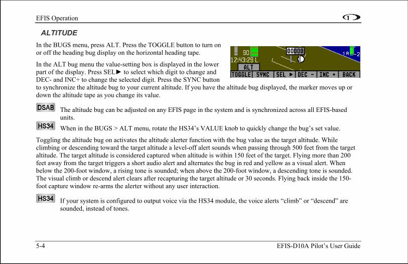
ALTITUDE In the BUGS menu, press ALT. Press the TOGGLE button to turn on or off the heading bug display on the horizontal heading tape.
In the ALT bug menu the value-setting box is displayed in the lower part of the display. Press SEL► to select which digit to change and DEC- and INC+ to change the selected digit. Press the SYNC button to synchronize the altitude bug to your current altitude. If you have the altitude bug displayed, the marker moves up odown the altitude tape as you change its value.
r
The altitude bug can be adjusted on any EFIS page in the system and is synchronized across all EFIS-based units.
When in the BUGS > ALT menu, rotate the HS34’s VALUE knob to quickly change the bug’s set value.
Toggling the altitude bug on activates the altitude alerter function with the bug value as the target altitude. While climbing or descending toward the target altitude a level-off alert sounds when passing through 500 feet from the target altitude. The target altitude is considered captured when altitude is within 150 feet of the target. Flying more than 200 feet away from the target triggers a short audio alert and alternates the bug in red and yellow as a visual alert. When below the 200-foot window, a rising tone is sounded; when above the 200-foot window, a descending tone is sounded. The visual climb or descend alert clears after recapturing the target altitude or 30 seconds. Flying back inside the 150-foot capture window re-arms the alerter without any user interaction.
If your system is configured to output voice via the HS34 module, the voice alerts “climb” or “descend” are sounded, instead of tones.
EFIS Operation
EFIS-D10A Pilot’s User Guide 5-5
To simulate the altitude alerter on the ground, SYNC the altitude bug to your current altitude and then adjust the altimeter setting up or down. When you adjust the altimeter setting enough that the altitude is outside the 200-foot window, observe that the audio alert triggers and the bug alternates red and yellow.
LISTS – Using Checklists and Data Panels The Dynon Support Program allows you to enter your own checklists or select from included data panels. These checklists and data panels can then be uploaded to your EFIS-D10A for quick access from the main menu or from your screen rotation. Data panels and checklists can be included beneath 5 user-configurable categories and each category can contain up to 5 checklists or data panels. By default the EFIS-D10A is loaded with the following 5 categories: CHKLIST, RADIO, POH, EMGNCY and MISC. Each checklist/data panel can contain up to 14 lines of text and 40 characters per line.
To load checklists and data panels onto your EFIS-D10A, you must upload them as described in the Dynon Product Support Program help file. Pushing the LIST button displays the 5 main categories as set up in the Dynon Support Program. Press a button corresponding to the desired category to show the checklists and data panels beneath it. When you display a checklist, it takes up the entire screen. See the Dynon Support Program for more detailed information on entering checklists and data panels. It can be downloaded from our website at www.dynonavionics.com/downloads.

EFIS Operation
5-6 EFIS-D10A Pilot’s User Guide
SETUP – Setting Preferences Enter the EFIS > SETUP menu to make changes to preferences. Many of the settings in this menu should only be changed by the installer, and are described in the EFIS-D10A Installation Guide. The preferences and settings that are relevant to the pilot and in-flight operation are explained below.
CHANGE DISPLAYED UNITS In the UNITS submenu, you may change the system-wide displayed units for the following units. See the following table for a list of available units for each displayed parameter.
In a DSAB network, unit preferences are shared between all connected instruments.
SET THE CLOCK Entering the EFIS > SETUP > CLOCK menu displays the local and Zulu times in the value-setting box. Because local time is usually an offset in hours from Zulu time, set the minutes value in the Zulu time portion of the box; notice that the local time minutes setting change at the same time. Then, set the hours for local and Zulu times independently. Once you have set Zulu time, you should never need to change it, as it is independent of daylight saving time. When connected
Parameter Available units Airspeed (IAS) Knots, miles/hour, kilometers/hour Altitude (ALT) Feet, meters
Temperature (TEMP) Celsius, Fahrenheit Barometric Pressure (BARO) inHg, mbar
Distance (DIST) Nautical miles, statutory miles, kilometers
EFIS Operation
EFIS-D10A Pilot’s User Guide 5-7
to a GPS which is outputting time information, Zulu time is synchronized to the GPS and cannot be set on the EFIS-D10A.
In a DSAB network, you can only set the Zulu time on the DSAB master, and only if it is not synchronized to GPS time. You can set the local time on all units individually.
To change the local clock when moving through time zones or to enter daylight saving time, simply change only the hours (and, if necessary for the time zone, the half-hour offset) for the local time. Be aware that connecting to the EFIS-D10A with the Dynon Product Support Program resets the time; do not set the time until you have performed all of the PC interface operations. Refer to the following set of tips as you set the clock:
• Set both the local and Zulu times in military time. You have may display the time in either military or standard 12-hour format, as described below.
• SEL► moves the highlight to the next set of digits. The order of selection is 1. Local hours, 2. Local minutes (adjustable only as ½-hour offsets from Zulu minutes), 3. Zulu hours, 4. Zulu minutes. When connected to a GPS, you are not permitted to adjust the Zulu time on the EFIS-D10A
• DEC- and INC+ change the selected set of digits. To speed up the process, press and hold the desired button. If you pass the desired value, you may simply back down to it by pressing the button corresponding to the opposite direction.
• Incrementing or decrementing the minutes digits resets the second count.
• In the CLOCK > FORMAT menu, press LC/ZU to change between local and Zulu time display on the EFIS page. Press 12/24 to change between standard and military time display on the EFIS page
EFIS Operation
5-8 EFIS-D10A Pilot’s User Guide
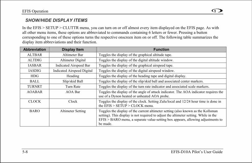
SHOW/HIDE DISPLAY ITEMS In the EFIS > SETUP > CLUTTR menu, you can turn on or off almost every item displayed on the EFIS page. As with all other menu items, these options are abbreviated to commands containing 6 letters or fewer. Pressing a button corresponding to one of these options turns the respective onscreen item on or off. The following table summarizes the display item abbreviations and their function.
Abbreviation Display Item Function ALTBAR Altimeter Bar Toggles the display of the graphical altitude tape. ALTDIG Altimeter Digital Toggles the display of the digital altitude window. IASBAR Indicated Airspeed Bar Toggles the display of the graphical airspeed tape. IASDIG Indicated Airspeed Digital Toggles the display of the digital airspeed window.
HDG Heading Toggles the display of the heading tape and digital display. BALL Slip/skid Ball Toggles the display of the slip/skid ball and associated center markers.
TURNRT Turn Rate Toggles the display of the turn rate indicator and associated scale markers. AOABAR AOA Bar Toggles the display of the angle of attack indicator. The AOA indicator requires the
use of a Dynon heated or unheated AOA probe. CLOCK Clock Toggles the display of the clock. Setting Zulu/local and 12/24 hour time is done in
the EFIS > SETUP > CLOCK menu. BARO Altimeter Setting Toggles the display of the current altimeter setting (also known as the Kollsman
setting). This display is not required to adjust the altimeter setting. While in the EFIS > BARO menu, a separate value-setting box appears, allowing adjustments to be made.

EFIS Operation
EFIS-D10A Pilot’s User Guide 5-9
Abbreviation Display Item Function ROLL Roll Scale Toggles and configures the display of the roll scale. When set to “N”, the roll scale
is not displayed. When set to “1,” the roll scale stays fixed on the screen and the pointer moves along the scale, like a jet EFIS presentation. When set to “2”, the roll scale moves with the horizon, while the pointer stays fixed on the screen, like most mechanical attitude instrument presentations.
GTRK Ground Track Toggles the display of the ground track indicator on the heading tape. The track indicator is a magenta arrow and is only displayed when the EFIS-D10A is receiving valid GPS data from an external source. If the GTRK button status displays “Y” and no ground track arrow is displayed, the EFIS-D10A cannot detect your GPS, or the GPS does not yet have a satellite lock.
WIND Winds Aloft Toggles the display of the wind arrow and speed indicator. The display of winds aloft requires an active GPS connection and an OAT probe. If the WIND button status displays “Y” and no wind indicator is displayed onscreen, the EFIS-D10A cannot detect your GPS, the GPS does not yet have a satellite lock, the FlightDEK-D180 does not have a connection to the remote compass (EDC) or the FlightDEK-D180 does not have an OAT.
ASTRND Airspeed Trend Toggles the display of the 6-second airspeed trend indicator next to the IAS tape. VSI Vertical Speed Indicator Toggles and configures the display of the VSI tape next to the altitude tape. The
VSI can be hidden (“N”), or can be set to 1k, 2k, or 4k ft/min scaling. The 2000 ft/min display is linear throughout the range, while the 1000 and 4000 ft/min displays incorporate a non-linear scale to increase low vertical speed resolution.
EFIS Operation
5-10 EFIS-D10A Pilot’s User Guide
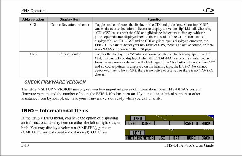
Abbreviation Display Item Function CDI Course Deviation Indicator Toggles and configures the display of the CDI and glideslope. Choosing “CDI”
causes the course deviation indicator to display above the slip/skid ball. Choosing “CDI+GS” causes both the CDI and glideslope indicators to display, with the glideslope indicator displayed next to the roll scale. If the CDI button status displays “Y” or “CDI+GS” and no CDI or glideslope is displayed onscreen, the EFIS-D10A cannot detect your nav radio or GPS, there is no active course, or there is no NAVSRC chosen on the HSI page.
CRS Course Pointer Toggles the display of a “V”-shaped course pointer on the heading tape. Like the CDI, this can only be displayed when the EFIS-D10A is receiving a valid course from the nav source selected on the HSI page. If the CRS button status displays “Y” and no course pointer is displayed on the heading tape, the EFIS-D10A cannot detect your nav radio or GPS, there is no active course set, or there is no NAVSRC chosen.
CHECK FIRMWARE VERSION The EFIS > SETUP > VRSION menu gives you two important pieces of information: your EFIS-D10A’s current firmware version; and the number of hours the EFIS-D10A has been on. If you require technical support or other assistance from Dynon, please have your firmware version ready when you call or write.
INFO – Informational Items In the EFIS > INFO menu, you have the option of displaying an informational display item on either the left or right side, or both. You may display a voltmeter (VMETER), g-m(GMETER), vertical speed indicator (VSI), OAT/true
eter
EFIS Operation
EFIS-D10A Pilot’s User Guide 5-11
airspeed/ density altitude (OAT), and engine RPM/MAP info (ENGINE). More detail about each of these is given below.
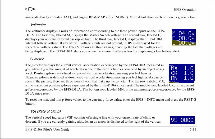
Voltmeter
The voltmeter displays 3 rows of information corresponding to the three power inputs on the EFIS-D10A. The first row, labeled M, displays the Master Switch voltage. The second row, labeled E, displays your optional external backup voltage. The third row, labeled I, displays the EFIS-D10A internal battery voltage. If any of the 3 voltage inputs are not present, 00.0V is displayed for the respective voltage values. The letter V follows all three values, denoting the fact that voltages are being displayed. The EFIS-D10A alerts you when the internal battery is low by displaying a low battery alert.
G-meter
The g-meter displays the current vertical acceleration experienced by the EFIS-D10A measured in g’s, where 1 g is the amount of acceleration due to the earth’s field experienced by an object at sea level. Positive g-force is defined as upward vertical acceleration, making you feel heavier. Negative g-force is defined as downward vertical acceleration, making you feel lighter. As can be seen in the picture, there are three rows of text that make up the g-meter. The top row, labeled MX, is the maximum positive g-force experienced by the EFIS-D10A since reset. The middle row, labeled CR, is the current g-force experienced by the EFIS-D10A. The bottom row, labeled MN, is the minimum g-force experienced by the EFIS-D10A since reset.
To reset the max and min g-force values to the current g-force value, enter the EFIS > INFO menu and press the RSET G button.
VSI (Rate of Climb)
The vertical speed indicator (VSI) consists of a single line with your current rate of climb or descent. If you are currently gaining altitude, an up arrow is displayed to the right of the vertical
5-12 EFIS-D10A Pilot’s User Guide
speed value. If you are losing altitude, a down arrow is displayed to the right of the vertical speed value. The units of VSI are feet/minute. Note that in the MODERN display (EFIS > SETUP > STYLE), found in EFIS-D10A firmware version 3.0 and higher, VSI can be displayed as a graphical indicator next to the altitude tape.
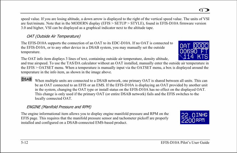
OAT (Outside Air Temperature)
The EFIS-D10A supports the connection of an OAT to its EDC-D10A. If no OAT is connected to the EFIS-D10A, or to any other device in a DSAB system, you may manually set the outside temperature.
The OAT info item displays 3 lines of text, containing outside air temperature, density altitude, and true airspeed. To use the TAS/DA calculator without an OAT installed, manually enter the outside air temperature in the EFIS > OATSET menu. When a temperature is manually input via the OATSET menu, a box is displayed around the temperature in the info item, as shown in the image above.
When multiple units are connected to a DSAB network, one primary OAT is shared between all units. This can be an OAT connected to an EFIS or an EMS. If the EFIS-D10A is displaying an OAT provided by another unit in the system, changing the OAT type or install status on the EFIS-D10A has no effect on the displayed OAT. This change is only used if the primary OAT (or entire DSAB network) fails and the EFIS switches to the locally connected OAT.
ENGINE (Manifold Pressure and RPM)
The engine informational item allows you to display engine manifold pressure and RPM on the EFIS page. This requires that the manifold pressure sensor and tachometer pickoff are properly installed and configured on a DSAB-connected EMS-based product.

EFIS Operation
EFIS-D10A Pilot’s User Guide 5-13
DIM – Changing screen brightness In the EFIS > DIM menu, press BRITR or DRKR to change the brightness of the display. It is not possible to turn the screen completely black. Note that if power to the EFIS-D10A is cycled, the screen is reset to full brightness.
The DIM function also exists in the EMS main page menu. You may dim the display via either menu.
All screens in a DSAB network share a common dim level. Pressing BRITR or DARKR on one unit changes the brightness level on all screens if the change is possible. If you have any D100-series bright screen units in the system, you must press BRITR on any bright screen unit to get the bright screen units to their final step of brightness.
The HS34 has a built-in light sensor which can be used to automatically dim all of the screens connected to a DSAB network. To turn this function on, press AUTODIM. When you enable auto-dim, the screen does not immediately change brightness. Instead, the system records the unit’s current brightness level as the desired brightness. From that point on, all networked units react to changes in light intensity and maintain perceived brightness at the desired level. If auto-dim is enabled and the screen is too bright or dark, continue to use the BRITR or DARKR buttons as you would without auto-dim. The system records the new set level as the desired brightness, and auto-adjusts around the new set point.
TIMER – Setting and using a timer Enter the EFIS > TIMER menu. In the value setting box, the DOWN or UP label is displayed, depending on which timer type is currently selected. The currently running timer is displayed on the Times/Aux Page, as described on page 4-9. Use the following points as you work with the timer.

EFIS Operation
5-14 EFIS-D10A Pilot’s User Guide
• The UP/DN button toggles the menu and timer between an up timer and a down timer. When switching to an up timer, the timer set value resets, allowing the up timer to count up from 0:00:00.
• To reset the timer, press the UP/DN button twice.
• To start the timer, press START. Once started, the button’s label changes to STOP. To stop the timer, press STOP.
• To set the down timer, press HOUR, MIN, and SEC to adjust the timer to the desired value.
• You may not have an up timer and a down timer running at the same time.
Multiple Dynon products connected via a DSAB network share one timer. Starting, stopping, or configuring the timer on one instrument causes all other instruments to reflect the change.
OATSET – Setting Temperature Offset If you did not purchase an EFIS or EMS outside air temperature sensor from Dynon Avionics, you may still manually adjust the OAT to an approximate value. With this manually entered information, the EFIS-D10A calculates and displays true airspeed (TAS) and density altitude as it does when an OAT is connected. Ensure that you have indicated that an EFIS OAT is not installed; enter the EFIS > SETUP > OAT menu and press INSTALLED until the value is “N.”
In the EFIS > OATSET menu, press INC- or DEC+ until the value-setting box above the menu displays the current outside air temperature. This value is then used in the OAT/TAS/DA info item on the EFIS screen. For more information on setting up that display, see page 5-12.
6. HSI OPERATION
This chapter explains how to use the EFIS-D10A’s HSI functionality.
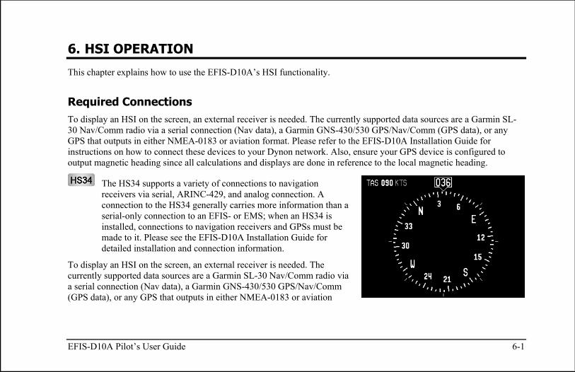
Required Connections To display an HSI on the screen, an external receiver is needed. The currently supported data sources are a Garmin SL-30 Nav/Comm radio via a serial connection (Nav data), a Garmin GNS-430/530 GPS/Nav/Comm (GPS data), or any GPS that outputs in either NMEA-0183 or aviation format. Please refer to the EFIS-D10A Installation Guide for instructions on how to connect these devices to your Dynon network. Also, ensure your GPS device is configured to output magnetic heading since all calculations and displays are done in reference to the local magnetic heading.
The HS34 supports a variety of connections to navigation receivers via serial, ARINC-429, and analog connection. A connection to the HS34 generally carries more information than a serial-only connection to an EFIS- or EMS; when an HS34 is installed, connections to navigation receivers and GPSs must be made to it. Please see the EFIS-D10A Installation Guide for detailed installation and connection information.
To display an HSI on the screen, an external receiver is needed. The currently supported data sources are a Garmin SL-30 Nav/Comm radio via a serial connection (Nav data), a Garmin GNS-430/530 GPS/Nav/Comm (GPS data), or any GPS that outputs in either NMEA-0183 or aviation
EFIS-D10A Pilot’s User Guide 6-1

HSI Operation
6-2 EFIS-D10A Pilot’s User Guide
format. Please refer to the EFIS-D10A Installation Guide for instructions on how to connect these devices to your Dynon network. Also ensure your GPS device is configured to output magnetic headings since all calculations and displays are done in reference to the local magnetic heading.
Accessing the HSI/DG Page The HSI is displayed as a full-screen page on your EFIS-D10A. If the HSI is defined as part of a screen setup in your rotation, display the HSI page using either of the screen rotation hotkeys (buttons 1 and 6) until the appropriate page is displayed. If the HSI screen is not in your rotation, you can access the HSI by holding down the right button and navigating to the HSI screen. See page 3-2 for more information on screen configuration.
All HSI screens in a DSAB network share their configuration and are identical to one another at all times. Changing the source of information on one HSI page affects all units, as does changing scaling, bugs, or bearing pointers. It is not possible to show a NAV radio on one screen and a GPS on another screen.
HSI Display Basics There are three possible sources of information on the HSI page: GPS, NAV, and internal EFIS data. It is important to know what equipment is sourcing your data, so most displayed data is color coded so that it is easy to identify the source of the data. Data that is sourced from a GPS unit is color coded in magenta, and includes course direction, course deviation, vertical guidance, ground track, ground speed, altitude, distance to waypoint, and other data. Data that comes from a navigation radio (VOR / LOC) is green in color and includes the course, course deviation, glideslope, nav mode, to/from, OBS setting, tuned frequency, station identifier, and more. The final data source is information that comes from the EFIS itself and is color coded in white. The EFIS-sourced data includes magnetic heading, true airspeed, winds, and various other data points. Below are some of the basics

HSI Operation
EFIS-D10A Pilot’s User Guide 6-3
1. Mode flag. This indicator, located at the upper left of the HSI page, tells you what mode the radio and display are in. There are five options for this indicator.
a. "GPS" in magenta text: This indicates the data source for the overlay is a GPS stream.
b. "NAV" in black letters on a green background. This indicates that the system is in NAV mode, but there is no active VOR or localizer tuned. This is the same as a cross hatch indicator in the TO/FROM flag on a mechanical CDI. Do not rely on any indications on this page except for the DG and TAS when this flag is set.
c. "VOR" in green text. This means the radio is tuned to a standard VOR station and is giving a valid TO or FROM indication.
d. "LOC" in green text. This indication means that the radio is tuned to a localizer. The glideslope scale is visible as well, but may be flagged invalid.
e. "BC" in yellow text. This indication means that the radio is tuned to a localizer and is in back course mode. The glideslope scale is visible as well, but may be flagged invalid. Note: when flying a back course on an HSI, no reversal is needed since the CDI indicator spins with the DG. If the course is set to the runway heading of the ILS, when flying the back course, the CDI is flipped 180 degrees and indicates properly with no reversal needed. If you put the SL-30 into back course mode, you need to set the course to the heading of the back course runway. Setting the course to the heading of the primary ILS runway causes the CDI needle to be reversed.
2. Digital heading indicator. The number in this box is the current magnetic heading of the aircraft in degrees from 001 to 360. The accuracy of this data depends on the accuracy of the heading calibration for your EFIS-D10A.
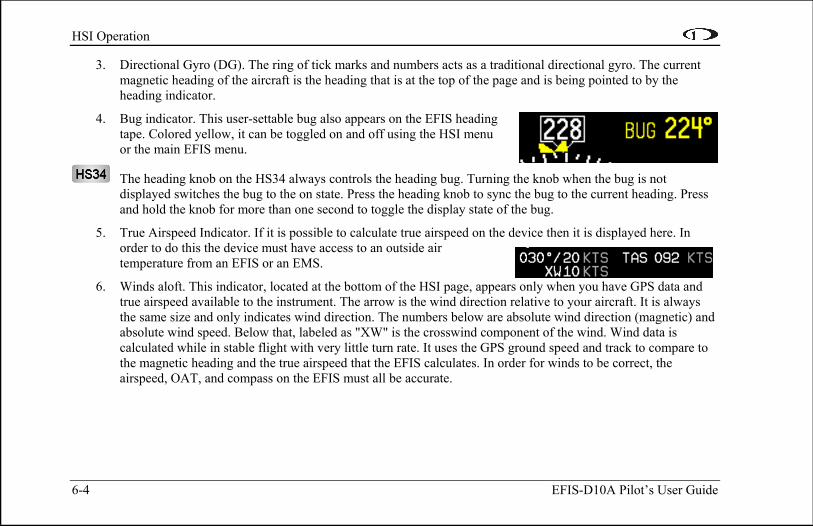
HSI Operation
6-4 EFIS-D10A Pilot’s User Guide
3. Directional Gyro (DG). The ring of tick marks and numbers acts as a traditional directional gyro. The current magnetic heading of the aircraft is the heading that is at the top of the page and is being pointed to by the heading indicator.
4. Bug indicator. This user-settable bug also appears on the EFIS heading tape. Colored yellow, it can be toggled on and off using the HSI menu or the main EFIS menu.
The heading knob on the HS34 always controls the heading bug. Turning the knob when the bug is not displayed switches the bug to the on state. Press the heading knob to sync the bug to the current heading. Press and hold the knob for more than one second to toggle the display state of the bug.
5. True Airspeed Indicator. If it is possible to calculate true airspeed on the device then it is displayed here. In order to do this the device must have access to an outside air temperature from an EFIS or an EMS.
6. Winds aloft. This indicator, located at the bottom of the HSI page, appears only when you have GPS data and true airspeed available to the instrument. The arrow is the wind direction relative to your aircraft. It is always the same size and only indicates wind direction. The numbers below are absolute wind direction (magnetic) and absolute wind speed. Below that, labeled as "XW" is the crosswind component of the wind. Wind data is calculated while in stable flight with very little turn rate. It uses the GPS ground speed and track to compare to the magnetic heading and the true airspeed that the EFIS calculates. In order for winds to be correct, the airspeed, OAT, and compass on the EFIS must all be accurate.

HSI Operation
EFIS-D10A Pilot’s User Guide 6-5
Navigation Radio Overlay The figure at right shows an HSI page with information sourced from a navigation radio. This data could be a VOR or a localizer. The various elements are described below.
1. Text displays. The text displays (located along the left side of the HSI Page) provide a variety of information. Displayed here is the course/OBS setting, the active frequency that the SL-30 is tuned to, the identifier for the tuned frequency, and the bearing to the active and secondary frequencies. When the data is not available or is not valid, the various data fields in this area are replaced by dashes.
2. Course indicator. The green course indicator (shown pointing to 273º at right) has an arrow at its end which points to the currently selected course (OBS) on your nav radio. This setting is also shown in the text area as "OBS." When tuned to a VOR, this is the radial that you wish to fly. When tuned to an ILS, this is set to the runway heading. In a situation with no winds, keeping the course indicator pointed straight up and in line with the heading pointer keeps the aircraft on course. This indicator is fixed to the rotation of the DG, so it is easy to see which way you must turn to get on course. The course indicator is only present when you are tuned to a VOR or a localizer. If the nav radio indicates that you are not currently tuned to an active frequency, this indicator is not displayed. The direction of this course is set externally using the knob that is on the SL-30 when in VOR mode. When in ILS mode, the SL-30 disables the OBS knob, and thus you must use the soft keys below the HSI in order to set the course.
When using the HS34 you can set the OBS using the course knob; the HS34 can communicate with the NAV radio instead of just receiving data from it, as with a standard serial connection. The HS34 sends the course

HSI Operation
6-6 EFIS-D10A Pilot’s User Guide
change to the NAV radio, just like a mechanical HSI or CDI does. In the case of the SL-30, either the OBS knob on the SL-30 or the HS34 may be used.
3. Course Deviation Indicator (CDI). When tuned to a VOR, the CDI indicates how far to the left or right of your selected radial you are. Full scale deviation indicates ten degrees of deviation from the radial that has been chosen as the course. When tuned to a localizer, full scale represents 2.5 degrees of deviation. When on course, the course indicator and the CDI make a solid line, making it easy to see when there is little error in your aircraft's position. Unlike a CDI indicator found in basic aircraft, the CDI needle on an HSI rotates with the DG and course indicator. By turning the aircraft towards the CDI needle you reduce your deviation.
4. To/From indicator. Because an HSI rotates the course line on top of the DG, the to/from indicator always points TO the physical VOR or localizer transmitter. If it is pointing the same direction as the arrow at the end of course line, then that is a "to" indication. If it is pointing the opposite direction of the arrow at the end of the course line, then that is a "from" indication. This data comes from the to/from flag indicator provided by your Nav radio. In the image above, the to/from indicator is showing a “from” indication.
5. Glideslope Indicator. This appears only when tuned to an ILS. It displays deviation as 0.5 degrees when deflected full scale. This does not have an indicator on it unless the glideslope is valid as defined by the glideslope flag.
6. Glideslope flag. This appears when the radio is tuned to a localizer and the glideslope is not valid. When this is active, there is no indicator mark on the GS scale.
7. Bearing To indicators. These arrows show you the bearing to the active and standby VORs. This is the direction that you would need to fly to go directly from where you are to the transmitter. When flying directly on course, your bearing and course lines overlap one

HSI Operation
EFIS-D10A Pilot’s User Guide 6-7
another. The primary bearing indicator is depicted by a yellow diamond and the standby indicator is depicted by an orange circle. These elements only appear when the active and/or standby VORs are tuned to an active frequency. A numerical display of your primary (labeled NAV) and standby (labeled SBY) bearings and a reminder of which symbol represents each bearing is in the text area of the page.
The HS34 adds the possibility of having many more bearing sources in the system, so the behavior of the BRG SRC button is dependent on how many devices you have connected. When you press this button, if you have only one possible bearing source, the bearing source toggles on and off. If you have two or more bearing sources, pressing the BRG SRC button highlights the first bearing source. Turning the value knob allows you to choose your bearing source from all options. Pressing the bearing source again chooses the second bearing source. If you wait more than 5 seconds without adjusting anything or pressing any buttons, the selection self-clears.
GPS Overlay The figure at right shows an HSI page with information sourced from a GPS receiver while the GPS has an active flight plan between two points. The various elements are described below.
1. Text displays. In this area a variety of information is displayed in text format. Displayed here is the ground track (TRK), the course (CRS), ground speed (SPD), distance to next waypoint (DTW), and up to two bearing pointer selections.
2. Course indicator. The course indicator points in the direction of the course that the GPS is reporting*. This is usually the direction of the line between the start and end waypoints. This setting is also shown in

HSI Operation
6-8 EFIS-D10A Pilot’s User Guide
the text area as "CRS." In a situation with no winds, keeping the course indicator pointed straight up and in line with the heading pointer keeps the aircraft on course. This indicator is fixed to the rotation of the DG, so it is easy to see which way you must turn to get on course. The course indicator is only present when you have an active flight plan in your GPS and are navigating to a point. *Some GPS units do not report course direction. In this case, a COURSE menu item is made available in the HSI menu to manually set it.
3. Course Deviation Indicator (CDI). When a flight plan is active in the GPS, the CDI indicates how far to the left or right of your selected ground course you are (CDI in large oval at right). Depending on the scale that you are in, each dot indicates 0.06 n.m. (Approach), 0.2 n.m. (Terminal), or 1.0 n.m. (Enroute). When on course, the course indicator and the CDI make a solid line, making it easy to see when there is little error in your aircraft's position. Unlike a CDI indicator found in basic aircraft, the CDI needle on an HSI rotates with the DG and course indicator. By turning the aircraft towards the CDI needle so the CDI needle is "on top" of the course line you reduce your deviation.
4. To indicator. There is no "from" indication with GPS data, since the GPS is the source of the course line. This arrow always points the same way as the course line, as indicated in the small oval at right.
5. Vertical Guidance Indicator. When connected to a Garmin 396/496 the glideslope indicator mimics the GPS’s vertical guidance display. This appears only when a VNAV profile is active on the GPS.
When the HS34 is connected to a WAAS-enabled GPS that can provide vertical guidance, this vertical guidance is displayed as specified by your GPS user manual.
6. Bearing to waypoint (BTW) indicator. This thin yellow diamond shows the bearing to the destination waypoint. The diamond points in the direction you would need to fly from your present location to the waypoint. When

HSI Operation
EFIS-D10A Pilot’s User Guide 6-9
flying directly on course, your BTW and course lines overlap one another. The text area of the page contains a numerical display of this bearing and a diamond icon to signify its symbol on the display.
The HS34 adds the possibility of having many more bearing sources in the system, so the behavior of the BRG SRC button is dependent on how many devices you have connected. When you press this button, if you have only one possible bearing source, the bearing source toggles on and off. If you have two or more bearing sources, pressing the BRG SRC button highlights the first bearing source. Turning the value knob allows you to choose your bearing source from all options. Pressing the bearing source again chooses the second bearing source. If you wait more than 5 seconds without adjusting anything or pressing any buttons, the selection self-clears.
7. Scale indicator. This shows you what scale the CDI is using. Since serial GPS streams do not indicate the correct scaling mode, this must be configured manually with the "scale" button under the HSI menu. The three options are "E" for enroute (5 n.m. full scale), "T" for terminal (1 n.m. full scale), and "A" for approach (0.3 n.m. full scale). The current scale name and full scale range is indicated on the screen.
When the HS34 is hooked to a GPS unit via ARINC-429, the system can read the scaling from the ARINC-429 connection. When connected this way, the scaling auto-updates and follows the GPS. The indication on the screen for mode and range should match the mode and range of the GPS at all times. When in this mode, the range is not limited to just 5/1/0.3nm, as the GPS may slide between scales, so it would not be unexpected to see a number such as 0.8 on the screen. Because of this behavior, on the final phases of an approach, a GPS hooked to the HS34 via ARINC-429 acts much like a VOR receiver would with the CDI acting as angular deflection, not linear distance. There are still only three master modes of Enroute, Terminal, and Approach, which are annunciated on the screen.
8. Track indicator. This indicates your direction over the ground as reported by the GPS. This is different than your magnetic heading when there are crosswinds present. Since this is your actual
HSI Operation
6-10 EFIS-D10A Pilot’s User Guide
ground track, keeping this directly above your course pointer (when the CDI is centered) keeps you on course, even if your magnetic heading is different. As long as a valid GPS source is detected by the system, the ground track indicator can be displayed. This is not dependent on the currently set nav source.
HSI Menu Structure NAVSRC - This is used to choose what navigation source is displayed on the HSI page and the EFIS main page. Pressing this button steps through the three options: DG, NAV, and GPS. This button cycles through only the overlays that are available in the system; NAV or GPS pages are not available if these data sources are not hooked up.
The NAV SRC button on the HS34 performs the same function as this NAVSRC menu button, but may cycle through NAV1, NAV2, etc, if you have multiple units connected. The NAV SRC button on the HS34 only works when the HSI page is displayed on the DSAB master. If it is pressed when no HSI is displayed, it has no effect.
BUG - This is the same menu as EFIS > BUGS > HDG. This menu allows you to adjust and toggle a heading bug that appears on the DG display as well as the EFIS heading tape.
The heading bug can be adjusted at any time by rotating the HS34’s HEADING knob. If the bug is currently toggled off, rotating the HEADING knob causes the bug to be displayed on the HSI display. To sync the bug to your current heading, press the heading knob briefly. To toggle the heading bug on or off, push and hold the heading knob for more than 1 second.
COURSE (Nav mode, Localizer active) - This is used to set the OBS/course. The SL-30 does not allow you adjust the OBS when tuned to a localizer so this must be done locally on the instrument.

HSI Operation
EFIS-D10A Pilot’s User Guide 6-11
When you have an HS34 with any NAV instrument, the course knob on the HS34 adjusts the course/OBS. You can adjust the course when in NAV or localizer mode. When using a GPS such as the 430/530, that allows an external course command to control the instrument, this course adjustment also works. If the GPS or NAV device is in a mode where it is ignoring course commands, turning the course knob results in no change on the screen. This is true when you are in most GPS modes.
SCALE (GPS mode) - This is used to cycle through the three GPS scale modes.
The scale button only exists if the source you are connected to is not providing scale information.


7. ALERTS
Alarm Indicators Any time a built-in or preconfigured alarm set point is exceeded, you are alerted to the fact via the alarm bar and menu at the bottom of the screen.
When an alarm is triggered, the following things occur:
• A red alarm bar appears at the bottom of the screen with a message identifying the out of range measurement • Below the alarm bar, the alarm menu gives you options for what to do next. See the following subsections for more
information
Note that alarms may not be acknowledged during the initial two seconds of the first alarm.
In an alarm condition, the EFIS-D10A does not alert you audibly. The audio out connection on the EFIS-D10A is for AOA alerts only. If you have a Dynon EMS-based product installed, connected to both your EFIS-D10A and cockpit audio system, EMS-based alarms will still sound an audible alarm.
EFIS-D10A Pilot’s User Guide 7-1
If your EFIS-D10A is networked to other Dynon products via DSAB, alarms sourced from those products will appear on your EFIS-D10A as well. Alert messages sourced from your EFIS-D10A are preceded by the label “THIS.” Alert messages sourced from another Dynon product are preceded by the label “DSAB.” Pressing SILNCE or ACK on any unit in the system silences or confirms the alarm on all units in the system. See the EFIS-D10A Installation Guide for more information.
Alerts
7-2 EFIS-D10A Pilot’s User Guide
SHOW PAGE If the alarming measurement is not displayed on your current screen, or is available on a page which displays it better, a SHOW [PAGE] button is included in the alarm menu. [PAGE] is replaced with the name of the actual page that is displayed when you press the button. Press this button to display the page where the alarming measurement is best displayed. From there, you may press GO BACK to return to your original screen, leaving the alarm indications active, or press ACK to remove the alarm indications and return to your original screen.
ALARM ACKNOWLEDGEMENT To acknowledge the alarm, press the ACK button. The ACK button has a number next to it indicating the number of currently posted alarms. If this number is higher than 1, after you press ACK, you will see the alarm text for the next posted alarm. Pressing ACK does the following:
• Removes the alarm bar and alarm menu (if no other alarms are stacked up), and brings up the previous menu. • Stops the blinking of the relevant display • Returns the display to the screen configuration displayed before the alarm occurred (if you pressed SHOW [PAGE])
The tic and numeric value remain red until the condition no longer exists. The alarm automatically rearms whenever the alarm condition is removed.
When acknowledging a voice alert from the HS34, the full text of the current alarm is read before it is silenced; no other queued alarms will be announced after that.
Multiple Alarms Any time multiple alarms occur in quick succession, they are handled in the following way:

Alerts
EFIS-D10A Pilot’s User Guide 7-3
1. Each numeric value and gauge posts its alarm by turning red, blinking, bringing up the alarm bar, and triggering the external light and audio alert.
2. Alarm messages in the alarm bar are stacked into memory and presented in the order in which they occurred, unless a higher priority alarm occurs. Removal of the Alarm Bar requires separate pilot acknowledgement of each alarm.
3. The ACK button displays a number indicating the number of stacked up alarms. 4. When the last alarm is acknowledged, the Alarm Bar and Alarm Menu are removed from the screen. 5. Once the top alarm is acknowledged, the next alarm in the stack is shown.
DSAB Alerts When multiple Dynon Avionics instruments are networked together via DSAB, there are a few error messages
designed to warn you of failures or reduced functionality.
NETWORK CONFIGURATION ERROR: This error can only occur within a short period of time after the system is turned on. This error indicates that a unit that was expected to be on the DSAB network was not found. For example, if – in a system consisting of a FlightDEK-D180, EFIS-D100, and an HS34 – all three units are not present, this error appears. This error is displayed when any part of the system is not working, including backup EDCs or OATs.
If this error is unexpected, check all Dynon equipment for proper function, and cycle the power to all units. Additional information on the missing unit can be found on the network status page under SETUP > DSAB > STATUS. If a unit is purposefully removed from the system, refer to the EFIS-D10A Installation Guide for instructions on reconfiguring the network.
NETWORK CONNECTION LOST: This error means that all network communication has stopped. In this event, no instruments share data or settings until the cause of the communication problem is resolved and all units are power cycled. Individual units that are powered on and functioning continue to function using their internally-derived data.

Alerts
7-4 EFIS-D10A Pilot’s User Guide
<INSTRUMENT FUNCTION> CONNECTION LOST: This indicates that the network is still functioning, but a device in charge of providing a specific role on the network has stopped communicating. This means that other screens in the system can no longer display information related to that function. If you receive an “EMS LOST” message on an EFIS product, all EFIS-related pages still function, but all EMS pages are blank. This failure can warn about subsystem failures, such as an EDC or an OAT. In these cases, the device falls back to a local OAT or EDC, if it is available. The <INSTRUMENT FUNCTION> LOST message is preceded by “THIS:” or “DSAB:” on each connected display instrument. If the label is “THIS:” then the screen with this label is the source of the failure. If the message begins with “DSAB:” than the message indicates a failure on another device.
This message relates to the function on the network that goes missing, not the specific name of the unit that fails. A FlightDEK-D180 can be a provider of EFIS and/or EMS data, so the failure of a D180 would present as "EMS" and/or "EFIS" lost, depending on its function in the network.
If the HS34 is not communicating on DSAB properly, both the NAV and GPS lights are illuminated. During normal system operation both lights will never be illuminated simultaneously; dual illumination indicates a communication failure. Additionally, if the DSAB network fails in flight “DSAB ERROR” will be annunciated via HS34’s the audio output.

8. APPENDIX
This appendix contains information not covered in the main section of the manual. This section contains reference tools such as a detailed description of the serial data format output by the EFIS-D10A, a specifications sheet, and a troubleshooting guide. This section also contains details regarding EFIS-D10A servicing.
Appendix A: Serial Data Output The EFIS-D10A has one RS232 serial port which outputs EFIS data. Technical information on the installation and connection to these serial ports can be found in the EFIS-D10A Installation Guide. To log EFIS data, you must connect the serial port to a PC. This serial data can be logged using any standard serial terminal program such as HyperTerminal®. It can then be parsed into its respective columns by many spreadsheet programs including Microsoft Excel®. All numbers are output in decimal and are standard ASCII. To view the data using a terminal program, the following settings should be used for both serial ports: Baud rate: 115200 Data: 8 bit Parity: none Stop: 1 bit Flow control: none
EFIS-D10A Pilot’s User Guide 8-1
The following section details the format used for EFIS data output.
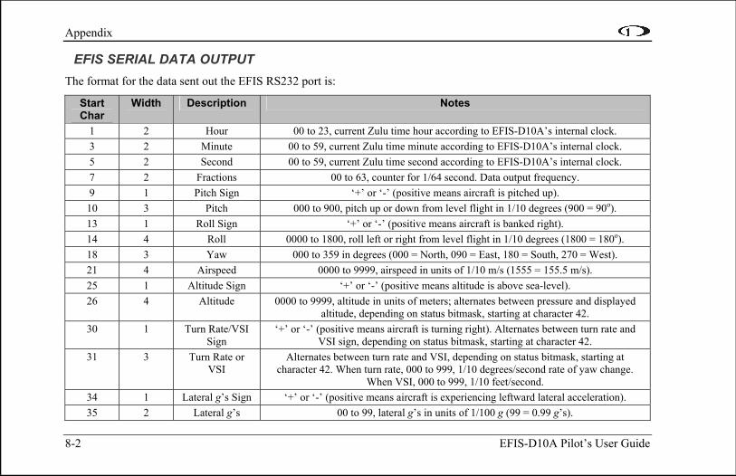
Appendix
8-2 EFIS-D10A Pilot’s User Guide
EFIS SERIAL DATA OUTPUT The format for the data sent out the EFIS RS232 port is:
Start Char
Width Description Notes
1 2 Hour 00 to 23, current Zulu time hour according to EFIS-D10A’s internal clock. 3 2 Minute 00 to 59, current Zulu time minute according to EFIS-D10A’s internal clock. 5 2 Second 00 to 59, current Zulu time second according to EFIS-D10A’s internal clock. 7 2 Fractions 00 to 63, counter for 1/64 second. Data output frequency. 9 1 Pitch Sign ‘+’ or ‘-’ (positive means aircraft is pitched up). 10 3 Pitch 000 to 900, pitch up or down from level flight in 1/10 degrees (900 = 90o). 13 1 Roll Sign ‘+’ or ‘-’ (positive means aircraft is banked right). 14 4 Roll 0000 to 1800, roll left or right from level flight in 1/10 degrees (1800 = 180o). 18 3 Yaw 000 to 359 in degrees (000 = North, 090 = East, 180 = South, 270 = West). 21 4 Airspeed 0000 to 9999, airspeed in units of 1/10 m/s (1555 = 155.5 m/s). 25 1 Altitude Sign ‘+’ or ‘-’ (positive means altitude is above sea-level). 26 4 Altitude 0000 to 9999, altitude in units of meters; alternates between pressure and displayed
altitude, depending on status bitmask, starting at character 42. 30 1 Turn Rate/VSI
Sign ‘+’ or ‘-’ (positive means aircraft is turning right). Alternates between turn rate and
VSI sign, depending on status bitmask, starting at character 42. 31 3 Turn Rate or
VSI Alternates between turn rate and VSI, depending on status bitmask, starting at
character 42. When turn rate, 000 to 999, 1/10 degrees/second rate of yaw change. When VSI, 000 to 999, 1/10 feet/second.
34 1 Lateral g’s Sign ‘+’ or ‘-’ (positive means aircraft is experiencing leftward lateral acceleration). 35 2 Lateral g’s 00 to 99, lateral g’s in units of 1/100 g (99 = 0.99 g’s).
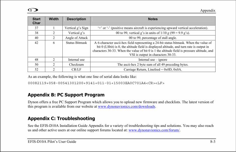
Appendix
EFIS-D10A Pilot’s User Guide 8-3
Start Char
Width Description Notes
37 1 Vertical g’s Sign ‘+’ or ‘-’ (positive means aircraft is experiencing upward vertical acceleration). 38 2 Vertical g’s 00 to 99, vertical g’s in units of 1/10 g (99 = 9.9 g’s). 40 2 Angle of Attack 00 to 99, percentage of stall angle. 42 6 Status Bitmask A 6-character ascii-hex field representing a 24-bit status bitmask. When the value of
bit 0 (LSbit) is 0, the altitude field is displayed altitude, and turn rate is output in characters 30-33. When the value of bit 0 is 1 the altitude field is pressure altitude, and
VSI is output in characters 30-33. 48 2 Internal use Internal use – ignore 50 2 Checksum The ascii-hex 2 byte sum of all 49 preceding bytes. 52 2 CR/LF Carriage Return, Linefeed = 0x0D, 0x0A.
As an example, the following is what one line of serial data looks like: 00082119+058-00541301200+9141+011-01+15003EA0C701A4<CR><LF>
Appendix B: PC Support Program Dynon offers a free PC Support Program which allows you to upload new firmware and checklists. The latest version of this program is available from our website at www.dynonavionics.com/downloads.
Appendix C: Troubleshooting See the EFIS-D10A Installation Guide Appendix for a variety of troubleshooting tips and solutions. You may also reach us and other active users at our online support forums located at: www.dynonavionics.com/forum/.

Appendix
8-4 EFIS-D10A Pilot’s User Guide
Should you experience difficulty with your product that is not solved by reading the troubleshooting section or by posting on our forum, please call us at (425) 402-0433 or email us at [email protected]. Be sure to have the EFIS-D10A’s firmware version number ready when you contact us. To locate your product’s firmware version, refer to the Check firmware version section on page 5-10.
See the following list of alert messages displayed by the EFIS-D10A. The list provides information about what they mean and what to do about them.
ALERT MESSAGES The following table describes the error/warning messages that the EFIS-D10A could display. The meaning of the message is given here as well as information about what conditions clear the alert.
Alert Message Meaning End condition POWER DOWN IN 30 SECS.
This alert appears when master switch power has been switched off but either the internal or the external emergency batteries are still connected. If no button is pressed within 30 seconds of when the alert appears, the unit turns off. The voltmeter also appears to show you the currently measured battery voltages prior to the unit turning off.
If any button is pressed, the alert disappears and the unit stays on. This causes the unit to continue full operation on battery power. The internal battery is rated for a minimum of 2 hours when fully charged. If no button is pressed within 30 seconds, the unit enters an extremely low-power mode.
INTERNAL BATTERY LOW
This alert is displayed when operating the unit solely off the internal backup battery and its voltage drops below 13V. Additionally, the voltmeter is displayed onscreen. When you see this alert, it is advisable that you turn the unit off by pressing and holding the leftmost button when no menus are displayed.
The alert is cleared when you press any button; however, it is advised that you do not ignore this alert, as it appears when the unit’s internal battery has very little life left. This alert is also cleared upon the application of either the external backup battery or master switch power. At that point, the battery begins charging off the external power.

Appendix
EFIS-D10A Pilot’s User Guide 8-5
Alert Message Meaning End condition HORIZON RECOVERING…
This alert is displayed anytime the unit is rotated at a rate faster than 150 degrees/second. Rotating the unit faster than this threshold overloads the sensors, leading to a potentially erroneous display. When this alert is displayed, the horizon indication turns grey and black to indicate that the artificial horizon is not currently a trusted source. This alert can only be triggered when airspeed is non-zero; using the EFIS-D10A on the bench will not trigger this alert.
Pressing the ACK button removes the text of the alert. However, the horizon indication remains grey/black until the unit has resumed normal operation. Once the unit detects relatively coordinated flight, it usually recovers within 5 seconds.
HOLD TO POWER DOWN
This alert appears when you have pressed the POWER button in Main Menu 1. If the button is held for 2 seconds, the unit turns off.
Releasing the POWER button causes the alert to disappear, allowing the unit to continue normal operation.
TEMPERATURE OUT OF SPEC
This alert appears when the ambient temperature sensed by the unit is below -30ºC or above 50ºC. The sensors in the unit have a certain temperature range within which they are specified to operate normally. If they operate outside this temperature range, the attitude result can be compromised. When the temperature is too high or low, the horizon indication turns to grey/black to indicate the potential unreliability of the sensors.
The text portion of the alert disappears when you press any of the buttons. However, the horizon will not display blue/brown until the unit senses temperature within its specified range. If ambient temperature is above 50ºC, the unit always displays the horizon as grey/black. However, if ambient is below -30ºC, it is possible that the unit can heat itself up enough to operate normally.
TIMER EXPIRED This alert appears when you have a down timer enabled and it has reached 0. When this occurs, the up timer menu displays and the timer display flashes.
Pressing the ACK button removes the alert and stops the timer’s flashing. However, you must press STOP in the Up Timer menu to stop the up timer. This allows you to see how much time has elapsed since the down timer has expired.

Appendix
8-6 EFIS-D10A Pilot’s User Guide
Alert Message Meaning End condition OAT SENSOR NOT DETECTED
This alert appears when the EFIS-D10A has an OAT connected and then loses that connection for some reason. Either the EDC-D10A has become disconnected, or the OAT sensor itself has become disconnected from the EDC-D10A.
Double-check your wiring between the EFIS-D10A and the EDC-D10A as well as that of the OAT sensor.
REMOTE COMPASS NOT DETECTED
The EFIS-D10A is unable communicate with the EDC-D10A. If you have an OAT connected to your EDC-D10A, it will not be displayed either.
Ensure that you a) have an EDC-D10A installed and b) have verified that the wiring to the EDC-D10A is correct. Please see the EFIS-D10A Installation Guide for more information on verifying the installation of the EDC-D10A. This error also can appear if you have updated the firmware in your EFIS-D10A while the remote compass was not connected. If this is the case, try uploading the new firmware again with the EDC-D10A connected. Attempt the connection within the first few seconds of operation. Note that the EFIS-D10A does not have internal magnetic sensors and thus requires the EDC-D10A be connected.
TEMPERATURE UNSTABLE
When the unit is turned on after having been off for a long period, its internal temperature rises above ambient at a fast rate. This fast change in temperature can sometimes reduce the reliability of the output of the sensors. Therefore, this alert is displayed and the horizon indication is changed from blue/brown to grey/black.
The alert is cleared when you press any of the buttons. The screen remains grey and black until the temperature within the unit has stabilized. This temperature instability should last no longer than 2 minutes. For this reason, it is a good idea to turn the unit on before you run through any of the preflight procedures, so that it will be ready by the time you are ready to fly.

Appendix
EFIS-D10A Pilot’s User Guide 8-7
Alert Message Meaning End condition INTERNAL ERROR SERVICE UNIT
This error can occur for a few reasons, including an aborted upload.
When this error appears, it may be possible to recover your unit in the field. The best way of ensuring this is to call Dynon Avionics immediately. However, there is a good possibility that the unit will have to be returned for service.

Appendix
8-8 EFIS-D10A Pilot’s User Guide
Appendix D: EFIS-D10A Specifications
Mechanical
Mounting: Fits into standard 3 1/8” panel hole Optional flush mount bracket available
Weight: 1 lb. 9 oz. (700 g) 1 lb. 15 oz. (880 g) with internal battery
Operating Temperature -22° to 122° F (-30° to 50° C)
Power Voltage: 10 - 30 VdcPower: 8 watts typical; 13 watts maximum
Connections Wiring: D-25 male
Screen
Type: AMLCD, TFT (Thin Film Transistor)Backlight: 450 nits Size: 4.0” diagonal (101.6 mm) Resolution: 320 x 240 color pixels
Inputs/Outputs
1 - Audio Alarm 1 - RS-232 bidirectional PC communication 1 - RS-232 data input (GPS, SL30, etc.) 1 - Dynon Smart Avionics Bus (DSAB)