eg 201 400-01 - v01.01.01 - hybrid fiber coax (hfc) … 4 eg 201 400-1 v1.1.1 (1999-02) 7.5.1...
TRANSCRIPT

EG 201 400-1 V1.1.1 (1999-02)ETSI Guide
Hybrid Fiber Coax (HFC) access networks;Part 1: Interworking with PSTN, N-ISDN,
Internet and digital mobile networks

ETSI
EG 201 400-1 V1.1.1 (1999-02)2
ReferenceDEG/NA-080201 (cyo90icq.PDF)
Keywordsaccess, digital, internet, interworking, ISDN,
mobile, network, PSTN
ETSI
Postal addressF-06921 Sophia Antipolis Cedex - FRANCE
Office address650 Route des Lucioles - Sophia Antipolis
Valbonne - FRANCETel.: +33 4 92 94 42 00 Fax: +33 4 93 65 47 16
Siret N° 348 623 562 00017 - NAF 742 CAssociation à but non lucratif enregistrée à laSous-Préfecture de Grasse (06) N° 7803/88
Individual copies of this ETSI deliverablecan be downloaded from
http://www.etsi.orgIf you find errors in the present document, send your
comment to: [email protected]
Copyright Notification
No part may be reproduced except as authorized by written permission.The copyright and the foregoing restriction extend to reproduction in all media.
© European Telecommunications Standards Institute 1999.All rights reserved.

ETSI
EG 201 400-1 V1.1.1 (1999-02)3
Contents
Intellectual Property Rights................................................................................................................................5
Foreword ............................................................................................................................................................5
Introduction ........................................................................................................................................................5
1 Scope........................................................................................................................................................6
2 References................................................................................................................................................6
3 Definitions, symbols and abbreviations...................................................................................................93.1 Definitions ......................................................................................................................................................... 93.2 Symbols ........................................................................................................................................................... 103.3 Abbreviations................................................................................................................................................... 10
4 Service Requirements ............................................................................................................................11
5 Functional requirements.........................................................................................................................11
6 Reference Configuration and Reference Points.....................................................................................136.1 The HFC access network general architecture and boundaries........................................................................ 136.2 Digital section for HFC access network........................................................................................................... 146.3 General reference configuration for HFC Access Networks............................................................................ 156.3.1 User Port Function ..................................................................................................................................... 156.3.2 Service Port Function................................................................................................................................. 166.3.3 Core Function............................................................................................................................................. 166.3.4 HFC User Interface Function ..................................................................................................................... 166.3.5 HFC Access Node Function ....................................................................................................................... 176.3.6 HFC Transport Network Function.............................................................................................................. 176.3.7 AN System Management Function............................................................................................................. 176.4 HFC Access Network configuration for the considered networks ................................................................... 176.5 Reference Points .............................................................................................................................................. 186.5.1 Reference points at the user interface side ................................................................................................. 186.5.2 Reference points at the network interface side ........................................................................................... 19
7 User Interfaces .......................................................................................................................................197.1 Broadcast UNI ................................................................................................................................................. 197.1.1 Analogue Broadcast UNI ........................................................................................................................... 197.1.1.1 Interface references............................................................................................................................... 207.1.1.2 Protocol stack reference........................................................................................................................ 207.1.2 Digital Broadcast UNI................................................................................................................................ 217.1.2.1 Interface references............................................................................................................................... 217.1.2.2 Protocol stack and peer communication stack reference ...................................................................... 217.2 PSTN UNI ....................................................................................................................................................... 227.2.1 Interface references .................................................................................................................................... 237.2.2 User Interface functions - POTS Cable Network Termination................................................................... 237.2.3 Protocol stack and peer communication stack reference configuration...................................................... 237.3 N-ISDN UNI.................................................................................................................................................... 247.3.1 Interface references .................................................................................................................................... 257.3.1.1 Basic access.......................................................................................................................................... 257.3.1.2 Primary access ...................................................................................................................................... 257.3.2 User Interface functions - N-ISDN Cable Network Termination ...............................................................257.3.3 Protocol stack and peer communication stack reference ............................................................................ 267.4 Internet Terminal UNI ..................................................................................................................................... 277.4.1 Interface references .................................................................................................................................... 287.4.2 User interface functions - IP Cable Network Termination ......................................................................... 287.4.2.1 Definition.............................................................................................................................................. 287.4.2.2 Functions and Technology.................................................................................................................... 287.4.3 Protocol stack and peer communication stack reference ............................................................................ 297.5 Leased Lines UNI ............................................................................................................................................ 30

ETSI
EG 201 400-1 V1.1.1 (1999-02)4
7.5.1 Interface references .................................................................................................................................... 317.5.2 User Interface functions - Leased Cable Network Termination ................................................................. 317.5.3 Protocol stack and peer communication stack reference ............................................................................ 31
8 Service Node Interfaces (SNI) (Access Node Interface) .......................................................................328.1 Broadcast Service ............................................................................................................................................ 328.2 PSTN Service specific Service node................................................................................................................ 328.2.1 Interface references .................................................................................................................................... 328.2.2 Network interface functions - PSTN Cable Line Termination ................................................................... 328.2.3 Protocol stack and peer communication stack reference configurations .................................................... 338.2.3.1 Protocol stacks...................................................................................................................................... 338.2.3.1.1 V5.1N interface............................................................................................................................... 338.2.3.1.2 V5.2N interface............................................................................................................................... 338.2.3.2 Protocol peer configurations................................................................................................................. 348.2.3.2.1 V5.1 interface.................................................................................................................................. 358.2.3.2.2 V5.2 interface.................................................................................................................................. 358.3 N-ISDN Service specific Service node............................................................................................................ 368.3.1 Interface references .................................................................................................................................... 368.3.2 Network interface functions - N-ISDN Cable Line Termination................................................................ 368.3.3 Protocol stack and peer communication stack reference configurations .................................................... 368.3.3.1 Protocol stacks...................................................................................................................................... 368.3.3.1.1 V5.1N interface............................................................................................................................... 368.3.3.1.2 V5.2N interface............................................................................................................................... 378.3.3.2 Protocol peer configurations................................................................................................................. 388.3.3.2.1 V5.1 interface.................................................................................................................................. 388.3.3.2.2 V5.2 interface.................................................................................................................................. 398.4 PSTN/N-ISDN Modular Service node............................................................................................................. 408.4.1 Interface references .................................................................................................................................... 408.4.2 Network interface functions - PSTN/N-ISDN Cable Line Termination..................................................... 408.4.3 Protocol stack and peer communication stack reference configurations .................................................... 408.4.3.1 Protocol stacks...................................................................................................................................... 408.4.3.1.1 V5.1N interface............................................................................................................................... 408.4.3.1.2 V5.2N interface............................................................................................................................... 418.4.3.2 Protocol peer configurations................................................................................................................. 428.4.3.2.1 V5.1 interface.................................................................................................................................. 428.4.3.2.2 V5.2 interface.................................................................................................................................. 438.5 Internet network............................................................................................................................................... 448.5.1 Interface references .................................................................................................................................... 448.5.2 Network interface functions - IP Cable Line Termination ......................................................................... 458.5.3 Protocol stack and peer communication stack reference ............................................................................ 458.5.3.1 Protocol stacks...................................................................................................................................... 458.5.3.2 Protocol peer communication ............................................................................................................... 468.6 Leased lines Specific Service network............................................................................................................. 468.6.1 Interface references .................................................................................................................................... 468.6.2 Network interface functions - Leased Line Cable Line Termination..........................................................468.6.3 Protocol stack and peer communication stack reference configurations .................................................... 46
9 Internal HFC Access Network Aspects..................................................................................................479.1 Interface references.......................................................................................................................................... 479.2 Internal HFC Access Network Structure.......................................................................................................... 479.3 HFC Access network channel structure and protocols..................................................................................... 48
Bibliography.....................................................................................................................................................49
History..............................................................................................................................................................50

ETSI
EG 201 400-1 V1.1.1 (1999-02)5
Intellectual Property RightsIPRs essential or potentially essential to the present document may have been declared to ETSI. The informationpertaining to these essential IPRs, if any, is publicly available for ETSI members and non-members, and can be foundin SR 000 314: "Intellectual Property Rights (IPRs); Essential, or potentially Essential, IPRs notified to ETSI in respectof ETSI standards", which is available free of charge from the ETSI Secretariat. Latest updates are available on theETSI Web server (http://www.etsi.org/ipr).
Pursuant to the ETSI IPR Policy, no investigation, including IPR searches, has been carried out by ETSI. No guaranteecan be given as to the existence of other IPRs not referenced in SR 000 314 (or the updates on the ETSI Web server)which are, or may be, or may become, essential to the present document.
ForewordThis ETSI Guide (EG) has been produced by ETSI Technical Committee Network Aspects (NA).
The present document is part 1 of a multi-part EG covering the Hybrid Fiber Coax (HFC) access networks, as identifiedbelow:
Part 1: "Interworking with PSTN, N-ISDN, Internet and digital mobile networks";
Part 2: "Interworking with B-ISDN Networks".
IntroductionCable TV networks are more and more used for other services than just broadcast service. At the user side serviceterminals other than TV and radio are attached. At the terminal side, the head end needs to interwork with a number ofservice related networks. The present document presents a number of different interfaces at the user side and thenetwork side and shows how the HFC access network interconnects them, both for user and signalling data.
ETSI
EG 201 400-1 V1.1.1 (1999-02)6
1 ScopeThe present document is focussed on the interworking between HFC networks and other networks. The different userequipment and the different user network interfaces to the access network have an influence on the interworking, and assuch, are also considered.
It may be the case that an independent cable operator operates an HFC access network that has no interface to aswitching network at all. In this case the HFC network is maybe not regarded as an access network, but nevertheless thenetwork may provide services to its customers beyond just Broadcast services. This case is beyond the scope of thepresent document, since no interworking is involved. If, on the other hand, an independent cable operator has interfacesto other switching networks, the contents of the present documents applies.
The present document considers the following public telecommunication networks:
- public switching telephone network;
- narrowband ISDN network;
- internet;
- leased lines networks.
Other public telecommunication networks will be considered in a later document.
Looking at broadcasting, it is considered as a service rather than as a network. The interfaces for broadcast services atthe HFC access network are however also considered. Analogue and digital broadcasting are handled separately.
2 ReferencesThe following documents contain provisions which, through reference in this text, constitute provisions of the presentdocument.
• References are either specific (identified by date of publication, edition number, version number, etc.) ornon-specific.
• For a specific reference, subsequent revisions do not apply.
• For a non-specific reference, the latest version applies.
• A non-specific reference to an ETS shall also be taken to refer to later versions published as an EN with the samenumber.
[1] ETR 306: "Transmission and multiplexing (TM); Access networks for residential customers".
[2] ITU-T Recommendation G.960 (1993): "Access digital section for ISDN basic rate access".
[3] ITU-T Recommendation G.962 (1993): "Access digital section for ISDN primary access at2 048 kbit/s".
[4] ITU-T Recommendation G.963 (1993): "Access digital section for ISDN primary access at1 544 kbit/s".
[5] ITU-T Recommendation G.964 (1994): "V-interfaces at the digital local exchange (LE) - V5.1interface (based on 2 048 kbit/s) for the support of access network (AN)".
[6] ITU-T Recommendation G.965 (1995): "V-interfaces at the digital local exchange (LE) - V5.2Interface (based on 2 048 kbit/s) for the support of access network (AN)".
[7] ISO/IEC 10038 (1993): "Information technology - Telecommunications and information exchangebetween systems - Local area networks - Media access control (MAC) bridges".

ETSI
EG 201 400-1 V1.1.1 (1999-02)7
[8] ISO/IEC 8802-2 (1997): "Information technology - Telecommunications and information exchangebetween systems - Local and metropolitan area networks- Specific requirements - Part 2: Logicallink control".
[9] ISO/IEC 8802-3 (1997): "Information technology - Telecommunications and information exchangebetween systems - Local and metropolitan area networks - Part 3: Carrier sense multiple accesswith collision detection (CSMA/CD) access method and physical layer specifications".
[10] ITU-T Recommendation G.902: "Framework Recommendation on functional access networks(AN) – Architecture and functions, access types, management and service node aspects".
[11] ETR 148: "Private Telecommunication Network (PTN); Integrated services architecture for highspeed private networks".
[12] ITU-T Recommendation N.51: "Definitions for application to international televisiontransmissions".
[13] ITU-T Recommendation I.112: "Vocabulary of terms for ISDNs".
[14] ITU-T Recommendation Q.512: "Digital exchange interfaces for subscriber access".
[15] ITU-T Recommendation Q.551: "Transmission characteristics of digital exchanges".
[16] ITU-T Recommendation Q.552: "Transmission characteristics at 2-wire analogue interfaces ofdigital exchanges".
[17] EN 50083-1: "Cabled distribution systems for television and sound signals - Part 1: Safetyrequirements".
[18] EN 50083-2: "Cabled distribution systems for television and sound signals - Part 2:Electromagnetic compatibility for equipment".
[19] EN 50083-3: "Cabled distribution systems for television and sound signals - Part 3: Active coaxialwideband distribution equipment".
[20] EN 50083-4: "Cabled distribution systems for television and sound signals - Part 4: Passive coaxialwideband distribution equipment".
[21] EN 50083-5: "Cabled distribution systems for television and sound signals - Part 5: Headendequipment".
[22] EN 50083-6: "Cabled distribution systems for television and sound signals - Part 6: Opticalequipment".
[23] EN 50083-7: "Cabled distribution systems for television and sound signals - Part 7: Systemperformance".
[24] ETS 300 429: "Digital Video Broadcasting (DVB); Framing structure, channel coding andmodulation for cable systems".
[25] ITU-T Recommendation J.83: "Digital multiprogramme systems for television, sound and dataservices for cable distribution".
[26] ITU-T Recommendation H.222.0: "Information technology - Generic coding of moving picturesand associated audio information: Systems".
[27] EN 300 001: "Attachments to the Public Switched Telephone Network (PSTN); General technicalrequirements for equipment connected to an analogue subscriber interface in the PSTN".
[28] ITU-T Recommendation I.411: "ISDN user-network interfaces - Reference configurations".
[29] ITU-T Recommendation Q.921: "ISDN user-network interface - Data link layer specification".
[30] ITU-T Recommendation Q.931: "ISDN user-network interface layer 3specification for basic callcontrol".

ETSI
EG 201 400-1 V1.1.1 (1999-02)8
[31] ITU-T Recommendation I.430: "Basic user-network interface - Layer 1 specification".
[32] ITU-T Recommendation I.431: "Primary rate user-network interface - Layer 1 specification".
[33] ETS 300 288: "Business TeleCommunications (BTC); 64 kbit/s digital unrestricted leased linewith octet integrity (D64U); Network interface presentation".
[34] ETS 300 418: "Business TeleCommunications (BTC); 2 048 kbit/s digital unstructured andstructured leased lines (D2048U and D2048S); Network interface presentation".
[35] ETS 300 448: "Business TeleCommunications (BTC); Ordinary quality voice bandwidth 2-wireanalogue leased line (A2O); Connection characteristics and network interface presentation".
[36] ETS 300 449: "Business TeleCommunications (BTC); Special quality voice bandwidth 2-wireanalogue leased line (A2S); Connection characteristics and network interface presentation".
[37] ETS 300 451: "Business Telecommunications (BTC); Ordinary quality voice bandwidth 4-wireanalogue leased line (A4O); Connection characteristics and network interface presentation".
[38] ETS 300 452: "Business Telecommunications (BTC); Special quality voice bandwidth 4-wireanalogue leased line (A4S); Connection characteristics and network interface presentation".
[39] ETS 300 766: "Business TeleCommunications (BTC); Multiple 64 kbit/s digital unrestricted leasedlines with octet integrity presented at a structured 2 048 kbit/s interface at either or both ends(D64M); Connection characteristics and network interface presentation".
[40] ETS 300 686: "Business TeleCommunications (BTC); 34 Mbit/s and 140 Mbit/s digital leasedlines (D34U, D34S, D140U and D140S); Network interface presentation".
[41] ETS 300 687: "Business TeleCommunications (BTC); 34 Mbit/s digital leased lines (D34U andD34S); Connection characteristics".
[42] ETS 300 688: "Business TeleCommunications (BTC); 140 Mbit/s digital leased lines (D140U andD140S); Connection characteristics".
[43] ETS 300 689: "Business TeleCommunications (BTC); 34 Mbit/s digital leased lines (D34U andD34S); Terminal equipment interface".
[44] ETS 300 690: "Business TeleCommunications (BTC); 140 Mbit/s digital leased lines (D140U andD140S); Terminal equipment interface".
[45] TBR 25: "Business TeleCommunications (BTC); 140 Mbit/s digital unstructured and structuredleased lines (D140U and D140S); Attachment requirements for terminal equipment interface".
[46] ETS 300 166: "Transmission and Multiplexing (TM); Physical and electrical characteristics ofhierarchical digital interfaces for equipment using the 2 048 kbit/s - based plesiochronous orsynchronous digital hierarchies".
[47] ETS 300 167: "Transmission and Multiplexing (TM); Functional characteristics of 2 048 kbit/sinterfaces".
[48] ETS 300 347: "V interfaces at the digital Local Exchange (LE); V5.2 interface for the support ofAccess Network (AN)".
[49] ETS 300 324: "V interfaces at the digital Local Exchange (LE); V5.1 interface for the support ofAccess Network (AN)".
[50] ITU-T Recommendation I.361: "B-ISDN ATM layer specification".
[51] ITU-T Recommendation I.363: "B-ISDN ATM Adaptation Layer specification".
[52] ITU-T Recommendation I.432: "B-ISDN User-Network Interface – Physical layer specification".
[53] ETS 300 800: "Digital Video Broadcasting (DVB); Interaction channel for Cable TV distributionsystems (CATV)".

ETSI
EG 201 400-1 V1.1.1 (1999-02)9
[54] ITU-T Recommendation J.112: "Vocabulary of terms for ISDNs".
[55] EN 50083-9: "Cable networks for television signals, sound and interactive services --Part 9:Interfaces for CATV/SMATV headends and similar equipment for DVB/MPEG-2 transportstreams".
[56] EN 50083-8: "Cabled networks for television signals, sound signals and interactive services --Part 8: Electromagnetic compatiblity for networks".
[57] EN 50083-10: "Cable networks for television signals, sound signals and interactive services --Part 10: System performance for return paths".
[58] IETF RFC 894 (1984): "A standard for the transmission of IP Datagrams over Ethernet Networks".
[59] IETF RFC 1042 (1988): "A standard for the Transmission of IP Datagrams over IEEE 802Networks".
3 Definitions, symbols and abbreviations
3.1 DefinitionsFor the purposes of the present document, the following definitions apply:
Access Network: an implementation, comprising those entities which provide the required transport bearer capabilitiesfor the provision of telecommunication services between a Service Node Interface and each of the associated user-network interfaces. An Access Network can be configured and managed through a Q3 interface. In principle there is norestriction on the types and the number of UNIs and SNIs which an Access Network may implement. The accessnetwork does not interpret (user) signalling.
Access Node (AN): a node providing access to the public network [ETR 148].
broadcast organisation: organisation which is concerned with sound and/or television broadcasting[ITU-T Recommendation N.51].
broadcast network: network providing sound and/or television signals to the user, either directly to the user or via anHFC access network.
CATV: used as a general term for "cable television" (historically used to indicate "Community Antenna TeleVision" - acentralized installation of television antennas that serves a community of users).
downstream direction: direction from the network towards the subscriber.
digital section: the whole of the means of digital transmission of a digital signal of specified rate between 2 consecutivereference points. The term should be qualified by the type of access supported, or by a prefix denoting the V interface atthe digital section bounderies.
Head End (HE): (definition in HFC access network context): equipment in an HFC access network, providinginterfaces between the HFC Access network and one or more other networks, and providing an RF communicationinterface with the user interface functions.
Hybrid Fiber/Coax (HFC) Access Network: a mixed fibre and coaxial network architecture using FDM transmissiontechnology based on RF frequencies, in which fibre links are used for the main distribution path, while coaxial links areused as the final link into the users' premises.
network interface functions: functions belonging to the Head End in a HFC access network.
service node: a network element that provides access to various switched and/or permanent telecommunication services.In case of switched services the SN is providing access call and connection control signalling, and access connectionand resource handling [ITU-T Recommendation G.902].

ETSI
EG 201 400-1 V1.1.1 (1999-02)10
service node interface: the interface between an Access Network and a Service Node. (ITU-T Recommendation G.902:The interface which provides customer access to a service node).
telecommunication network: a set of nodes and links that provides connections between 2 or more defined ports tofacilitate telecommunication between them [ITU-T Recommendation I.112].
upstream direction: direction from the subscriber towards the network.
User Interface Functions (UIF): functions in an access network, interacting with the user equipment, and providing aRF communication interface with the Head End it is connected to.
User Network Interface (UNI): the interface at which the user equipment is connected to the network.
3.2 SymbolsFor the purposes of the present document, the following symbols apply:
<R>C Reference point related to BroadCast service<R>I Reference point related to IP-based service<R>L Reference point related to Leased Line Service<R>N Reference point related to Narrowband ISDN service<R>T Reference point related to Telephony serviceC64 User channel of 64 kbit/sD16 Data channel of 16 kbit/sD64 Data channel of 64 kbit/sM Reference point at a service interface residing in a networkP Reference point at a service interface residing at the border of a networkQ3 Telecommunication Network Management InterfaceV5 Reference point at the SNI interface of an Access NetworkZ Reference point at the UNI interface of analogue telephony
3.3 AbbreviationsFor the purposes of the present document, the following abbreviations apply:
AN Access NetworkANI Access Network InterfaceCATV Community Antenna TeleVisionCF Core FunctionFDM Frequency Division MultiplexFE Function ElementHFC Hybrid Fiber CoaxHE Head EndLE Local ExchangePC Personal ComputerPRA Primary Rate AccessSN Service NodeSNI Service Node InterfaceSPF Service Port FunctionUIF User Interface FunctionsUPF User Port FunctionUNI User Network Interface

ETSI
EG 201 400-1 V1.1.1 (1999-02)11
4 Service RequirementsAn HFC Access Network may support a number of telecommunication services and telecommunication servicecomponents. The basic function of an HFC Access Network is that it uses RF frequencies for transportation of theinformation between the user side and the network side of the access network. As such, the information, including bothsignalling and user information, must be mapped in one way or another into the RF frequency spectrum and thetraditionally used frequency bands for Radio and Television. In addition to the downstream traffic, some upstreamtraffic may be required. Depending upon the type and bandwidth of the information, different solutions may be requiredfor different services to be supported.
HFC Access Networks may support (but are not required to support) the following Telecommunication services.
Supporting" means that the HFC AN does not provide the services itself, but provides the necessary channels, control,management and security functions for transporting the service information between Service Node and User equipment.
- Basic service: Radio and TV distribution service.
- Telephony service, its supplementary services, and all value added services such like telefax, DECT and voicedata modem services.
- Internet services: basic TCP/IP en UDP/IP communication and Internet services ftp, telnet, e-mail, usenet, wwwand gopher.
- Mobile services as defined for GSM, DCS 1800 and IMT-2000.
- B-ISDN services as defined in the F.700 and F.800 series.
- X25 based data services (PSPDN services).
The service component information types to be supported are:
- Sound: voice, music, etc.;
- Video: TV-programme, movie, etc.;
- Data: files, static pictures, text, low speed data, high speed data, real-time data, etc.
5 Functional requirementsThe fundamental principles of an access network and a HFC access network in particular are reflected by the followingfunctional requirements:
- an (HFC) AN is used in order to multiplex/demultiplex the signalling and data streams from UNIs in a costeffective manner and then to present this information stream to the SN in a manner such that the SN can determinethe source or sink UNI;
- concentration shall be supported across a V5 reference point as an option (although it shall always be possible toguarantee bandwidth for user ports who require such a facility such as the security services);
- the HFC AN does not interpret (user) signalling. Signalling for Telecommunication services should be handled asnear to transparently as possible. This means that the contents of signalling messages should not be checked unless itis unavoidable;
- the V5 reference point shall not be limited to a single physical interface (for redundancy and to allow more user portsto be connected);
- it is not a requirement for local switching to be carried out within the Access Network itself, either under SN controlor under local control;
- the responsibility for call control and associated connection control resides in the SN (i.e. the HFC AN may have noknowledge of ongoing services and the call state during normal operation);

ETSI
EG 201 400-1 V1.1.1 (1999-02)12
- tones and announcements should be generated in the service node(s) and not in the access networks themselves,except for local ringing and some kind of announcement when the user is not reachable from the service node (e.g.all access network lines busy);
- selection of the service provider by the HFC AN based on user signalling information shall not be possible, becausethis would require SN functionality in the HFC AN.
However, for ATM based access types the HFC AN shall support access to different SNs through a single UNI at thesame time by using the corresponding VPs associated to these SNs via provisioning. In this case the selection of theservice provider is a matter of the user terminal and does not concern the HFC AN or the SNI;
- time critical management functions which require real time co-ordination between HFC AN and SN shall beperformed by communication across the V5 reference point;
- technology specific functions, such as control of echo cancellers which might be required in a radio based accessnetwork, shall not be supported unless they are already supported by either V5 (in the case of narrowband services)or B-ISDN (in the case of broadband services);
- charging information is only provided by the SN. This information may be passed over the V5 reference point whena user requires it as part of the service to which he has subscribed and is not passed over the V5 reference point as ameans of providing information for use by the HFC AN. Also tones and announcements shall be generated in the SNand not in the HFC AN;
- if multicasting is provided in the HFC AN, this shall be allowed to be performed in the SNI to UNI direction only.Otherwise multicasting is presumed to be a service provided by the SN;
- the V5 reference point at the SN has a signal structure which is a multiplex of several accesses of the same or ofdifferent access types.
The HFC AN may serve service specific SNs or modular SNs as defined in ITU-T Recommendation G.902.
Service affecting faults in the AN need to be advised to the SN in real time.
Signalling streams need to be protected.
A HFC AN makes use of RF signals for user, signalling, and maintenance information in the HFC Transport Network.
A HFC AN supports basically distribution (analogue and digital audio/video) services, but may be bi-directional andmay support (not provide!) telephony service, IP based service, data services, video on demand services.
The downstream bandwidth (towards the user) of an HFC is in principle much bigger than the upstream bandwidth.

ETSI
EG 201 400-1 V1.1.1 (1999-02)13
6 Reference Configuration and Reference Points
6.1 The HFC access network general architecture andboundaries
The following figure shows a general architecture of the HFC access network, in relation to its surrounding entities.
The figure is based on figure 1/ITU-T Recommendation G.902.
Managementinterface
UserTerminal
SNIUNI
HFCAccess Network
UserTerminal
ServiceNode
Network
ServiceNode
Network
Figure 1: General Access Network architecture and boundaries
This picture shows:
- that the HFC Access Network is able to connect multiple users to multiple networks; the relation is a many tomany relation, where only some users can be connected to one network, and otherwise a user can only beconnected to some networks, depending upon subscription;
- the interface to the user is in general called UNI (User Network Interface), whatever the interface;
- the interface to a network is called SNI (Service Node Interface), whatever the telecommunication network.
ATM Forum uses ANI (Access Network Interface), the difference is that signalling interpretation in the AN is allowed.It is possible that the access network has a interface for management purposes.

ETSI
EG 201 400-1 V1.1.1 (1999-02)14
6.2 Digital section for HFC access networkIt is possible that the HFC access network is located at a certain (medium or long) distance from the service node. Tothis purpose a digital section may be used, which may be called a "Feeder digital section", since it is there to 'feed'access networks located closer to the user. The digital section is guaranteeing that what goes in, also comes out in thesame format. So the (V-) interface at both ends of the digital section is the same. The digital section can be SDH-based,PDH-based, or any other transmission scheme preserving the format. The Feeder digital section can be eitherpoint-to-point or point-to-multipoint.
The following figure shows the Feeder digital section at the SNI.
HFC access NetworkHeadEnd
ServiceNodeFeeder
Digital Section
V5
HFC access NetworkHeadEnd
HFC access NetworkHeadEnd
V5
V5
V5
Figure 2: Feeder Digital section

ETSI
EG 201 400-1 V1.1.1 (1999-02)15
6.3 General reference configuration for HFC Access NetworksThe following figure shows the reference configuration for an HFC Access Network Based. It is based on the functionalarchitecture of a general Access Network as shown in ITU-T Recommendation G.902, figure 3.
HFC Access Network
HFC AN System Management Function
Service Port
Function
CoreFunct.
Network Management Interface
PC
MC
SNI[4]
UNI[3]
HFC User Interface Function[6]
Cablenetworkfunction
Cablenetworkfunction
Telecom-municationNetwork(some
type [2])
Customerequipment
[1]
CoreFunct. HFC
TransportNetwork Function
User Port
Function
HFC Head End [5]
HFC Access NodeFunction
NOTE: The customer equipment may consist of some terminals, possibly interconnected by private switchingequipment; terminals may be connected in a wireless way.
The access network may be connected to the following telecommunication network types: PSTN, N-ISDN,B-ISDN, PSPDN, Internet, Mobile and Digital Mobile networks, Satellite networks, and Cable networks.
One Access network in general serves multiple UNI interfaces.
One Access network in general may serve multiple telecommunication networks, of the same or differenttypes; a specific HFC Access Node type is needed for a specific telecommunication network type.
The Head End may group a number of access nodes providing the interfacing to a number oftelecommunication networks of the same or different type.
One Access network in general may serve multiple customer equipment, of the same or different types; aspecific HFC User Interface Function type is needed for a specific customer equipment type.
Figure 3: General HFC Access Network reference configuration
6.3.1 User Port Function
The User Port Function (UPF) adapts the specific UNI requirements to the core and management functions. The ANmay support a number of different accesses and user network interfaces which require specific functions according to therelevant interface specification and the access bearer capability requirements, i.e. bearers for information transfer andprotocols. The User Port Function functionality are related to the terminal (customer) equipment connected to it. Otherterminal equipment in general needs different User Port Function functionality.
Examples of User Port general functionality are:
- termination of the UNI functions;
- A/D conversion;
- signalling conversion;
- activation/deactivation of UNI;

ETSI
EG 201 400-1 V1.1.1 (1999-02)16
- handling of the UNI bearer channels/capabilities;
- testing of UNI;
- maintenance of UPF;
- management functions;
- control functions.
6.3.2 Service Port Function
The Service Port Function (SPF) adapts the requirements defined for a specific SNI to the common bearers for handlingin the core function and selects the relevant information for treatment in the AN system management function. The SPFfunctionality’s are related to the Telecommunication Network type connected to it. Other Telecommunication Networktype in general needs different SPF functionality’s.
Examples of Service Port general functions are:
- termination of the SNI functions;
- mapping of the bearer requirements and time critical management and operational requirements into the corefunction;
- mapping of protocols if required for particular SNI;
- testing of SNI;
- maintenance of SPF;
- management functions;
- control functions.
6.3.3 Core Function
The Core Function (CF) is located between the UPF and SPF to adapt the individual user port bearer or service portbearer requirements into common transport bearers. This includes the handling of protocol bearers according to therequired protocol adaptation and multiplexing for transport through the AN. The core function can be distributed withinthe AN.
Examples of core functions are:
- access bearer handling:
- conversion of the information to/from RF format;
- bearer channel concentration;
- signalling and packet information multiplexing;
- circuit emulation for the ATM transport bearer.
- management functions;
- control functions.
6.3.4 HFC User Interface Function
The HFC UIF is the combination of the UPF and the CF at the user side of the HFC Access Network. It interfaces to (a)specific user equipment(s) and converts/deconverts signals into/from a format suitable for the HFC Transport network.

ETSI
EG 201 400-1 V1.1.1 (1999-02)17
6.3.5 HFC Access Node Function
The HFC Access Node Function is the combination of the SPF and the CF at the network side of the HFC AccessNetwork. It interfaces to (a) specific telecommunication network(s) and converts/deconverts signals into/from a formatsuitable for the HFC Transport network.
6.3.6 HFC Transport Network Function
The HFC Transport Network Function (TF) provides the paths for the transport of common bearers between differentlocations in the AN and the media adaptation for the relevant transmission media used.
Examples of transport functions are:
- multiplexing function;
- cross connect function including grooming and configuration;
- management functions;
- physical media functions.
6.3.7 AN System Management Function
The AN System Management Function (AN-SMF) co-ordinates the provisioning, operations and maintenance of theUPF, SPF, CF and TF within the AN. Further it co-ordinates operation functions with the SN via the SNI and the userterminal via the UNI as defined in the relevant interface specifications.
Examples of AN system management functions are:
- configuration and control;
- provisioning co-ordination;
- fault detection/indication;
- usage information and performance data collection;
- security control;
- co-ordination of time critical management and operation requirements for the UPF and the SN via SNI;
- resource management.
The AN-SMF communicates with a Telecommunication management network via a Network Management interface forthe purpose of being monitored and/or controlled and with the SN-SMF via the SNI for real-time control requirementsaccording to the AN management functions and the SNI specification.
6.4 HFC Access Network configuration for the considerednetworks
The HFC Access Network configuration in figure 3 is based on the general architecture and reference configuration, andis applied to the different considered telecommunication networks in the present document.
The configuration shows interworking between an HFC access network and the following other networks (see note):
- PSTN;
- N-ISDN;
- Internet;
- Leased Lines Network.

ETSI
EG 201 400-1 V1.1.1 (1999-02)18
NOTE: The interworking between an HFC access network and B-ISDN or satellite networks is outside of thescope of the present document
MC
HFC ACCESS NETWORK
HEADEND
InternetRouter
Leased LineNetwork
PSTN/ISDNswitch
PSTN/ISDNAccess Node
InternetAccess Node
CableNetwork
Access Node
Leased LineAccess Node
V5.x
V5-I
V5-L
HFC Network
UserInterfaceFunctions
TV
Tel.
PC
CPN
CableNetworkFunctions
N-TE
NOTE: This figure only shows a functional architecture. It does not indicate which functions may belong to whichnetwork operator. Depending on the choice of the boundary between operators, there may be additionalfeatures required in the interface definition.
Figure 4: HFC Access Network configuration for the considered networks
The figure also identifies some of the interfaces and the interworking units.
The interworking configuration outlined in figure 3, illustrates the situation where different networks interconnects witha common node access node headend. This headend acts as the focal point into the HFC network.
6.5 Reference Points
6.5.1 Reference points at the user interface side
The definitions and references found in ITU-T on UNI are mainly related to the I (and G) series, and apply to ISDN (N-ISDN or B-ISDN).
The "UNI" or "User Network Interface" terminology could be extended to any interface between a (access) network andthe user equipment.
However, in that case, it is necessary to identify different reference points for the different user equipment, in order to beable to distinguish among different UNI interfaces, e.g.
- UNI at the TN (T) reference point = N-ISDN UNI;
- UNI at the TT reference point = Telephone UNI;
NOTE: For ITU-T this is the Z interface/reference point. See ITU-T Recommendation Q.512; it is a countryspecific interface; minimally specified in ITU-T Recommendations Q.551 and Q.552.
- UNI at the TI reference point = IP-based network UNI;
- UNI at the TL reference point = Leased Line UNI;
- UNI at the TC reference point = broadcast ("CATV") UNI.

ETSI
EG 201 400-1 V1.1.1 (1999-02)19
6.5.2 Reference points at the network interface side
The definitions and references for Service Node Interface (SNI) are found in ITU-T. According to this definition there isno on-demand switching in the access network.
The definitions and references for Access Network Interface (ANI) can be found in ATM Forum.
In principle the SNI and the ANI are the same interface (exact functions may however be different).
The reference point corresponding with SNI is the V5 reference point.
However, for different terminals, it is necessary to identify different reference points for the different networks, in orderto be able to distinguish among different SNI interfaces, e.g.
- SNI at the V5-N reference point = N-ISDN SNI;
- SNI at the V5-T reference point = PSTN SNI;
- SNI at the V5-I reference point = Internet SNI;
- SNI at the V5-L reference point = Leased Line SNI.
Depending on the fact whether the access network supports multiplexing or concentration, the V5 Interface is a V5.1 or aV5.2 Interface.
The SNI supported for broadcast is rather a Service related interface than a network related interface. Depending uponthe fact whether it is inside or outside a network, it can be considered as either a M or a P reference point.
7 User Interfaces
7.1 Broadcast UNIThe HFC access network offers always broadcasting service to the subscriber, since this was its primary function.
There are two kinds of Broadcast: analogue and digital.
7.1.1 Analogue Broadcast UNI
HFC Access Network
User Interface FunctionsAnalogBroadcastTerminal
Analog BroadcastLine Interface
Functions
TC
Figure 5: Reference configuration at UNI for analogue broadcast
The Analogue Broadcast UNI is the interface between the HFC access network and a Broadcast terminal The Broadcastterminal is a Television Set, a Radio, or any equipment that is compatible to it (e.g. a Pay-TV decoding box).
The Interface is situated at the TC reference point. ITU-T does not provide reference configurations for Broadcastaccess (although the N and J series provides Recommendations on sound and television matters).
With regard to basic functions, the Analogue Broadcast terminal is not different from an analogue Broadcast Terminalconnected to a Broadcast distribution network in the same domain.

ETSI
EG 201 400-1 V1.1.1 (1999-02)20
The Analogue Broadcast Physical interface is conform to CATV documents as defined by CENELEC.
7.1.1.1 Interface references
Standard Number Short titleEN 50083-1 Cabled distribution systems for television and sound signals - Part 1: Safety requirementsEN 50083-2 Cabled distribution systems for television and sound signals - Part 2: Electromagnetic
compatibility for equipmentEN 50083-3 Cabled distribution systems for television and sound signals - Part 3: Active coaxial wideband
distribution equipmentEN 50083-4 Cabled distribution systems for television and sound signals - Part 4: Passive coaxial wideband
distribution equipmentEN 50083-5 Cabled distribution systems for television and sound signals - Part 5: Headend equipmentEN 50083-6 Cabled distribution systems for television and sound signals - Part 6: Optical equipmentEN 50083-7 Cabled distribution systems for television and sound signals - Part 7: System performanceEN 50083-8 Cabled networks for television signals, sound signals and interactive services - Part 8:
Electromagnetic compatiblity for networksEN 50083-9 Cable networks for television signals, sound and interactive services - Part 9: Interfaces for
CATV/SMATV headends and similar equipment for DVB/MPEG-2 transport streamsEN 50083-10 Cable networks for television signals, sound signals and interactive services - Part 10: System
performance for return paths
7.1.1.2 Protocol stack reference
The following figure shows the stack architecture for the analogue cable TV interface.
Functions performed by the analogue TV physical level are:
- analogue signal detection;
- TV channel delineation.
Functions performed by the analogue TV channel level are:
- synchronisation;
- video extraction;
- sound extraction.
TV Channel level
Cable PMD level
Figure 6: Analogue TV stack
The analogue broadcast data is sent unidirectional from head end to the user. At the UNI the Digital TV stack levelfunctions are performed from bottom to top of the stack. The analogue TV data signal is embedded in the HFC transportsignal. No core functions nor user interface functions are necessary.
ETSI
EG 201 400-1 V1.1.1 (1999-02)21
7.1.2 Digital Broadcast UNI
HFC Access Network
User Interface FunctionsDigital
BroadcastTerminal
Digital BroadcastLine Interface
Functions
TC
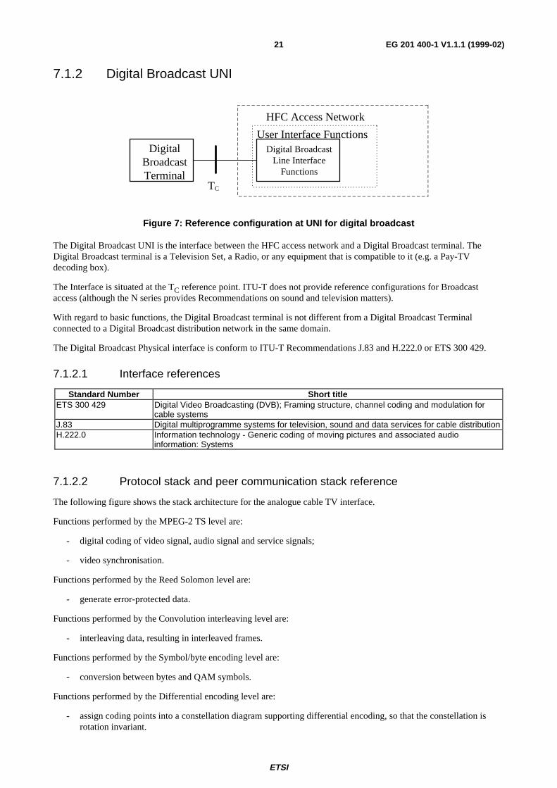
Figure 7: Reference configuration at UNI for digital broadcast
The Digital Broadcast UNI is the interface between the HFC access network and a Digital Broadcast terminal. TheDigital Broadcast terminal is a Television Set, a Radio, or any equipment that is compatible to it (e.g. a Pay-TVdecoding box).
The Interface is situated at the TC reference point. ITU-T does not provide reference configurations for Broadcastaccess (although the N series provides Recommendations on sound and television matters).
With regard to basic functions, the Digital Broadcast terminal is not different from a Digital Broadcast Terminalconnected to a Digital Broadcast distribution network in the same domain.
The Digital Broadcast Physical interface is conform to ITU-T Recommendations J.83 and H.222.0 or ETS 300 429.
7.1.2.1 Interface references
Standard Number Short titleETS 300 429 Digital Video Broadcasting (DVB); Framing structure, channel coding and modulation for
cable systemsJ.83 Digital multiprogramme systems for television, sound and data services for cable distributionH.222.0 Information technology - Generic coding of moving pictures and associated audio
information: Systems
7.1.2.2 Protocol stack and peer communication stack reference
The following figure shows the stack architecture for the analogue cable TV interface.
Functions performed by the MPEG-2 TS level are:
- digital coding of video signal, audio signal and service signals;
- video synchronisation.
Functions performed by the Reed Solomon level are:
- generate error-protected data.
Functions performed by the Convolution interleaving level are:
- interleaving data, resulting in interleaved frames.
Functions performed by the Symbol/byte encoding level are:
- conversion between bytes and QAM symbols.
Functions performed by the Differential encoding level are:
- assign coding points into a constellation diagram supporting differential encoding, so that the constellation isrotation invariant.

ETSI
EG 201 400-1 V1.1.1 (1999-02)22
Functions performed by the QAM level are:
- square \root raised cosine filtering;
- QAM modulation/demodulation.
MPEG-2 TS level
Reed Solomon level
Convolutional interleaving level
Symbol/byte encoding level
Differential encoding level
QAM level
Cable PMD level
Figure 8: Digital TV stack
The digital broadcast data is sent unidirectional from head end to the user. At the UNI the Digital TV stack levelfunctions are performed from bottom to top of the stack. The digital TV data signal under QAM format is embedded inthe HFC transport signal.
7.2 PSTN UNI
HFC Access Network
User Interface Functions
POTS Cable Network Termination
POTSTerminal
Z, TT
POTS LineInterfaceFunctions
Figure 9: Reference configuration at UNI for POTS
The PSTN UNI is the interface between the HFC access network and the POTS (Plain Old Telephone Service) terminal.The POTS terminal is a POTS Telephone or any equipment that is compatible to it (fax, data modem, ...).
The Interface is situated at the Z (TT) reference point.
With regard to the basic telephony functions, the PSTN Terminal is not different from a PSTN Terminal connected to aPSTN in the same domain.
The POTS interface is historically a country specific interface.
ETSI
EG 201 400-1 V1.1.1 (1999-02)23
7.2.1 Interface references
Standard Number Short titleEN 300 001 Attachments to the Public Switched Telephone Network (PSTN); General technical
requirements for equipment connected to an analogue subscriber interface in the PSTN
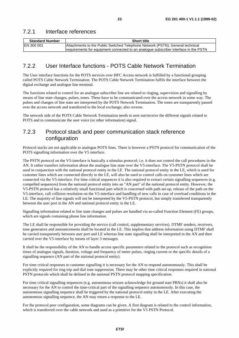
7.2.2 User Interface functions - POTS Cable Network Termination
The User interface functions for the POTS services over HFC Access network is fulfilled by a functional groupingcalled POTS Cable Network Termination. The POTS Cable Network Termination fulfils the interface between thedigital exchange and analogue line terminal.
The functions related to control for an analogue subscriber line are related to ringing, supervision and signalling bymeans of line state changes, pulses, tones. These have to be communicated over the access network in some way. Thepulses and changes of line state are interpreted by the POTS Network Termination. The tones are transparently passedover the access network and transferred to the local exchange; also reverse.
The network side of the POTS Cable Network Termination needs to sent out/receive the different signals related toPOTS and to communicate the user voice (or other information) signal.
7.2.3 Protocol stack and peer communication stack referenceconfiguration
Protocol stacks are not applicable to analogue POTS lines. There is however a PSTN protocol for communication of thePOTS signalling information over the V5 interface.
The PSTN protocol on the V5-interface is basically a stimulus protocol; i.e. it does not control the call procedures in theAN. It rather transfers information about the analogue line state over the V5-interface. The V5-PSTN protocol shall beused in conjunction with the national protocol entity in the LE. The national protocol entity in the LE, which is used forcustomer lines which are connected directly to the LE, will also be used to control calls on customer lines which areconnected via the V5-interface. For time critical sequences it is also required to extract certain signalling sequences (e.g.compelled sequences) from the national protocol entity into an "AN part" of the national protocol entity. However, theV5-PSTN protocol has a relatively small functional part which is concerned with path set-up, release of the path on theV5-interface, call collision resolution on the V5-interface and handling of new calls in case of overload conditions in theLE. The majority of line signals will not be interpreted by the V5-PSTN protocol, but simply transferred transparentlybetween the user port in the AN and national protocol entity in the LE.
Signalling information related to line state changes and pulses are handled via so-called Function Element (FE) groups,which are signals containing phone line information.
The LE shall be responsible for providing the service (call control, supplementary services). DTMF senders, receivers,tone generators and announcements shall be located in the LE. This implies that address information using DTMF shallbe carried transparently between user port and LE whereas line state signalling shall be interpreted in the AN and thencarried over the V5-interface by means of layer 3 messages.
It shall be the responsibility of the AN to handle access specific parameters related to the protocol such as recognitiontimes of analogue signals, duration, voltage and frequency of meter pulses, ringing current or the specific details of asignalling sequence (AN part of the national protocol entity).
For time critical responses to customer signalling it is necessary for the AN to respond autonomously. This shall beexplicitly required for ring trip and dial tone suppression. There may be other time critical responses required in nationalPSTN protocols which shall be defined in the national PSTN protocol mapping specification.
For time critical signalling sequences (e.g. autonomous seizure acknowledge for ground start PBXs) it shall also benecessary for the AN to control the time-critical part of the signalling sequence autonomously. In this case, theautonomous signalling sequence shall be triggered by the national protocol entity in the LE. After executing theautonomous signalling sequence, the AN may return a response to the LE.
For the protocol peer configuration, some diagrams can be given. A first diagram is related to the control information,which is transferred over the cable network and used as a primitive for the V5 PSTN Protocol.

ETSI
EG 201 400-1 V1.1.1 (1999-02)24
Access nodePOTS Phone PSTN Cable Network Termination
�
Z (TT)
Analog linesignal and info
controlfunctions
CablePMD
Cable MAC
CablePMD
FE ControlFE Control
Cable MAC
PSTN protocol
Figure 10: Protocol peer configuration for POTS signalling
A second diagram is related to the user analogue signal and tones.
Access nodePOTS Phone POTS Cable Network Termination
�Z (TT)
Analog lineinfo and tones
CablePMD
Cable MAC
CablePMD
Cable MAC
Modulation/demodulation
64kbit/s Channel
64kbit/s ChannelA/D and D/Aconversion
Modulation/demodulation
Figure 11: Protocol peer configuration for POTS user info and tones
7.3 N-ISDN UNI
N-ISDNTerminal
(N-TE), orNT2
N-ISDN LineInterfaceFunctions
T, TN
HFC Access Network
User Interface Functions
N-ISDN Cable Network Termination
Figure 12: Reference configuration at UNI for N-ISDN
The N-ISDN UNI is the interface between the HFC access network and the N-ISDN terminal or NT2. The N-ISDNterminal is an N-TE terminal or any equipment that is compatible to it (possibly with Terminal Adapter).

ETSI
EG 201 400-1 V1.1.1 (1999-02)25
The Interface is situated at the T (TN) reference point. The Reference configurations of ITU-T recommendation I.411apply.
With regard to basic functions, the N-ISDN terminal is not different from a N-ISDN Terminal connected to a N-ISDNlocal exchange in the same domain (see reference [3]).
The N-ISDN Physical interface is described in the ITU-T Recommendations I.430 for the Basic Access (BA) and ITU-TRecommendation I.431 for the Primary Rate Access (PRA).
7.3.1 Interface references
Standard Number Short titleI.411 ISDN user-network interfaces - Reference configurationsQ.921 ISDN user-network interface - Data link layer specificationQ.931 ISDN user-network interface layer 3specification for basic call control
7.3.1.1 Basic access
I.430 Basic user-network interface – Layer 1 specification
7.3.1.2 Primary access
I.431 Primary rate user-network interface – Layer 1 specification
7.3.2 User Interface functions - N-ISDN Cable Network Termination
The User interface functions for the N-ISDN services over HFC Access network is fulfilled by a functional groupingcalled N-ISDN Cable Network Termination. The N-ISDN Cable Network Termination fulfils the interface between thenetwork and the N-ISDN TE or NT2.
The type of accesses supported for a single customer are the following:
- multipoint layer 1 passive bus configuration at the coincident S and T reference point; any N-ISDN teleservice orbearer service to be supported;
- NT2 support.

ETSI
EG 201 400-1 V1.1.1 (1999-02)26
7.3.3 Protocol stack and peer communication stack reference
The protocol stacks for N-ISDN UNI, for basic and primary access are the following.
Q.931Network layer
OSI Layer stack N-ISDN UNI BA stack
BA: Basic AccessPRA: Primary Rate Access
Q.921
I.430Physical layer
Data link layer
Q.931
N-ISDN UNI PRA stack
Q.921
I.431
Figure 13: Protocol stack at N-ISDN UNI at T N reference point
The peer communication stack configuration for signalling, from NT1 view, is given in the following figure. Signallingat layer 2 and layer 3 is not interpreted in the HFC access network.
Q.931
Access nodeN-TE or NT2 N-ISDN Cable Network Termination
TN
I.430 or I.431D-channel
I.430 or I.431D-channel
Q.921
CablePMD
Modulation/demod
Cable MAC
CablePMD
Cable MAC
Modulation/demod
Figure 14: Protocol peer configuration for N-ISDN signalling
The peer communication stack configuration for B-channel info, from NT1 view, is given in the following figure. Theinformation is transported over the access network to the telecommunication network.

ETSI
EG 201 400-1 V1.1.1 (1999-02)27
Access nodeN-TE or NT2 N-ISDN Cable Network Termination
TN
I.430 or I.431B-channel
I.430 or I.431B-channel Cable
PMD
Modulation/demod
B-channel info
Cable MAC
CablePMD
Cable MAC
Modulation/demod
Figure 15: Protocol peer configuration for N-ISDN user information
7.4 Internet Terminal UNI
HFC Access Network
User Interface Functions
IP Cable Network Term. Functions
InternetTerminal
or IP LAN
Internet portFunctions
TI
Figure 16: Reference configuration at UNI for Internet
The Internet UNI at the TI reference point is the interface between the HFC access network and an Internet terminal. AInternet terminal is a PC or any other workstation or digital equipment that has external communication capability basedon a (the) standard IP protocol and underlying layers.
The User Interface functions are practically realised by a device called "IP Cable Network Termination".

ETSI
EG 201 400-1 V1.1.1 (1999-02)28
7.4.1 Interface references
Standard Number Short titleIETF RFC 894 IP Datagrams over Ethernet NetworksIETF RFC 1042 IP Datagrams over IEEE 802 NetworksIETF Internet-draft draft-ietf-ipcdn-ipcabledata-spec-00.txt
IP Over Cable Data Network service
ISO/IEC 10038 [7] (IEEE Std 802.1D) Information technology - Telecommunications and information exchangebetween systems - Local area networks - Media access control (MAC)bridges
ISO/IEC 8802-2 [8] Information technology - Telecommunications and information exchangebetween systems - Local and metropolitan area networks- Specificrequirements - Part 2: Logical link control
ISO/IEC 8802-3 [9] Information technology - Telecommunications and information exchangebetween systems - Local and metropolitan area networks - Part 3: Carriersense multiple access with collision detection (CSMA/CD) access methodand physical layer specifications
ETS 300 429 Digital Video Broadcasting (DVB); Framing structure, channel coding andmodulation for cable systems
ETS 300 800 Digital Video Broadcasting (DVB); Interaction channel for Cable TVdistribution systems (CATV)
7.4.2 User interface functions - IP Cable Network Termination
The User interface functions for the IP data over HFC Access network is fulfilled by a functional grouping called IPCable Network Termination. The IP Cable Network Termination used at the customer premises is called IP CableNetwork Termination.
7.4.2.1 Definition
IP Cable Network Termination
A IP Cable Network Termination is a device that allows high-speed access to the Internet via a HFC access network. AIP Cable Network Termination will typically have two connections, one to the cable wall outlet to the network and theother to the Internet CPE equipment.
7.4.2.2 Functions and Technology
The IP Cable Network Termination technology provides an "always on" feature for individuals to have a high-speedaccess to the Internet.
IP Cable Network Termination capabilities vary widely.
In the downstream direction (from the network to the CPE), data rates can be anywhere up to 38,1 Mbit/s per 8 MHzchannel. Few terminals will be capable of connecting at such high data rates, so a more realistic number is 6 Mbit/s -9 Mbit/s.
In the upstream direction (from computer to network), data rates can be 3,088 Mbit/s, 1,544 Mbit/s or 256 kbit/s.
In case of IP Cable Network Termination deployment, an asymmetric set-up will probably be more common than asymmetric set-up. In an asymmetric scheme, the downstream channel has a much higher bandwidth allocation (fasterdata rate) than the upstream. Current Internet applications tend to be asymmetric in nature. Activities such as WorldWide Web navigating and newsgroup reading send much more data down to the computer than to the network. Imagefiles and audio and video files are very bandwidth intensive in the downstream direction. Mouse clicks (URL requests)and e-mail messages are not bandwidth intensive in the upstream direction.
The fact that the word "modem" is used to describe this device can be a little misleading. Yes, it is a modem in the truesense of the word - it MOdulates and DEModulates signals. But the similarity ends there because IP Cable NetworkTerminations are more complicated than the traditional telephone modems. IP Cable Network Terminations can containmodem functions, but also tuner, encryption/decryption, medium access, and other functions.

ETSI
EG 201 400-1 V1.1.1 (1999-02)29
Typically, a IP Cable Network Termination sends and receives data in two slightly different fashions:
- In the downstream direction, the digital data is modulated and then placed on a typical (e.g. 6 MHz to 8 MHz)television carrier, somewhere between 47 MHz and 860 MHz. There are several modulation schemes, but the twomost popular are QPSK (up to ~10 Mbit/s) and QAM64 (up to ~36 Mbit/s). This signal can be placed in achannel adjacent to TV signals on either side without disturbing the cable television video signals.
- In a two-way activated cable network, the upstream (also known as the reverse path) is transmitted between5 MHz and 65 MHz. The lower part of this bandwidth tends to be a noisy environment, with lots of interferencefrom, e.g. CB radios and impulse noise from home appliances. Since cable networks are tree and branchnetworks, all this noise gets added together as the signals travel upstream, combining and increasing (noisefunnelling). Due to this problem, QPSK or a similar modulation scheme will be used in the upstream direction,because QPSK is more robust scheme than higher order modulation techniques in a noisy environment. QPSK ishowever "slower" than QAM.
7.4.3 Protocol stack and peer communication stack reference
The Internet IETF recommends multiple datalink/ physical link combinations on which the IP is able to run. A typicalprotocol stack is given in the following figure. Ethernet 10BaseT is a commonly used method.
RFC 1042/RFC 894Internet Protocol (IP)Network layer
OSI Layer stack Internet UNI at TI stack
LLC: Logical Link ControlMAC: Medium Access Control
ISO/IEC 8802.3 10BASE-T or 100BASE-T
MAC sublayer
ISO/IEC 8802-2 LLC sublayerLLC sublayer
ISO/IEC 8802-3 MAC sublayer
Physical layer
Data link layer
NOTE: Other options below the IP protocol are possible; when used, the underlying IP protocol stack needs to bereplaced in all appropriate figures.
Figure 17: Protocol stack at Internet UNI on T I reference point
ETSI
EG 201 400-1 V1.1.1 (1999-02)30
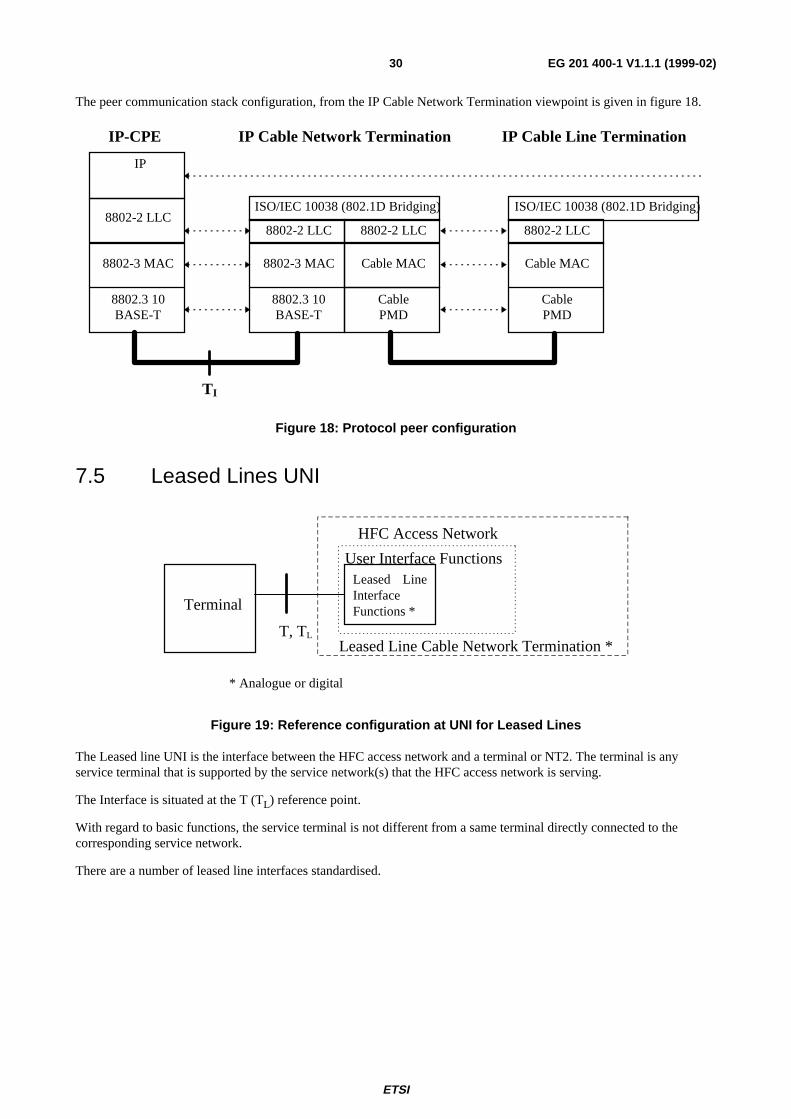
The peer communication stack configuration, from the IP Cable Network Termination viewpoint is given in figure 18.
IP
IP-CPE IP Cable Line TerminationIP Cable Network Termination
TI
8802.3 10BASE-T
8802-2 LLC
8802-3 MAC
8802.3 10BASE-T
8802-2 LLC
8802-3 MAC
CablePMD
ISO/IEC 10038 (802.1D Bridging)
8802-2 LLC
Cable MAC
CablePMD
Cable MAC
8802-2 LLC
ISO/IEC 10038 (802.1D Bridging)
Figure 18: Protocol peer configuration
7.5 Leased Lines UNI
Terminal
Leased LineInterfaceFunctions *
* Analogue or digital
T, TL
HFC Access Network
User Interface Functions
Leased Line Cable Network Termination *
Figure 19: Reference configuration at UNI for Leased Lines
The Leased line UNI is the interface between the HFC access network and a terminal or NT2. The terminal is anyservice terminal that is supported by the service network(s) that the HFC access network is serving.
The Interface is situated at the T (TL) reference point.
With regard to basic functions, the service terminal is not different from a same terminal directly connected to thecorresponding service network.
There are a number of leased line interfaces standardised.

ETSI
EG 201 400-1 V1.1.1 (1999-02)31
7.5.1 Interface references
Standard Number Short titleETS 300 288 Business TeleCommunications (BTC); 64 kbit/s digital unrestricted leased line with octet
integrity (D64U); Network interface presentationETS 300 418 Business TeleCommunications (BTC); 2 048 kbit/s digital unstructured and structured leased
lines (D2048U and D2048S); Network interface presentationETS 300 448 Business TeleCommunications (BTC); Ordinary quality voice bandwidth 2-wire analogue leased
line (A2O); Connection characteristics and network interface presentationETS 300 449 Business TeleCommunications (BTC); Special quality voice bandwidth 2-wire analogue leased
line (A2S); Connection characteristics and network interface presentationETS 300 451 Business Telecommunications (BTC); Ordinary quality voice bandwidth 4-wire analogue leased
line (A4O); Connection characteristics and network interface presentationETS 300 452 Business Telecommunications (BTC); Special quality voice bandwidth 4-wire analogue leased
line (A4S); Connection characteristics and network interface presentationETS 300 766 Business TeleCommunications (BTC); Multiple 64 kbit/s digital unrestricted leased lines with
octet integrity presented at a structured 2 048 kbit/s interface at either or both ends (D64M);Connection characteristics and network interface presentation
ETS 300 686 Business TeleCommunications (BTC); 34 Mbit/s and 140 Mbit/s digital leased lines (D34U,D34S, D140U and D140S); Network interface presentation
ETS 300 687 Business TeleCommunications (BTC); 34 Mbit/s digital leased lines (D34U and D34S);Connection characteristics
ETS 300 688 Business TeleCommunications (BTC); 140 Mbit/s digital leased lines (D140U and D140S);Connection characteristics
ETS 300 689 Business TeleCommunications (BTC); 34 Mbit/s digital leased lines (D34U and D34S); Terminalequipment interface
ETS 300 690 Business TeleCommunications (BTC); 140 Mbit/s digital leased lines (D140U and D140S);Terminal equipment interface
TBR 25 Business TeleCommunications (BTC); 140 Mbit/s digital unstructured and structured leasedlines (D140U and D140S); Attachment requirements for terminal equipment interface
7.5.2 User Interface functions - Leased Cable Network Termination
The User interface functions for the leased line services over HFC Access network is fulfilled by a functional groupcalled Leased line Cable Network Termination. The leased line Cable Network Termination fulfils the interface betweenthe network and the User plane functions of TE. Signalling is not an issue.
Leased line user interface functions are limited to core functions.
7.5.3 Protocol stack and peer communication stack reference
This is depending upon the service offered. User information is modulated/demodulated and handled via the CableMAC function and the cable PMD function transmitted over the HFC transport network, or reverse.

ETSI
EG 201 400-1 V1.1.1 (1999-02)32
8 Service Node Interfaces (SNI) (Access NodeInterface)
8.1 Broadcast Service
Head End
Broadcast ServiceBroadcast Ser-vice Interface
Functions
PC or MC
Figure 20: Reference configuration at SNI for Broadcast
This interface has no typical access network interfaces. The interface is identical to the interface on TC. The interfacecan be analogue, but may support digital coded information.
8.2 PSTN Service specific Service nodeA service specific service node is only dedicated to one single service (ITU-T Recommendation G.902). In this case theinterface is dedicated to PSTN.
POTS Cable Line Termination
HFC Access NetworkHead End
PSTNHFC Interface
FunctionsPSTN Network
InterfaceFunctions
V5-N
Figure 21: Reference configuration at SNI for PSTN
The V5.1-N interface consists of a 2 048 kbit/s interface as defined in ETS 300 166 and ETS 300 167.
The V5.2-N interface may have between 1 and 16 2048 kbit/s interface links.
Descriptions to be found in ETS 300 324 for V5.1-N and in ETS 300 347 for V5.2-N.
8.2.1 Interface references
Standard Number Short titleG.964 [5] / ETS 300 324 V5.1 InterfaceG.965 [6] / ETS 300 347 V5.2 Interface
8.2.2 Network interface functions - PSTN Cable Line Termination
The Network interface functions for the PSTN information over HFC Access network is fulfilled by a functionalgrouping called PSTN Cable Line Termination. The PSTN Cable Line Termination is located at the Head End.

ETSI
EG 201 400-1 V1.1.1 (1999-02)33
8.2.3 Protocol stack and peer communication stack referenceconfigurations
8.2.3.1 Protocol stacks
8.2.3.1.1 V5.1N interface
The following figure shows the protocol architecture for the V5.1 interface. The functions performed are defined asfollows (more information can be obtained in the V5.1 recommendation).
- Envelope function sublayer of LAPV5 (LAPV5-EF).
- Data link sublayer of LAPV5 (LAPV5-DL).
- Sublayer-to-sublayer communication and mapping function.
- PSTN signalling protocol specification and layer 3 multiplexing.
- Control protocol.
Stack at Local ExchangeOSI Stack at AN side
Mapping
LAPV5-EF
C64
LAPV5-DL
Mapping
LAPV5-EF
C64
PSTN
LAPV5-DL
Networklayer
Physicallayer
Data linklayer
ControlPSTN Control
Figure 22: Protocol stacks for V5.1 N for PSTN
8.2.3.1.2 V5.2N interface
The following figure shows the protocol architecture for the V5.2 interface. The functions performed are defined asfollows (more information can be obtained in the V5.2 recommendation):
- envelope function sublayer of LAPV5 (LAPV5-EF);
- data link sublayer of LAPV5 (LAPV5-DL);
- sublayer-to-sublayer communication and mapping function;
- general layer 3 protocol structures;
- PSTN signalling protocol specification;
- control protocol;
- link control protocol;
- BCC protocol;
- protection protocol.

ETSI
EG 201 400-1 V1.1.1 (1999-02)34
Stack at Local ExchangeOSI Stack at AN side
Mapping
LAPV5-EF
C64
PSTN
LAPV5-DL
Networklayer
Physicallayer
Data linklayer
Prot. Port/link
Contr. BCC
Mapping
LAPV5-EF
C64
PSTN
LAPV5-DL
Prot. Port/link
Contr. BCC
Figure 23: Protocol stacks for V5.2 N
8.2.3.2 Protocol peer configurations
The following figure shows the Protocol peer configuration for the User information for POTS.
Local ExchangPSTNCable Line Termination
PSTN CableNetwork Termination
V5N
CablePMD
Cable MAC64kbit/s Channel
CablePMD
Cable MAC
C64 C64
Modulation/demod. Modulation/demod.
Figure 24: Protocol peer configuration for POTS User information

ETSI
EG 201 400-1 V1.1.1 (1999-02)35
8.2.3.2.1 V5.1 interface
The following figures show different Protocol peer stack configurations for different contexts.
Local Exchange
V5.1N
CablePMD
Cable MAC
CablePMD
Cable MAC
Mapping
LAPV5-EF
C64
PSTN or Control PSTN or Control
LAPV5-DL
FEControl
Mapping
LAPV5-EF
C64
LAPV5-DL
PSTN CableNetwork Termination
PSTNCable Line Termination
Figure 25: Protocol peer configuration for V5.1 N signalling functions for PSTN signalling
8.2.3.2.2 V5.2 interface
The following figures show different Protocol peer stack configurations for different contexts.
PSTN CableNetwork
TerminationLocal Exchange
PSTN CableLine Termination
V5.2N
CablePMD
Cable MAC
CablePMD
Cable MAC
Mapping
LAPV5-EF
C64
PSTN or Prot. or Port/linkor Control or BCC
LAPV5-DL
FEControl
Mapping
LAPV5-EF
C64
LAPV5-DL
PSTN or Prot. or Port/linkor Control or BCC
Figure 26: Protocol peer configuration for V5.2 N signalling functions for PSTN signalling

ETSI
EG 201 400-1 V1.1.1 (1999-02)36
8.3 N-ISDN Service specific Service nodeA service specific service node is dedicated to only one service (ITU-T Recommendation G.902). In this case theinterface is dedicated N-ISDN services only.
N-ISDN Cable LineTermination
HFC Access NetworkHead End
N-ISDNHFC Interface
FunctionsN-ISDNNetworkInterfaceFunctions V5-N
Figure 27: Reference configuration at SNI for N-ISDN
The V5.1-N interface consists of a 2 048 kbit/s interface as defined in ETS 300 166 and ETS 300 167.
The V5.2-N interface may have between 2 048 kbit/s and 16 x 2 048 kbit/s interface links.
Descriptions to be found in ETS 300 324 for V5.1-N and in ETS 300 347 for V5.2-N.
8.3.1 Interface references
Standard Number Short titleG.964 [5] / ETS 300 324 V5.1 InterfaceG.965 [6] / ETS 300 347 V5.2 Interface
8.3.2 Network interface functions - N-ISDN Cable Line Termination
The Network interface functions for the N-ISDN information over HFC Access network is fulfilled by a functionalgrouping called N-ISDN Cable Line Termination. The N-ISDN Cable Line Termination is located at the Head End.
8.3.3 Protocol stack and peer communication stack referenceconfigurations
8.3.3.1 Protocol stacks
8.3.3.1.1 V5.1N interface
The following figure shows the protocol architecture for the V5.1 interface. The functions performed are defined asfollows (more information can be obtained in the V5.1 recommendation):
- envelope function sublayer of LAPV5 (LAPV5-EF);
- data link sublayer of LAPV5 (LAPV5-DL);
- frame relaying sublayer of the AN (AN-FR);
- sublayer-to-sublayer communication and mapping function;
- layer 3 multiplexing;
- control protocol.

ETSI
EG 201 400-1 V1.1.1 (1999-02)37
Stack at Local ExchangeOSI Stack at AN side
Mapping
LAPV5-EF
C64D16
LAPV5-DL
AN framerelay
Mapping
LAPV5-EF
C64
LAPV5-DL
Networklayer
Physicallayer
Data linklayer
Control Control Q.931
Q.921
Figure 28: Protocol stacks for V5.1 N
8.3.3.1.2 V5.2N interface
The following figure shows the protocol architecture for the V5.2 interface. The functions performed are defined asfollows (more information can be obtained in the V5.2 recommendation):
- envelope function sublayer of LAPV5 (LAPV5-EF);
- data link sublayer of LAPV5 (LAPV5-DL);
- frame relaying sublayer of the AN (AN-FR);
- sublayer-to-sublayer communication and mapping function;
- general layer 3 protocol structures;
- control protocol;
- link control protocol;
- BCC protocol;
- protection protocol.
Stack at Local ExchangeOSI Stack at AN side
Mapping
LAPV5-EF
C64D16
LAPV5-DL
AN framerelay
Networklayer
Physicallayer
Data linklayer
Prot. Port/link
Contr. BCC
Mapping
LAPV5-EF
C64
LAPV5-DL
Prot. Port/link
Contr. BCC Q.931
Q.921
Figure 29: Protocol stacks for V5.2 N

ETSI
EG 201 400-1 V1.1.1 (1999-02)38
8.3.3.2 Protocol peer configurations
The following figure shows the Protocol peer configuration for the User information for N-ISDN.
Local ExchangeN-ISDN CableNetwork Termination
N-ISDNCable Line Termination
V5N
CablePMD
Cable MAC
CablePMD
Cable MACC64 C64
Modulation/demod.
Figure 30: Protocol peer configuration for N-ISDN User information
8.3.3.2.1 V5.1 interface
The following figures show different Protocol peer stack configurations for different contexts.
Local Exchange
V5.1N
CablePMD
Cable MAC
CablePMD
Cable MAC
Mapping
LAPV5-EF
C64
D16
Control Control
LAPV5-DL
AN framerelay
Mapping
LAPV5-EF
C64
LAPV5-DL
N-ISDN CableNetwork Termination
N-ISDNCable Line Termination
Figure 31: Protocol peer configuration for V5.1 N signalling functions except N-ISDN signalling

ETSI
EG 201 400-1 V1.1.1 (1999-02)39
Local Exchange
V5.1N
CablePMD
Cable MAC
D16
CablePMD
Cable MAC
Mapping
LAPV5-EF
Bridging
C64
D16
AN framerelay
Mapping
LAPV5-EF
C64
Q.931
Q.921
N-ISDN CableNetwork Termination
N-ISDNCable Line Termination
Figure 32: Protocol peer configuration for V5.1 N for N-ISDN signalling
8.3.3.2.2 V5.2 interface
The following figures show different Protocol peer stack configurations for different contexts.
N-ISDN CableNetwork
TerminationLocal Exchange
N-ISDN CableLine Termination
V5.2N
CablePMD
Cable MAC
CablePMD
Cable MAC
Mapping
LAPV5-EF
C64
D16
Prot. or Port/link orControl or BCC
LAPV5-DL
AN framerelay
Mapping
LAPV5-EF
C64
LAPV5-DL
Prot. or Port/link orControl or BCC
Figure 33: Protocol peer configuration for V5.2 N signalling functions except N-ISDN signalling
N-ISDN CableNetwork
TerminationLocal Exchange
N-ISDN CableLine Termination
V5.2N
CablePMD
Cable MAC
CablePMD
Cable MAC
Mapping
LAPV5-EF
C64
D16/64
AN framerelay
Mapping
LAPV5-EF
C64
Q.931
Q.921
Figure 34: Protocol peer configuration for V5.2 N, for ISDN signalling

ETSI
EG 201 400-1 V1.1.1 (1999-02)40
8.4 PSTN/N-ISDN Modular Service nodeA modular service node may be dedicated to more than one service (ITU-T Recommendation G.902). In this case theinterface is dedicated to both PSTN and N-ISDN services.
POTS Cable LineTermination
HFC Access NetworkHead End
PSTN/N-ISDNHFC Interface
FunctionsN-ISDNNetworkInterfaceFunctions V5-N
Figure 35: Reference configuration at SNI for PSTN/N-ISDN
The V5.1-N interface consists of a 2 048 kbit/s interface as defined in ETS 300 166 and ETS 300 167.
The V5.2-N interface may have between 1 and 16 2 048 kbit/s interface links.
Descriptions to be found in ETS 300 324 for V5.1-N and in ETS 300 347 for V5.2-N.
8.4.1 Interface references
Standard Number Short titleG.964 [5] / ETS 300 324 N-ISDN V5.1 InterfaceG.965 [6] / ETS 300 347 N-ISDN V5.2 Interface
8.4.2 Network interface functions - PSTN/N-ISDN Cable Line Termination
The Network interface functions for the PSTN or N-ISDN information over HFC Access network is fulfilled by afunctional grouping called PSTN/N-ISDN Cable Line Termination. The PSTN/N-ISDN Cable Line Termination islocated at the Head End.
8.4.3 Protocol stack and peer communication stack referenceconfigurations
8.4.3.1 Protocol stacks
8.4.3.1.1 V5.1N interface
The following figure shows the protocol architecture for the V5.1 interface. The functions performed are defined asfollows (more information can be obtained in the V5.1 recommendation):
- envelope function sublayer of LAPV5 (LAPV5-EF);
- data link sublayer of LAPV5 (LAPV5-DL);
- frame relaying sublayer of the AN (AN-FR);
- sublayer-to-sublayer communication and mapping function;
- PSTN signalling protocol specification and layer 3 multiplexing;
- control protocol.

ETSI
EG 201 400-1 V1.1.1 (1999-02)41
Stack at Local ExchangeOSI Stack at AN side
Mapping
LAPV5-EF
C64D16
LAPV5-DL
AN framerelay
Mapping
LAPV5-EF
C64
PSTN
LAPV5-DL
Networklayer
Physicallayer
Data linklayer
ControlPSTN Control Q.931
Q.921
Figure 36: Protocol stacks for V5.1 N
8.4.3.1.2 V5.2N interface
The following figure shows the protocol architecture for the V5.2 interface. The functions performed are defined asfollows: (more information can be obtained in the V5.2 recommendation)
- envelope function sublayer of LAPV5 (LAPV5-EF);
- data link sublayer of LAPV5 (LAPV5-DL);
- frame relaying sublayer of the AN (AN-FR);
- sublayer-to-sublayer communication and mapping function;
- general layer 3 protocol structures;
- PSTN signalling protocol specification;
- control protocol;
- link control protocol;
- BCC protocol;
- protection protocol.
Stack at Local ExchangeOSI Stack at AN side
Mapping
LAPV5-EF
C64D16
PSTN
LAPV5-DL
AN framerelay
Networklayer
Physicallayer
Data linklayer
Prot. Port/link
Contr. BCC
Mapping
LAPV5-EF
C64
PSTN
LAPV5-DL
Prot. Port/link
Contr. BCC Q.931
Q.921
Figure 37: Protocol stacks for V5.2 N
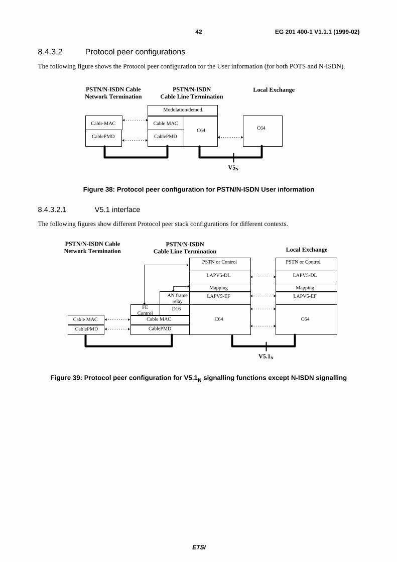
ETSI
EG 201 400-1 V1.1.1 (1999-02)42
8.4.3.2 Protocol peer configurations
The following figure shows the Protocol peer configuration for the User information (for both POTS and N-ISDN).
Local ExchangePSTN/N-ISDN CableNetwork Termination
PSTN/N-ISDNCable Line Termination
V5N
CablePMD
Cable MAC
CablePMD
Cable MACC64 C64
Modulation/demod.
Figure 38: Protocol peer configuration for PSTN/N-ISDN User information
8.4.3.2.1 V5.1 interface
The following figures show different Protocol peer stack configurations for different contexts.
Local Exchange
V5.1N
CablePMD
Cable MAC
CablePMD
Cable MAC
Mapping
LAPV5-EF
C64
D16
PSTN or Control PSTN or Control
LAPV5-DL
FEControl
AN framerelay
Mapping
LAPV5-EF
C64
LAPV5-DL
PSTN/N-ISDN CableNetwork Termination
PSTN/N-ISDNCable Line Termination
Figure 39: Protocol peer configuration for V5.1 N signalling functions except N-ISDN signalling

ETSI
EG 201 400-1 V1.1.1 (1999-02)43
Local Exchange
V5.1N
CablePMD
Cable MAC
D16
CablePMD
Cable MAC
Mapping
LAPV5-EF
Bridging
C64
D16
AN framerelay
Mapping
LAPV5-EF
C64
Q.931
Q.921
PSTN/N-ISDN CableNetwork Termination
PSTN/N-ISDNCable Line Termination
Figure 40: Protocol peer configuration for V5.1 N for N-ISDN signalling
8.4.3.2.2 V5.2 interface
The following figures show different Protocol peer stack configurations for different contexts.
PSTN/N-ISDNCable NetworkTermination
Local ExchangePSTN/N-ISDN Cable
Line Termination
V5.2N
CablePMD
Cable MAC
CablePMD
Cable MAC
Mapping
LAPV5-EF
C64
D16
PSTN or Prot. or Port/inkor Control or BCC
LAPV5-DL
FEControl
AN framerelay
Mapping
LAPV5-EF
C64
LAPV5-DL
PSTN or Prot. or Port/inkor Control or BCC
Figure 41: Protocol peer configuration for V5.2 N signalling functions except N-ISDN signalling

ETSI
EG 201 400-1 V1.1.1 (1999-02)44
PSTN/N-ISDNCable NetworkTermination
Local ExchangePSTN/N-ISDN Cable
Line Termination
V5.2N
CablePMD
Cable MAC
CablePMD
Cable MAC
Mapping
LAPV5-EF
C64
D16/64
AN framerelay
Mapping
LAPV5-EF
C64
Q.931
Q.921
Figure 42: Protocol peer configuration for V5.2 N, for ISDN signalling
8.5 Internet networkThe Internet network has the following interface from the access network.
HFC Access Network Head End
Head End IP Cable NetworkLine Termination functions
INTERNETHFC Interface
Functions
InternetNetworkInterfaceFunctions
V5-I
Figure 43: Reference configuration at SNI for Internet
This interface has no typical access network functions. The interface is identical to the interface on TI (UNI for Internet),but lower layers may differ.
8.5.1 Interface references
Standard Number Short titleIETF RFC 791 Internet ProtocolIETF RFC 894 IP Datagrams over Ethernet NetworksIETF RFC 1042 IP Datagrams over IEEE 802 NetworksIETF Internet-draft draft-ietf-ipcdn-ipcabledata-spec-00.txt
IP Over Cable Data Network service
ISO/IEC 10038 [7] (IEEE Std 802.1D) Media Access Control BridgesISO/IEC 8802-2 [8] Logical Link ControlISO/IEC 8802-3 [9] CSMA/CD)ITU-T Recommendation I.361 B-ISDN ATM layer specificationITU-T Recommendation I.363 AAL layerITU-T Recommendation I.432 ATM Physical interfaces

ETSI
EG 201 400-1 V1.1.1 (1999-02)45
8.5.2 Network interface functions - IP Cable Line Termination
The Network interface functions for the IP data over HFC Access network is fulfilled by a functional grouping called IPCable Line Termination. The IP Cable Line Termination used at the Head End is called IP Cable Line Termination.
8.5.3 Protocol stack and peer communication stack reference
8.5.3.1 Protocol stacks
There are several methods for computer connection. Some protocol stacks are shown in the following figures.
RFC 1042/RFC 894Internet Protocol (IP)Network layer
OSI Layer stack Internet UNI at V5I stack
ISO/IEC 8802.3 10BASE-T or100 BASE-TPh i l l
LLC: Logical Link ControlMAC: Medium Access Control
MAC sublayer
ISO/IEC 8802-2 LLCLLC sublayer
ISO/IEC 8802-3 MAC
Physical layer
Data link layer
Figure 44: Protocol stack at Internet SNI on V5 I reference point (1)
RFC 1042/RFC 894Internet Protocol (IP)Network layer
OSI Layer stack Internet UNI at V5I stack
Layer 1
PH layer
ATM layer
Data link layer
I.432.xseries of interfaces
AAL: ATM Adaption LayerATM: Asynchronous Transfer Mode
I.363.5 AAL5
I.361 ATM
Figure 45: Protocol stack at Internet SNI on V5 I reference point (2)

ETSI
EG 201 400-1 V1.1.1 (1999-02)46
8.5.3.2 Protocol peer communication
The peer communication stack configuration, from the IP Cable Line Termination viewpoint is given in figure 46.
IP
IP Cable Network Term. IP-RouterIP Cable Line Term.
V5I
Seeprotocolstacks
forInternet
SNI
Seeprotocolstacks
forInternet
SNICablePMD
Bridging
8802-2 LLC
Cable MAC
CablePMD
Cable MAC
8802-2 LLC
ISO IEC 10038 (802.1D Bridging )
Figure 46: Protocol peer configuration
8.6 Leased lines Specific Service networkAt the SNI the HFC Leased line may be connected to a specific service network, dedicated to the particular service, orto a leased line service network. The first case may be found in other subclauses dealing with the particular servicenetwork. The second case is handled in this subclause.
HFC Access Network
Leased Line Cable LineTermination
Head End
Leased LineService Network
Leased LineInterfaceFunctions
V5-L
Figure 47: Reference configuration at SNI for Leased line
The V5.1-L interface is not defined in any standard. It is identical to the appropriate TL.
8.6.1 Interface references
None
8.6.2 Network interface functions - Leased Line Cable Line Termination
The Leased Line Network interface functions for the leased line services over HFC Access network is fulfilled by afunctional group called Leased line Cable Line Termination. The Leased Line Cable Line Termination is located at theHead End.
Leased line network interface functions are limited to core functions.
8.6.3 Protocol stack and peer communication stack referenceconfigurations
This is depending upon the service offered. Service information is modulated/demodulated and handled via the CableMAC function and the cable PMD function transmitted over the HFC transport network, or reverse.

ETSI
EG 201 400-1 V1.1.1 (1999-02)47
9 Internal HFC Access Network Aspects
9.1 Interface referencesStandard Number Short title
ETS 300 429 DVB; Framing structure, channel coding and modulation for cable systemsETS 300 800 DVB; Interaction channel for cable TV distribution systems
9.2 Internal HFC Access Network Structure
CON: ConnectorONU: Optical Network UnitOLT: Optical Line Termination
HFC Access Network
OLT
ONU
FiberCoax
FiberNode
SpecificNetwork
Type
AccessNodeUser
TerminalType
SpecificInterface
CON.TAP
UserTerminal RF
InterfaceUnit
HeadendUser Interfacefunctions(UIF)
Figure 48: Internal HFC Access Network Structure
The User Interface Functions entity is located at the user side in the HFC Access Network and contains the interface tothe User terminal equipment(s).
The Head End entity is located at the network side of the HFC access network, and contains interfaces to the specifictelecommunication networks.
The internal HFC access network control communication between User Interface Functions and the Head End is bydigital information which is packaged in RF frequencies. The HFC access network (transparent) informationcommunication is also by RF frequencies.
The transmission of RF signals between Head End and User Interface Functions is over an HFC transmission network,partly consisting of fiber and partly consisting of coax. The fibre can go the Cabinet (FTTCab), to the Building (FTTB),to the Curb (FTTC), or to the Home (FTTH). The given optical access networks are described in ITU-TRecommendation G.983.
The Head End contains a combiner/splitter for combination/splitting of the RF frequency bands.
Access
Node
Access
Node

ETSI
EG 201 400-1 V1.1.1 (1999-02)48
9.3 HFC Access network channel structure and protocolsThe channel structure is not standardised all over Europe. There are a number of national specifications describing thechannel structure for analogue TV. The channel structure on the fibre/cable for digital TV and the other services is notdefined yet in Europe nor international.
The Cable PMD encoding schemes for the different services (except broadcast service) are also open.
The protocols used in the Cable MAC layer are described by the ITU-T Recommendation J.112. In this recommendation3 standards are described. The 3 standards (Annex A-C) are intended for different regions of the world:
- A: Europe;
- B: North America;
- C: Japan.
The European version (annex A is identical with ETS 300 429 and ETS 300 800).

ETSI
EG 201 400-1 V1.1.1 (1999-02)49
BibliographyThe following material, though not specifically referenced in the body of the present document (or not publiclyavailable), gives supporting information.
IETF Internet-draft draft-ietf-ipcdn-ipcabledata-spec-00.txt (1996): "IP Over Cable Data Network service".
TR 101 615: "Network Aspects: Telecommunication Services and Networks Architecture".
ITU-T Recommendation G.983: "High speed optical access systems based on Passive Optical Network".

ETSI
EG 201 400-1 V1.1.1 (1999-02)50
History
Document history
V1.1.1 November 1998 Membership Approval Procedure MV 9901: 1998-11-03 to 1999-01-01
V1.1.1 February 1999 Publication
ISBN 2-7437-2838-8Dépôt légal : Février 1999