eh65v us eu7285 - subarupower.com
TRANSCRIPT

2ZZ9020155
ISSUE EMD-EU7285
OHV Gasoline Engines
EH63V/65V
PRINTED IN JAPANDecember 2011

AIR INDEX
Descriptive Term Applicable to Emissions Durability Period
Moderate - 50 hours (engine from 0 to 80 cc)125 hours (engine greater than 80 cc)
Intermediate - 125 hours (engine from 0 to 80 cc)250 hours (engine greater than 80 cc)
Extended - 300 hours (engine from 0 to 80 cc)500 hours (engine greater than 80 cc)
1000 hours (225 cc and greater)
WARNING:The engine exhaust from this product contains chemicals known to the State of California to cause cancer, birth defects or other reproductive harm.
To show compliance with California emission regulations, a hangtag has been provided displaying the Air Index level and durability period of this engine.
The Air Index level defines how clean an engine’s exhaust is over a period of time. A bar graph scaled from “0” (most clean) to “10” (least clean) is used to show an engine’s Air Index level. A lower Air Index level represents cleaner exhaust from an engine.
The period of time (in hours) that the Air Index level is measured is known as the durability period. Depending on the size of the engine, a selection of time periods can be used to measure the Air Index level (see below).
Notice : This hangtag must remain on this engine or piece of equipment, and only be removed by the ultimate purchaser before operation.
Notice : FEDERAL EMISSION COMPONENT DEFECT WARRANTY and CALIFORNIA EMISSION CONTROL WARRANTY are applicable to only those engines/ generators complied with EPA (Environmental Protection Agency) and CARB (California Air Resources Board) emission regulations in the U.S.A.
Notice : To the engines/generators exported to and used in the countries other than the U.S.A., warranty service shall be performed by the distributor in each country in accordance with the standard SUBARU engine/generator warranty policy as applicable.
(California Proposition 65)
(California only)
EH65V_us_EU7285 11.12.19 2:07 PM ページ01

FOREWORD
Thank you very much for purchasing a SUBARU ENGINE.
Your SUBARU ENGINE can supply the power to operate vari-ous sorts of machines and equipment.Please take a moment to familiarize yourself with the properoperation and maintenance procedures in order to maximizethe safe and efficient use of this product.Due to constant efforts to improve our products, certain proce-dures and specifications are subjected to change withoutnotice.When ordering spare parts, always give us the MODEL,SPECIFICATION and SERIAL NUMBER of your engine.Please fill in the following blanks after checking the specifica-tion number on your engine.
SPEC NO.
SERIAL NO.
E H
For your nearest distributor (and/or dealer), you are able to check at
our website of the following URL;
http://www.subaru-robin.jp
EH65V_us_EU7285 11.12.19 2:07 PM ページ0-1

CONTENTS
1.SAFETY PRECAUTIONS ・・・・・・・・・・・・・・・・・・・・・・・・・・・・12. COMPONENTS ・・・・・・・・・・・・・・・・・・・・・・・・・・・・・・・・・・・・・43. PRE-OPERATION CHECKS・・・・・・・・・・・・・・・・・・・・・・・・・・54. BATTERY INSTALLATION ・・・・・・・・・・・・・・・・・・・・・・・・・・・75. OPERATING YOUR ENGINE ・・・・・・・・・・・・・・・・・・・・・・・・・96. EASY TROUBLESHOOTING・・・・・・・・・・・・・・・・・・・・・・・・・127. SPARK ARRESTER (OPTIONAL)・・・・・・・・・・・・・・・・・・・・・148. MAINTENANCE SCHEDULE・・・・・・・・・・・・・・・・・・・・・・・・・159. "HOW-TO" MAINTENANCE・・・・・・・・・・・・・・・・・・・・・・・・・・1710. PREPARATIONS FOR STORAGE・・・・・・・・・・・・・・・・・・・・2111. SPECIFICATIONS ・・・・・・・・・・・・・・・・・・・・・・・・・・・・・・・・・・22
EH65V_us_EU7285 11.12.19 2:07 PM ページ0-2

SYMBOLS
USA and CANADA only
Read INSTRUCTIONSFOR USE before use.
The engine emits toxic gas can kill you in minutes.Do not run in an enclosed area.
Hot surface can burn you. Stay away if engine has been running.
Gasoline is extremely flammable and its vapors can explode.• Stop the engine before refueling.• Check for leakage from hoses and fittings.• Shut off fuel valve when the engine is not in use.
EH65V_us_EU7285 11.12.19 2:07 PM ページ0-3

EXHAUST PRECAUTIONS■ Never inhale exhaust gasses.
They contain carbon monoxide, acolorless, odorless and extremelydangerous gas which can causeunconsciousness or death.
■ Never operate the engine indoors orin a poorly ventilated area, such astunnel, cave, etc.
■ Exercise extreme care when operat-ing the engine near people oranimals.
■ Keep the exhaust pipe free of foreignobjects.
1. SAFETY PRECAUTIONS
FIRE PREVENTION■ Do not operate while smoking or near
an open flame.
■ Do not use around dry brush, twigs,cloth rags, or other flammable materi-als.
■ Keep the engine at least 3 feet (1 meter) away from buildings orother structures.
■ Keep the engine away from flamma-bles and other hazardous materials(trash, rags, lubricants, explosives).
REFUELING PRECAUTIONS■ Be sure to stop the engine prior to
refueling.
■ Do not overfill the fuel tank.
■ If fuel is spilt, wipe it away carefullyand wait until the fuel has driedbefore starting the engine.
■ After refueling, make sure that thefuel cap is secured to preventspillage.
Please make sure you review each precaution carefully.
-1-
EH65V_us_EU7285 11.12.19 2:07 PM ページ1

SURROUNDINGS■Operate the engine on a stable, level
surface free of small rocks, loosegravel, etc.
-2-
PROTECTIVE COVER■ Place the protective covers over
the rotating parts.If rotating parts such as the driveshaft, pulley, belt, etc. are leftexposed, they are potentiallyhazardous.To prevent injury, equip them withprotective covers or shrouds.
■ Be careful of hot parts.The muffler and other engine partsbecome very hot while the engine isrunning or just after it has stopped.Operate the engine in a safe areaand keep children away from therunning engine.
■ Never make adjustments on themachinery while it is connected to theengine, without first removing theignition cable from the spark plug.Turning the crankshaft by handduring adjusting or cleaning mightstart the engine, and machinery withit, causing serious injury to the opera-tor.
■ Never run the engine with governordisconnected, or operate at speedsin excess of 3600 rpm load.
NOTEOperating the engine at a steepincline may cause seizure due toimproper lubrication even with amaximum oil level.
EH65V_us_EU7285 11.12.19 2:07 PM ページ2

-3-
■ Drain the fuel when transporting theengine.
■ Do not move the engine while inoperation when it has been removedfrom the equipment.
■ Keep the unit dry (do not operate it inrainy conditions).
PRE-OPERATION CHECKS.■ Carefully check fuel hoses and joints
for looseness and fuel leakage.Leaked fuel creates a potentiallydangerous situation.
■ Check bolts and nuts for looseness.A loose bolt or nut may cause seriousengine trouble.
■ Check the engine oil and refill if neces-sary.
■ Check the fuel level and refill if neces-sary.Take care not to overfill the tank.
■Wear snug fitting working clothes whenoperating the engine.Loose aprons, towels, belt, etc., maybe caught in the engine or drive train,causing a dangerous situation.
PRECAUTIONS ON THE HANDLING OF THE WARNING LABEL■Warning labels are affixed to our engines with regard to particularly serious dangers.
When using the engines, please use them safely after carefully reading theinstruction manual and understanding the dangers.
Warning Label Exclusively for the United States and Canada
For use in the United States or Canada, please affix the label suited to the region from among the enclosed warning labels.
AVERTISSEMENTLire les INSTRUCTIONS POUR L'USAGE avant d’utiliser le moteur.
L'essence est extrêmement inflammable et ses vapeurs peuvent exploser.• Arrêter le moteur avant de faire le plein en combustible.• Vérifier toute présence de fuite à partir des tuyaux et garnitures.• Bloquer la soupape de carburant quand le moteur n’est pas utilisé.
Le moteur émet un gaz toxique qui peut tuer l’opérateur en quelques minutes. Ne pas utiliser le moteur dans un emplacement fermé.La surface chaude peut vous brûler.S’éloigner du moteur s’il est en marche.
ADVERTENCIALeer las INSTRUCCIONES PARA EL USO antes de utilizar el motor.
La gasolina es extremadamente inflamable y sus vapores pueden estallar.• Detener el motor antes de hacer el lleno en combustible • Comprobar si hay presencia de fuga a partir los tubos y guarniciones • Bloquear la válvula de combustible cuando no se utiliza el motor.
El motor emite un gas tóxico que puede matar el operador en algunos minutos. No utilizar el motor en un sitio cerrado.La superficie caliente puede quemarles.Alejarse del motor si es en marcha.
STOP
STOP
EH65V_us_EU7285 11.12.19 2:07 PM ページ3

-4-
2. COMPONENTS
REMARKS :
■ Fuel tank (filter incorporated type is recommended), valve and hoses arerequested to prepare and make arrangements for connecting properly to carbu-retor.
■ For starter motor operation, key switch (*) is recommended to be adopted ontothis engine. In combination with battery and cable to be prepared, proper electric wiringarrangements are needed before normal engine operation.
* : Control box with key switch incorporated is available as optional part.
Speed control lever
Oil filter
Oil drain plug(On both side)
Electric starterSpark plug cap
Choke lever
Air cleaner cover
Oil gauge(Oil filler cap)
Fuel pump
Blower housing
Governor lever
Voltageregulator
Spark plug cap
Engine emission label
Engine identificationlabel
Lifting eye
Oil drain plug
EH65V_us_EU7285 11.12.19 2:07 PM ページ4

3. PRE-OPERATION CHECKS
-5-
CHECK ENGINE OILBefore checking or refilling engine oil, be
sure the engine is located on a stable, level
surface and stopped.
■ If the oil level is below the lower levelline on the oil gauge, refill with theproper oil (see table) to the upperlevel.OIL CAPACITY : 2.0 L
■When filling oil in the engine, keep theengine at the horizontal position, andthen fill oil up to the upper mark of theoil gauge.
■When checking the oil level, do notscrew the oil level gauge into the fillerneck.
■When the engine is operated once, theoil level lowers a little. Make sure of filling oil once again, up to the uppermark of the oil gauge.
■ Change oil if it is contaminated.(See page 15 Maintenance Schedule.)
■ Use 4-stroke automotive detergent oilof API service class SE or higher grade(SG, SH or SJ is recommended).
■ If multi-grade oil is employed, oilconsumption tends to increase whenthe ambient temperature is high.
Oil level gauge
Oil filler
Upper level
Lower level
Oil drain plug
5W
10W
20W
#20
#30
#40
10W-30
10W-40
Singlegrade
Multigrade
Ambienttemperature
-20 -10 0 10 20 30 40
-4 14 32 50 68 86 104
EH65V_us_EU7285 11.12.19 2:07 PM ページ5

-6-
CHECK FUEL
■ The fuel tank shall be provided sepa-rately, because the engine is notequipped with fuel tank.Also fuel valve and strainer should beprepared.Make proper connection with fuelhoses to the fuel pump.
■Make sure of setting the fuel tank at a position lower than the carburetor level. If itis unavoidable to install the fuel tank at a high place, make sure of providing a fuelvalve at the outlet of the fuel tank.If the fuel tank is installed at a high place, make sure to close the fuel valve whenthe engine is not being operated.
■ A serious accident may occur when the fuel hose comes off. Make sure of insert-ing it firmly in the joint and fixing it securely with a hose clamp.
■ Use unleaded automotive gasoline only.● Unleaded regular/premium or reformulated gasoline containing no more than
10% Ethanol (E10), or 15% MTBE may also be used.
● Never use gasoline containing ethanol exceeding 10%, or MTBE exceeding15% because engine or fuel system damage could result.
● Never use stale or contaminated gasoline.
● Use of these non-recommended fuels may result in reduced performance and/ordenial of warranty.
■ Stop the engine and close the fuel valve before filling the fuel tank.
■Wipe off any spilled fuel before starting the engine.
WARNINGDo not refuel while smoking, nearan open flame or other potentialhazards.
Fuel filter
Fuel pump
Fuel inlet
EH65V_us_EU7285 11.12.19 2:07 PM ページ6

4. BATTERY INSTALLATION
-7-
CABLELENGTH
CABLEDIA.
WIRE GAUGE
AWG (BS)BWG SAE JIS
Less than1.5 m
7.3 mm 1 6 AV15
1.5 mto 2.5 m
8.5 mm 0 4 AV20
2.5 mto 4.0 m
10.8 mm 3/0 2 AV30
PARTS TO BE PREPARED■ Use a battery rated 12V-30AH or
larger.
■ Use key switch for starter motoroperation.
■ Use a proper cable and ground wireto connect battery and key switch.
BATTERY CABLE
For GROUND WIRE, use a flat braidedwire of 0.03 sq. in. or larger sectionalarea. (SAE GAUGE 4)
LA406 LA408
Cable
Earth (Ground) wire
25mm
6.5φ
7φ
8.5φ
KEY SWITCH CABLE
CABLELENGTH
CABLEDIA.
WIRE GAUGE
AWG (BS) BWG JIS
Less than1.5 m
1.5 mm 14 16 AV1.25
1.5 mto 3.0 m
1.9 mm 12 14 AV2
3.0 mto 5.0 m
2.4 mm 10 13 AV3
For starter motor operation, proper electric wiring arrangements are needed beforenormal engine operation.
EH65V_us_EU7285 11.12.19 2:07 PM ページ7

-8-
Battery12V-30AH
+ -Electric starter
terminal
Earth wire
Cable
Carburetor
IgnitionCoil
Key Switch (Option Parts)
GreenChargeCoil
RedRedYellowGrey
Black / WhiteBlack
Red
YellowBlack
White
Black
Black
Regulator
Oil Warning Lamp(Option Parts)
StopDiode
Electricstarter
OilPressureSwitch
GTerminalKey
PositionOFF
RUN
START
M B L S
Battery12V-30AH
+ -
(WIRING DIAGRAM)
Select wires of proper gauge and connect battery and key switch as shown by thedotted line in the wiring diagram.
WIRING■ Connect positive terminal of the
electric starter and positive termi-nal of the battery with batterycable.
■Ground negative terminal of thebattery to the body of engine ormachine with ground wire.
NOTETighten bolts and nuts on terminalssecurely so they will not be loosenedby vibration.
EH65V_us_EU7285 11.12.19 2:07 PM ページ8

5. OPERATING YOUR ENGINE
-9-
Pull the choke cable.
■ If the engine is warm or the ambienttemperature is high, pull the chokecable half-way, or keep it fully open.
■ If the engine is cold or the ambienttemperature is low, pull the chokecable fully.
CHOKE LEVER
STARTING
1
Make sure to open the fuel valve.
Set the speed control lever 1/3 ofthe way towards the high speedposition.
FUEL VALVE
SPEED CONTROL LEVER
Turn the key switch to the "START"position.
■ Do not operate the electric startercontinuously for more than 5seconds, even if the engine dose notstart.
■ If the engine failed to start, set thekey to the "RUN" position and wait forabout 10 seconds before retying.
■ Never turn the key switch to the"START" position while engine isrunning.
ELECTRIC STARTER
STOPRUNSTART
4
High speedposition
Speed control lever
Low speedposition
Control cable
2
OPEN
CLOSE
Choke lever Choke cable3
EH65V_us_EU7285 11.12.19 2:07 PM ページ9

-10-
■ After starting the engine, gradu-ally open choke by pushing thechoke cable and finally keep itfully opened.
■ Do not fully open the chokeimmediately when the engine iscold or the ambient temperatureis low, because the engine maystop.
CHOKE LEVER
After the engine starts, set thespeed control lever at the lowspeed position and warm it upwithout load for a few minutes.
SPEED CONTROL LEVER
RUNNING
Gradually move the speed controllever toward the high speed posi-tion and set it at the requiredengine speed.
NOTE :Whenever high speed operation isnot required, slow the enginedown (idle) by moving the speedcontrol lever to save fuel andextend engine life.
High speedposition
Low speedposition
Control cableSpeed control lever
High speedposition
Low speedposition
Control cableSpeed control lever
OPEN
CLOSE
Choke lever Choke cable5
EH65V_us_EU7285 11.12.19 2:07 PM ページ10

-11-
STOPPING
Set the speed control lever at thelow speed position and allow theengine to run at low speed for 2 or3 minutes before stopping.
SPEED CONTROL LEVER
2
Turn the key switch to the "STOP"position.
ELECTRIC STARTER
3
Make sure to close the fuel valve.
FUEL VALVE
STOPPING ENGINE WITHTHE FUEL VALVEClose the fuel valve and wait for awhile until the engine stops.Avoid to let the fuel remain in thecarburetor over long periods, or thepassages of the carburetor maybecome clogged with impurities, andmalfunctions may result.
Set the key switch to the STOP posi-tion after stopping the engine.
High speedposition
Low speedposition
Control cableSpeed control lever1
STOPRUNSTART
EH65V_us_EU7285 11.12.19 2:07 PM ページ11
6. EASY TROUBLESHOOTING
-12-
WHEN ENGINE WILL NOT START:■ Perform the following checks before you take the engine to your SUBARU
Industrial Power Products dealer.
■ If you still have trouble after completing the checks, take the engine to yournearest SUBARU Industrial Power Products dealer.
Is there enough compression?If the spark plug is loose, tighten it.
Is the spark plug wet with gasoline?1. Choke (close choke lever) and slowly start the engine for 2 or 3 seconds.
Remove the plug and check if its electrode is wet. If the electrode is wet, fuel iswell supplied to your engine.
2.When the electrode is dry, check where the fuel stops. (Check the fuel intake of the carburetor and fuel strainer intake.)
3. In case the engine does not start with well supplied fuel, try using fresh fuel.
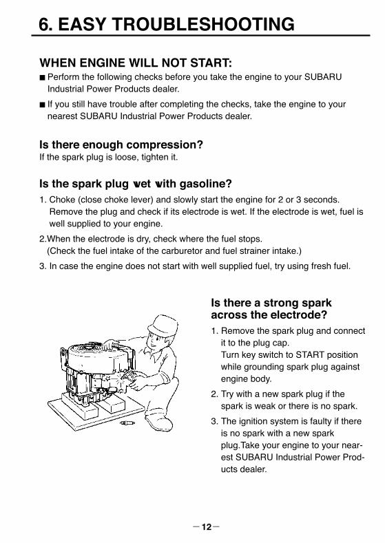
Is there a strong sparkacross the electrode?1. Remove the spark plug and connect
it to the plug cap.Turn key switch to START positionwhile grounding spark plug againstengine body.
2. Try with a new spark plug if thespark is weak or there is no spark.
3. The ignition system is faulty if thereis no spark with a new sparkplug.Take your engine to your near-est SUBARU Industrial Power Prod-ucts dealer.
EH65V_us_EU7285 11.12.19 2:07 PM ページ12

-13-
Is your battery well charged ?If your battery for the electric starter isoverly discharged, your engine will notstart.
Consult your nearest dealer or serviceshop.
WARNINGWipe out spilled fuel carefully before checking.Place spark plug as far away from spark plug hole as possible.Do not hold spark plug by hand while checking.
EH65V_us_EU7285 11.12.19 2:07 PM ページ13

7. SPARK ARRESTER (OPTIONAL)
-14-
SPARK ARRESTERIn a dry or wooded area, it is recommendable to use the product with a sparkarrester. Some areas require the use of a spark arrester. Please check your locallaws and regulations before operating your product.
The spark arrester must be cleaned regularly to keep it functioning as designed. A clogged spark arrester :
● Prevents the flow of exhaust gas ● Reduces engine output ● Increases fuel consumption●Makes starting difficult
How to remove the spark arrester1. Remove the flange bolts from the
muffler cover and remove the mufflercover.
2. Remove the special screw from thespark arrester and remove the sparkarrester from the muffler.
DEFLECTOR
SPARK ARRESTER
MUFFLERCOVER
MUFFLER
Clean the spark arrester screenUse a brush to remove carbon depositsfrom the spark arrester screen.Be careful to avoid damaging the screen.
The spark arrester must be free ofbreaks and holes. Replace the sparkarrester if it is damaged.
Install the spark arrester, and mufflerprotector in the reverse order of disassembly.
SPARK ARRESTER SCREEN
If the engine has been running, the muffler and the spark arrester will be very hot.Allow the muffler to cool before cleaning the spark arrester.
[CAUTION]
EH65V_us_EU7285 11.12.19 2:07 PM ページ14

8. MAINTENANCE SCHEDULE
-15-
Excessive vibration,noise
Clean air cleaner element
Safe surroundings
Enough clean engine oil
Leakage of gasoline and engine oil
Loose or broken bolts and nuts
Enough gasoline
DAILY INSPECTIONBefore running the engine, check the following service items.
PERIODIC MAINTENANCEPeriodic maintenance is vital to safe and efficient operation of your engine.Check the table below for periodic maintenance intervals.
IT IS ALSO NECESSARY FOR THE USER OF THIS ENGINE TO CONDUCTTHE MAINTENANCE AND ADJUSTMENTS ON THE EMISSION-RELATEDPARTS LISTED BELOW TO KEEP THE EMISSION CONTROL SYSTEMEFFECTIVE.
The emission control system consists of the following parts:
The maintenance schedule indicated in the following table is based on the normalengine operation. Should the engine be operated in extremely dusty condition or inheavier loading condition, the maintenance intervals must be shortened dependingon the contamination of oil, clogging of filter elements, wear of parts, and so on.
(1) Carburetor and internalparts
(2) Cold start enrichmentsystem, if applicable
(3) Intake manifold, ifapplicable
(4) Air cleaner elements
(5) Spark plug
(6) Magneto or electronicignition system
(7) Spark advance/retardsystem, if applicable
(8) Exhaust manifold, ifapplicable
(9) Hoses, belts, connec-tors, and assemblies
MAINTENANCE, REPLACEMENT, OR REPAIR OF EMISSION CONTROL DEVICESAND SYSTEMS MAY BE PERFORMED BY ANY NONROAD ENGINE REPAIRESTABLISHMENT OR INDIVIDUAL.
EH65V_us_EU7285 11.12.19 2:07 PM ページ15

-16-
Maintenance ItemsEvery 8hours(Daily)
Every200
hours
Every500
hours
Every1000hours
Clean engine and check bolts and nuts ● (Daily)
Check for leakage from hoses and fitting ● (Daily)
Change engine oil (*Note 1) ●(Initial 20 hours)
Check battery electrolyte fluid level
Clean spark plug
Clean air cleaner
Clean fuel strainer ●
Replace air cleaner element ●
Clean and adjust spark plug and electrodes ●
Replace engine oil filter (*Note 1) ●(Initial 20 hours) ●
Clean and adjust carburetor ●
Remove carbon from cylinder head ●
Every 50
hours
●
●
●
Clean engine base (oil pan) ●
Check and adjust valve clearance ●
Replace spark plug ●
Replace fuel lines ●(Every 2 years)
Overhaul engine (*Note 2) ●
Spark arrester (optional part)
●
●
Periodic Maintenance Schedule table
*Note 1 : Initial oil change and oil filter replacement should be performed after 20 hours ofoperation.Thereafter change oil every hundred (100) hours and replace oil filter 200 hours.Before changing oil, check for a suitable way to dispose of old oil. Do not pour itdown into sewage drains, onto garden soil or into open streams. Your local zoningor environmental regulations will give you more detailed instructions on properdisposal.
*Note 2 : As to the procedures, please refer to the Service Manual or consult your nearestservice dealer.
*Note 3 : More frequent oil changing, oil filter replacement and air cleaner service onreplacement may be necessary depending on operating conditions.This would include dusty environment, high ambient temperature, heavy engineloading.
Check and refill engine oil ●
(Every 100 hours)
(Refill daily to upper level)
(Every 100 hours)
EH65V_us_EU7285 11.12.19 2:07 PM ページ16

9. "HOW-TOW" MAINTENANCE
-17-
INSPECTING THE SPARKPLUG■ Clean off carbon deposits on the
spark plug electrode using a plugcleaner or wire brush.
■ Check electrode gap.Adjust gap to : 0.03 inches(0.7mm to 0.8mm)
■ Use a proper spark plug :BP6ES : NGK (N9YC : CHAMPION)
0.03 in(0.7 to 0.8 mm)
ENGINE OIL CHANGE■ Initial oil change・・・・・After 20 hours of operation
■ Thereafter・・・・・Every 100 hours of operation
1. When changing oil, stop the engineand loosen the drain plug.
2. Re-install the drain plug before refill-ing oil.
3. Refer to the recommended oil tableon page 5.
4. Always use the best grade and cleanoil. Contaminated oil, poor quality oiland shortage of oil cause damage toengine or shorten the engine life.
OIL CAPACITY : 2.0 L
Oil drain plug
EH65V_us_EU7285 11.12.19 2:07 PM ページ17

-18-
ENGINE OIL FILTERREPLACEMENT■ Initial engine oil filter replacement
should be performed after 20 hoursof operation. Thereafter replace theengine oil filter every 200 hours.
■When installing new engine oil filter,apply oil to O-ring, attach the oil filterin position and tighten 3/4 turns byhand or with wrench after touchingthe O-ring to the sealing surface ofengine.
■ After engine running for a while,make sure to check no oil leakagearound the oil filter.
CLEANING AIR CLEANERDirty air cleaner element will causestarting difficulty, power loss, enginemalfunctions, and shorten engine lifeextremely.Keep the air cleaner element alwaysclean.
Air cleaner paper element andurethane form can be take out afterremoving knob and air cleaner cover.When installing, set the paper elementand urethane form on the air cleanerbase. Be sure to check the grommet isin position, and then install the coverwith knob tightened securely.
■ Urethane Form cleaning Wash and clean the urethane form inkerosene. Saturate in a mixture of 3parts kerosene and 1 part engine oil,and then squeeze to remove excessoil. Clean urethane form every 50hours.
Oil filter
Air cleaner cover
Knob
CAUTIONTo prevent injury, pay attentionto the spilled hot engine oilwhen replacing engine oil filter.
GrommetElement
Urethane foam
Base
EH65V_us_EU7285 11.12.19 2:07 PM ページ18

-19-
■ Paper elementClean by tapping gently to removedirt and blow off dust. Never use oil.Clean paper element every 50 hoursof operation, and replace elementevery 200 hours.
CHECKING BOLTS, NUTSAND SCREWSRetighten loose bolts and nuts. Check for fuel and oil leaks. Replace damaged parts with new ones.Keep safety in your mind.
CLEAN COOLING SYSTEMGrass, chaff or dirt may clog the rorat-ing screen and the air cooling systemafter prolonged service.
Before each use check the rotatingscreen and clean grass and debris ifnecessary.
Yearly or every 100 hours, whicheveroccurs first, remove the rotatingscreen, blower housing, cylinder baffleand head cover and clean the coolingfins to avoid overheating and enginedamage.
Keep areas clear of all debris.
EH65V_us_EU7285 11.12.19 2:07 PM ページ19

-20-
CHECKING BATTERY
WARNINGBattery electrolyte is poisonousand acid.Serious injury results from contactwith the skin, eyes or clothing.
If the electrolyte fluid is below level line,refill battery with distilled water.
FUEL HOSE REPLACEMENT
Replace the fuel hose every 1,000hours or every 2 years.If fuel hose leak is found, replace thefuel hose immediately.
WARNINGTake extreme caution when replac-ing fuel hose ; gasoline is flamma-ble.
HIGH ALTITUDE ENGINE OPERATION■ Please have an authorized SUBARU Industrial Power Products dealer modify
this engine if it is to be run continuously above 5,000 feet (1,500 meters). Failure to do so,may result in poor engine performance, spark plug fouling, hard starting, andincreased emissions.
■ Carburetor modification by an authorized SUBARU Industrial Power Productsdealer will improve performance and allow that this engine meets EPA (Environ-mental Protection Agency) and California ARB (Air Resources Board) emission standards throughout its useful life.
■ An engine converted for high altitudes can not be run at 5,000 feet or lower.In doing so, the engine will overheat and cause serious engine damage.Please have an authorized SUBARU Industrial Power Products dealer restorehigh altitude modified engines to the original factory specification before operat-ing below 5,000 feet.
EH65V_us_EU7285 11.12.19 2:07 PM ページ20

10. PREPARATIONS FOR STORAGE
-21-
ENGINE OIL■ Change the engine oil with fresh oil.
■ Remove the spark plug, pour about 5cc of engine oil into the cylinder,slowly start the engine for 2 or 3seconds, and re-install the sparkplug.
CLEAN AND STORE■ Slowly turn the crankshaft until resis-
tance is felt and leave it in that posi-tion.
■ Clean the engine thoroughly with anoiled cloth, put the cover on, andstore the engine indoors in a well-ventilated, low humidity area.
DISCHARGE FUEL (NO SMOKING !)
Drain fuel from fuel tanks, carburetorand fuel line.
WARNINGTake extreme caution when drain-ing ; gasoline is flammable.
EH65V_us_EU7285 11.12.19 2:07 PM ページ21

11. SPECIFICATIONS
-22-
MODEL EH63V EH65V
TypeAir-Cooled, 4-Stroke, V-Twin Cylinder,
Vertical P.T.O. shaft, OHV Gasoline Engine
Bore x stroke 2-80 mm x 65 mm (31.5 in x 25.6 in)
Displacement 653 cm3 (39.8 cu in.)
Maximum Output kW (HP) / rpm
13.4 (18.0) / 3600 16.4 (22.0) / 3600
Max. Torque N・m (kgf・m)/ rpm 43.3 (4.41) / 2000 45.6 (4.65) / 2500
Direction of Rotation Counterclockwise as viewed from P.T.O. shaft side
LubricantAutomotive Engine Oil SAE #20, #30 or 10W-30 ;
Class SE or higher (SG, SH or SJ is recommended)
Capacity of Lubricant 2.0 L (0.41 U.S. gal.)
Fuel Automotive Unleaded Gasoline
Spark plug NGK BP6ES (Champion N9YC)
Starting System Electric Starter
Dry Weight 44 kg (97.0 lb.)
Dimension (L x W x H) 386 mm x 513 mm x 531 mm (15.2 in x 20.2 in x 20.9 in)
Valve Clearance (Intake & Exhaust)
0.0039 ± 0.0012 in (0.1 ± 0.03 mm)Note : Adjust the valve clearance while the engine is cold.
Emissions Durability Period -
• Specifications are subject to change without notice
1000 hours
EH65V_us_EU7285 11.12.19 2:07 PM ページ22

2ZZ9020155
ISSUE EMD-EU7285
OHV Gasoline Engines
EH63V/65V
PRINTED IN JAPANDecember 2011