ehci v1.1 addendum - intel...ehci v1.1 addendum august 2008 8 usb 2.0 bit description 27:24...
TRANSCRIPT

EHCI v1.1 Addendum August 2008
USB 2.0 1
EHCI v1.1 Addendum Energy-efficiency extensions for the EHCI Specification
August 2008
Authors: Barnes Cooper (Intel Corporation)
Paul Diefenbaugh (Intel Corporation)
Bruce Fleming (Intel Corporation)
John Howard (Intel Corporation)
Karthi Vadivelu (Intel Corporation)

EHCI v1.1 Addendum August 2008
2 USB 2.0
NO LICENSE, EXPRESS OR IMPLIED, BY ESTOPPEL OR OTHERWISE, TO ANY INTELLECTUAL PROPERTY RIGHTS IS GRANTED BY THIS DOCUMENT. CONTACT INTEL ON FURTHER LICENSING AGREEMENTS AND REQUIREMENTS. IF YOU HAVE EXECUTED ENHANCED HOST CONTROLLER INTERFACE SPECIFICATION FOR UNIVERSAL SERIAL BUS (USB 2.0) ADOPTER’S AGREEMENT, YOUR LICENSE TO THIS ADDENDUM IS PURSUANT TO THE TERMS OF THE ADOPTER’S AGREEMENT. INTEL ASSUMES NO LIABILITY WHATSOEVER, AND INTEL DISCLAIMS ANY EXPRESS OR IMPLIED WARRANTY, RELATING TO SALE AND/OR USE OF INTEL PRODUCTS INCLUDING LIABILITY OR WARRANTIES RELATING TO FITNESS FOR A PARTICULAR PURPOSE, MERCHANTABILITY, OR INFRINGEMENT OF ANY PATENT, COPYRIGHT OR OTHER INTELLECTUAL PROPERTY RIGHT. UNLESS OTHERWISE AGREED IN WRITING BY INTEL, THE INFORMATION IN THIS DOCUMENT IS NOT DESIGNED NOR INTENDED FOR ANY APPLICATION IN WHICH THE FAILURE OF SUCH APPLICATION COULD CREATE A SITUATION WHERE PERSONAL INJURY OR DEATH MAY OCCUR. Intel may make changes to specifications and product descriptions at any time, without notice. Designers must not rely on the absence or characteristics of any features or instructions marked "reserved" or "undefined." Intel reserves these for future definition and shall have no responsibility whatsoever for conflicts or incompatibilities arising from future changes to them. The information here is subject to change without notice. Do not finalize a design with this information. Contact [email protected] for more information. *Other names and brands may be claimed as the property of others. Copyright © 2008, Intel Corporation. All rights reserved.

EHCI v1.1 Addendum August 2008
USB 2.0 3
Related Documents
Title, Version, Author(s)
Enhanced Host Controller Interface (EHCI) v1.0 Specification, Intel Corporation
USB 2.0 Link Power Management Addendum to the Universal Serial Bus v2.0 Specification, USB-IF

EHCI v1.1 Addendum August 2008
4 USB 2.0
TABLE OF CONTENTS
1. OVERVIEW ....................................................................................................... 5
2. REGISTER INTERFACE CHANGES ............................................................... 6

EHCI v1.1 Addendum August 2008
USB 2.0 5
1. Overview This addendum is intended to define several energy efficiency extensions for USB 2.0 host controller
implementations based on the Enhance Host Controller Interface (EHCI) Specification, most notably:
● Hardware Prefetching: Ability for host controller hardware to safely prefetch information from the
asynchronous and periodic schedules beyond what was defined in previous EHCI implementations to
improve system memory access behavior. This is achieved by defining mechanisms whereby system
software strictly coordinates changes to the asynchronous and periodic schedule structures with hardware.
● Link Power Management: Defines the mechanisms by which software can discover and use Link Power
Management (LPM) support to be offered by next-generation EHCI host controllers and USB devices. The
implementation leverages much of the existing Suspend/Resume infrastructure to streamline software
support for this key energy efficiency feature.
● Per-Port Change Events: Addresses an issue where system software is currently required to read and parse
the port status registers (PORTSC) for all enabled root ports upon every port change event (interrupt). This
is particularly important as LPM state transitions will be exposed to software as port change events, noting
the software overhead combined with the potential increase in event frequency could negatively impact OS
responsiveness and system-level energy efficiency.
● Shorter Periodic Frame List: Ability for system software to convey and use a much shorter periodic frame
list (32 frames) to better facilitate Hardware Prefetching.
Chapter 2 details changes to the Register Interface section of the EHCI v1.0 specification where changes to the
existing interface are clearly identified (highlighted in this color).

EHCI v1.1 Addendum August 2008
6 USB 2.0
2. Register Interface Changes
:
2.2.2 HCIVERSION Host Controller Interface Version Number
Address: Base+ (02h) Default Value: 0110h Attribute RO Size: 16 bits
This is a two-byte register containing a BCD encoding of the EHCI revision number supported by this host
controller. The most significant byte of this register represents a major revision and the least significant byte
is the minor revision. Version 1.1 is defined by this addendum.
:
2.2.4 HCCPARAMS Capability Parameters
Address: Base+ (08h) Default Value Implementation Dependent Attribute RO Size: 32 bits
Multiple Mode control (time-base bit functionality), addressing capability
Table 2-1. HCCPARAMSHost Controller Capability Parameters
Bit Description
31:20 Reserved. These bits are reserved and should be set to zero.
19 32-Frame Periodic List Capability. Default = Implementation dependent. When set (1b) this optional field indicates the host controller supports a 32 frame periodic schedule as specified by using the value 11b in the USBCMD Frame List Size field. Software must treat a Frame List Size value of 11b as reserved when this bit is cleared (0b). Note that support for other programmable Frame List Size values (01b = 512 frames, 10b = 256 frames) continues to be indicated through the Programmable Frame List Flag, where this bit only indicates programmability for a 32-frame list.
18 Per-Port Change Event Capability. Default = Implementation dependent. When set (1b) this optional field indicates host controller support for per-port change events and associated USBCMD Per-Port Change Event Enable, USBSTS Port-n Change Detect, and USBINT Port-n Change Interrupt Enable fields. Note that software should treat those fields as reserved when this bit is cleared (0b).
17 Link Power Management Capability. Default = Implementation dependent. When set (1b) this optional field indicates host controller support for the Link Power Management L1 state and associated PORTSC Suspend using L1, Suspend Status, and Device Address fields. Note that software should treat those fields as reserved when this bit is cleared (0b).
16 Hardware Prefetch Capability. Default = Implementation dependent. When set (1b) this optional field indicates the host controller supports the Hardware Prefetching capability and associated USBCMD Fully Synchronized Prefetch, Periodic Schedule Prefetch Enable, and Asynchronous Schedule Prefetch Enable fields. Note that software should treat those fields as reserved when this bit is cleared (0b).
15:8 EHCI Extended Capabilities Pointer (EECP). Default = Implementation Dependent. This optional field indicates the existence of a capabilities list. A value of 00h indicates no extended capabilities are implemented. A non-zero value in this register indicates the offset in PCI configuration space of the first EHCI extended capability. The pointer value must be 40h or greater if implemented to maintain the consistency of the PCI header defined for this class of device.

EHCI v1.1 Addendum August 2008
USB 2.0 7
Bit Description
7:4 Isochronous Scheduling Threshold. Default = implementation dependent. This field indicates, relative to the current position of the executing host controller, where software can reliably update the isochronous schedule. When bit [7] is zero, the value of the least significant 3 bits indicates the number of micro-frames a host controller can hold a set of isochronous data structures (one or more) before flushing the state. When bit [7] is a one, then host software assumes the host controller may cache an isochronous data structure for an entire frame. Refer to Section 4.7.2.1 for details on how software uses this information for scheduling isochronous transfers.
3 Reserved. This bit is reserved and should be set to zero.
2 Asynchronous Schedule Park Capability. Default = Implementation dependent. If this bit is set to a one, then the host controller supports the park feature for high-speed queue heads in the Asynchronous Schedule. The feature can be disabled or enabled and set to a specific level by using the Asynchronous Schedule Park Mode Enable and Asynchronous Schedule Park Mode Count fields in the USBCMD register.
1 Programmable Frame List Flag. Default = Implementation dependent. If this bit is set to a zero, then system software must use a frame list length of 1024 elements with this host controller. The USBCMD register Frame List Size field is a read-only register and should be set to zero.
If set to a one, then system software can specify and use a smaller frame list and configure the host controller via the USBCMD register Frame List Size field. The frame list must always be aligned on a 4K page boundary. This requirement ensures that the frame list is always physically contiguous.
0 64-bit Addressing Capability1. This field documents the addressing range capability of
this implementation. The value of this field determines whether software should use the data structures defined in Section 3 (32-bit) or those defined in Appendix B (64-bit). Values for this field have the following interpretation:
0b data structures using 32-bit address memory pointers 1b data structures using 64-bit address memory pointers
[1] This is not tightly coupled with the USBBASE address register mapping control. The 64-bit Addressing
Capability bit indicates whether the host controller can generate 64-bit addresses as a master. The USBBASE
register indicates the host controller only needs to decode 32-bit addresses as a slave.
:
2.3.1 USBCMD USB Command Register
Address: Operational Base+ (00h) Default Value: 00080000h (00080B00h if Asynchronous Schedule Park Capability is a one) Attribute RO, R/W (field dependent), WO Size 32 bits
The Command Register indicates the command to be executed by the serial bus host controller. Writing to
the register causes a command to be executed.
Table 2-2. USBCMD – USB Command Register Bit Definitions
Bit Description
31:28 Reserved. These bits are reserved and should be set to zero.
EHCI v1.1 Addendum August 2008
8 USB 2.0
Bit Description
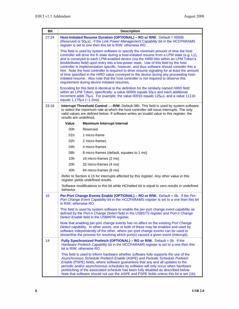
27:24 Host-Initiated Resume Duration (OPTIONAL) – RO or R/W. Default = 0000b (Reserved or 50s). If the Link Power Management Capability bit in the HCCPARAMS register is set to one then this bit is R/W; otherwise RO.
This field is used by system software to specify the minimum amount of time the host controller will drive the K-state during a host-initiated resume from a LPM state (e.g. L1), and is conveyed to each LPM-enabled device (via the HIRD bits within an LPM Token’s bmAttributes field) upon entry into a low-power state. Use of this field by the host controller is implementation specific, however, and thus software should consider this a hint. Note the host controller is required to drive resume signaling for at least the amount of time specified in the HIRD value conveyed to the device during any proceeding host-initiated resume. Also note that the host controller is not required to observe this requirement during device-initiated resumes.
Encoding for this field is identical to the definition for the similarly named HIRD field within an LPM Token, specifically: a value 0000b equals 50s and each additional increment adds 75s. For example, the value 0001b equals 125s, and a value 1111b equals 1,175s (~1.2ms).
23:16 Interrupt Threshold Control R/W. Default 08h. This field is used by system software to select the maximum rate at which the host controller will issue interrupts. The only valid values are defined below. If software writes an invalid value to this register, the results are undefined.
Value Maximum Interrupt Interval
00h Reserved
01h 1 micro-frame
02h 2 micro-frames
04h 4 micro-frames
08h 8 micro-frames (default, equates to 1 ms)
10h 16 micro-frames (2 ms)
20h 32 micro-frames (4 ms)
40h 64 micro-frames (8 ms)
Refer to Section 4.15 for interrupts affected by this register. Any other value in this register yields undefined results.
Software modifications to this bit while HCHalted bit is equal to zero results in undefined behavior.
15 Per-Port Change Events Enable (OPTIONAL) – RO or R/W. Default = 0b. If the Per-Port Change Event Capability bit in the HCCPARAMS register is set to a one then this bit is R/W; otherwise RO.
This field is used by system software to enable the per-port change event capability as defined by the Port-n Change Detect field in the USBSTS register and Port-n Change Detect Enable field in the USBINTR register.
Note that enabling per-port change events has no affect on the existing Port Change Detect capability. In other words, one or both of these may be enabled and used by software independently of the other, where per-port change events can be used to streamline the process for resolving which port(s) caused a given event (interrupt).
14 Fully Synchronized Prefetch (OPTIONAL) – RO or R/W. Default = 0b. If the Hardware Prefetch Capability bit in the HCCPARAMS register is set to a one then this bit is R/W; otherwise RO.
This field is used to inform hardware whether software fully supports the use of the Asynchronous Schedule Prefetch Enable (ASPE) and Periodic Schedule Prefetch Enable (PSPE) fields, where software guarantees that any and all updates to the periodic and/or asynchronous schedules by software will only occur when hardware prefetching of the associated schedule has been fully disabled as described below. Note that software should not use the ASPE and PSPE fields unless this bit is set (1b).

EHCI v1.1 Addendum August 2008
USB 2.0 9
Bit Description
13 Asynchronous Schedule Prefetch Enable (OPTIONAL) – RO or R/W. Default = 0b. If the Hardware Prefetch Capability bit in the HCCPARAMS register is set to a one then this bit is R/W; otherwise RO. This bit should only be used by software – and thereby only set – when the Fully Synchronized Prefetch bit is enabled.
Software sets this bit (1b) to enable hardware prefetching of the asynchronous schedule. Hardware prefetching must be disabled before software applies any changes to the asynchronous schedule or structures linked to this schedule. To disable hardware prefetching software must first write a 0b and then wait until a read of this field returns 0b – noting the host controller must return a value of 1b until hardware prefetching of the asynchronous schedule has been safely disabled. Software re-enables hardware prefetching by writing a 1b to this bit once all updates to the asynchronous schedule have been applied. Note that hardware prefetching of the periodic schedule may remain active when software is solely modifying the asynchronous schedule.
12 Periodic Schedule Prefetch Enable (OPTIONAL) – RO or R/W. Default = 0b. If the Hardware Prefetch Capability bit in the HCCPARAMS register is set (1b) then this bit is R/W; otherwise RO. This bit should only be used by software – and thereby only set – when the Fully Synchronized Prefetch bit is enabled.
Software sets this bit (1b) to enable hardware prefetching of the periodic schedule. Hardware prefetching must be disabled before software applies any changes to the periodic schedule or structures linked to this schedule. To disable hardware prefetching software must first write a 0b and then wait until a read of this field returns 0b – noting the host controller must return a value of 1b until hardware prefetching of the periodic schedule has been safely disabled. Software re-enables hardware prefetching by writing a 1b to this bit once all updates to the periodic schedule have been applied. Note that hardware prefetching of the asynchronous schedule may remain active when software is solely modifying the periodic schedule.
11 Asynchronous Schedule Park Mode Enable (OPTIONAL) RO or R/W. If the Asynchronous Park Capability bit in the HCCPARAMS register is a one, then this bit defaults to a 1h and is R/W. Otherwise the bit must be a zero and is RO. Software uses this bit to enable or disable Park mode. When this bit is one, Park mode is enabled. When this bit is a zero, Park mode is disabled.
10 Reserved. This bit is reserved and should be set to zero.
9:8 Asynchronous Schedule Park Mode Count (OPTIONAL) RO or R/W. If the Asynchronous Park Capability bit in the HCCPARAMS register is a one, then this field defaults to 3h and is R/W. Otherwise it defaults to zero and is RO. It contains a count of the number of successive transactions the host controller is allowed to execute from a high-speed queue head on the Asynchronous schedule before continuing traversal of the Asynchronous schedule. See Section 4.10.3.2 for full operational details. Valid values are 1h to 3h. Software must not write a zero to this bit when Park Mode Enable is a one as this will result in undefined behavior.
7 Light Host Controller Reset (OPTIONAL) R/W. This control bit is not required. If implemented, it allows the driver to reset the EHCI controller without affecting the state of the ports or the relationship to the companion host controllers. For example, the PORSTC registers should not be reset to their default values and the CF bit setting should not go to zero (retaining port ownership relationships).
A host software read of this bit as zero indicates the Light Host Controller Reset has completed and it is safe for host software to re-initialize the host controller. A host software read of this bit as a one indicates the Light Host Controller Reset has not yet completed.
If not implemented a read of this field will always return a zero.
EHCI v1.1 Addendum August 2008
10 USB 2.0
Bit Description
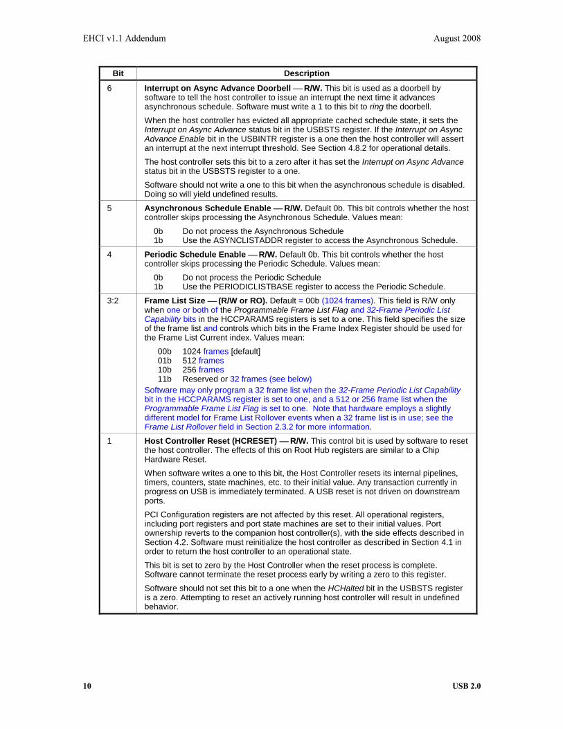
6 Interrupt on Async Advance Doorbell R/W. This bit is used as a doorbell by software to tell the host controller to issue an interrupt the next time it advances asynchronous schedule. Software must write a 1 to this bit to ring the doorbell.
When the host controller has evicted all appropriate cached schedule state, it sets the Interrupt on Async Advance status bit in the USBSTS register. If the Interrupt on Async Advance Enable bit in the USBINTR register is a one then the host controller will assert an interrupt at the next interrupt threshold. See Section 4.8.2 for operational details.
The host controller sets this bit to a zero after it has set the Interrupt on Async Advance status bit in the USBSTS register to a one.
Software should not write a one to this bit when the asynchronous schedule is disabled. Doing so will yield undefined results.
5 Asynchronous Schedule Enable R/W. Default 0b. This bit controls whether the host controller skips processing the Asynchronous Schedule. Values mean:
0b Do not process the Asynchronous Schedule 1b Use the ASYNCLISTADDR register to access the Asynchronous Schedule.
4 Periodic Schedule Enable R/W. Default 0b. This bit controls whether the host controller skips processing the Periodic Schedule. Values mean:
0b Do not process the Periodic Schedule 1b Use the PERIODICLISTBASE register to access the Periodic Schedule.
3:2 Frame List Size (R/W or RO). Default = 00b (1024 frames). This field is R/W only when one or both of the Programmable Frame List Flag and 32-Frame Periodic List Capability bits in the HCCPARAMS registers is set to a one. This field specifies the size of the frame list and controls which bits in the Frame Index Register should be used for the Frame List Current index. Values mean:
00b 1024 frames [default] 01b 512 frames 10b 256 frames 11b Reserved or 32 frames (see below)
Software may only program a 32 frame list when the 32-Frame Periodic List Capability bit in the HCCPARAMS register is set to one, and a 512 or 256 frame list when the Programmable Frame List Flag is set to one. Note that hardware employs a slightly different model for Frame List Rollover events when a 32 frame list is in use; see the Frame List Rollover field in Section 2.3.2 for more information.
1 Host Controller Reset (HCRESET) R/W. This control bit is used by software to reset the host controller. The effects of this on Root Hub registers are similar to a Chip Hardware Reset.
When software writes a one to this bit, the Host Controller resets its internal pipelines, timers, counters, state machines, etc. to their initial value. Any transaction currently in progress on USB is immediately terminated. A USB reset is not driven on downstream ports.
PCI Configuration registers are not affected by this reset. All operational registers, including port registers and port state machines are set to their initial values. Port ownership reverts to the companion host controller(s), with the side effects described in Section 4.2. Software must reinitialize the host controller as described in Section 4.1 in order to return the host controller to an operational state.
This bit is set to zero by the Host Controller when the reset process is complete. Software cannot terminate the reset process early by writing a zero to this register.
Software should not set this bit to a one when the HCHalted bit in the USBSTS register is a zero. Attempting to reset an actively running host controller will result in undefined behavior.

EHCI v1.1 Addendum August 2008
USB 2.0 11
Bit Description
0 Run/Stop (RS) R/W. Default 0b. 1=Run. 0=Stop. When set to a 1, the Host Controller proceeds with execution of the schedule. The Host Controller continues execution as long as this bit is set to a 1. When this bit is set to 0, the Host Controller completes the current and any actively pipelined transactions on the USB and then halts. The Host Controller must halt within 16 micro-frames after software clears the Run bit. The HC Halted bit in the status register indicates when the Host Controller has finished its pending pipelined transactions and has entered the stopped state. Software must not write a one to this field unless the host controller is in the Halted state (i.e. HCHalted in the USBSTS register is a one). Doing so will yield undefined results.
:
2.3.2 USBSTS USB Status Register
Address: Operational Base + (04h) Default Value: 00001000h Attribute RO, R/W, R/WC, (field dependent) Size 32 bits
This register indicates pending interrupts and various states of the Host Controller. The status resulting from
a transaction on the serial bus is not indicated in this register. Software sets a bit to 0 in this register by
writing a 1 to it. See Section 4.15 for additional information concerning USB interrupt conditions.
Table 2-3. USBSTS USB Status Register Bit Definitions
Bit Description
31:16 Port-n Change Detect – RO or R/WC. If the Per-Port Change Event Capability bit in the HCCPARAMS register is set to a one then this field is R/WC; otherwise RO. This field should only be used by software when the Per-Port Change Events Enable bit within the USBCMD register is set to a one.
The definition for each bit is identical to the Port Change Detect field (bit 2 of this register) except these bits are specific to a given port, where bit 16 = Port 1, 17 = Port 2, etc. For example, if bit 17 is set to a one then a port change event was detected on Port 2. The N_PORTS field in HCSPARAMS specifies how many ports are exposed by the host controller and thus how many bits in this field are valid.
Hardware must preserve the behavior of the Port Change Detect and related fields even when Per-Port Change Events are enabled, noting software may choose to employ one or both of these capabilities.
15 Asynchronous Schedule Status RO. 0=Default. The bit reports the current real status of the Asynchronous Schedule. If this bit is a zero then the status of the Asynchronous Schedule is disabled. If this bit is a one then the status of the Asynchronous Schedule is enabled. The Host Controller is not required to immediately disable or enable the Asynchronous Schedule when software transitions the Asynchronous Schedule Enable bit in the USBCMD register. When this bit and the Asynchronous Schedule Enable bit are the same value, the Asynchronous Schedule is either enabled (1) or disabled (0).
14 Periodic Schedule Status RO. 0=Default. The bit reports the current real status of the Periodic Schedule. If this bit is a zero then the status of the Periodic Schedule is disabled. If this bit is a one then the status of the Periodic Schedule is enabled. The Host Controller is not required to immediately disable or enable the Periodic Schedule when software transitions the Periodic Schedule Enable bit in the USBCMD register. When this bit and the Periodic Schedule Enable bit are the same value, the Periodic Schedule is either enabled (1) or disabled (0).
13 Reclamation RO. 0=Default. This is a read-only status bit, which is used to detect an empty asynchronous schedule. The operational model of empty schedule detection is described in Section 4.8.3. The valid transitions for this bit are described in Section 4.8.6.

EHCI v1.1 Addendum August 2008
12 USB 2.0
Bit Description
12 HCHalted RO. 1=Default. This bit is a zero whenever the Run/Stop bit is a one. The Host Controller sets this bit to one after it has stopped executing as a result of the Run/Stop bit being set to 0, either by software or by the Host Controller hardware (e.g. internal error).
11:6 Reserved. These bits are reserved and should be set to zero.
5 Interrupt on Async Advance R/WC. 0=Default. System software can force the host controller to issue an interrupt the next time the host controller advances the asynchronous schedule by writing a one to the Interrupt on Async Advance Doorbell bit in the USBCMD register. This status bit indicates the assertion of that interrupt source.
4 Host System Error R/WC. The Host Controller sets this bit to 1 when a serious error occurs during a host system access involving the Host Controller module. In a PCI system, conditions that set this bit to 1 include PCI Parity error, PCI Master Abort, and PCI Target Abort. When this error occurs, the Host Controller clears the Run/Stop bit in the Command register to prevent further execution of the scheduled TDs.
3 Frame List Rollover R/WC. The host controller sets this bit to a one when a frame list rollover event occurs. The exact Frame List Index value at which the rollover occurs depends on the frame list size, noting this generally occurs when FRINDEX rolls over from its maximum value to zero. For example, if the frame list size (as programmed in the Frame List Size field of the USBCMD register) is 1024 then a frame list rollover would occur every time FRINDEX[13] toggles. Similarly, a frame list rollover event would occur every time FRINDEX[12] toggles for a 512 frame list, and when FRINDEX[11] toggles for a 256 frame list. Note this behavior is different for a 32 frame list where a rollover event occurs every time FRINDEX[13] toggles (same as 1024).
2 Port Change Detect R/WC. The Host Controller sets this bit to a one when any port for which the Port Owner bit is set to zero has a change bit transition from a zero to a one or a Force Port Resume bit transition from a zero to a one as a result of a J-K transition detected on a suspended port. This bit will also be set as a result of the Connect Status Change being set to a one after system software has relinquished ownership of a connected port by writing a one to a port's Port Owner bit (see Section 4.2.2).
This bit is allowed to be maintained in the Auxiliary power well. Alternatively, it is also acceptable that on a D3 to D0 transition of the EHCI HC device, this bit is loaded with the OR of all of the PORTSC change bits (including: Force port resume, over-current change, enable/disable change and connect status change).
1 USB Error Interrupt (USBERRINT) R/WC. The Host Controller sets this bit to 1 when completion of a USB transaction results in an error condition (e.g., error counter underflow). If the TD on which the error interrupt occurred also had its IOC bit set, both this bit and USBINT bit are set. See Section 4.15.1 for a list of the USB errors that will result in this bit being set to a one.
0 USB Interrupt (USBINT) R/WC. The Host Controller sets this bit to 1 on the completion of a USB transaction, which results in the retirement of a Transfer Descriptor that had its IOC bit set.
The Host Controller also sets this bit to 1 when a short packet is detected (actual number of bytes received was less than the expected number of bytes).
:

EHCI v1.1 Addendum August 2008
USB 2.0 13
2.3.3 USBINTR USB Interrupt Enable Register
Address: Operational Base + (08h) Default Value: 00000000h Attributes R/W Size 32 bits
This register enables and disables reporting of the corresponding interrupt to the software. When a bit is set
and the corresponding interrupt is active, an interrupt is generated to the host. Interrupt sources that are
disabled in this register still appear in the USBSTS to allow the software to poll for events.
Each interrupt enable bit description indicates whether it is dependent on the interrupt threshold mechanism
(see Section 4.15).
Table 2-4. USBINTR - USB Interrupt Enable Register
Bit Interrupt Source Description
31:16 Port-n Change Event Enable The definition for each bit in this field is identical to bit 2 of this register (Port Change Interrupt Enable) except these bits are specific to a given port, where bit 16 = Port 1, 17 = Port 2, etc. For example, if bit 17 is set (1b) then a port change event was detected on Port 2. When a bit in this field is a one, and the corresponding Port-n Change Detect bit in the USBSTS register is a one, the host controller will issue an interrupt. The interrupt is acknowledged by software clearing the Port-n Change Detect bit.
15:6 Reserved These bits are reserved and should be zero.
5 Interrupt on Async Advance Enable When this bit is a one, and the Interrupt on Async Advance bit in the USBSTS register is a one, the host controller will issue an interrupt at the next interrupt threshold. The interrupt is acknowledged by software clearing the Interrupt on Async Advance bit.
4 Host System Error Enable When this bit is a one, and the Host System Error Status bit in the USBSTS register is a one, the host controller will issue an interrupt. The interrupt is acknowledged by software clearing the Host System Error bit.
3 Frame List Rollover Enable When this bit is a one, and the Frame List Rollover bit in the USBSTS register is a one, the host controller will issue an interrupt. The interrupt is acknowledged by software clearing the Frame List Rollover bit.
2 Port Change Interrupt Enable When this bit is a one, and the Port Change Detect bit in the USBSTS register is a one, the host controller will issue an interrupt. The interrupt is acknowledged by software clearing the Port Change Detect bit.
1 USB Error Interrupt Enable When this bit is a one, and the USBERRINT bit in the USBSTS register is a one, the host controller will issue an interrupt at the next interrupt threshold. The interrupt is acknowledged by software clearing the USBERRINT bit.

EHCI v1.1 Addendum August 2008
14 USB 2.0
Bit Interrupt Source Description
0 USB Interrupt Enable When this bit is a one, and the USBINT bit in the USBSTS register is a one, the host controller will issue an interrupt at the next interrupt threshold. The interrupt is acknowledged by software clearing the USBINT bit.
Note: for all enable register bits, 1= Enabled, 0= Disabled
:
2.3.4 FRINDEX Frame Index Register
Address: Operational Base + (0Ch) Default Value: 00000000h Attribute: R/W (Writes must be DWord Writes) Size 32 bits
This register is used by the host controller to index into the periodic frame list. The register updates every
125 microseconds (once each micro-frame). Bits [N:3] are used to select a particular entry in the Periodic
Frame List during periodic schedule execution. The number of bits used for the index depends on the size of
the frame list as set by system software in the Frame List Size field in the USBCMD register (see Table 2-2).
This register must be written as a DWord. Byte writes produce undefined results. This register cannot be
written unless the Host Controller is in the Halted state as indicated by the HCHalted bit (USBSTS register
Section 2.3.2). A write to this register while the Run/Stop bit is set to a one (USBCMD register, Section
2.3.1) produces undefined results. Writes to this register also affect the SOF value. See Section 4.5 for
details.
Table 2-5. FRINDEX Frame Index Register
Bit Description
31:14 Reserved.
13:0 Frame Index. The value in this register increments at the end of each time frame (e.g. micro-frame). Bits [N:3] are used for the Frame List Current Index. This means that each location of the frame list is accessed 8 times (frames or micro-frames) before moving to the next index. The following illustrates values of N based on the value of the Frame List Size field in the USBCMD register.
USBCMD[Frame List Size] Number Elements N
00b 1024 12 01b 512 11 10b 256 10 11b 32 12
† (see below)
The SOF frame number value for the bus SOF token is derived or alternatively managed from this register.
Please refer to Section 4.5 for a detailed explanation of the SOF value management requirements on the host
controller. The value of FRINDEX must be 125 sec (1 micro-frame) ahead of the SOF token value. The
SOF value may be implemented as an 11-bit shadow register. For this discussion, this shadow register is 11
bits and is named SOFV. SOFV updates every 8 micro-frames. (1 millisecond). An example implementation
to achieve this behavior is to increment SOFV each time the FRINDEX[2:0] increments from a zero to a
one.
Software must use the value of FRINDEX to derive the current micro-frame number, both for high-speed
isochronous scheduling purposes and to provide the get micro-frame number function required for client
drivers. Therefore, the value of FRINDEX and the value of SOFV must be kept consistent if chip is reset or
software writes to FRINDEX. Writes to FRINDEX must also write-through FRINDEX[13:3] to

EHCI v1.1 Addendum August 2008
USB 2.0 15
SOFV[10:0]. In order to keep the update as simple as possible, software should never write a FRINDEX
value where the three least significant bits are 111b or 000b. Please refer to Section 4.5.
The host controller behaves slightly different when using a 32-frame Frame List Size, specifically it
continues to count FRINDEX up to a full 1024 frames, transmit SOF values from 0 to 2047, and generate
Frame List Rollover events (when enabled) every 1024 frames – exactly as if a 1024 frame list size was
employed. The host controller will only reference 32 elements on the periodic schedule, however. This is
accomplished by formulating the Periodic Frame List Element Address using {FRINDEX[N:3] modulo 32}
rather than FRINDEX[N:3]. The same mapping should be done by system software whenever it needs to
correlate the current FRINDEX value to a specific periodic schedule element. Note this new behavior only
applies to a 32-frame list.
:
2.3.4 PORTSC Port Status and Control Register
Address: Operational Base + (44h + (4*Port Number-1)) where: Port Number is 1, 2, 3, … N_PORTS
Default: 00002000h (w/PPC set to one); 00003000h (w/PPC set to a zero) Attribute: RO, R/W, R/WC (field dependent) Size 32 bits
A host controller must implement one or more port registers. The number of port registers implemented by a
particular instantiation of a host controller is documented in the HCSPARAMs register (Section 2.2.3).
Software uses this information as an input parameter to determine how many ports need to be serviced. All
ports have the structure defined below.
This register is in the auxiliary power well. It is only reset by hardware when the auxiliary power is initially
applied or in response to a host controller reset. The initial conditions of a port are:
No device connected,
Port disabled
If the port has port power control, software cannot change the state of the port until after it applies power to
the port by setting port power to a 1. Software must not attempt to change the state of the port until after
power is stable on the port. The host is required to have power stable to the port within 20 milliseconds of
the zero to one transition.
Note1: When a device is attached, the port state transitions to the connected state and system software will
process this as with any status change notification. Refer to Section 4.3 for operational requirements for how
change events interact with port suspend mode.
Note2: If a port is being used as the Debug Port, then the port may report device connected and enabled
when the Configured Flag is a zero.
Table 2-6. PORTSC Port Status and Control
Bit Description
31:25 Device Address – RO or R/W. Default = 0000000b. The 7-bit USB device address for the device attached to and immediately downstream of the associated root port. A value of zero indicates no device is present or support for this feature is not present.

EHCI v1.1 Addendum August 2008
16 USB 2.0
Bit Description
24:23 Suspend Status – RO. Default = 00b. These two bits are used by software to determine whether the most recent L1 suspend request was successful, specifically:
Value Meaning 00b Success: State transition was successful (ACK) 01b Not Yet: Device was unable to enter the L1 state at this time (NYET) 10b Not Supported: Device does not support the L1 state (STALL) 11b Timeout/Error: Device failed to respond or an error occurred
This field is updated by hardware immediately following the completion of an L1 transition request (via an LPM Token). To avoid any race conditions with hardware, software should only consume the contents of this field when Suspend = 0b (port no longer in L1).
22 Wake on Over-current Enable (WKOC_E) R/W. Default = 0b. Writing this bit to a one enables the port to be sensitive to over-current conditions as wake-up events. See Section 4.3 for effects of this bit on resume event behavior. Refer to Section 4.31 for operational model.
This field is zero if Port Power is zero.
21 Wake on Disconnect Enable (WKDSCNNT_E) R/W. Default = 0b. Writing this bit to a one enables the port to be sensitive to device disconnects as wake-up events. See Section 4.3 for effects of this bit on resume event behavior. Refer to Section 4.31 for operational model.
This field is zero if Port Power is zero.
20 Wake on Connect Enable (WKCNNT_E) R/W. Default = 0b. Writing this bit to a one enables the port to be sensitive to device connects as wake-up events. See Section 4.3 for effects of this bit on resume event behavior. Refer to Section 4.31 for operational model.
This field is zero if Port Power is zero.
19:16 Port Test ControlR/W. Default = 0000b. When this field is zero, the port is NOT operating in a test mode. A non-zero value indicates that it is operating in test mode and the specific test mode is indicated by the specific value. The encoding of the test mode bits are (0110b - 1111b are reserved):
Bits Test Mode
0000b Test mode not enabled 0001b Test J_STATE 0010b Test K_STATE 0011b Test SE0_NAK 0100b Test Packet 0101b Test FORCE_ENABLE
Refer to Section 4.14 for the operational model for using these test modes and the USB Specification Revision 2.0, Chapter 7 for details on each test mode.
15:14 Port Indicator Control. Default = 00b. Writing to these bits has no effect if the P_INDICATOR bit in the HCSPARAMS register is a zero. If P_INDICATOR bit is a one, then the bit encodings are:
Bit Value Meaning
00b Port indicators are off 01b Amber 10b Green 11b Undefined
Refer to the USB Specification Revision 2.0 for a description on how these bits are to be used.
This field is zero if Port Power is zero.

EHCI v1.1 Addendum August 2008
USB 2.0 17
Bit Description
13 Port OwnerR/W Default = 1b. This bit unconditionally goes to a 0b when the Configured bit in the CONFIGFLAG register makes a 0b to 1b transition. This bit unconditionally goes to 1b whenever the Configured bit is zero.
System software uses this field to release ownership of the port to a selected host controller (in the event that the attached device is not a high-speed device). Software writes a one to this bit when the attached device is not a high-speed device. A one in this bit means that a companion host controller owns and controls the port. See Section 4.2 for operational details.
12 Port Power (PP)R/W or RO. The function of this bit depends on the value of the Port Power Control (PPC) field in the HCSPARAMS register. The behavior is as follows:
PPC PP Operation
0b 1b ROHost controller does not have port power control switches. Each port is hard-wired to power.
1b 1b/0b R/WHost controller has port power control switches. This bit represents the current setting of the switch (0 = off, 1 = on). When power is not available on a port (i.e. PP equals a 0), the port is non-functional and will not report attaches, detaches, etc.
When an over-current condition is detected on a powered port and PPC is a one, the PP bit in each affected port may be transitioned by the host controller from a 1 to 0 (removing power from the port).
11:10 Line StatusRO. These bits reflect the current logical levels of the D+ (bit 11) and D- (bit 10) signal lines. These bits are used for detection of low-speed USB devices prior to the port reset and enable sequence. This field is valid only when the port enable bit is zero and the current connect status bit is set to a one.
The encoding of the bits are:
Bits[11:10] USB State Interpretation
00b SE0 Not Low-speed device, perform EHCI reset 10b J-state Not Low-speed device, perform EHCI reset 01b K-state Low-speed device, release ownership of port 11b Undefined Not Low-speed device, perform EHCI reset.
This value of this field is undefined if Port Power is zero.
9 Suspend using L1 – R/W. Default = 0b. 0b = Suspend using L2; 1b = Suspend using L1 (LPM). When this bit is set to a one and a non-zero value is specified in the Device Address field the host controller will generate an LPM Token to enter the L1 state whenever software writes a one to the Suspend bit, as well as L1 exit timing during any device- or host-initiated resume. When set to zero the host controller will employ the legacy (L2) suspend mechanism. Software should only set this bit when the device attached immediately downstream of this root port supports L1 transitions.

EHCI v1.1 Addendum August 2008
18 USB 2.0
Bit Description
8 Port ResetR/W. 1=Port is in Reset. 0=Port is not in Reset. Default = 0. When software writes a one to this bit (from a zero), the bus reset sequence as defined in the USB Specification Revision 2.0 is started. Software writes a zero to this bit to terminate the bus reset sequence. Software must keep this bit at a one long enough to ensure the reset sequence, as specified in the USB Specification Revision 2.0, completes. Note: when software writes this bit to a one, it must also write a zero to the Port Enable bit.
Note that when software writes a zero to this bit there may be a delay before the bit status changes to a zero. The bit status will not read as a zero until after the reset has completed. If the port is in high-speed mode after reset is complete, the host controller will automatically enable this port (e.g. set the Port Enable bit to a one). A host controller must terminate the reset and stabilize the state of the port within 2 milliseconds of software transitioning this bit from a one to a zero. For example: if the port detects that the attached device is high-speed during reset, then the host controller must have the port in the enabled state within 2ms of software writing this bit to a zero.
The HCHalted bit in the USBSTS register should be a zero before software attempts to use this bit. The host controller may hold Port Reset asserted to a one when the HCHalted bit is a one.
This field is zero if Port Power is zero.
7 Suspend R/W. 1 = Port in suspend state. 0 = Port not in suspend state. Default = 0. The Port Enabled/Disabled and Suspend bits of this register define the port state as follows:
Bits [Port Enabled, Suspend] Port State 0X Disable 10 Enable 11 Suspend
Software writes a one to this bit to transition a port to either the L1 or L2 suspend state. Which suspend state the host controller attempts depends on the value of the Suspend Using L1 field. When in the suspend state, downstream propagation of data is blocked on this port, except for port reset. If this bit is set to a one when a transaction is in progress then the blocking will not occur until the end of the current transaction. In the suspend state, the port is sensitive to resume detection. Note that the status of this bit does not change until the port is fully suspended and there may be a delay in suspending a port if a transaction is currently in progress on the USB. Addition status for L1-based transitions is provided to software via the Suspend Status field.
A write of zero to this bit is ignored by the host controller. The host controller will unconditionally set this bit to a zero when:
Software sets the Force Port Resume bit to a zero (from a one).
Software sets the Port Reset bit to a one (from a zero).
Whenever Port Power is zero.
If system software sets this bit to a one when the port is not enabled (i.e. Port Enabled/Disabled bit is set to zero) the results are undefined.

EHCI v1.1 Addendum August 2008
USB 2.0 19
Bit Description
6 Force Port Resume R/W. 1= Resume detected/driven on port. 0=No resume (K-state) detected/driven on port. Default = 0. This functionality defined for manipulating this bit depends on the value of the Suspend and Suspend Using L1 bits. For example, if the port is not suspended (Suspend and Enabled bits are a one) and software transitions this bit to a one, then the effects on the bus are undefined.
Software sets this bit to a one to drive resume signaling. The Host Controller sets this bit to a one if a J-to-K transition is detected while the port is in the Suspend state. When this bit transitions to a one because a J-to-K transition is detected, the Port Change Detect and/or Port-n Change Detect bits in the USBSTS register are also set to a one. If software sets this bit to a one, the host controller must not set the Port Change Detect and/or Port-n Change Detect bits.
Note that when the EHCI controller owns the port, the resume sequence follows the defined sequence documented in the USB Specification Revision 2.0. The resume signaling (Full-speed 'K') is driven on the port as long as this bit remains a one. For legacy (L2) transitions, software must appropriately time the resume and set this bit to a zero when the appropriate amount of time has elapsed. Writing a zero (from one) causes the port to return to high-speed mode (forcing the bus below the port into a high-speed idle). This bit will remain a one until the port has switched to the high-speed idle. The host controller must complete this transition within 2 milliseconds of software setting this bit to a zero. Software does not need to time resume signaling for L1 transactions as host controller hardware will automatically enforce the necessary timing and clear this bit when the port has fully resumed. Software can influence the amount of time hardware will drive resume signaling during L1 exit via the Host-Initiated Resume Duration field within the USBCMD register.
This field is zero if Port Power is zero.
5 Over-current Change R/WC. Default = 0. 1=This bit gets set to a one when there is a change to Over-current Active. Software clears this bit by writing a one to this bit position.
4 Over-current Active RO. Default = 0. 1=This port currently has an over-current condition. 0=This port does not have an over-current condition. This bit will automatically transition from a one to a zero when the over current condition is removed.
3 Port Enable/Disable ChangeR/WC. 1=Port enabled/disabled status has changed. 0=No change. Default = 0. For the root hub, this bit gets set to a one only when a port is disabled due to the appropriate conditions existing at the EOF2 point (See Chapter 11 of the USB Specification for the definition of a Port Error). Software clears this bit by writing a 1 to it.
This field is zero if Port Power is zero.
2 Port Enabled/DisabledR/W. 1=Enable. 0=Disable. Default = 0. Ports can only be enabled by the host controller as a part of the reset and enable. Software cannot enable a port by writing a one to this field. The host controller will only set this bit to a one when the reset sequence determines that the attached device is a high-speed device.
Ports can be disabled by either a fault condition (disconnect event or other fault condition) or by host software. Note that the bit status does not change until the port state actually changes. There may be a delay in disabling or enabling a port due to other host controller and bus events. See Section 4.2 for full details on port reset and enable.
When the port is disabled (0b) downstream propagation of data is blocked on this port, except for reset.
This field is zero if Port Power is zero.

EHCI v1.1 Addendum August 2008
20 USB 2.0
Bit Description
1 Connect Status ChangeR/WC. 1=Change in Current Connect Status. 0=No change. Default = 0. Indicates a change has occurred in the port’s Current Connect Status. The host controller sets this bit for all changes to the port device connect status, even if system software has not cleared an existing connect status change. For example, the insertion status changes twice before system software has cleared the changed condition, hub hardware will be “setting” an already-set bit (i.e., the bit will remain set). Software sets this bit to 0 by writing a 1 to it.
This field is zero if Port Power is zero.
0 Current Connect StatusRO. 1=Device is present on port. 0=No device is present. Default = 0. This value reflects the current state of the port, and may not correspond directly to the event that caused the Connect Status Change bit (Bit 1) to be set.
This field is zero if Port Power is zero.