eighth edition - apl100apl100.wdfiles.com/local--files/...beer_chapter_07mod-updated.pdf · vector...
TRANSCRIPT
VECTOR MECHANICS FOR ENGINEERS:
STATICS
Eighth Edition
Ferdinand P. Beer
E. Russell Johnston, Jr.
Lecture Notes:
J. Walt Oler
Texas Tech University
CHAPTER
© 2007 The McGraw-Hill Companies, Inc. All rights reserved.
7 Forces in Beams
and Cables
© 2007 The McGraw-Hill Companies, Inc. All rights reserved.
Vector Mechanics for Engineers: Statics
Eig
hth
E
ditio
n
7- 2
Contents
Introduction
Internal Forces in Members
Sample Problem 7.1
Various Types of Beam Loading
and Support
Shear and Bending Moment in a
Beam
Sample Problem 7.2
Sample Problem 7.3
Relations Among Load, Shear,
and Bending Moment
© 2007 The McGraw-Hill Companies, Inc. All rights reserved.
Vector Mechanics for Engineers: Statics
Eig
hth
E
ditio
n
7- 3
Contents
Sample Problem 7.4
Sample Problem 7.6
Cables With
Concentrated Loads
Cables With
Distributed Loads
Parabolic Cable
Sample Problem 7.8
Catenary

© 2007 The McGraw-Hill Companies, Inc. All rights reserved.
Vector Mechanics for Engineers: Statics
Eig
hth
E
ditio
n
7- 4
Introduction
•Preceding chapters dealt with:
a) determining external forces acting on
a structure and
b)determining forces which hold together
the various members of a structure.
© 2007 The McGraw-Hill Companies, Inc. All rights reserved.
Vector Mechanics for Engineers: Statics
Eig
hth
E
ditio
n
7- 5
Introduction
•The current chapter is concerned with
determining the internal forces (i.e.,
tension/compression, shear, and
bending) which hold together the
various parts of a given member.
© 2007 The McGraw-Hill Companies, Inc. All rights reserved.
Vector Mechanics for Engineers: Statics
Eig
hth
E
ditio
n
7- 6
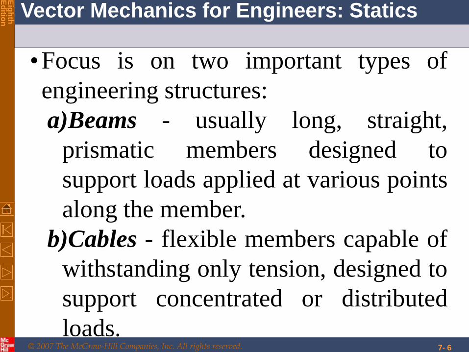
•Focus is on two important types of
engineering structures:
a)Beams - usually long, straight,
prismatic members designed to
support loads applied at various points
along the member.
b)Cables - flexible members capable of
withstanding only tension, designed to
support concentrated or distributed
loads.
© 2007 The McGraw-Hill Companies, Inc. All rights reserved.
Vector Mechanics for Engineers: Statics
Eig
hth
E
ditio
n
7- 7
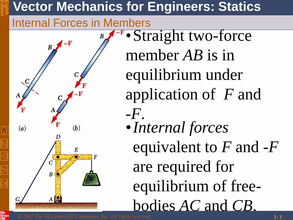
Internal Forces in Members
•Straight two-force
member AB is in
equilibrium under
application of F and
-F. •Internal forces
equivalent to F and -F
are required for
equilibrium of free-
bodies AC and CB.
© 2007 The McGraw-Hill Companies, Inc. All rights reserved.
Vector Mechanics for Engineers: Statics
Eig
hth
E
ditio
n
7- 8
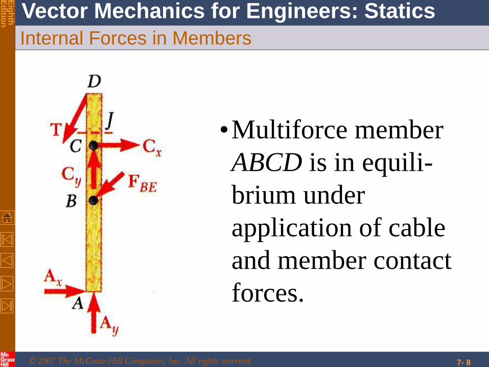
Internal Forces in Members
•Multiforce member
ABCD is in equili-
brium under
application of cable
and member contact
forces.
© 2007 The McGraw-Hill Companies, Inc. All rights reserved.
Vector Mechanics for Engineers: Statics
Eig
hth
E
ditio
n
7- 9
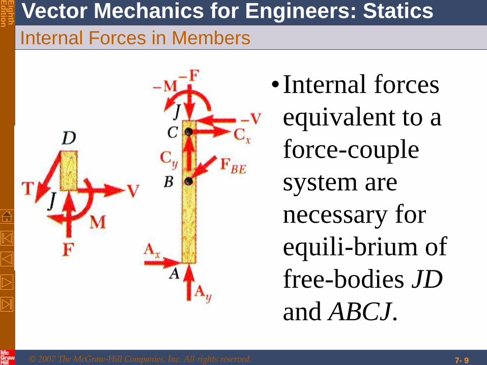
Internal Forces in Members
•Internal forces
equivalent to a
force-couple
system are
necessary for
equili-brium of
free-bodies JD
and ABCJ.
© 2007 The McGraw-Hill Companies, Inc. All rights reserved.
Vector Mechanics for Engineers: Statics
Eig
hth
E
ditio
n
7- 10
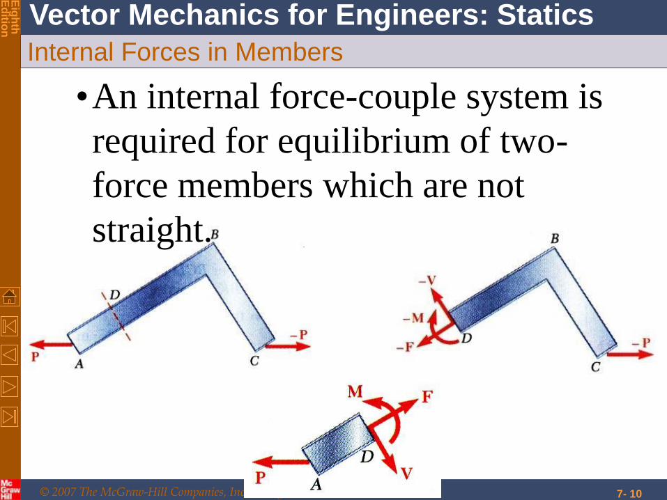
Internal Forces in Members
•An internal force-couple system is
required for equilibrium of two-
force members which are not
straight.

© 2007 The McGraw-Hill Companies, Inc. All rights reserved.
Vector Mechanics for Engineers: Statics
Eig
hth
E
ditio
n
Beams
7- 11
© 2007 The McGraw-Hill Companies, Inc. All rights reserved.
Vector Mechanics for Engineers: Statics
Eig
hth
E
ditio
n
4 - 12
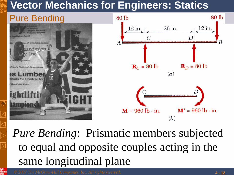
Pure Bending
Pure Bending: Prismatic members subjected
to equal and opposite couples acting in the
same longitudinal plane
© 2007 The McGraw-Hill Companies, Inc. All rights reserved.
Vector Mechanics for Engineers: Statics
Eig
hth
E
ditio
n
4 - 13
© 2007 The McGraw-Hill Companies, Inc. All rights reserved.
Vector Mechanics for Engineers: Statics
Eig
hth
E
ditio
n
7- 14
© 2007 The McGraw-Hill Companies, Inc. All rights reserved.
Vector Mechanics for Engineers: Statics
Eig
hth
E
ditio
n
7- 15

© 2007 The McGraw-Hill Companies, Inc. All rights reserved.
Vector Mechanics for Engineers: Statics
Eig
hth
E
ditio
n
Post and Lintel
7- 16
© 2007 The McGraw-Hill Companies, Inc. All rights reserved.
Vector Mechanics for Engineers: Statics
Eig
hth
E
ditio
n
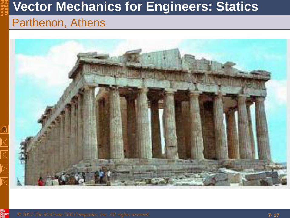
Parthenon, Athens
7- 17

© 2007 The McGraw-Hill Companies, Inc. All rights reserved.
Vector Mechanics for Engineers: Statics
Eig
hth
E
ditio
n
Corbelled domes and vaults
7- 18
© 2007 The McGraw-Hill Companies, Inc. All rights reserved.
Vector Mechanics for Engineers: Statics
Eig
hth
E
ditio
n
7- 19
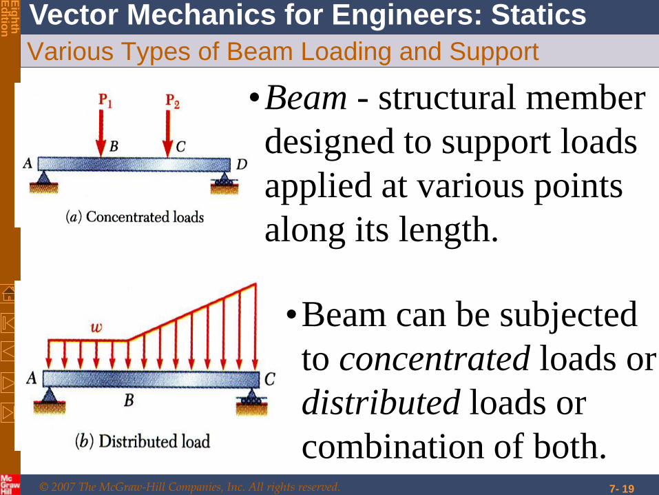
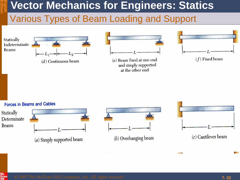
Various Types of Beam Loading and Support
•Beam - structural member
designed to support loads
applied at various points
along its length.
•Beam can be subjected
to concentrated loads or
distributed loads or
combination of both.
© 2007 The McGraw-Hill Companies, Inc. All rights reserved.
Vector Mechanics for Engineers: Statics
Eig
hth
E
ditio
n
7- 20
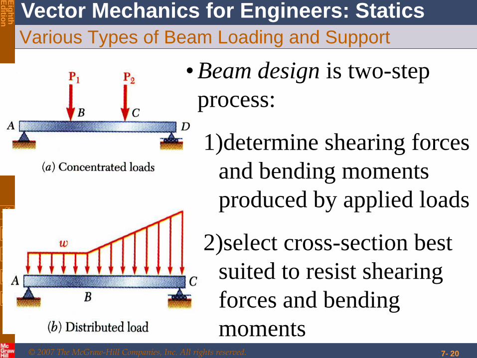
Various Types of Beam Loading and Support
• Beam design is two-step
process:
1)determine shearing forces
and bending moments
produced by applied loads
2)select cross-section best
suited to resist shearing
forces and bending
moments

© 2007 The McGraw-Hill Companies, Inc. All rights reserved.
Vector Mechanics for Engineers: Statics
Eig
hth
E
ditio
n
7- 21
Various Types of Beam Loading and Support
•Beams are classified according to way in
which they are supported.
•Reactions at beam supports are
determinate if they involve only three
unknowns. Otherwise, they are statically
indeterminate.
© 2007 The McGraw-Hill Companies, Inc. All rights reserved.
Vector Mechanics for Engineers: Statics
Eig
hth
E
ditio
n
7- 22
Various Types of Beam Loading and Support
© 2007 The McGraw-Hill Companies, Inc. All rights reserved.
Vector Mechanics for Engineers: Statics
Eig
hth
E
ditio
n
7- 23
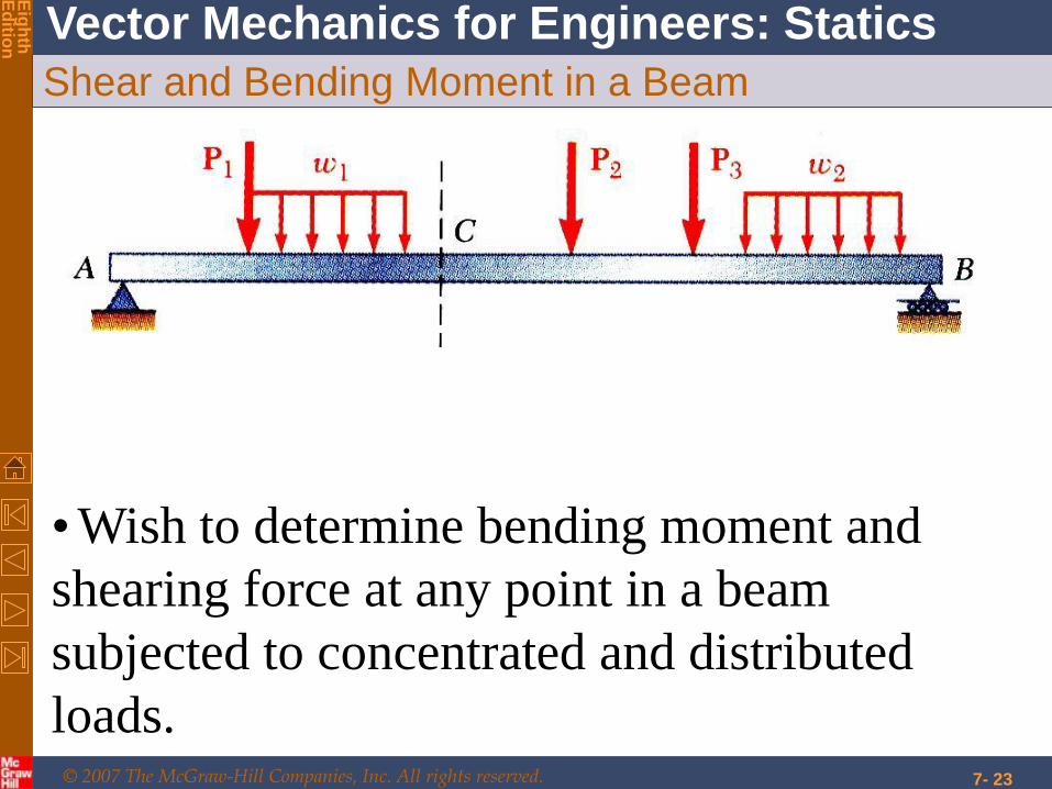
Shear and Bending Moment in a Beam
• Wish to determine bending moment and
shearing force at any point in a beam
subjected to concentrated and distributed
loads.
© 2007 The McGraw-Hill Companies, Inc. All rights reserved.
Vector Mechanics for Engineers: Statics
Eig
hth
E
ditio
n
7- 24
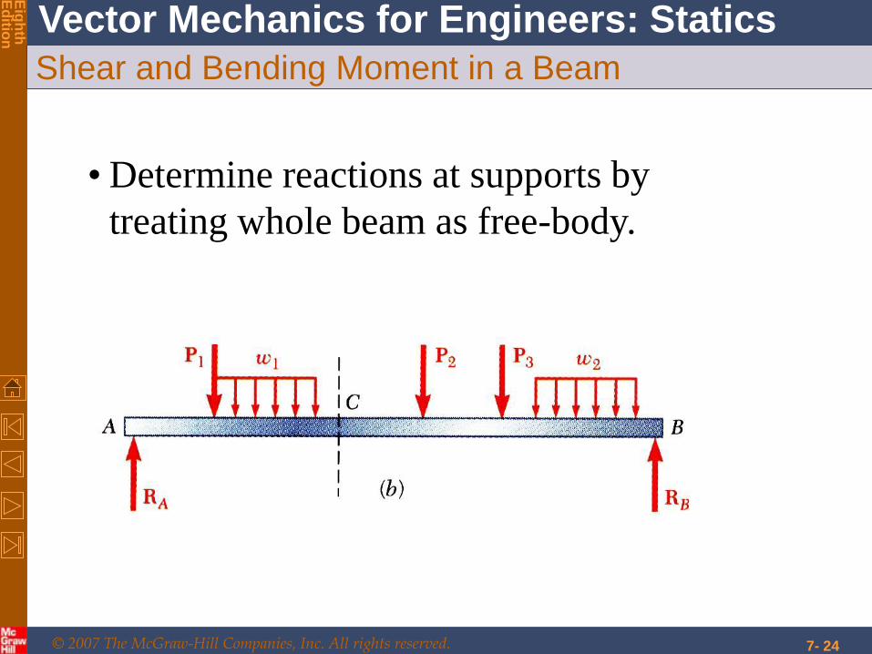
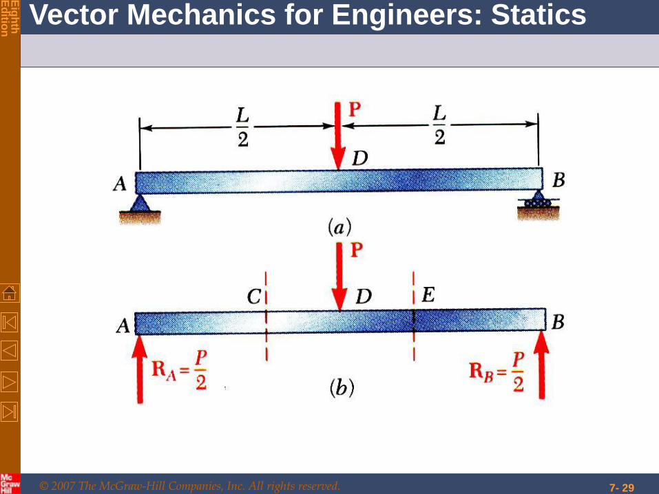
Shear and Bending Moment in a Beam
• Determine reactions at supports by
treating whole beam as free-body.
© 2007 The McGraw-Hill Companies, Inc. All rights reserved.
Vector Mechanics for Engineers: Statics
Eig
hth
E
ditio
n
7- 25
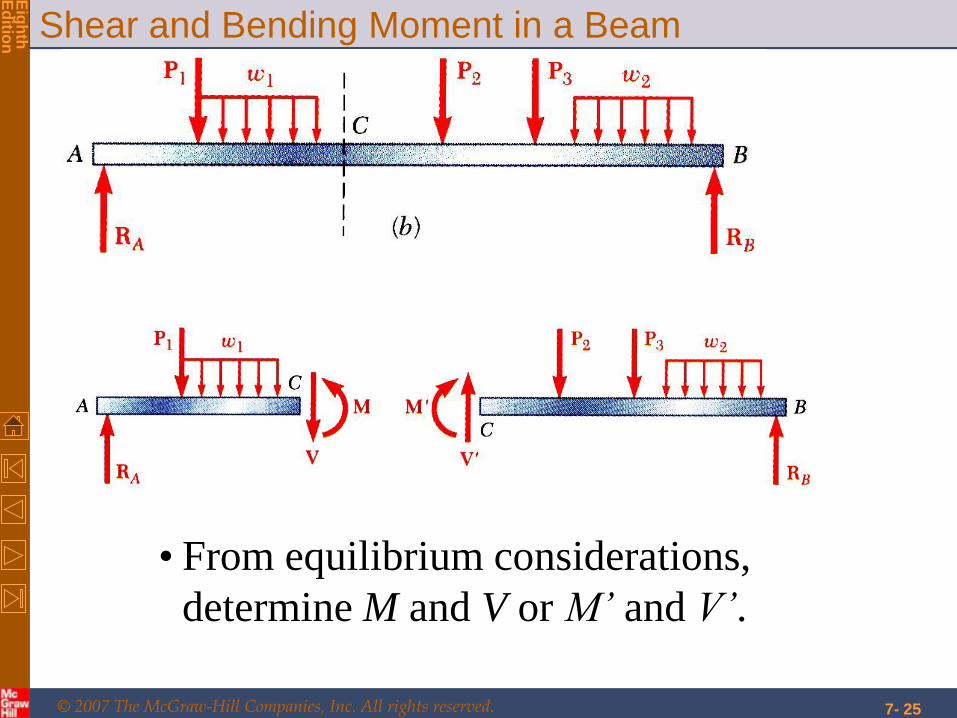
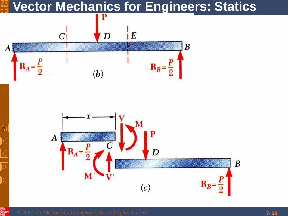
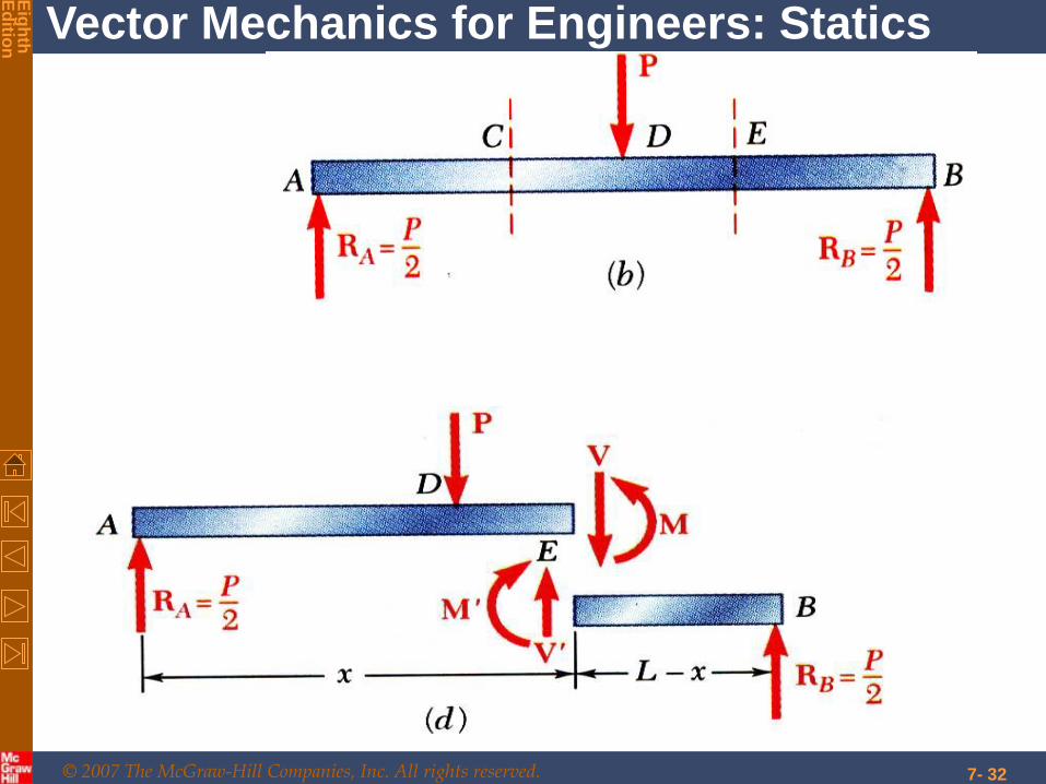
Shear and Bending Moment in a Beam
• From equilibrium considerations,
determine M and V or M’ and V’.

© 2007 The McGraw-Hill Companies, Inc. All rights reserved.
Vector Mechanics for Engineers: Statics
Eig
hth
E
ditio
n
7- 26
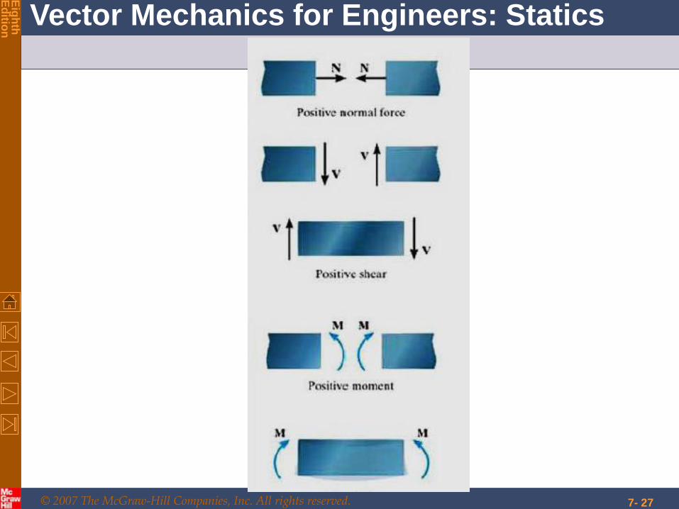
Shear and Bending Moment in a Beam
• Cut beam at C and draw free-body diagrams for AC
and CB. By definition, positive sense for internal
force-couple systems are as shown. This way we
don’t have to specify from which section ( AC or BC)
we are calculating V and M.
© 2007 The McGraw-Hill Companies, Inc. All rights reserved.
Vector Mechanics for Engineers: Statics
Eig
hth
E
ditio
n
7- 27

© 2007 The McGraw-Hill Companies, Inc. All rights reserved.
Vector Mechanics for Engineers: Statics
Eig
hth
E
ditio
n
7- 28
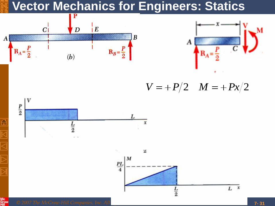
Shear and Bending Moment Diagrams
• Variation of shear and bending moment along
beam may be plotted. • Determine reactions at supports.
© 2007 The McGraw-Hill Companies, Inc. All rights reserved.
Vector Mechanics for Engineers: Statics
Eig
hth
E
ditio
n
7- 29
© 2007 The McGraw-Hill Companies, Inc. All rights reserved.
Vector Mechanics for Engineers: Statics
Eig
hth
E
ditio
n
7- 30
© 2007 The McGraw-Hill Companies, Inc. All rights reserved.
Vector Mechanics for Engineers: Statics
Eig
hth
E
ditio
n
7- 31
22 PxMPV
© 2007 The McGraw-Hill Companies, Inc. All rights reserved.
Vector Mechanics for Engineers: Statics
Eig
hth
E
ditio
n
7- 32
© 2007 The McGraw-Hill Companies, Inc. All rights reserved.
Vector Mechanics for Engineers: Statics
Eig
hth
E
ditio
n
7- 33
22 xLPMPV

© 2007 The McGraw-Hill Companies, Inc. All rights reserved.
Vector Mechanics for Engineers: Statics
Eig
hth
E
ditio
n
7- 34
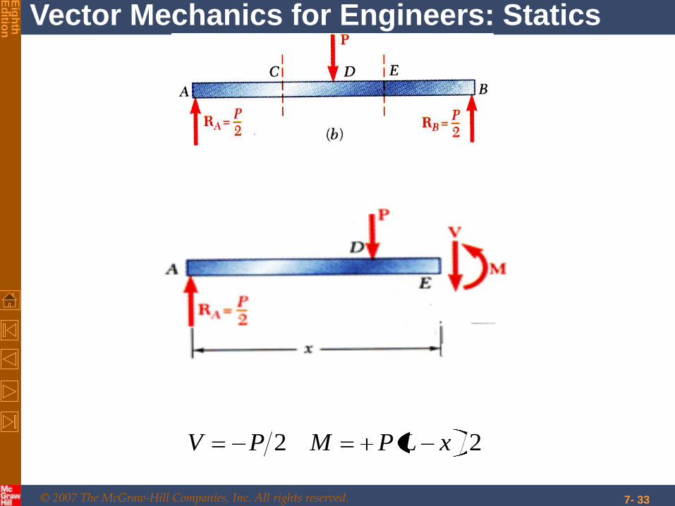
Shear and Bending Moment Diagrams
• Cut beam at E and consider member EB, 22 xLPMPV
• Cut beam at C and consider member AC,
22 PxMPV

© 2007 The McGraw-Hill Companies, Inc. All rights reserved.
Vector Mechanics for Engineers: Statics
Eig
hth
E
ditio
n
7- 35
Shear and Bending Moment Diagrams
© 2007 The McGraw-Hill Companies, Inc. All rights reserved.
Vector Mechanics for Engineers: Statics
Eig
hth
E
ditio
n
7- 36
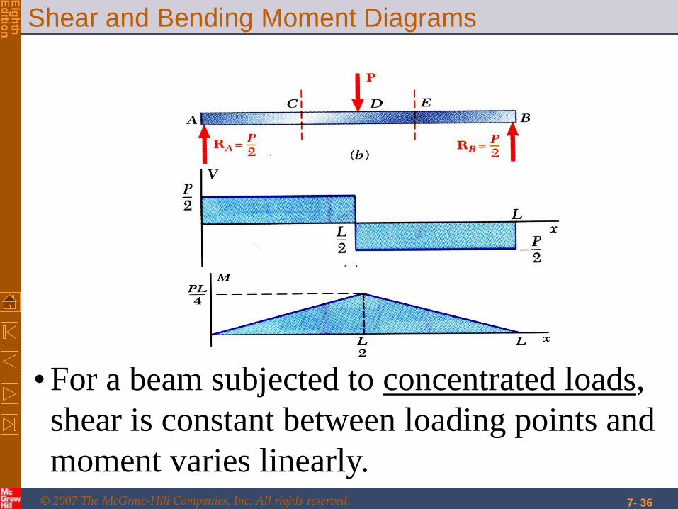
Shear and Bending Moment Diagrams
• For a beam subjected to concentrated loads,
shear is constant between loading points and
moment varies linearly.
© 2007 The McGraw-Hill Companies, Inc. All rights reserved.
Vector Mechanics for Engineers: Statics
Eig
hth
E
ditio
n
7- 37
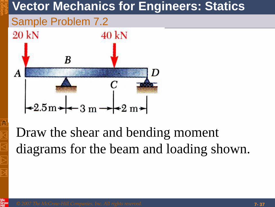
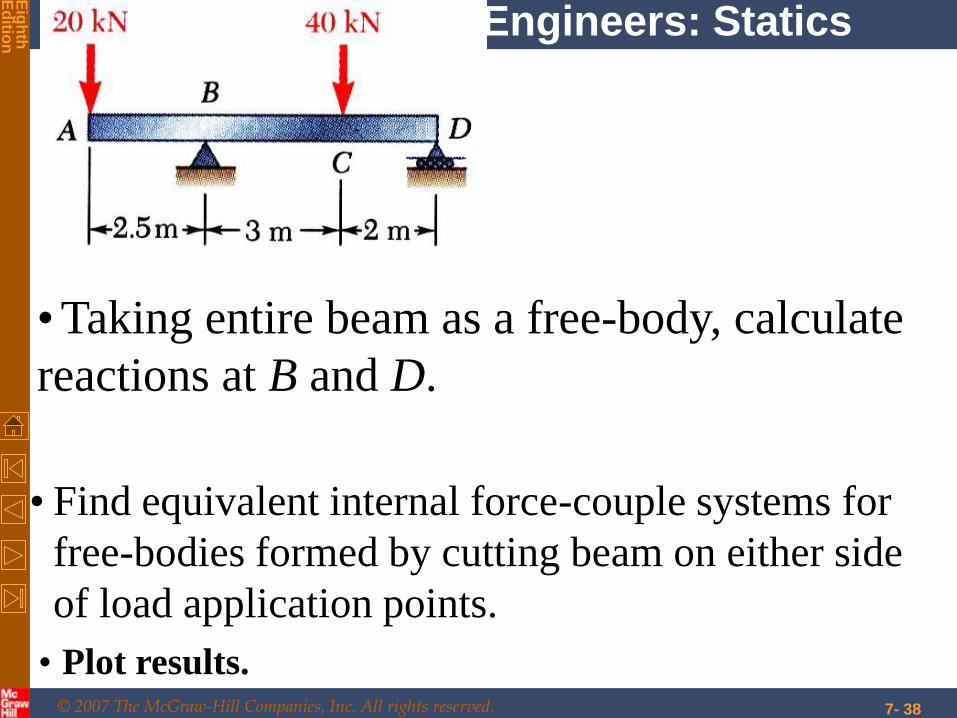
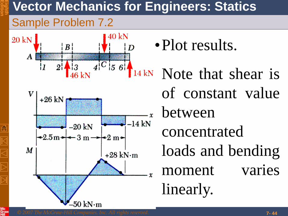
Sample Problem 7.2
Draw the shear and bending moment
diagrams for the beam and loading shown.
© 2007 The McGraw-Hill Companies, Inc. All rights reserved.
Vector Mechanics for Engineers: Statics
Eig
hth
E
ditio
n
7- 38
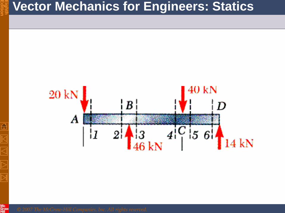
• Taking entire beam as a free-body, calculate
reactions at B and D.
• Find equivalent internal force-couple systems for
free-bodies formed by cutting beam on either side
of load application points.
• Plot results.
© 2007 The McGraw-Hill Companies, Inc. All rights reserved.
Vector Mechanics for Engineers: Statics
Eig
hth
E
ditio
n

© 2007 The McGraw-Hill Companies, Inc. All rights reserved.
Vector Mechanics for Engineers: Statics
Eig
hth
E
ditio
n
:0yF
0kN20 1V kN201V
:01M
0m0kN20 1M 01M
© 2007 The McGraw-Hill Companies, Inc. All rights reserved.
Vector Mechanics for Engineers: Statics
Eig
hth
E
ditio
n
7- 41
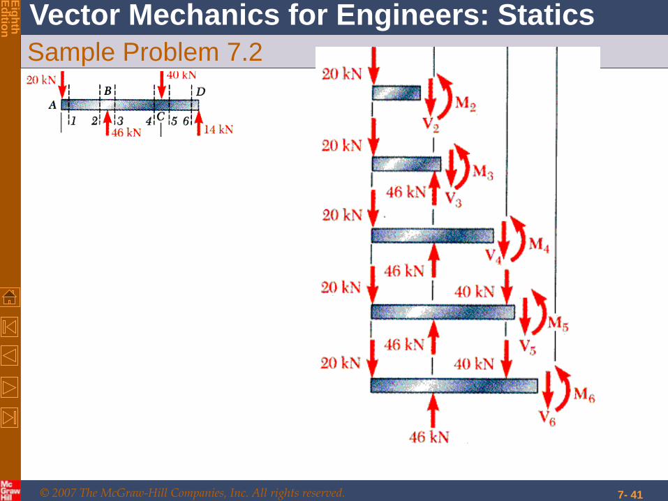
Sample Problem 7.2

© 2007 The McGraw-Hill Companies, Inc. All rights reserved.
Vector Mechanics for Engineers: Statics
Eig
hth
E
ditio
n
Sample Problem 7.2
7- 42
© 2007 The McGraw-Hill Companies, Inc. All rights reserved.
Vector Mechanics for Engineers: Statics
Eig
hth
E
ditio
n
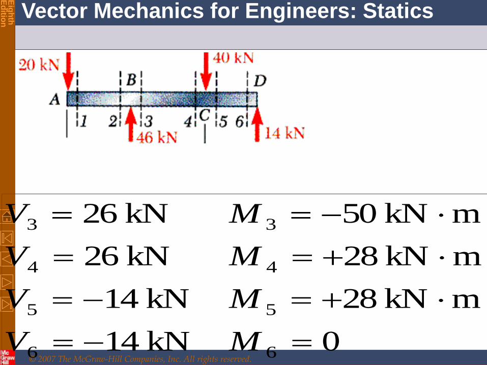
0kN14
mkN28kN14
mkN28kN26
mkN50kN26
66
55
44
33
MV
MV
MV
MV
© 2007 The McGraw-Hill Companies, Inc. All rights reserved.
Vector Mechanics for Engineers: Statics
Eig
hth
E
ditio
n
7- 44
Sample Problem 7.2
•Plot results.
Note that shear is
of constant value
between
concentrated
loads and bending
moment varies
linearly.

© 2007 The McGraw-Hill Companies, Inc. All rights reserved.
Vector Mechanics for Engineers: Statics
Eig
hth
E
ditio
n
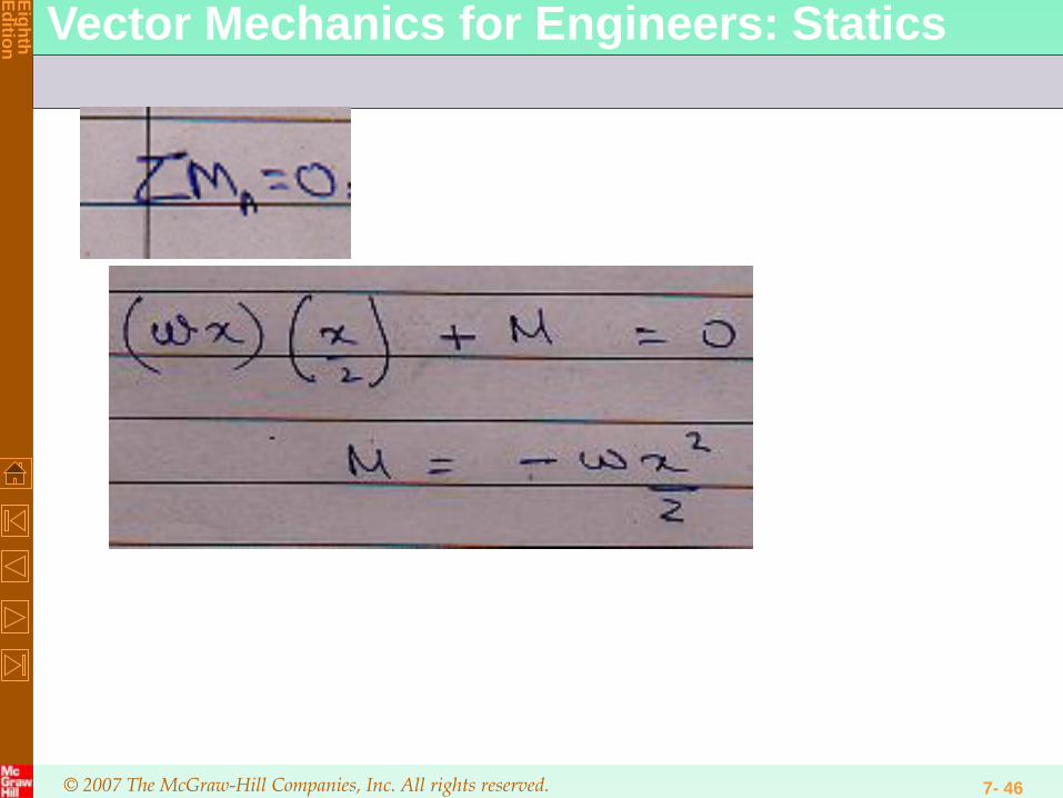
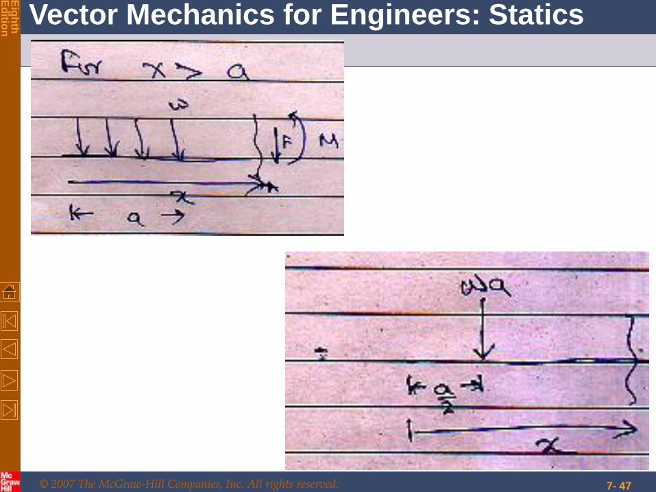
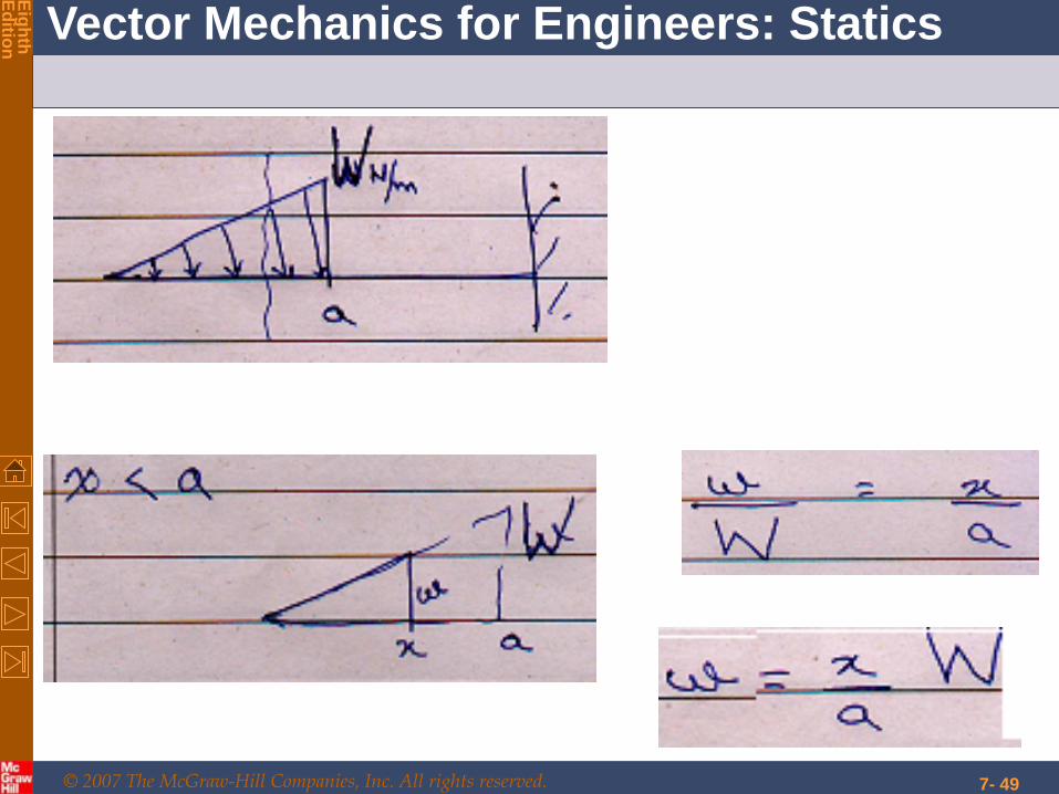
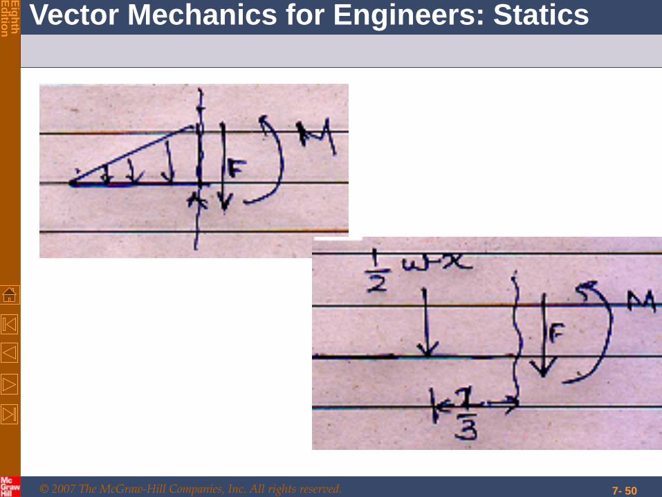
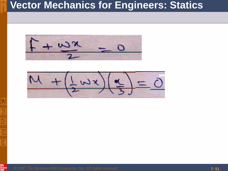
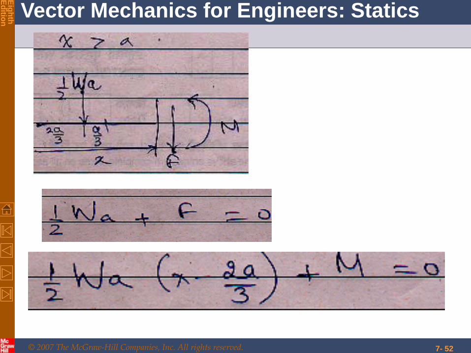
UDL (Uniformly distributed load)
7- 45
© 2007 The McGraw-Hill Companies, Inc. All rights reserved.
Vector Mechanics for Engineers: Statics
Eig
hth
E
ditio
n
7- 46
© 2007 The McGraw-Hill Companies, Inc. All rights reserved.
Vector Mechanics for Engineers: Statics
Eig
hth
E
ditio
n
7- 47

© 2007 The McGraw-Hill Companies, Inc. All rights reserved.
Vector Mechanics for Engineers: Statics
Eig
hth
E
ditio
n
7- 48
© 2007 The McGraw-Hill Companies, Inc. All rights reserved.
Vector Mechanics for Engineers: Statics
Eig
hth
E
ditio
n
7- 49
© 2007 The McGraw-Hill Companies, Inc. All rights reserved.
Vector Mechanics for Engineers: Statics
Eig
hth
E
ditio
n
7- 50
© 2007 The McGraw-Hill Companies, Inc. All rights reserved.
Vector Mechanics for Engineers: Statics
Eig
hth
E
ditio
n
7- 51
© 2007 The McGraw-Hill Companies, Inc. All rights reserved.
Vector Mechanics for Engineers: Statics
Eig
hth
E
ditio
n
7- 52
© 2007 The McGraw-Hill Companies, Inc. All rights reserved.
Vector Mechanics for Engineers: Statics
Eig
hth
E
ditio
n
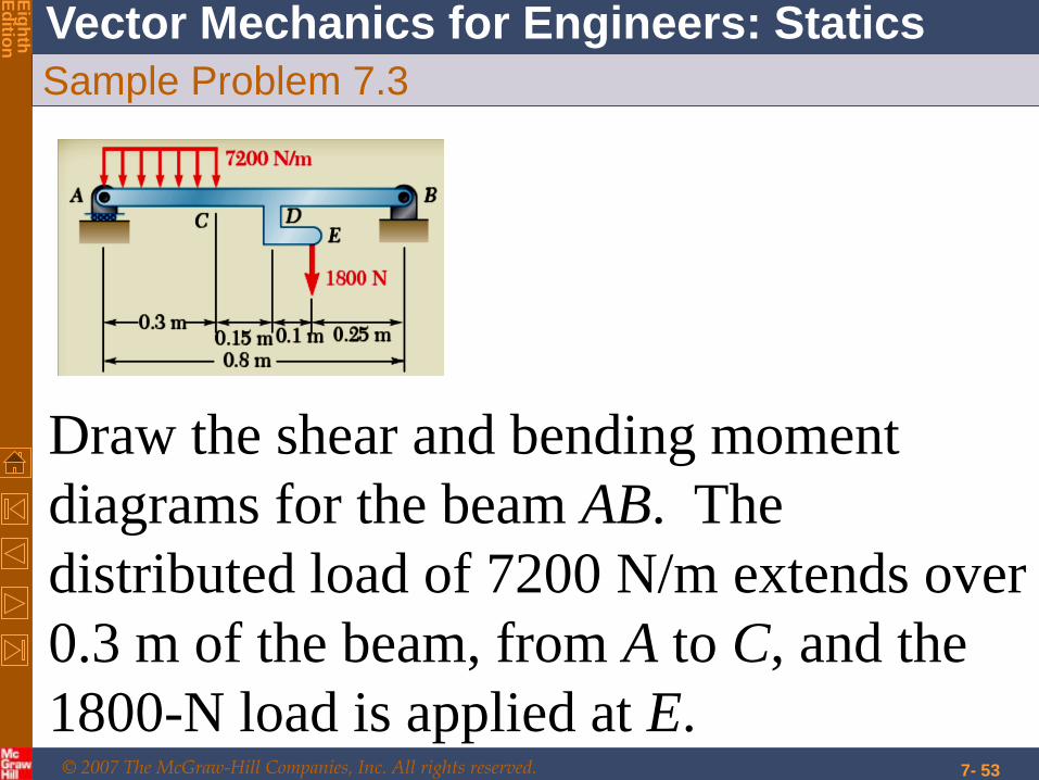
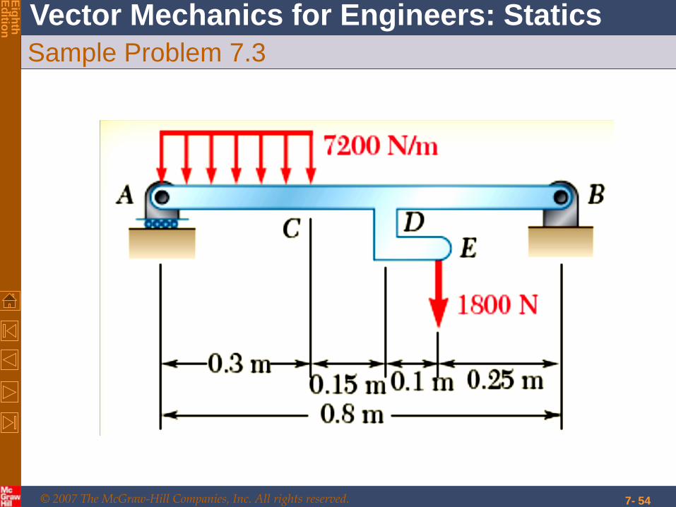
Sample Problem 7.3
7- 53
Draw the shear and bending moment
diagrams for the beam AB. The
distributed load of 7200 N/m extends over
0.3 m of the beam, from A to C, and the
1800-N load is applied at E.
© 2007 The McGraw-Hill Companies, Inc. All rights reserved.
Vector Mechanics for Engineers: Statics
Eig
hth
E
ditio
n
Sample Problem 7.3
7- 54
© 2007 The McGraw-Hill Companies, Inc. All rights reserved.
Vector Mechanics for Engineers: Statics
Eig
hth
E
ditio
n
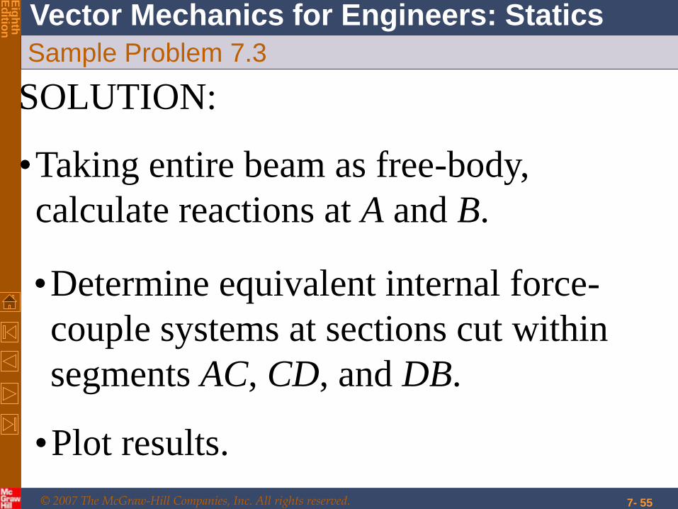
Sample Problem 7.3
7- 55
SOLUTION:
•Taking entire beam as free-body,
calculate reactions at A and B.
•Determine equivalent internal force-
couple systems at sections cut within
segments AC, CD, and DB.
•Plot results.

© 2007 The McGraw-Hill Companies, Inc. All rights reserved.
Vector Mechanics for Engineers: Statics
Eig
hth
E
ditio
n
Sample Problem 7.3
7- 56
SOLUTION:
• Taking entire beam as a free-body, calculate
reactions at A and B.
:0AM
0m550N1800m150N2160m80 ...By
N51642 .By
:0BM
0m8.0N25.0N1800m65.0N2160 A
N52317.A
:0xF 0xB
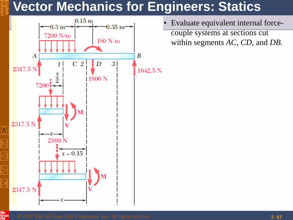
• Note: The 1800-N load at E may be replaced by
a 1800-N force and 180-N . m couple at D.
© 2007 The McGraw-Hill Companies, Inc. All rights reserved.
Vector Mechanics for Engineers: Statics
Eig
hth
E
ditio
n
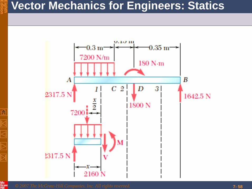
Sample Problem 7.3
7- 57
• Evaluate equivalent internal force-
couple systems at sections cut
within segments AC, CD, and DB.
© 2007 The McGraw-Hill Companies, Inc. All rights reserved.
Vector Mechanics for Engineers: Statics
Eig
hth
E
ditio
n
7- 58
© 2007 The McGraw-Hill Companies, Inc. All rights reserved.
Vector Mechanics for Engineers: Statics
Eig
hth
E
ditio
n
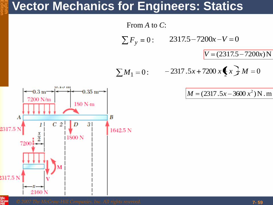
7- 59
:01M 072005231721 Mxxx.
m.N )360052317( 2xx.M
From A to C:
:0yF 0720052317 Vx.
N)720052317( x.V
© 2007 The McGraw-Hill Companies, Inc. All rights reserved.
Vector Mechanics for Engineers: Statics
Eig
hth
E
ditio
n
7- 60
© 2007 The McGraw-Hill Companies, Inc. All rights reserved.
Vector Mechanics for Engineers: Statics
Eig
hth
E
ditio
n
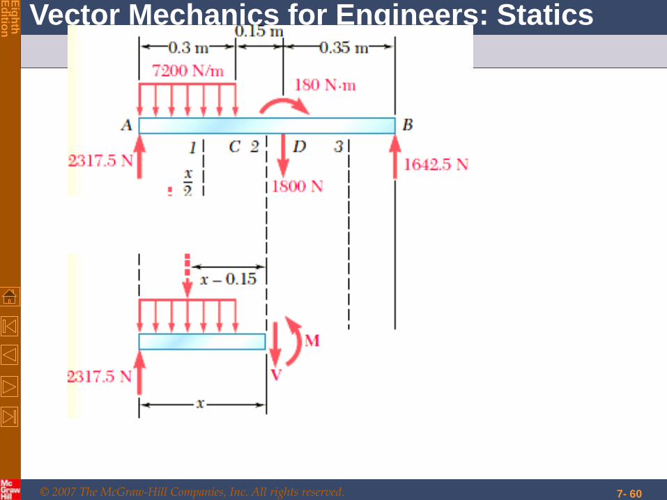
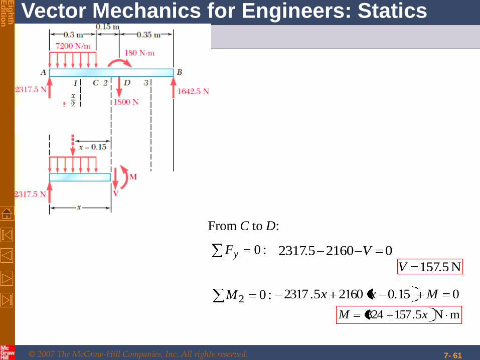
Sample Problem 7.3
7- 61
:02M 0150216052317 M.xx.
mN 5157324 x.M
From C to D:
:0yF 0216052317 V.
N 5157.V
© 2007 The McGraw-Hill Companies, Inc. All rights reserved.
Vector Mechanics for Engineers: Statics
Eig
hth
E
ditio
n
7- 62
© 2007 The McGraw-Hill Companies, Inc. All rights reserved.
Vector Mechanics for Engineers: Statics
Eig
hth
E
ditio
n
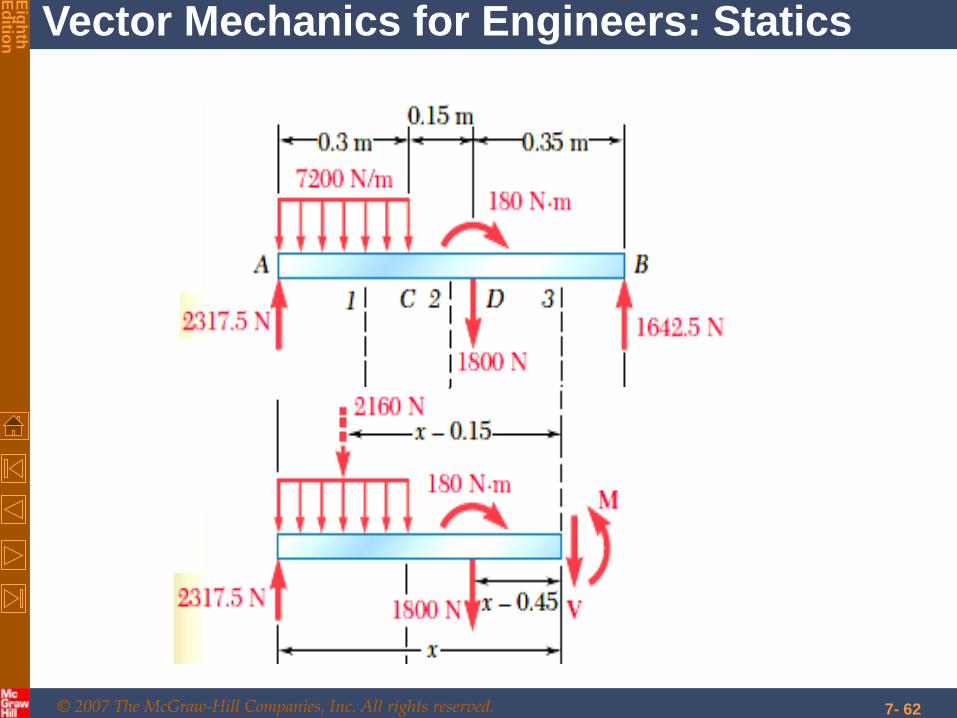
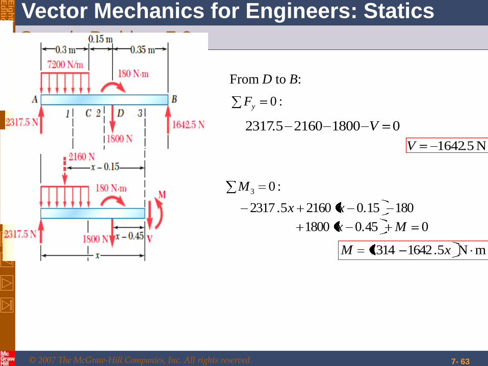
Sample Problem 7.3
7- 63
:03M
04501800
180150216052317
M.x
.xx.
mN 516421314 x.M
From D to B:
:0yF
01800216052317 V.
N 51642.V
© 2007 The McGraw-Hill Companies, Inc. All rights reserved.
Vector Mechanics for Engineers: Statics
Eig
hth
E
ditio
n
Sample Problem 7.3
7- 64
© 2007 The McGraw-Hill Companies, Inc. All rights reserved.
Vector Mechanics for Engineers: Statics
Eig
hth
E
ditio
n
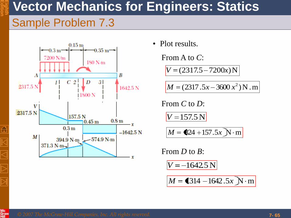
Sample Problem 7.3
7- 65
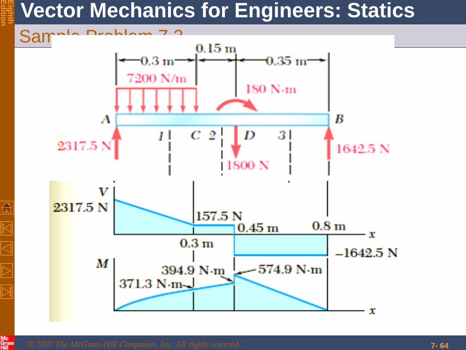
• Plot results.
From A to C:
From C to D:
From D to B:
N)720052317( x.V
m.N )360052317( 2xx.M
N 5157.V
mN 5157324 x.M
N 51642.V
mN 516421314 x.M
© 2007 The McGraw-Hill Companies, Inc. All rights reserved.
Vector Mechanics for Engineers: Statics
Eig
hth
E
ditio
n
7- 66
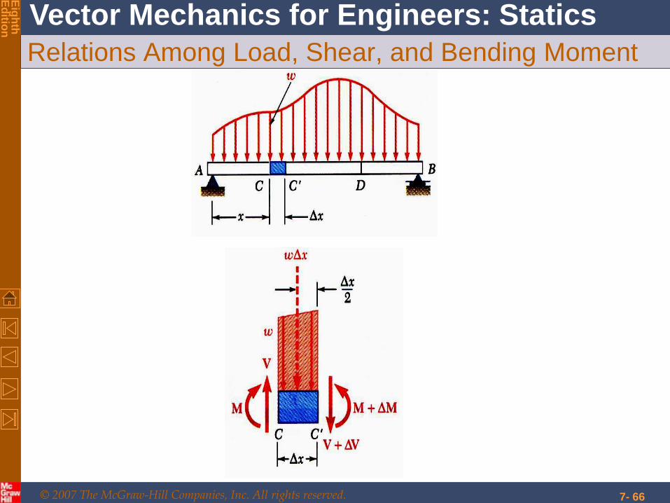
Relations Among Load, Shear, and Bending Moment
© 2007 The McGraw-Hill Companies, Inc. All rights reserved.
Vector Mechanics for Engineers: Statics
Eig
hth
E
ditio
n
7- 67
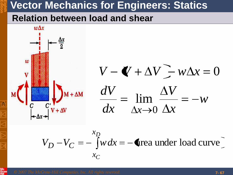
Relation between load and shear
wx
V
dx
dV
xwVVV
x 0lim
0
curve loadunder areaD
C
x
xCD dxwVV
© 2007 The McGraw-Hill Companies, Inc. All rights reserved.
Vector Mechanics for Engineers: Statics
Eig
hth
E
ditio
n
7- 68
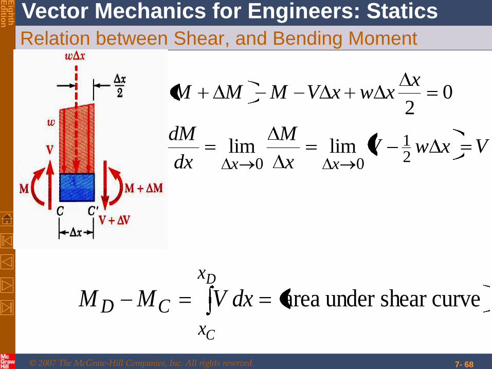
Relation between Shear, and Bending Moment
VxwVx
M
dx
dM
xxwxVMMM
xx 21
00limlim
02
curveshear under areaD
C
x
xCD dxVMM
© 2007 The McGraw-Hill Companies, Inc. All rights reserved.
Vector Mechanics for Engineers: Statics
Eig
hth
E
ditio
n
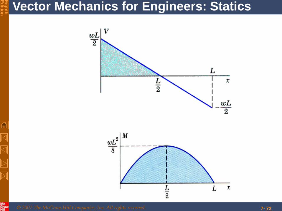
7- 69
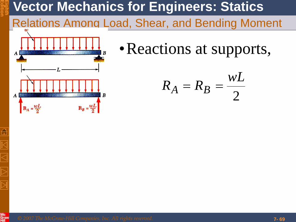
Relations Among Load, Shear, and Bending Moment
•Reactions at supports,
2
wLRR BA
© 2007 The McGraw-Hill Companies, Inc. All rights reserved.
Vector Mechanics for Engineers: Statics
Eig
hth
E
ditio
n
7- 70
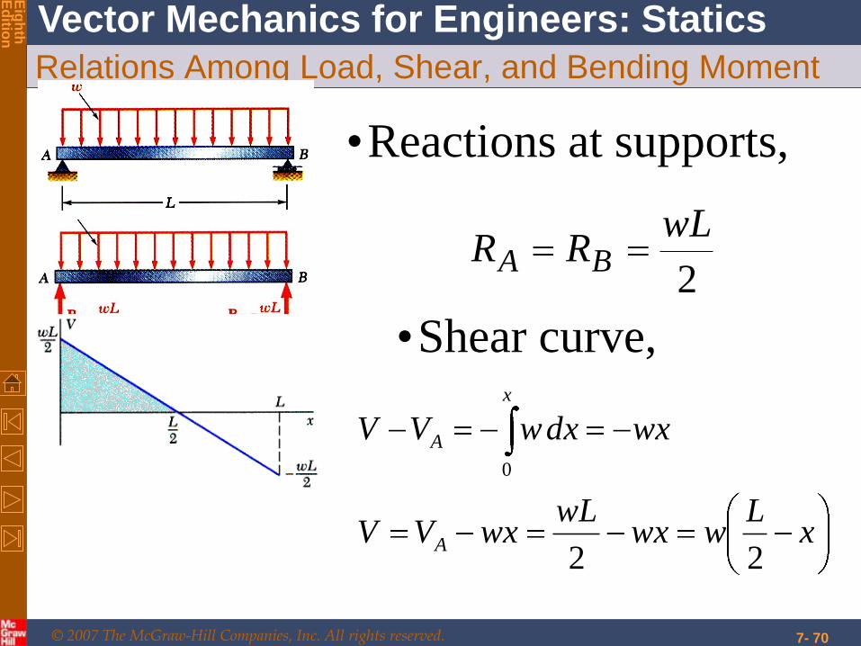
Relations Among Load, Shear, and Bending Moment
•Reactions at supports,
2
wLRR BA
•Shear curve,
xL
wwxwL
wxVV
wxdxwVV
A
x
A
22
0

© 2007 The McGraw-Hill Companies, Inc. All rights reserved.
Vector Mechanics for Engineers: Statics
Eig
hth
E
ditio
n
7- 71
•Moment curve,
0at 8
22
2
max
2
0
0
Vdx
dMM
wLM
xxLw
dxxL
wM
VdxMM
x
x
A
© 2007 The McGraw-Hill Companies, Inc. All rights reserved.
Vector Mechanics for Engineers: Statics
Eig
hth
E
ditio
n
7- 72
© 2007 The McGraw-Hill Companies, Inc. All rights reserved.
Vector Mechanics for Engineers: Statics
Eig
hth
E
ditio
n
7- 73
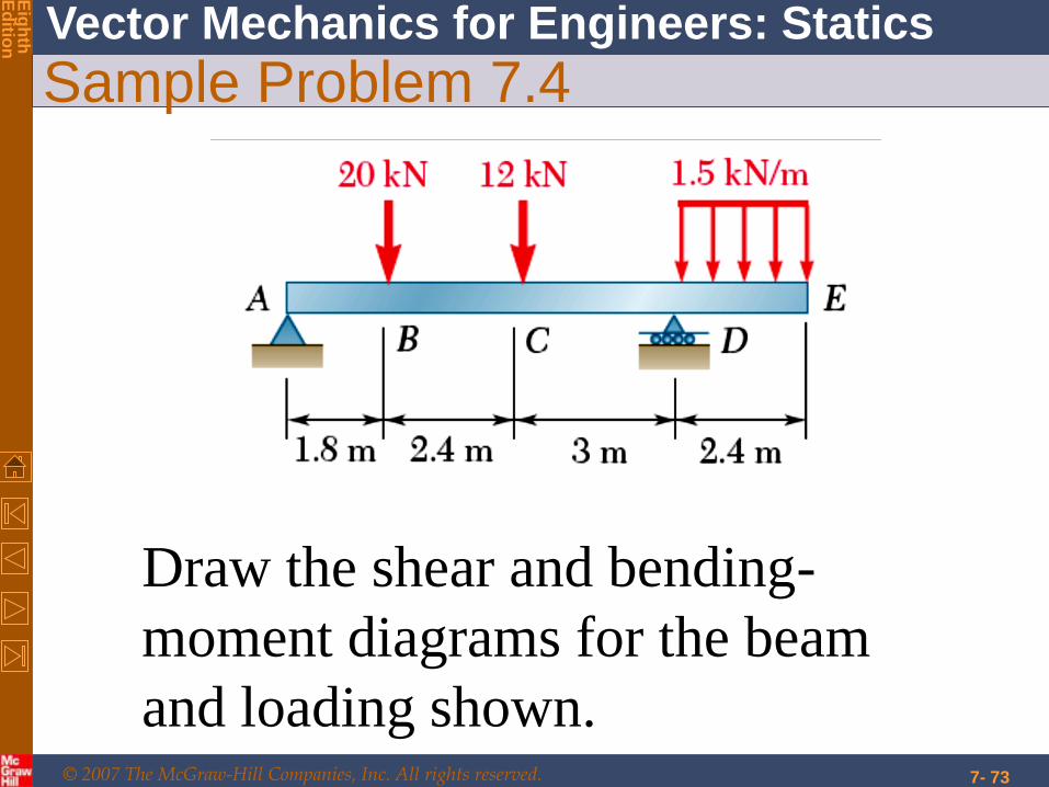
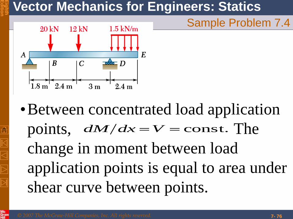
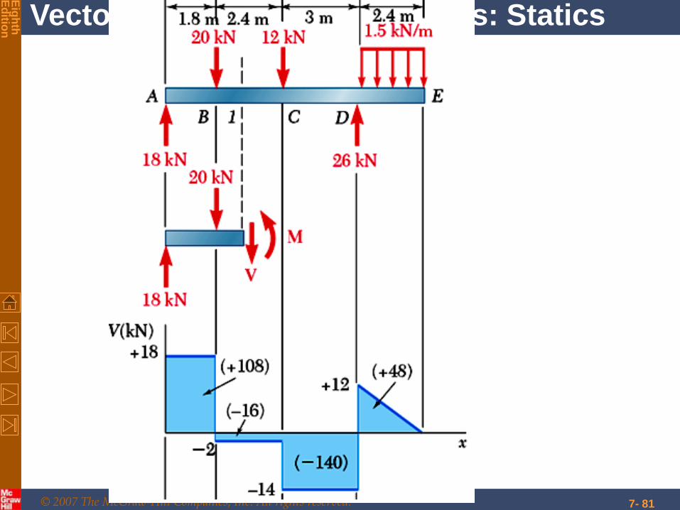
Sample Problem 7.4
Draw the shear and bending-
moment diagrams for the beam
and loading shown.
© 2007 The McGraw-Hill Companies, Inc. All rights reserved.
Vector Mechanics for Engineers: Statics
Eig
hth
E
ditio
n
7- 74
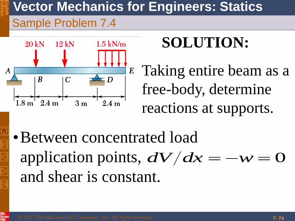
Sample Problem 7.4
SOLUTION:
•Taking entire beam as a
free-body, determine
reactions at supports.
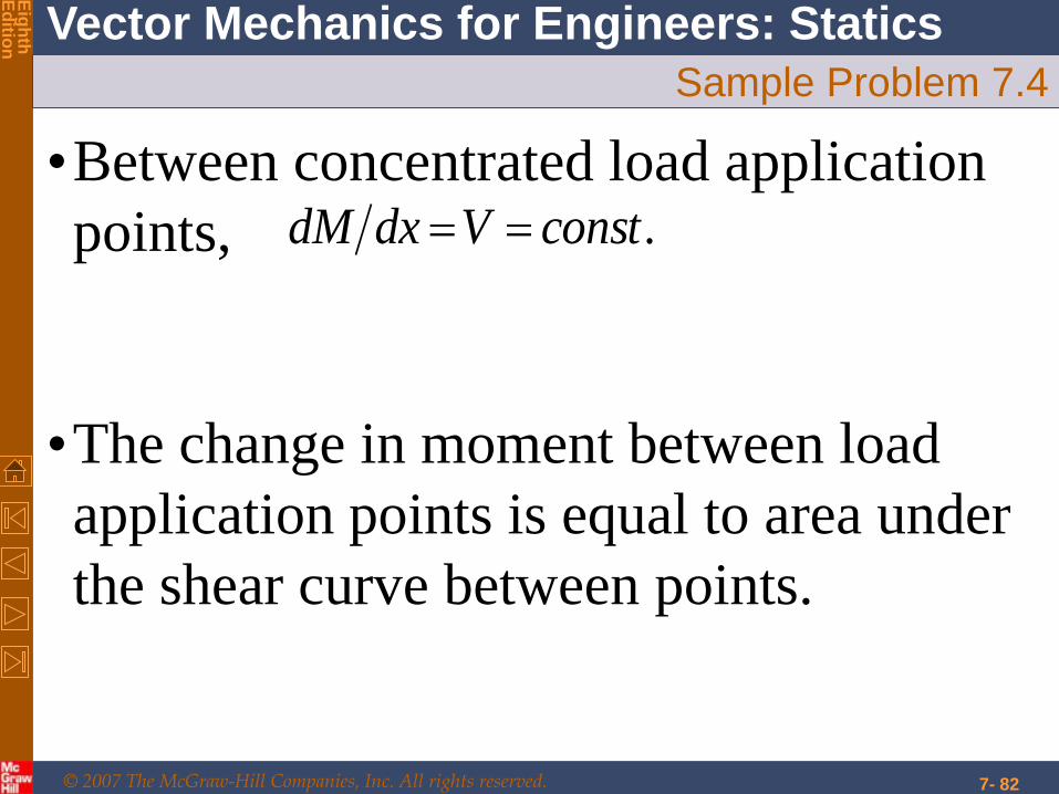
•Between concentrated load
application points,
and shear is constant.
0wdxdV
© 2007 The McGraw-Hill Companies, Inc. All rights reserved.
Vector Mechanics for Engineers: Statics
Eig
hth
E
ditio
n
7- 75
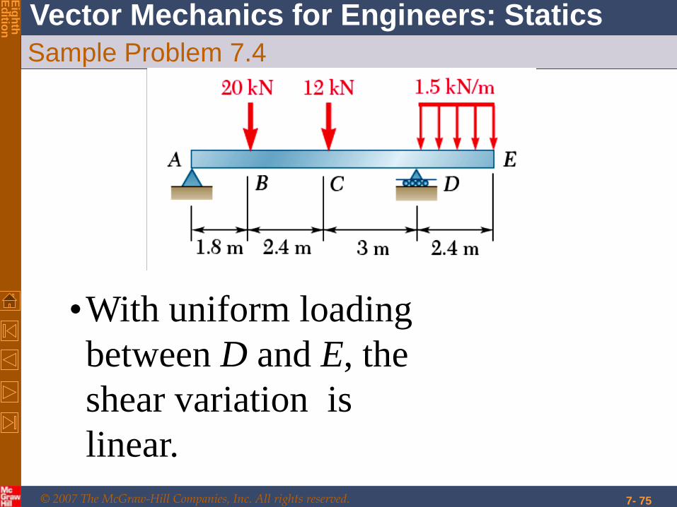
Sample Problem 7.4
•With uniform loading
between D and E, the
shear variation is
linear.
© 2007 The McGraw-Hill Companies, Inc. All rights reserved.
Vector Mechanics for Engineers: Statics
Eig
hth
E
ditio
n
7- 76
Sample Problem 7.4
•Between concentrated load application
points, The
change in moment between load
application points is equal to area under
shear curve between points.
const.VdxdM
© 2007 The McGraw-Hill Companies, Inc. All rights reserved.
Vector Mechanics for Engineers: Statics
Eig
hth
E
ditio
n
7- 77
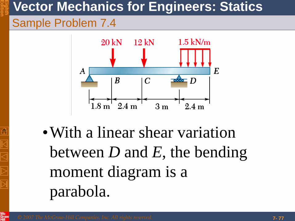
Sample Problem 7.4
•With a linear shear variation
between D and E, the bending
moment diagram is a
parabola.
© 2007 The McGraw-Hill Companies, Inc. All rights reserved.
Vector Mechanics for Engineers: Statics
Eig
hth
E
ditio
n
7- 78
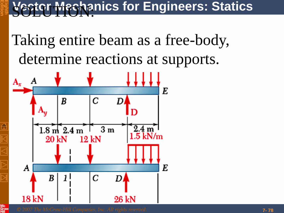
SOLUTION:
Taking entire beam as a free-body,
determine reactions at supports.
© 2007 The McGraw-Hill Companies, Inc. All rights reserved.
Vector Mechanics for Engineers: Statics
Eig
hth
E
ditio
n
7- 79
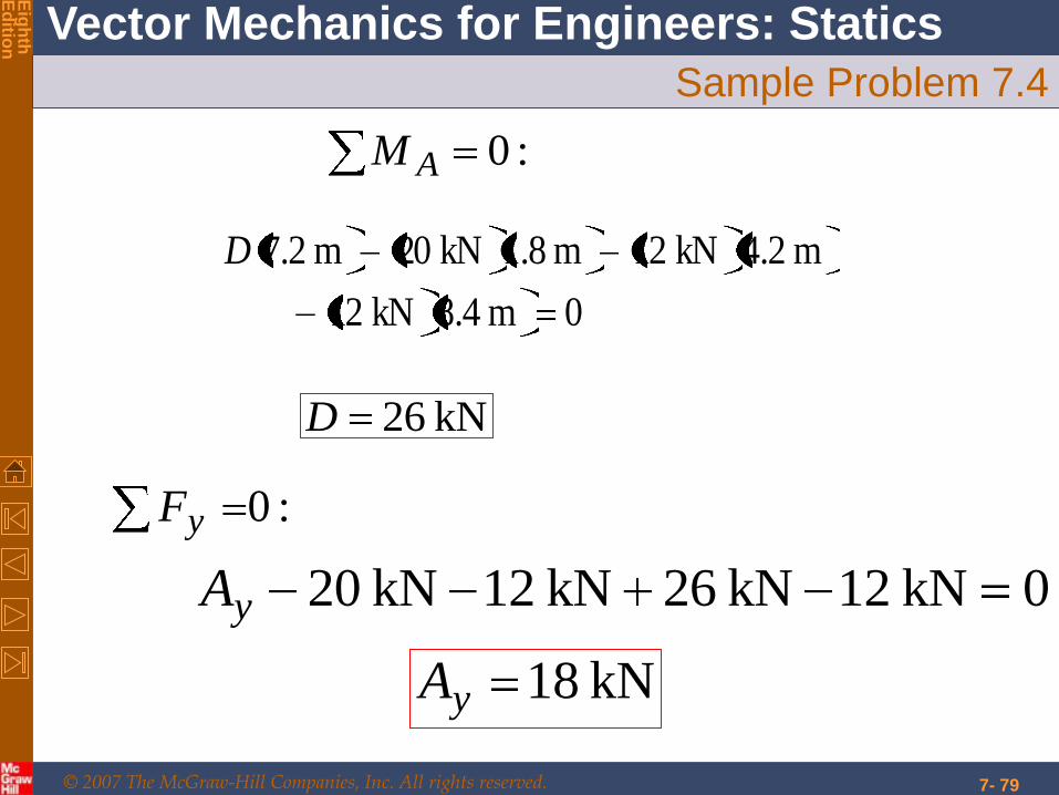
Sample Problem 7.4
:0AM
0m .48kN 12
m .24kN 12m .81kN 20m .27D
kN 26D
:0yF
0kN 12kN 26kN 12kN 20yA
kN 18yA

© 2007 The McGraw-Hill Companies, Inc. All rights reserved.
Vector Mechanics for Engineers: Statics
Eig
hth
E
ditio
n
7- 80
Sample Problem 7.4
•Between concentrated
load application points,
and shear is constant.
0wdxdV
•With uniform loading
between D and E, the
shear variation is linear.
© 2007 The McGraw-Hill Companies, Inc. All rights reserved.
Vector Mechanics for Engineers: Statics
Eig
hth
E
ditio
n
7- 81
© 2007 The McGraw-Hill Companies, Inc. All rights reserved.
Vector Mechanics for Engineers: Statics
Eig
hth
E
ditio
n
7- 82
Sample Problem 7.4
•Between concentrated load application
points,
•The change in moment between load
application points is equal to area under
the shear curve between points.
.constVdxdM
© 2007 The McGraw-Hill Companies, Inc. All rights reserved.
Vector Mechanics for Engineers: Statics
Eig
hth
E
ditio
n
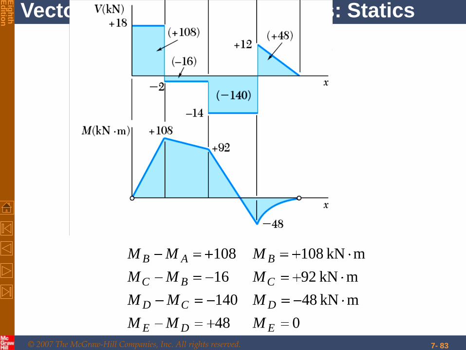
7- 83
048
mkN 48140
mkN 9216
mkN 108108
EDE
DCD
CBC
BAB
MMM
MMM
MMM
MMM
© 2007 The McGraw-Hill Companies, Inc. All rights reserved.
Vector Mechanics for Engineers: Statics
Eig
hth
E
ditio
n
7- 84
Sample Problem 7.4
•With a linear shear variation between D
and E, the bending moment diagram is a
parabola.

© 2007 The McGraw-Hill Companies, Inc. All rights reserved.
Vector Mechanics for Engineers: Statics
Eig
hth
E
ditio
n
7- 85
Sample Problem 7.4
•With a linear shear variation between
D and E, the bending moment diagram
is a parabola.
© 2007 The McGraw-Hill Companies, Inc. All rights reserved.
Vector Mechanics for Engineers: Statics
Eig
hth
E
ditio
n
7- 86
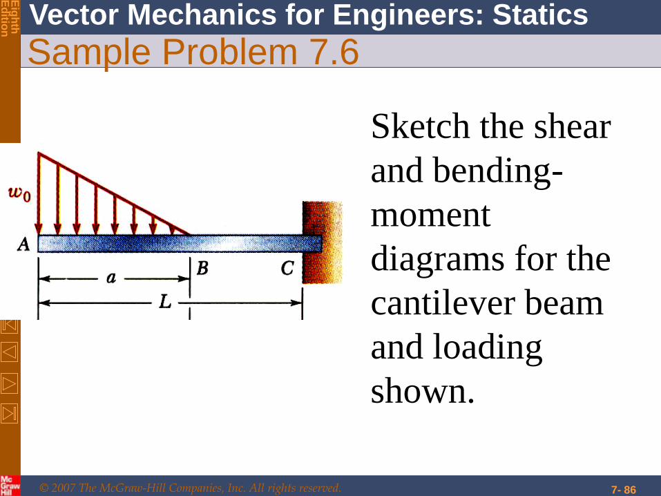
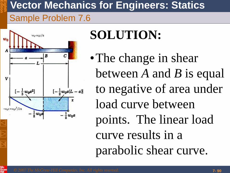
Sample Problem 7.6
Sketch the shear
and bending-
moment
diagrams for the
cantilever beam
and loading
shown.
© 2007 The McGraw-Hill Companies, Inc. All rights reserved.
Vector Mechanics for Engineers: Statics
Eig
hth
E
ditio
n
7- 87
Sample Problem 7.6
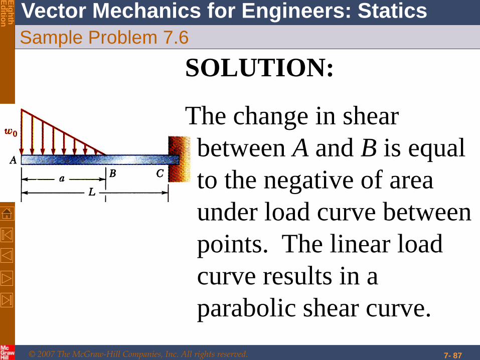
SOLUTION:
The change in shear
between A and B is equal
to the negative of area
under load curve between
points. The linear load
curve results in a
parabolic shear curve.
© 2007 The McGraw-Hill Companies, Inc. All rights reserved.
Vector Mechanics for Engineers: Statics
Eig
hth
E
ditio
n
7- 88
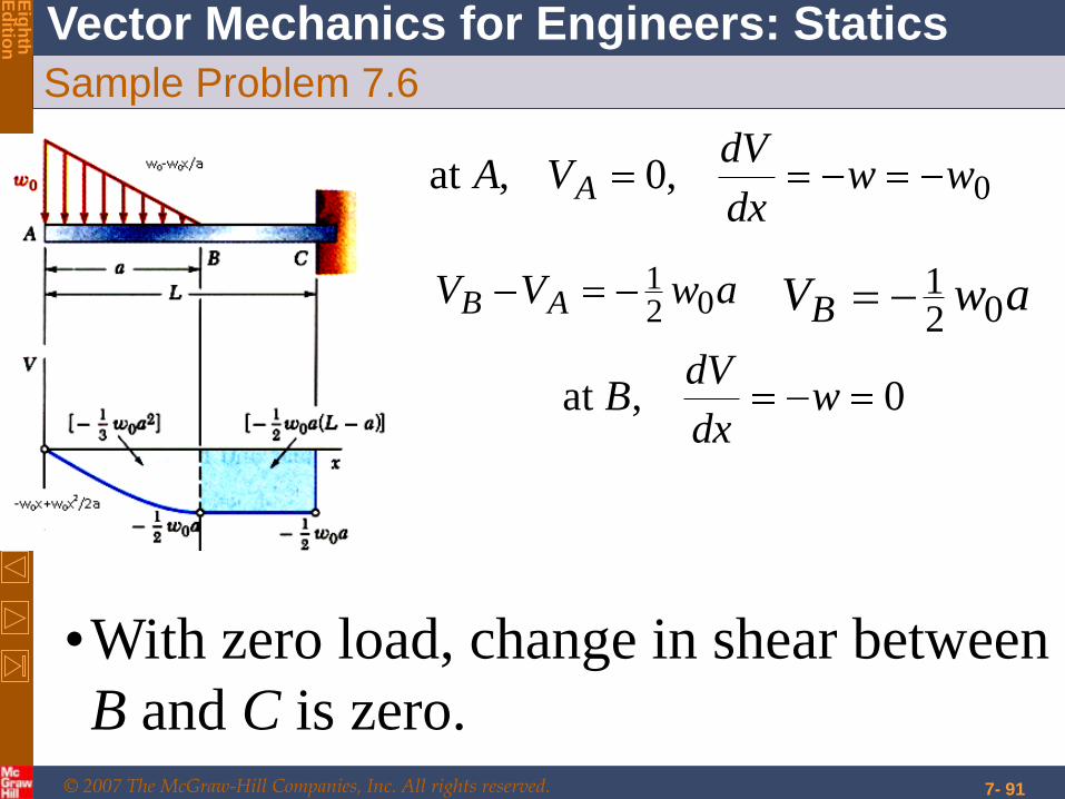
Sample Problem 7.6
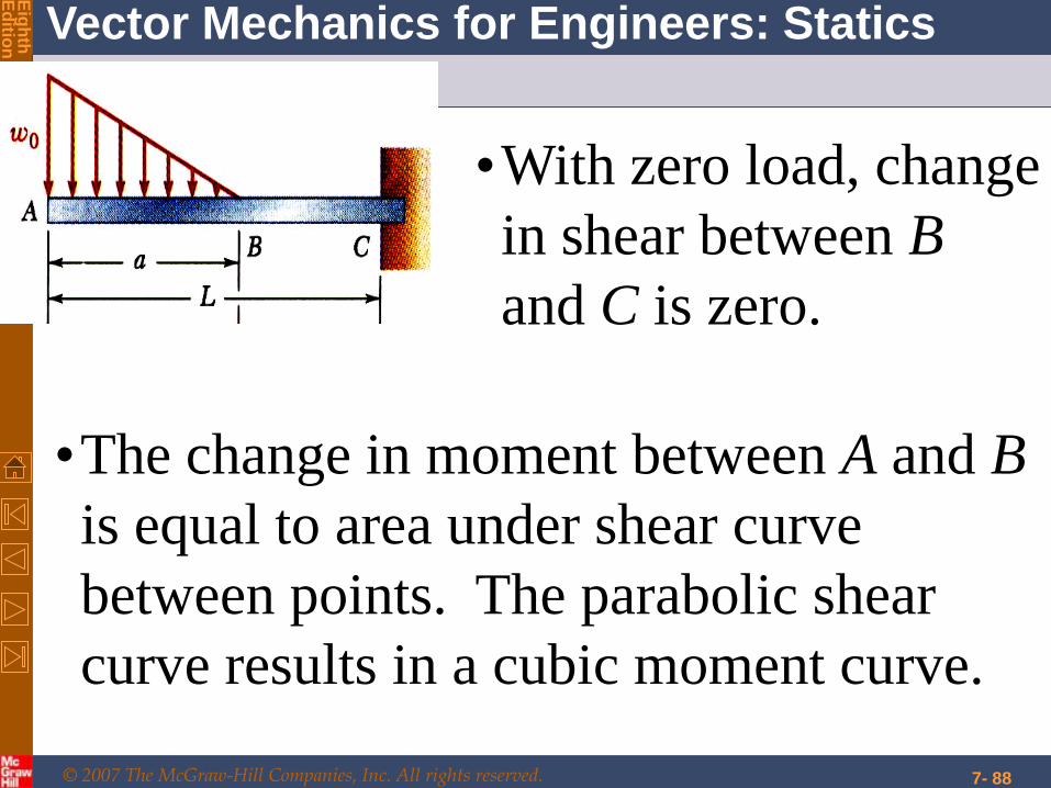
•With zero load, change
in shear between B
and C is zero.
•The change in moment between A and B
is equal to area under shear curve
between points. The parabolic shear
curve results in a cubic moment curve.
© 2007 The McGraw-Hill Companies, Inc. All rights reserved.
Vector Mechanics for Engineers: Statics
Eig
hth
E
ditio
n
7- 89
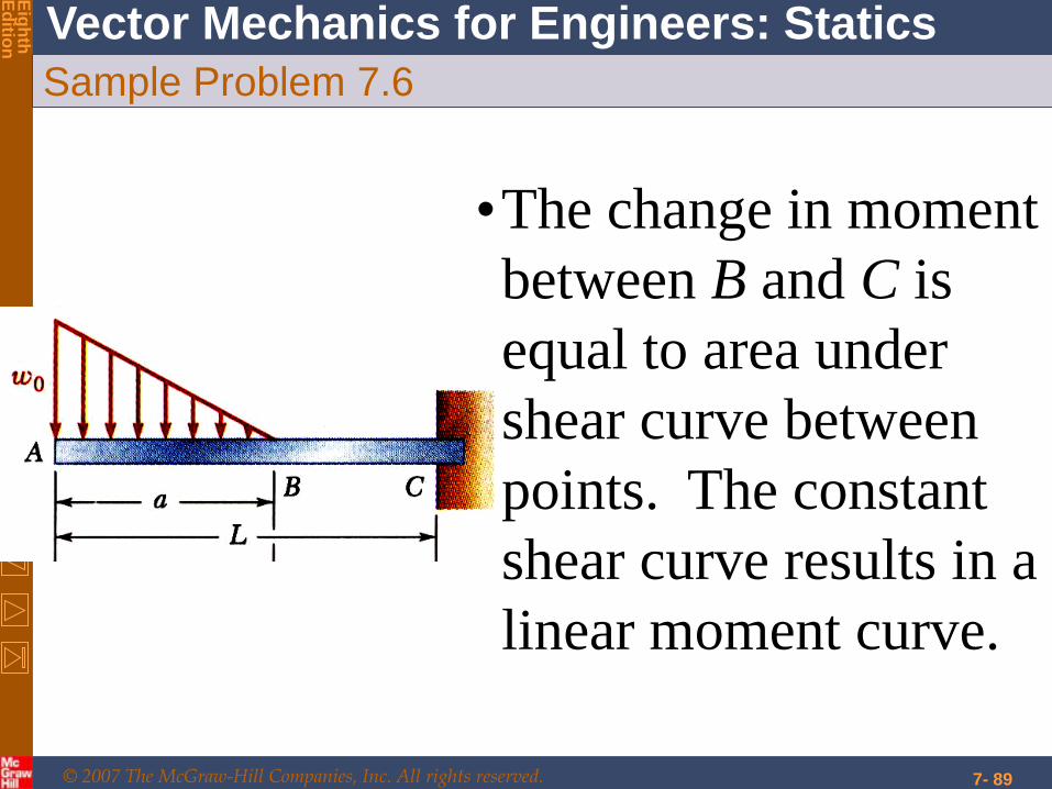
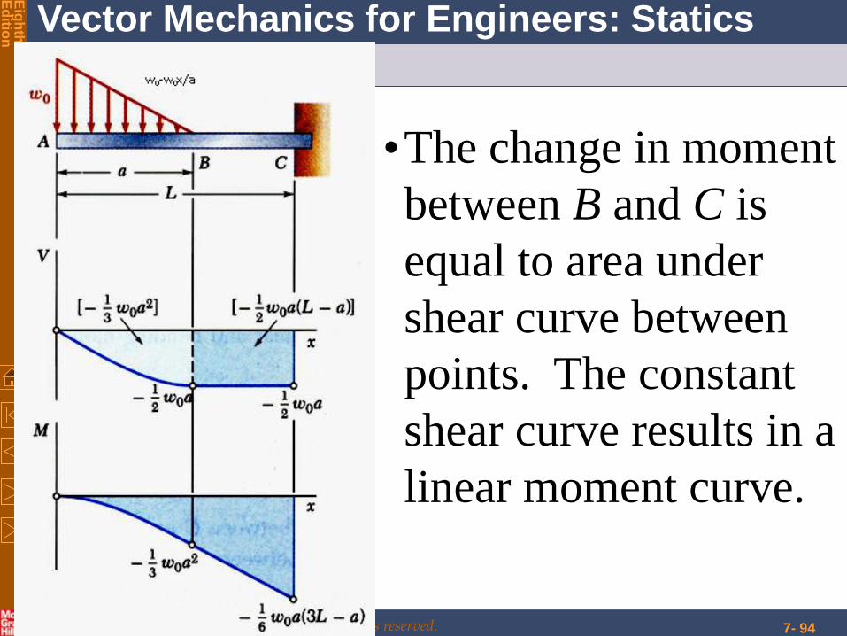
Sample Problem 7.6
•The change in moment
between B and C is
equal to area under
shear curve between
points. The constant
shear curve results in a
linear moment curve.
© 2007 The McGraw-Hill Companies, Inc. All rights reserved.
Vector Mechanics for Engineers: Statics
Eig
hth
E
ditio
n
7- 90
Sample Problem 7.6
SOLUTION:
•The change in shear
between A and B is equal
to negative of area under
load curve between
points. The linear load
curve results in a
parabolic shear curve.
© 2007 The McGraw-Hill Companies, Inc. All rights reserved.
Vector Mechanics for Engineers: Statics
Eig
hth
E
ditio
n
7- 91
Sample Problem 7.6
•With zero load, change in shear between
B and C is zero.
awVV AB 021 awVB 02
1
0,at wdx
dVB
0,0,at wwdx
dVVA A

© 2007 The McGraw-Hill Companies, Inc. All rights reserved.
Vector Mechanics for Engineers: Statics
Eig
hth
E
ditio
n
7- 92
Sample Problem 7.6
•The change in moment
between A and B is
equal to area under
shear curve between
the points. The
parabolic shear curve
results in a cubic
moment curve.

© 2007 The McGraw-Hill Companies, Inc. All rights reserved.
Vector Mechanics for Engineers: Statics
Eig
hth
E
ditio
n
7- 93
Sample Problem 7.6
aLawMaLawMM
awMawMM
CBC
BAB
3061
021
203
1203
1
0,0,at Vdx
dMMA A
© 2007 The McGraw-Hill Companies, Inc. All rights reserved.
Vector Mechanics for Engineers: Statics
Eig
hth
E
ditio
n
7- 94
Sample Problem 7.6
•The change in moment
between B and C is
equal to area under
shear curve between
points. The constant
shear curve results in a
linear moment curve.