eip-3500 owners manual
TRANSCRIPT

EIP-3500
OWNER'S MANUAL
EIKI INDUSTRIAL CO., LTD.

IMPORTANTFor your assistance in reporting the loss or theft of yourProjector, please record the Serial Number located onthe bottom of the projector and retain this information.Before recycling the packaging, please ensure that youhave checked the contents of the carton thoroughlyagainst the list of “Supplied accessories” on page 10.
Model No.: EIP-3500
Serial No.:

SPECIAL NOTE FOR USERS IN THE U.K.The mains lead of this product is fitted with a non-rewireable (moulded) plug incorporating a 10A fuse. Shouldthe fuse need to be replaced, a BSI or ASTA approved BS 1362 fuse marked or and of the same rating asabove, which is also indicated on the pin face of the plug, must be used.Always refit the fuse cover after replacing the fuse. Never use the plug without the fuse cover fitted.In the unlikely event of the socket outlet in your home not being compatible with the plug supplied, cut off themains plug and fit an appropriate type.
DANGER:The fuse from the cut-off plug should be removed and the cut-off plug destroyed immediately and disposed ofin a safe manner.Under no circumstances should the cut-off plug be inserted elsewhere into a 10A socket outlet, as a seriouselectric shock may occur.To fit an appropriate plug to the mains lead, follow the instructions below:
WARNING:THIS APPARATUS MUST BE EARTHED.IMPORTANT:The wires in this mains lead are coloured in accordance with the following code:
Green-and-yellow : EarthBlue : NeutralBrown : Live
As the colours of the wires in the mains lead of this apparatus may not correspond with the coloured markingsidentifying the terminals in your plug proceed as follows:• The wire which is coloured green-and-yellow must be connected to the terminal in the plug which is marked by
the letter E or by the safety earth symbol or coloured green or green-and-yellow.• The wire which is coloured blue must be connected to the terminal which is marked with the letter N or coloured
black.• The wire which is coloured brown must be connected to the terminal which is marked with the letter L or coloured
red.
IF YOU HAVE ANY DOUBT, CONSULT A QUALIFIED ELECTRICIAN.

The supplied CD-ROM contains SETUP GUIDE in English, German, French, Spanish, Italian, Portuguese andJapanese.
Die mitgelieferte CD-ROM enthält Einrichtungs-Anleitung in Englisch, Deutsch, Französisch, Spanisch, Italienisch,Portugiesisch und Japanisch.
Le CD-ROM fourni contient le guide d’installation en anglais, allemand, français, espagnol, italien, portugais etjaponais.
Den medföljande CD-ROM-skivan innehåller uppställningsguide på engelska, tyska, franska, spanska,italienska, portugisiska och japanska.
El CD-ROM suministrado contiene guía de configuración en inglés, alemán, francés, español, italiano,portugués y japonés.
Il CD-ROM in dotazione contiene guia di impostazione in inglese, tedesco, francese, spagnolo, italiano,portoghese e giapponese.
De meegeleverde CD-ROM bevat instelgids in het Engels, Duits, Frans, Spaans, Italiaans, Portugees enJapans.
O CD-ROM fornecido contém guia de configuração em Inglês, Alemão, Francês, Espanhol, Italiano, Portuguêse Japonês.

1
Before using the projector, please read this operation manual carefully.
1. WARRANTYThis is to assure that you immediately receive the full benefit of the parts, service and laborwarranty applicable to your purchase.
2. CONSUMER PRODUCT SAFETY ACTTo ensure that you will promptly receive any safety notification of inspection, modification, orrecall that EIKI may be required to give under the 1972 Consumer Product Safety Act, PLEASEREAD CAREFULLY THE IMPORTANT “LIMITED WARRANTY” CLAUSE.
WARNING: High brightness light source. Do not stare into the beam of light, or view directly. Be especiallycareful that children do not stare directly into the beam of light.
WARNING: To reduce the risk of fire or electric shock, do not expose this product torain or moisture.
WARNING: FCC Regulations state that any unauthorized changes or modifications to this equipment notexpressly approved by the manufacturer could void the user’s authority to operate this equip-ment.
CAUTION: TO REDUCE THE RISK OF ELECTRIC SHOCK,DO NOT REMOVE COVER.
NO USER-SERVICEABLE PARTS EXCEPT LAMP UNIT.REFER SERVICING TO QUALIFIED SERVICE
PERSONNEL.
The lightning flash with arrowhead symbol,within an equilateral triangle, is intended toalert the user to the presence of uninsulated“dangerous voltage” within the product’senclosure that may be of sufficient magnitudeto constitute a risk or electric shock topersons.
The exclamation point within a triangle isintended to alert the user to the presence ofimportant operating and maintenance(servicing) instructions in the literatureaccompanying the product.
Introduction ENGLISH
CAUTIONRISK OF ELECTRIC SHOCK.DO NOT REMOVE SCREWSEXCEPT SPECIFIED USER
SERVICE SCREW.
INFORMATIONThis equipment has been tested and found to comply with the limits for a Class A digital device,pursuant to Part 15 of the FCC Rules. These limits are designed to provide reasonable protectionagainst harmful interference when the equipment is operated in a commercial environment. Thisequipment generates, uses, and can radiate radio frequency energy and, if not installed and used inaccordance with the operation manual, may cause harmful interference to radio communications.Operation of this equipment in a residential area is likely to cause harmful interference, in which casethe user will be required to correct the interference at his own expense.
See bottom of projector.
The enclosed computer cable must be used with the device. The cable is provided to ensure that the devicecomplies with FCC Class A verification.
U.S.A. ONLY
U.S.A. ONLY
U.S.A. ONLY
U.S.A. ONLY
WARNING:This is a Class A product. In a domestic environment this product may cause radio interference inwhich case the user may be required to take adequate measures.

2
WARNING:The cooling fan in this projector continues to run for about 90 seconds after the projector enters the standby mode.During normal operation, when putting the projector into standby mode always use the POWER button on theprojector or on the remote control. Ensure the cooling fan has stopped before disconnecting the power cord.DURING NORMAL OPERATION, NEVER TURN THE PROJECTOR OFF BY DISCONNECTING THE POWER CORD.FAILURE TO OBSERVE THIS WILL RESULT IN PREMATURE LAMP FAILURE.
Caution Concerning Lamp ReplacementSee “Replacing the Lamp” on page 66.
PRODUCT DISPOSALThis projector utilizes tin-lead solder, and a pressurized lamp containing a small amount of mercury. Disposal ofthese materials may be regulated due to environmental considerations. For disposal or recycling information,please contact your local authorities or, if you are located in the United States of America, the Electronic IndustriesAlliance: www.eiae.org .
LAMP REPLACEMENT WARNING :TURN OFF THE LAMP AND DISCONNECT POWER CORD BEFORE OPENING THIS COVER. HOT SURFACE INSIDE. ALLOW 1 HOUR TO COOL BEFORE REPLACING THE LAMP. REPLACE WITH SAME EIKI LAMP UNIT MODEL AH-35001 ONLY.HIGH PRESSURE LAMP : RISK OF EXPLOSION. POTENTIAL HAZARD OF GLASS PARTICLES IF LAMP HAS RUPTURED. HANDLE WITH CARE. SEE OPERATION MANUAL.SERVICEMAN-WARNING : USE RADIATION EYE AND SKIN PROTECTION DURING SERVICING.
AVERTISSEMENT CONCERNANT LE REMPLACEMENT DE LA LAMPE :
ETEINDRE LA LAMPE ET DEBRANCHER LE CORDON D’ALIMENTATION AVANT D’OUVRIR LE COUVERCLE. L’INTERIEUR DU BOITIER ETANT EXTREMEMENT CHAUD, ATTENDRE 1 HEURE AVANT DE PROCEDER AU REMPLACEMENT DE LA LAMPE. NE REMPLACER QUE PAR UNE LAMPE EIKI DE MODÈLE AH-35001.LAMPE A HAUTE PRESSION : RISQUE D’EXPLOSION. DANGER POTENTIEL DE PARTICULES DE VERRE EN CAS D’ECLATEMENT DE LA LAMPE. A MANIPULER AVEC PRECAUTION.SE REPORTER AU MODE D’EMPLOI.AVERTISSEMENT – REPARATEUR : SE PROTEGER LES YEUX ET LA PEAU DES RADIATIONS LORS DES REPARATIONS.
This EIKI projector uses a DMD panel. This very sophisticated panel contains 786,432 pixels micromirrors. As withany high technology electronic equipment such as large screen TVs, video systems and video cameras, there arecertain acceptable tolerances that the equipment must conform to.This unit has some inactive pixels within acceptable tolerances which may result in inactive dots on the picturescreen. This will not affect the picture quality or the life expectancy of the unit.
• DLPTM (Digital Light Processing) and DMDTM (Digital Micromirror Device) are trademarks of Texas Instru-ments, Inc.
• Microsoft® and Windows® are registered trademarks of Microsoft Corporation in the United States and/orother countries.
• PC/AT is a registered trademark of International Business Machines Corporation in the United States.• Adobe® Reader® is a trademark of Adobe Systems Incorporated.• Macintosh® is a registered trademark of Apple Computer, Inc. in the United States and/or other countries.• All other company or product names are trademarks or registered trademarks of their respective compa-
nies.• Some IC chips in this product include confidential and/or trade secret property belonging to Texas Instru-
ments. Therefore you may not copy, modify, adapt, translate, distribute, reverse engineer, reverse as-semble or discompile the contents thereof.

3
40
The menu can be operated to achieve two functions, adjustments and settings. (For settingthe menu items, see pages 42 and 43. )
Using the Menu Screen
Menu Selections (Adjustments)Example: Adjusting “Bright”•This operation can also be performed by using the buttons on the projector.
Menu icons
ENTER button
MENU button
UNDO button
MOUSE/ Adjustmentbutton ('/"/\/|)
Adjustment buttons ('/"/\/|)
MENU button
ENTER button
Example: “Picture” screen menu forINPUT 1 (RGB) mode
1 Press .•The “Picture” menu screen for the se-
lected input mode is displayed.
2 Press ||||| or \\\\\ to display the othermenu screens.•The menu icon for the selected menu
screen is highlighted.
Note
•The “Fine Sync” menu is not availablefor selecting INPUT 3 or INPUT 4.
Menu icon Menu screen
Picture
Fine Sync
Options1
Options2
Language
How to Read this Operation Manual
••••• In this operation manual, the illustrations and on-screen displays are simplified for explana-tion. This may differ from the actual on-screen display.
Info ...........Indicates safeguards when using the projector.
For Future Reference
Maintenance Troubleshooting Index
Page 74Pages 70 and 71Page 63
On-screen display
Button used inthis step
Note ........Indicates additional information for setting up and operating the projector.
Buttons used in thisoperation Buttons used in this
operation

4
Contents
PreparingSetting up the Projector .............................. 19
Setting up the Projector ..................................... 19Projecting a Reversed Image ............................ 20
ConnectionsConnections ................................................. 21
INPUT/OUTPUT Terminals and ConnectableMain Equipment .......................................... 21
Samples of Cables for Connection ............. 22Connecting to a Computer .......................... 23
Using the Remote Control as the WirelessComputer Mouse ........................................ 24
Connecting to Video Equipment ................. 25Controlling the Projector by a Computer ... 27Connecting to a Monitor with RGB
Input Terminal ......................................... 28Connecting to an Amplifier or Other
Audio Equipment .................................... 28
IntroductionHow to Read this Operation Manual ............. 3Contents.......................................................... 4IMPORTANT SAFEGUARDS .......................... 6How to Access the PDF SETUP GUIDE ........ 9Accessories .................................................. 10Part Names and Functions .......................... 11Using the Remote Control ........................... 15
Usable Range .................................................... 15Inserting the Batteries ....................................... 15
Quick StartQuick Start .................................................... 16
SetupStoring the Projector ................................... 18
How to Use the Storage Case ........................... 18
Using
Basic OperationTurning the Projector On/Off ....................... 29Image Projection .......................................... 30
Using the Adjustment Feet ................................ 30Correcting Trapezoidal Distortion ...................... 31Adjusting the Focus ........................................... 32Adjusting the Projected Image Size .................. 32Switching the INPUT Mode ............................... 33Adjusting the Volume ......................................... 33Displaying the Black Screen and Turning
off the Sound Temporarily ........................... 34Displaying an Enlarged Portion of an Image ....... 34Freezing a Moving Image .................................. 35Selecting the Picture Mode ............................... 35Switching the High Brightness/High Contrast
Mode ........................................................... 35Resize Mode ...................................................... 36
Useful FeaturesMenu Items ................................................... 38Using the Menu Screen ............................... 40
Menu Selections (Adjustments) ......................... 40Menu Selections (Settings) ................................ 42
Picture Adjustment (“Picture” menu) ......... 44Selecting the Picture Mode ............................... 44Adjusting the Image .......................................... 44Emphasizing the Contrast ................................. 45Adjusting the Color Temperature ....................... 45sRGB Setting ..................................................... 46Switching the High Brightness/High Contrast
Mode ........................................................... 46Signal Type Setting ............................................ 47
Computer Image Adjustment(“Fine Sync” menu) ................................ 48Adjusting the Computer Image ......................... 48Special Modes Setting ...................................... 48Auto Sync Adjustment ....................................... 49Checking the Input Signal ................................. 49
Using the “Options1” Menu ......................... 50Checking the Lamp Life Status ......................... 50Setting the Resize Mode ................................... 50Setting On-screen Display ................................. 51Setting the Video System................................... 51Selecting a Startup and Background Image ....... 52Eco Mode .......................................................... 52Auto Power Off Function .................................... 53Selecting the Menu Screen Position .................. 53System Lock Function ....................................... 54
Helpful Functions Set during Installation(“Options2” menu) .................................. 56Setting a Password ............................................ 56If You Forget Your Password .............................. 56Auto Focus Setting ............................................ 57Auto Keystone Setting ....................................... 57Speaker Setting ................................................. 58Setting the Audio Output Type .......................... 58Reversing/Inverting Projected Images .............. 59Selecting the Transmission Speed (RS-232C) ....... 59Monitor Output Settings ..................................... 60LAN/RS232C Setting ......................................... 60Confirming the Network Information for the
Projector ...................................................... 61Returning to the Default Settings ....................... 61
Using the “Language” Menu ....................... 62Selecting the On-screen Display Language ....... 62

5
Reference
AppendixMaintenance ................................................. 63Maintenance Indicators ............................... 64Regarding the Lamp .................................... 66
Lamp ................................................................. 66Caution Concerning the Lamp .......................... 66Replacing the Lamp .......................................... 66Removing and Installing the Lamp Unit ............ 67Resetting the Lamp Timer ................................. 68
Computer Compatibility Chart .................... 69Troubleshooting ........................................... 70Specifications ............................................... 72Glossary ........................................................ 73Index .............................................................. 74

6
1. Read InstructionsAll the safety and operating instructions should be read beforethe product is operated.
2. Retain InstructionsThe safety and operating instructions should be retained forfuture reference.
3. Heed WarningsAll warnings on the product and in the operating instructionsshould be adhered to.
4. Follow InstructionsAll operating and use instructions should be followed.
5. CleaningUnplug this product from the wall outlet before cleaning. Donot use liquid cleaners or aerosol cleaners. Use a damp clothfor cleaning.
6. AttachmentsDo not use attachments not recommended by the productmanufacturer as they may cause hazards.
7. Water and MoistureDo not use this product near water–for example, near a bathtub, wash bowl, kitchen sink, or laundry tub; in a wetbasement; or near a swimming pool; and the like.
8. AccessoriesDo not place this product on an unstable cart, stand, tripod,bracket, or table. The product may fall, causing serious injuryto a child or adult, and serious damage to the product. Useonly with a cart, stand, tripod, bracket, or table recommendedby the manufacturer, or sold with the product. Any mountingof the product should follow the manufacturer’s instructions,and should use a mounting accessory recommended by themanufacturer.
9. TransportationA product and cart combination shouldbe moved with care. Quick stops,excessive force, and uneven surfacesmay cause the product and cartcombination to overturn.
10. VentilationSlots and openings in the cabinet are provided for ventilationto ensure reliable operation of the product and to protect itfrom overheating, and these openings must not be blockedor covered. The openings should never be blocked by placingthe product on a bed, sofa, rug, or other similar surface. Thisproduct should not be placed in a built-in installation such asa bookcase or rack unless proper ventilation is provided orthe manufacturer’s instructions have been adhered to.
11. Power SourcesThis product should be operated only from the type of powersource indicated on the marking label. If you are not sure ofthe type of power supply to your home, consult your productdealer or local power company. For products intended tooperate from battery power, or other sources, refer to theoperating instructions.
12. Grounding or PolarizationThis product is provided with one of the following types ofplugs. If the plug should fail to fit into the power outlet,please contact your electrician.Do not defeat the safety purpose of the plug.
a. Two-wire type (mains) plug.b. Three-wire grounding type (mains) plug with a
grounding terminal.This plug will only fit into a grounding type poweroutlet.
IMPORTANT SAFEGUARDS
13. Power-Cord ProtectionPower-supply cords should be routed so that they are notlikely to be walked on or pinched by items placed upon oragainst them, paying particular attention to cords at plugs,convenience receptacles, and the point where they exit fromthe product.
14. LightningFor added protection for this product during a lightning storm,or when it is left unattended and unused for long periods oftime, unplug it from the wall outlet and disconnect the cablesystem. This will prevent damage to the product due tolightning and power-line surges.
15. OverloadingDo not overload wall outlets, extension cords, or integralconvenience receptacles as this can result in a risk of fire orelectric shock.
16. Object and Liquid EntryNever push objects of any kind into this product throughopenings as they may touch dangerous voltage points orshort-out parts that could result in a fire or electric shock.Never spill liquid of any kind on the product.
17. ServicingDo not attempt to service this product yourself as opening orremoving covers may expose you to dangerous voltage orother hazards. Refer all servicing to qualified servicepersonnel.
18. Damage Requiring ServiceUnplug this product from the wall outlet and refer servicingto qualified service personnel under the following conditions:
a. When the power-supply cord or plug is damaged.b. If liquid has been spilled, or objects have fallen into
the product.c. If the product has been exposed to rain or water.d. If the product does not operate normally by following
the operating instructions. Adjust only those controlsthat are covered by the operating instructions, as animproper adjustment of other controls may result indamage and will often require extensive work by aqualified technician to restore the product to normaloperation.
e. If the product has been dropped or damaged in anyway.
f. When the product exhibits a distinct change inperformance, this indicates a need for service.
19. Replacement PartsWhen replacement parts are required, ensure that the servicetechnician has used replacement parts specified by themanufacturer or have the same characteristics as the originalpart. Unauthorized substitutions may result in fire, electricshock, or other hazards.
20. Safety CheckUpon completion of any service or repairs to this product,ask the service technician to perform safety checks todetermine that the product is in proper operating condition.
21. Wall or Ceiling MountingThis product should be mounted to a wall or ceiling only asrecommended by the manufacturer.
22. HeatThis product should be situated away from heat sources suchas radiators, heat registers, stoves, or other products(including amplifiers) that produce heat.
CAUTION: Please read all of these instructions before you operate this product and save theseinstructions for later use.
Electrical energy can perform many useful functions. This product has been engineered and manufactured toassure your personal safety. BUT IMPROPER USE CAN RESULT IN POTENTIAL ELECTRICAL SHOCK ORFIRE HAZARDS. In order not to defeat the safeguards incorporated in this product, observe the following basicrules for its installation, use and servicing.

7
Ensure that you read the following safeguards whensetting up your projector.Caution concerning the lamp unit Potential hazard of glass
particles if lamp ruptures.In case of lamp rupture,contact your nearest EIKIAuthorized ProjectorDealer or Service Centerfor a replacement.See “Replacing the Lamp” on page 66.
Caution concerning the setup of the pro-jector For minimal servicing and to maintain high
image quality, EIKI recommends that this pro-jector be installed in an area free from hu-midity, dust and cigarette smoke. When theprojector is subjected to these environments,the vents and lens must be cleaned moreoften. As long as the projector is regularlycleaned, use in these environments will notreduce the overall operation life of the unit.Internal cleaning should only be performedby a EIKI Authorized Projector Dealer or Ser-vice Center.
Do not set up the projector in places ex-posed to direct sunlight or bright light. Position the screen so that it is not in direct
sunlight or room light. Light falling directly onthe screen washes out the colors, makingviewing difficult. Close the curtains and dimthe lights when setting up the screen in asunny or bright room.
The projector may be safely tilted to amaximum angle of 12 degrees. Placement should be within ±12 degrees of
horizontal.
Warning about placing the projector ina high position When placing the projector in a high posi-
tion, ensure to secure it carefully to avoid per-sonal injury caused by the projector fallingdown.
Do not subject the projector to hard im-pact and/or vibration. Take care with the lens so as not to hit or
damage the surface of the lens.
Rest your eyes occasionally. Continuously watching the screen for long
hours will cause eye strain. Ensure to occa-sionally rest your eyes.
Avoid locations with extremes of tem-perature. The operating temperature of the projector
is from 41°F to 104°F (+5°C to +40°C). The storage temperature of the projector is
from –4°F to 140°F (–20°C to +60°C).
Do not block the intake and exhaustvents. Allow at least 7 7/8 inches (20 cm) of space
between the exhaust vent and the nearestwall or obstruction.
Ensure that the intake vent and the exhaustvent are not obstructed.
If the cooling fan becomes obstructed, a pro-tection circuit will automatically put the pro-jector into standby mode to prevent overheatdamage. This does not indicate a malfunc-tion (See pages 64 and 65.). Remove the pro-jector power cord from the wall outlet and waitat least 10 minutes. Place the projector wherethe intake and exhaust vents are not blocked,plug the power cord back in and turn on theprojector. This will return the projector to thenormal operating condition.
PRECAUCIONPRECAUTION
CAUTION
AH-35001

8
Info
• The cooling fan regulates the internal tem-perature, and its performance is automati-cally controlled. The sound of the fan maychange during projector operation due tochanges in the fan speed. This does notindicate malfunction.
• Do not unplug the power cord during pro-jection or cooling fan operation. This cancause damage due to rise in internal tem-perature, as the cooling fan also stops.
IMPORTANT SAFEGUARDS
Caution regarding usage of the projector When using the projector, ensure not to sub-
ject it to hard impact and/or vibration, as thiscan result in damage. Take extra care with thelens. If you are not to use the projector for along time, ensure to unplug the power cord fromthe wall outlet, and disconnect any other cablesconnected to it.
Do not use the projector by holding the lens. When storing the projector, ensure to attach
the lens cap to the projector. (See page 11.) Do not expose the storage case or projector
to direct sunlight or near heat sources. Thestorage case or projector may change coloror become deformed.
Other connected equipment When connecting a computer or other audio-
visual equipment to the projector, make theconnections AFTER unplugging the powercord of the projector from the AC outlet andturning off the equipment to be connected.
Please read the operation manuals of the pro-jector and the equipment to be connected forinstructions on how to make the connections.
Using the projector in other countries The power supply voltage and the shape of
the plug may vary depending on the regionor country you are using the projector in.When using the projector overseas, ensureto use an appropriate power cord for the coun-try you are in.
Temperature monitor function If the projector starts to over-
heat due to setup problemsor blockage of the air vents,“ ” and “ ” will illumi-nate in the lower left corner of the picture. If thetemperature continues to rise, the lamp will turnoff, the temperature warning indicator on theprojector will blink, and after a 90-second cool-ing-off period the projector will enter the standbymode. Refer to “Maintenance Indicators” onpage 64 for details.

9
PDF “SETUP GUIDE” in several languages are included in the CD-ROM, so that you can workwith the projector. To utilize this SETUP GUIDE, you need to install Adobe® Reader® on yourcomputer (Windows® or Macintosh®).
Please download Adobe® Reader® from the Internet (http://www.adobe.com).
Accessing the PDF SETUP GUIDE
For Windows®:1 Insert the CD-ROM in the CD-ROM drive.2 Double click the “My Computer” icon.3 Double click the “CD-ROM” drive.4 Double click the “SETUP” folder.5 Double click the language (name of the folder)
that you want to view.6 Double click the “SE_E35” pdf file to access
the setup guide.
For Macintosh®:1 Insert the CD-ROM in the CD-ROM drive.2 Double click the “CD-ROM” icon.3 Double click the “SETUP” folder.4 Double click the language (name of the folder)
that you want to view.5 Double click the “SE_E35” pdf file to access
the setup guide.
How to Access the PDF SETUP GUIDE
Info
• If the desired pdf file cannot be opened by double clicking the mouse, start Adobe® Reader® first, thenspecify the desired file using the “File”, “Open” menu.
SETUP GUIDERefer to the “SETUP GUIDE” contained on the supplied CD-ROM for details.
Screen Size and Projection Distance ........... 2Connecting Pin Assignments ....................... 3RS-232C Specifications and Commands ..... 4Setting up the Projector Network
Environment .............................................. 6Controlling the Projector via LAN .............. 12
Setting the Projector UsingRS-232C or Telnet ................................... 17
Controlling the Projector UsingRS-232C or Telnet ................................... 20
Troubleshooting ........................................... 27Dimensions ................................................... 30

10
Accessories
Remote controlRRMCGA371WJSA
Two R-03 batteries(“AAA” size, UM/SUM-4, HP-16 or similar)
Power cord*
For U.S., Canada, etc.(12' (3.6 m))QACCDA010WJPZ
For Europe, except U.K.(6' (1.8 m))QACCVA011WJPZ
*Use the power cord that corresponds to the wall outlet in your country.
Lamp unit AH-35001
Technical referenceCD-ROMUDSKAA060WJZZ
(1) (2)
USB cable(9'10" (3.0 m))QCNWGA014WJPZ
Lens cap (attached)RCAPHA021WJSA
Supplied accessoriesSome accessories (Remote control and Power cord etc.) are placed in the pocket of the storage case whenshipped from the factory.
Optional accessory
RGB cable(9'10" (3.0 m))QCNWGA045WJPZ
Storage caseGCASNA018WJSA
QUICK GUIDETINS-B723WJZZ
Operation manual(this manual)
3 RCA to 15-pin D-subcable (9'10'' (3.0 m))QCNWGA043WJPZ
DIN-D-sub RS-232Cadaptor (5 57/64'' (15 cm))QCNWGA015WJPZ

11
30
32
30
40MENU buttonFor displaying adjustment
and setting screens.
Auto focus sensor
49AUTO SYNC buttonFor automatically
adjusting images when connected to a computer.
40ENTER buttonFor setting items selected or adjusted on the menu.
31KEYSTONE buttonFor entering the Keystone
Correction mode.
29POWER buttonFor turning the power on or
putting the projector into standby mode.
15Remote control sensor
40 Adjustment buttons ('/"/\/|)For selecting menu items and other settings.
58 Speaker
32 AUTO FOCUS buttonFor adjusting the focus automatically.
33 INPUT buttonsFor switching input mode 1, 2, 3 or 4.
32 ZOOM-FOCUS buttonFor adjusting the projected image size or adjusting the focus.
33 Volume buttonsFor adjusting the speaker sound level.
12·64 Temperature warning indicator
12·64 Lamp indicator
12 Power indicator
HEIGHT ADJUST button
Front adjustment foot (on the bottom of
the projector)
Projector
Part Names and Functions
• Attaching the lens capPush the lens cap on until it clicksinto position.
• Removing the lens capPull the lens cap directly outward.
Numbers in refer to the main pages in this operation manual where the topic is explained.
Top View
Front View

12
About the Indicators on the Projector
Power indicatorGreen on ... Normal (Standby)Red on ... Normal (Power on)
Temperature warning indicatorOff ... NormalRed on ... The internal temperature is abnormally high.
(See page 64.)
Lamp indicatorGreen on ... NormalGreen blinks ... The lamp is warming up or shutting down.Red on ... The lamp has been shut down abnormally or
needs to be changed. (See page 64.)
Part Names and Functions

13
Projector (Rear View)
Using the Kensington Lock• This projector has a Kensington Security Standard connector for use with a Kensington MicroSaver Security
System. Refer to the information that came with the system for instructions on how to use it to secure theprojector.
Numbers in refer to the main pages in this operation manual where the topic is explained.
INPUT 1 terminalTerminal for computer RGB
and component signals.
30Rear adjustment feet
63Intake vent
INPUT 2 terminalTerminal for computer RGB
and component signals.
AUDIO OUTPUT terminalAudio output terminal of
equipment connected to the AUDIO INPUT terminal.
23·25
23·25
23·25
AUDIO INPUT 1, 2 terminalShared audio input terminal
for INPUT 1 and 2.
28OUTPUT (INPUT 1, 2) terminal· Shared computer RGB and component
signals output terminal for INPUT 1 and 2.· Terminal for connecting a monitor.
28 26 INPUT 3 terminalTerminal for connecting video equipment.
26 INPUT 4 terminalTerminal for connecting video equipment with an S-video terminal.
26 AUDIO INPUT 3, 4 terminalShared audio input terminal for INPUT 3 and 4.
23 USB terminal
27 RS-232C terminalTerminal for controllingthe projector using a computer.
15 Remote control sensor
63 Exhaust ventThe speed and pitch of the cooling fan may change during operation in response to internal temperature changes. This is normal operation and does not indicate a malfunction.
29 AC socketConnect the supplied Power cord.
13 Kensington Security Standard connector
27 LAN terminalTerminal for controlling the projector using a computer via network.
Terminals Refer to “INPUT/OUTPUT Terminals and Connectable Main Equipment” onpage 21.

14
Note
•All the buttons on the remote control, except the MOUSE/Adjustment button, are made of luminousmaterial that is visible in the dark. Visibility will diminish over time. Exposure to light will recharge theluminous buttons.
Remote Control
29POWER buttonFor turning the power on or
putting the projector into standby mode.
32ZOOM buttonsFor adjusting the projected
image size.
31KEYSTONE buttonFor entering the Keystone
Correction mode.
L-CLICK/ENTER button• For the Left click when
connecting the projector USB terminal to the computer with USB cable.
• For setting items selected or adjusted on the menu.
35FREEZE buttonFor freezing images.
34ENLARGE (Enlarge/Reduce) buttons
For enlarging/reducing part of the image.
33INPUT 1, 2, 3 and 4 buttonsFor switching to the respective
input modes.
49AUTO SYNC buttonFor automatically adjusting images
when connected to a computer.
RESIZE buttonFor switching the screen size (NORMAL, BORDER, etc.).
36
PICTURE MODE buttonFor switching the picture mode.
35
Volume buttonsFor adjusting the speaker sound level.
33
AV MUTE buttonFor temporarily displaying the black screen and turning off the sound.
34
R-CLICK/UNDO button• For the Right click when
connecting the projector USB terminal to the computer with USB cable.
• For undoing an operation or returning to the previous display.
MOUSE/Adjustment button('/"/\/|)• For moving the computer cursor
when connecting the projector USB terminal to the computer with USB cable.
• For selecting menu items.
MENU buttonFor displaying adjustment and setting screens.
40
IRIS buttonFor switching “HIGH BRIGHTNESS MODE” or “HIGH CONTRAST MODE”.
35
FOCUS buttonsFor bringing the projected image into focus.
32
AUTO FOCUS buttonFor adjusting the focus automatically.
32
24·4024·40
24·40
Numbers in refer to the main pages in this operation manual where the topic is explained.
Part Names and Functions

15
Using the Remote Control
Inserting the BatteriesThe batteries (two R-03 batteries (“AAA”size, UM/SUM-4, HP-16 or similar)) are sup-plied in the package.
1 Press the mark on the cover andslide it in the direction of the arrow.
2 Insert the batteries.• Insert the batteries making sure the po-
larities correctly match the and marks inside the battery compartment.
3 Attach the cover and slide it un-til it clicks into place.
Incorrect use of the batteries may cause them to leak or explode. Please follow the precautions below.
Caution• Insert the batteries making sure the polarities correctly match the and marks inside the battery compart-
ment.• Batteries of different types have different properties, therefore do not mix batteries of different types.•Do not mix new and old batteries.
This may shorten the life of new batteries or may cause old batteries to leak.•Remove the batteries from the remote control once they have run out, as leaving them in can cause them to leak.
Battery fluid from leaked batteries is harmful to skin, therefore ensure to first wipe them and then remove themusing a cloth.
• The batteries included with this projector may run down in a short period, depending on how they are kept.Ensure to replace them as soon as possible with new batteries.
•Remove the batteries from the remote control if you will not be using the remote control for a long time.
Usable RangeThe remote control can be used to controlthe projector within the ranges shown in theillustration.
Note•The signal from the remote control can be
reflected off a screen for easy operation.However, the effective distance of the sig-nal may differ depending on the screenmaterial.
When using the remote control:•Ensure not to drop, expose to moisture or high
temperature.•The remote control may malfunction under a
fluorescent lamp. In this case, move the pro-jector away from the fluorescent lamp.
Remote control sensor
Remote controlsignal transmitters
Remote control
23' (7 m)30°
30°
30°
Front View
Rear View
30°
30°
30°
Remote control sensor
23' (7 m)
Remote controlsignal transmitters
Remote control

16
Quick Start
6 INPUT buttons
5 ZOOM-FOCUS button
5·6 Adjustment buttons ('/"/\/|)
5 AUTO FOCUS button
3·7 POWER button
5 ZOOM buttons
5 AUTO FOCUS button
5 FOCUS buttons
6 INPUT1 button
4 HEIGHT ADJUST button
3·7 POWERbutton
Page 19
1. Place the projector facing a screen
Pages 23, 29
Page 29
On the remote controlOn the projector
This section shows the basic operation (projector connecting with the computer). For details, see the pagedescribed below for each step.
Setup and ProjectionIn this section, connection of the projector and the computer is explained using one example.
2. Connect the projector to the computer and plug the powercord into the AC socket of the projector
3. Remove the lens cap and turn the projector on
When connecting equipment other than the computer, see pages 25 and 26.

17
Page 30
4. Adjust the angle
5. Adjust the focus and the zoom
Page 32
7. Turn the Power off
Page 29
6. Select the INPUT mode
Page 33
HEIGHT ADJUST button
••••• This projector is equipped with an “Auto KeystoneCorrection” function that automatically correctsany trapezoidal distortion within the projectedimage. The correction is made automaticallyprovided the vertical incline or decline is within 12degrees.
1 1 1 1 1 Bring the projected image into focus••••• When the projector is turned on, the focus function automati-
cally displays a focus pattern and performs Auto Focus once.
••••• To perform Auto Focus again, press theAUTO FOCUS button.
••••• The focus pattern is displayed, the focus is automati-cally adjusted, and then the focus pattern disappears.
On the remotecontrol
On theprojector
2 2 2 2 2 Adjust the projected image size•••••Adjust the projected image size by adjusting zoom.
On the remote controlAdjust by pressing the
ZOOM buttons.
On the projector
••••• If the image is out of focus or you want to finely adjustthe focus, adjust the focus manually.
On the remote controlAdjust by pressing the
FOCUS buttons.
On the projector
Select the “INPUT 1” using the INPUT buttons on the projector or the INPUT1 button on the remote control.
•••••When pressing '''''/""""" on the projector, input mode switches in order of :INPUT 1 INPUT 2 INPUT 3 INPUT 4
•••••When using the remote control, press / / / to switch the INPUT mode.
On the remotecontrol
On theprojector
""""" On-screen Display (RGB)
Press the POWER button, then press that button again while the confirmation message is displayed, to put theprojector into standby mode.
•••••Unplug the power cord from the AC outlet after the cooling fan stops.
On the remote controlOn the projector """"" On-screen Display
1 Press .
2 Adjust by pressing \ or |.
1 Press .
2 Adjust by pressing ' or ".
Adjust the projector angle•••••Adjust the projector angle using the HEIGHT
ADJUST button.

18
Storing the Projector
Lens cap
Fixing band
Info
Info
How to Use theStorage CaseWhen storing the projector, attach the lenscap to the lens, and place it in the suppliedstorage case.
1 Open the cover of the storagecase.
2 Place the projector into the stor-age case.
•Ensure the projector has cooled downsufficiently before placing it in the case.
•Ensure the lens cap is attached to thelens for protection.
•Place the projector into the storagecase with the lens facing thehandle.
•Ensure the projector is held in placeby using the fixing band.
3 Close the cover of the storagecase.
4 Place the accessories in the frontpocket of the storage case.
•This storage case is only for storing theprojector.

19
Setting up the ProjectorPosition the projector perpendicular to the screen with the projector’s feet flat and level to achieve anoptimal image.
Note
•The projector lens should be centered in the middle of the screen. If the horizontal line passing throughthe lens center is not perpendicular to the screen, the image will be distorted, making viewing difficult.
•For an optimal image, position the screen so that it is not in direct sunlight or room light. Light fallingdirectly on the screen washes out the colors, making viewing difficult. Close the curtains and dim the lightswhen setting up the projector in a sunny or bright room.
Standard Setup (Front Projection) Place the projector at the required distance from the screen according to the desired picture size. (For
details, refer to page 2 of the “SETUP GUIDE” contained on the supplied CD-ROM.)
Setting up the Projector
300"
200"
100"84"60"
240"180"
Projection Distance
160"120"80"60"67"50"48"36"
29'9"–44'9"
(9.1 m – 13.7 m)
19'10"–29'10"
(6.0 m – 9.1 m)9'11"–14'11"
(3.0 m – 4.6 m)8'4"–12'6"
(2.5 m – 3.8 m)5'11"–8'11"
(1.8 m – 2.7 m)
Picture Size
Indication of the Projection Image Size and Projection Distance
For details, refer to page 2 of the “SETUP GUIDE” contained on the supplied CD-ROM.Example : NORMAL Mode (4:3)

20
Projecting a Reversed ImageProjection from behind the Screen Place a translucent screen between the projector and the audience. Reverse the image by setting “Rear” in the “PRJ Mode” menu. (See page 59.)
Projection Using a Mirror Place a mirror (normal flat type) in front of the lens. When the translucent screen is placed between the mirror and audience, set to “Front” in the “PRJ Mode”
menu. (See page 59.) When the mirror is placed on the audience side, set to “Rear” in the “PRJ Mode” menu. (See page 59.)
Info
•When using a mirror, ensure that both the projector and the mirror are carefully placed so the projectedlight does not shine into the eyes of the audience.
Ceiling-mount Setup It is recommended that you use the optional EIKI ceiling-mount
bracket for this installation.Before mounting the projector, contact your nearest EIKI Autho-rized Projector Dealer or Service Center to obtain the recom-mended ceiling-mount bracket (sold separately).
Invert the image by setting “Ceiling + Front” in “PRJ Mode”. Seepage 59 for use of this function.
Setting up the Projector
Translucent screen
Audience
Set to “Front”
AudienceTranslucent screen
Mirror
Set to “Rear”
Audience
Mirror
21
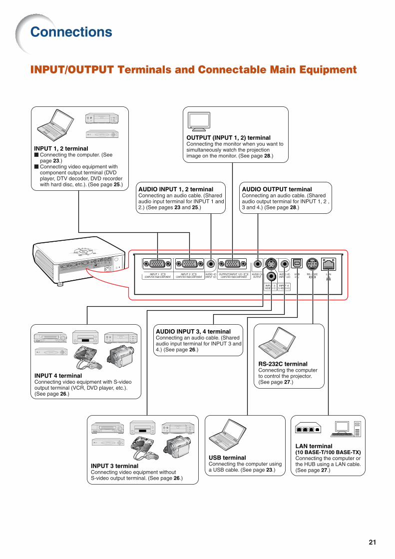
INPUT/OUTPUT Terminals and Connectable Main Equipment
INPUT 1, 2 terminalConnecting the computer. (See page 23.)Connecting video equipment with component output terminal (DVD player, DTV decoder, DVD recorder with hard disc, etc.). (See page 25.)
INPUT 3 terminalConnecting video equipment without S-video output terminal. (See page 26.)
AUDIO INPUT 1, 2 terminalConnecting an audio cable. (Shared audio input terminal for INPUT 1 and 2.) (See pages 23 and 25.)
INPUT 4 terminalConnecting video equipment with S-video output terminal (VCR, DVD player, etc.).(See page 26.)
AUDIO INPUT 3, 4 terminalConnecting an audio cable. (Shared audio input terminal for INPUT 3 and 4.) (See page 26.)
OUTPUT (INPUT 1, 2) terminalConnecting the monitor when you want to simultaneously watch the projection image on the monitor. (See page 28.)
USB terminalConnecting the computer using a USB cable. (See page 23.)
RS-232C terminalConnecting the computer to control the projector. (See page 27.)
AUDIO OUTPUT terminalConnecting an audio cable. (Shared audio output terminal for INPUT 1, 2 , 3 and 4.) (See page 28.)
LAN terminal(10 BASE-T/100 BASE-TX) Connecting the computer or the HUB using a LAN cable. (See page 27.)
Connections

22
Terminal on theprojector
INPUT 1, 2
AUDIO INPUT
INPUT 1, 2
INPUT 1, 2
INPUT3
INPUT4
AUDIO INPUT
AUDIO INPUT
AUDIO OUTPUT
OUTPUT
Equipment
Computer
Audio-visualequipment
Amplifier
Monitor
Terminal onconnected equipment
RGBoutput terminal
Audiooutput terminal
Componentvideo
output terminal
Terminalfor using
thededicated
cable
Videooutput terminal
S-videooutput terminal
Audiooutput terminal
Terminalfor using
thededicated
cable
Audioinput terminal
RGB inputterminal
Cable
RGB cable (supplied)
ø3.5 mm stereo audio cable (commercially available)
3 RCA (Component) to 15-pin D-sub cable (supplied)
Connect with the cable adaptor, etc.
Video cable (commercially available)
S-video cable (commercially available)
ø3.5 mm minijack to RCA audio cable(commercially available)
Connect with the cable adaptor, etc.
ø3.5 mm minijack to RCA audio cable(commercially available)
RGB cable (commercially available)
Samples of Cables for Connection
•For more details of connection and cables, refer to the operation manual of the connecting equipment.•You may need other cables or connectors not listed below.
Cable adaptor (commercially available)
Cable adaptor(commercially available)
3 RCA (Component)to 15-pin D-sub cable(supplied)
Dedicated cable
ø3.5 mm minijack to RCA audio cable(commercially available)
Dedicated cable

23
Connecting to a Computer
Before connecting, ensure the power cord of the projector from the AC outlet is unplugged,and that the devices to be connected are turned off. After making all connections, turn on theprojector and then the other devices. When connecting a computer, ensure that it is the lastdevice to be turned on after all the connections are made.Ensure the operation manuals of the devices to be connected have been read before making connections.
To audio output terminal
To RGB output terminal
To USB terminal
* ø3.5 mm stereo or mono audio cable (commercially available)
USB cableConnect to use the remote control as a wireless computer mouse.
To USB terminalTo INPUT 1terminal
Computer
To AUDIOINPUT 1, 2 terminal
RGB cable
* When using the ø3.5 mm mono audio cable, the volume level will be half of when using the ø3.5 mm stereo audio cable.
Note•When connecting with a USB cable, you can use the remote control as a mouse for controlling the cursor.
See page 24.•See page 69 “Computer Compatibility Chart” for a list of computer signals compatible with the projector.
Use with computer signals other than those listed may cause some of the functions to not work.•A Macintosh adaptor may be required for use with some Macintosh computers. Contact your nearest
Macintosh Dealer.•Depending on the computer you are using, an image may not be projected unless the signal
output setting of the computer is switched to the external output. Refer to the computer operationmanual for switching the computer signal output settings.
“Plug and Play” function (when connecting to a 15-pin terminal) This projector is compatible with VESA-standard DDC 1/DDC 2B. The projector and a VESA DDC com-
patible computer will communicate their setting requirements, allowing for quick and easy setup. Before using the “Plug and Play” function, ensure to turn on the projector first and the connected
computer last.
Note•The DDC “Plug and Play” function of this projector operates only when used in conjunction with a VESA
DDC compatible computer.
RGB cable
USB cable
Suppliedaccessories

24
Connecting to a Computer
Using the Remote Control as the Wireless Computer Mouse
When connecting the projector and the computer with the supplied RGB cable and USBcable (see page 23), you can use the remote control as the computer mouse.
MOUSE/Adjustment button ('/"/\/|)
R-CLICK button
L-CLICK button
The mouse pointer can be operated inthe following way after it is connected.
When moving the cursorPress MOUSE/Adjustment button ('/"/\/|).
When left-clickingPress .
When right-clickingPress .
When your computer supports only aone-click mouse (such as Macintosh)Press or .
L-CLICK and R-CLICK have common func-tion.
Note
•You cannot use this function when displaying themenu screen.
•Confirm that the computer recognizes the USBconnection.
• If “Resize” is displayed when signals having ahigher resolution than XGA are being input andyou have set “Dot By Dot” as the screen size,you cannot operate the mouse function.
25
Connecting to Video Equipment
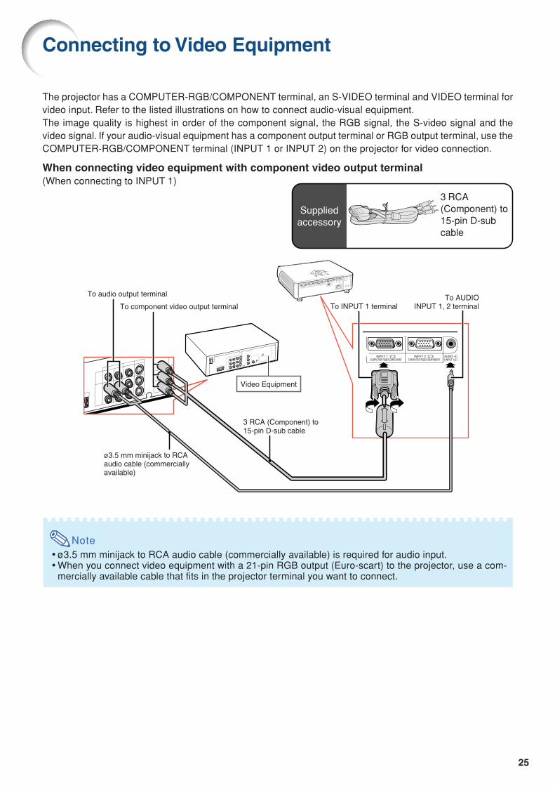
The projector has a COMPUTER-RGB/COMPONENT terminal, an S-VIDEO terminal and VIDEO terminal forvideo input. Refer to the listed illustrations on how to connect audio-visual equipment.The image quality is highest in order of the component signal, the RGB signal, the S-video signal and thevideo signal. If your audio-visual equipment has a component output terminal or RGB output terminal, use theCOMPUTER-RGB/COMPONENT terminal (INPUT 1 or INPUT 2) on the projector for video connection.
When connecting video equipment with component video output terminal(When connecting to INPUT 1)
To audio output terminal
ø3.5 mm minijack to RCAaudio cable (commerciallyavailable)
3 RCA (Component) to15-pin D-sub cable
To component video output terminal To INPUT 1 terminalTo AUDIO
INPUT 1, 2 terminal
Video Equipment
Suppliedaccessory
3 RCA(Component) to15-pin D-subcable
Note•ø3.5 mm minijack to RCA audio cable (commercially available) is required for audio input.•When you connect video equipment with a 21-pin RGB output (Euro-scart) to the projector, use a com-
mercially available cable that fits in the projector terminal you want to connect.

26
When connecting video equipment with video output terminal
When connecting video equipment with S-video output terminal
Note•ø3.5 mm minijack to RCA audio cable (commercially available) is required for audio input.•When you connect video equipment with a 21-pin RGB output (Euro-scart) to the projector, use a com-
mercially available cable that fits in the projector terminal you want to connect.
ø3.5 mm minijack to RCAaudio cable (commerciallyavailable)
To audio output terminal
To S-video output terminal
S-video cable (commercially available)
To INPUT 4 terminal
To AUDIO INPUT 3, 4 terminal
Video Equipment
ø3.5 mm minijack to RCAaudio cable (commerciallyavailable)
To audio output terminal
To video output terminal
Composite video cable (commercially available)
To INPUT 3 terminal
To AUDIO INPUT 3, 4 terminal
Video Equipment
Connecting to Video Equipment

27
Controlling the Projector by a Computer
When the RS-232C terminal on the projector is connected to a computer with a DIN-D-sub RS-232C adaptorand an RS-232C serial control cable (cross type, commercially available), the computer can be used to controlthe projector and check the status of the projector. Refer to the “SETUP GUIDE” contained on the suppliedCD-ROM for details.
When connecting to a computer using an RS-232C serial control cable and a DIN-D-sub RS-232C adaptor
Note•The RS-232C function may not operate if your computer terminal is not correctly set up. Refer to the
operation manual of the computer for details.•Refer to page 4 of the “SETUP GUIDE” contained on the supplied CD-ROM for “RS-232C Specifica-
tions and Commands”.
Info
•Do not connect the RS-232C cable to a port other than the RS-232C terminal on the computer. This maydamage your computer or projector.
•Do not connect or disconnect an RS-232C serial control cable to or from the computer while it is on. Thismay damage your computer.
When connecting to the LAN terminal using a LAN cable
Note•When connecting to hub, use straight-through Category 5 (CAT.5) type cable (commercially available).•When connecting to computer, use cross-over Category 5 (CAT.5) type cable (commercially available).
Computer
To RS-232C terminal
RS-232C serial control cable (cross type, commercially available)
To RS-232C terminal
DIN-D-subRS-232C adaptor
HUB
or
Computer
LAN cable (Category 5 type, commercially available)
To LAN terminal
TX/RX LED (yellow)Illuminates when transmitting/receiving data.LINK LED (green)Illuminates when linked.
* To ensure safety, do not connect theLAN terminal with any cables suchas a telephone line that may causeexcessive voltage.
Suppliedacces-sory
DIN-D-subRS-232Cadaptor

28
To RGB input terminal
RGB cable (commercially available)
RGB cable
To RGB output terminal
To INPUT 1 terminal To OUTPUT(INPUT 1, 2) terminal
Monitor Computer
To audio input terminal
ø3.5 mm minijack to RCA audio cable(commercially available)
To AUDIO OUTPUT terminal
Amplifier
RGB cableSuppliedaccessory
Connecting to a Monitor with RGB Input Terminal
You can display computer images on both the projector and a separate monitor using two sets of RGB cables.
Note•RGB signals and Component signals can be output to the monitor.•For this connection, another RGB cable (commercially available) is required.
Connecting to an Amplifier or Other Audio Equipment
Audio signals input from equipment connected to each audio input terminal of the projector can be output to audio equipment.
Note•ø3.5 mm minijack to RCA audio cable (commercially available) is required for audio input.•Turn off the power of both the projector and audio equipment when connecting.•When turning off the power in the case of connecting an amplifier or other audio equipment, first turn off
the power of the amplifier and then turn off the power of the projector.•By using external audio components, the volume can be amplified for better sound.•For details on Variable Audio Output (VAO) and Fixed Audio Output (FAO), see page 58.

29
Turning the Projector On/Off
Info•English is the factory preset language. If you want to
change the on-screen display to another language,change the language according to the procedure onpage 62.
Lampindicator
Powerindicator
POWER button
POWER button
On-screen Display
Info
•Do not unplug the power cord during projection or cool-ing fan operation. The cooling fan in this projector contin-ues to run for about 90 seconds after the projector entersthe standby mode. This can cause damage due to rise ininternal temperature, as the cooling fan also stops.
Power cordSuppliedaccessoryConnecting the Power Cord
Plug the supplied power cord into theAC socket on the rear of the projector.
Turning the Projector onBefore performing the steps in this section,connect any equipment that you use with theprojector. (See pages 23-28.)
Remove the lens cap and press on the
projector or on the remote control.•The power indicator illuminates red.•After the lamp indicator illuminates, the projec-
tor is ready to start operation.•When System Lock is set, the keycode input
screen appears. Enter the right keycode tostart projection. See page 54 for details.
Note•The lamp indicator illuminates or blinks, in-
dicating the status of the lamp.Green: The lamp is ready.Blinking green: The lamp is warming up
or shutting down.Red: The lamp is shut down abnor-
mally or the lamp should bereplaced.
•When switching on the projector, a slight flicker-ing of the image may be experienced within thefirst minute after the lamp has been illuminated.This is normal operation as the lamp's controlcircuitry is stabilizing the lamp output charac-teristics. This does not indicate malfunction.
• If the projector is put into standby mode andimmediately turned on again, the lamp maytake some time to illuminate.
Turning the Power off (Putting
the Projector into Standby Mode)
1 Press on the projector or on the remote control, then pressthat button again while the confir-mation message is displayed, toput the projector into standbymode.
2 Unplug the power cord from the ACoutlet after the cooling fan stops.

30
Rear adjustment feet
Image Projection
Front adjustmentfootHEIGHT ADJUST button
Side View
Lens center
Top View
Using the AdjustmentFeetThe height of the projector can be adjustedusing the adjustment feet at the front and rearof the projector when the screen is locatedhigher than the projector, the screen is inclinedor when the installation site is slightly inclined.Install the projector so that it is as perpen-dicular to the screen as possible.
1 Press the HEIGHT ADJUST button.•The front adjustment foot comes out.
2 Lift the projector to adjust itsheight while pressing theHEIGHT ADJUST button.•The projector is adjustable up to approxi-
mately 12 degrees (6 steps).•When lowering the projector, it may be
difficult to move the front adjustment footbecause the installation surface is diffi-cult to slide. In this case, pull the pro-jector back slightly and adjust its height.
3 Remove your hand from theHEIGHT ADJUST button of theprojector after its height hasbeen finely adjusted.
4 Finely adjust the height and in-clination by turning the rear ad-justment feet.•When adjusting the height of the pro-
jector, trapezoidal distortion occurs.When “Auto Keystone” of the “Options2”menu is set to “ ” (ON) (see page 57),keystone correction functions automati-cally to correct trapezoidal distortion.When you want to adjust the automati-cally corrected image, use the manualkeystone correction. (See page 31.)
Info
•Do not press the HEIGHT ADJUST buttonwhen the front adjustment foot comes outwithout firmly holding the projector.
•Do not hold the lens when lifting or lower-ing the projector.
•When lowering the projector, be careful notto get your fingers caught in the area be-tween the adjustment foot and the projector.

31
"On-screen Display (Keystone Correction mode)
MOUSE/Adjustment button ('/"/\/|)
UNDObutton
KEYSTONEbutton
Compresseslower side.
Compressesupper side.
Note
•The Manual Keystone Correction can be ad-justed up to an angle of approximately ±35degrees and the screen can also be set upto an angle of approximately ±35 degrees(when the resize mode is set to “NORMAL”(see page 36)).The screen can also be installed by inclin-ing to that angle.
•The Keystone Correction cannot be ad-justed in the lateral direction.
•You can use the same settings used inNORMAL mode 4:3 for 16:9.
Correcting TrapezoidalDistortionAuto Keystone Correction
When the image is projected either from the topor from the bottom towards the screen at anangle, the image becomes distorted trapezoidally.The function for correcting trapezoidal distortionis called Keystone Correction.This projector is equipped with an “Auto KeystoneCorrection” function that automatically correctsany trapezoidal distortion within the projected im-age. The correction is made automatically providedthe vertical incline or decline is within 12 degrees.
Note
•When not using the Auto Keystone Correc-tion function, set “Auto Keystone” on the“Options2” menu to “ ” (OFF).
Manual Keystone CorrectionWhen you want to make fine adjustments after theAuto Keystone Correction function has been activated,or when you want to make corrections without usingthe Auto Keystone Correction function, you can makecorrections manually using the following procedure.
1 Press on the remote control toenter the Keystone Correction mode.•You can also use on the
projector.
2 Press ', | or ", \ on the re-mote control to adjust the Key-stone Correction.•You can also adjust the Keystone Cor-
rection using the ''''', ||||| or """"", \\\\\ buttonson the projector.
Note
•Press to return to the default setting.•Straight lines or the edges of images may
appear jagged while adjusting the image.
3 Press .•The on-screen display of the Keystone
Correction mode will disappear.•You can also use on the
projector.

32
Adjusting the FocusThis projector is equipped with an “Auto Focus”function that adjusts the focus automaticallywhen it is turned on. When you want to readjustthe focus after the Auto Focus function has beenactivated, you can operate the Auto Focus func-tion using the following procedure.
Press on the projector or on the remote control.•The focus is adjusted automatically after the
focus pattern is displayed, and the focus pat-tern disappears from the screen.
Note
•Auto Focus can be performed over a rangeof 40 to 100 inches.
•The ability to adjust the focus automaticallydepends on the screen conditions and thesurrounding brightness.
•Adjust the focus manually when the focusis not adjusted with Auto Focus or when youwant to make fine adjustments.
•When not using the Auto Focus function,set “Auto Focus” on the “Options2” menu to“ ” (OFF).
Adjusting the Projected Image SizeWhen adjusting zoom using the buttons
on the projector on the remote control
Image Projection
ZOOM-FOCUS button
AUTO FOCUS button
Adjustment buttons('/"/\/|)
Auto focus sensorAuto focus may not function normally if there is an obstruction between the auto focus sensor and the screen, or if there is dirt or dust on the auto focus sensor. Remove any obstructions, dirt or dust.
ZOOM buttons
FOCUS buttons
AUTO FOCUS button
1 Press .
2 Adjust by pressing \ or |.
Note
•Manually adjusting the focus or zoomAfter you have pressed the FOCUS buttonsor ZOOM buttons on the remote control, orafter you have pressed the ZOOM-FOCUSbutton on the projector, you can display thetest pattern by pressing the ENTER button.The test pattern is useful for making moreaccurate adjustments.
Adjust by pressing theFOCUS buttons.
Adjust by pressing theZOOM buttons.
1 Press .
2 Adjust by pressing ' or ".
When adjusting the focus using the buttons
on the projector on the remote control

33
Switching the INPUTModeSelect the appropriate input mode for the con-nected equipment.
Press , , or on the re-mote control to select the input mode.•••••When pressing ''''' or """"" on the projector, input
mode switches in order of :
INPUT 1 INPUT 2 INPUT 3 INPUT 4
Note
•When no signal is received, “NO SIGNAL”will be displayed. When a signal that theprojector is not preset to receive is received,“NOT REG.” will be displayed.
•The INPUT mode is not displayed when“OSD Display” of the “Options1” menu is setto “ ” (OFF). (See page 51.)
About the INPUT mode
Adjusting the VolumePress \\\\\/||||| on the projector or VOL
/ on the remote control to ad-just the volume.
Note
•Pressing or \ will lower the volume.Pressing or | will raise the volume.
"On-screen Display of INPUT Mode (Example)
Using RGB
UsingComponent
INPUT 1/2 mode
INPUT 4 mode Using S-Video
INPUT 3 mode Using Video
Used for projecting images fromequipment that sends RGB sig-nals or component signals con-nected to the RGB input terminal.
Used for projecting imagesfrom equipment connected tothe VIDEO input terminal.
Used for projecting imagesfrom equipment connected tothe S-VIDEO input terminal.
INPUT 1/INPUT 2(RGB/Component)
INPUT 3(Video)
INPUT 4(S-Video)
INPUT buttons / / /
Volume buttons
"On-screen Display

34
×1 ×4 ×9 ×16 ×36 ×64×2 ×3
Image Projection
AV MUTE button
"On-screen Display
MOUSE/Adjustment button ('/"/\/|)
ENLARGE(Enlarge/Reduce)buttons
UNDO button
RESIZE button
Displaying the BlackScreen and Turning offthe Sound TemporarilyPress on the remote control to temporarilydisplay a black screen and turn off the sound.
Note
•Pressing again will turn the projectedimage and sound back on.
Displaying an EnlargedPortion of an ImageGraphs, tables and other portions of projectedimages can be enlarged. This is helpful whenproviding more detailed explanations.
1 Press on the remote control.•Enlarges the image.
•Pressing or enlarges or reduces
the projected image.
Note
•You can change the location of the en-larged image using ', ", \ and |.
2 Press on the remote controlto cancel the operation.•The magnification then returns to ×1.
NoteIn the following cases, the image willreturn to the normal size (×1).•When switching the INPUT mode.
•When has been pressed.
•When the input signal is changed.•When the input signal resolution and re-
fresh rate (vertical frequency) change.•When has been pressed.

35
Freezing a MovingImage
1 Press on the remote control.•The projected image is frozen.
2 Press again to return to themoving image from the currentlyconnected equipment.
Selecting the PictureModeYou can select the suitable picture mode for theprojected image, such as movie or video game.
Press on the remote control.•When pressing , the picture mode changes
in order of
Note
•Press to return to the “STANDARD” mode.
•This function can also be accessed from theOSD menu (see page 44).
Switching the HighBrightness/High ContrastModeThis function controls the quantity of the pro-jected light and the contrast of the image.
Press on the remote control.•The mode is switched between “HIGH
BRIGHTNESS MODE” and “HIGH CON-TRAST MODE”.
Note
•This function can also be accessed from theOSD menu (see page 46).
STANDARD PRESENTATION CINEMA GAME
FREEZE button
PICTURE MODE button
UNDO button
IRIS button

36
Resize Mode
Press on the remote control.•Pressing changes the display as shown on
pages 36 and 37.•To return to the standard image, press while
“RESIZE” is displayed on the screen.•This function can also be accessed from the OSD
menu (see page 50).
This function allows you to modify or customize the resize mode to enhance the input image. Depend-ing on the input signal, you can choose “NORMAL”, “DOT BY DOT”, “BORDER” or “STRETCH” image.
COMPUTER
STRETCH
Output screen imageInput Signal
Image type NORMAL DOT BY DOT BORDER
4:3 aspect ratio
4:3 aspect ratio
4:3 aspect ratio
5:4 aspect ratio
16:9 aspect ratio
: Cutout area on which images cannot be projected.: Area where the signals are off screen.
* Mode for projecting an image with the original aspect ratio without cutting any portions.
* * *
* *
* *
* *
*
Computer
Resolutionlower than
XGA
XGA
Resolutionhigher than
XGA
1280 × 720
SXGA (1280 × 1024)
4:3 aspect ratio
Other aspect ratios
SVGA (800 × 600)
XGA (1024 × 768)
SXGA (1280 × 960)
SXGA+ (1400 × 1050)
SXGA (1280 × 1024)
1280 × 720
1024 × 768
960 × 768
—
800 × 600
—
1280 × 960
1400 × 1050
1280 × 1024
—
768 × 576
720 × 576
—
1024 × 576
960 × 576
1024 × 576
NORMAL DOT BY DOT BORDER STRETCH
RESIZE button
MOUSE/Adjustment button ('/"/\/|)
UNDO button
Image Projection
Note• If “RESIZE” is displayed when you have set “DOT BY DOT” and signals having a higher resolution than XGA are
being input, you can move the image so that it appears entirely within the panel by using the adjustment buttons('/"/\/|) on the remote control. (However, this does not apply when you have set “Resize” from the OSD menu.)

37
VIDEO
• “STRETCH” is fixed when 540P, 720P or 1080I signals are entered.
4:3 aspect ratio
Letter box
Squeezed 16:9 image
Squeezed 4:3 image
16:9 aspect ratio
16:9 aspect ratio(4:3 aspect ratio in
16:9 screen)
Output screen imageInput Signal
Image typeDVD / Video
480I, 480P,NTSC, PAL, SECAM
540P, 720P,1080I (16:9)
: Cutout area on which images cannot be projected.: Area on which the image is not included in the original signals.
* Mode for projecting an image with the original aspect ratio without cutting any portions.
* *
*
*
*
*
*
*
BORDER STRETCHNORMAL

38
Menu Items
The following shows the items that can be set in the projector.
Note
When using the INPUT 1 or INPUT 2 mode:• “Fine Sync” menu is only displayed when the projector input is INPUT 1 or INPUT 2.
“Picture” menu
“Fine Sync” menu
INPUT 1 (RGB) / INPUT 2 (RGB)
INPUT 1 (Component) / INPUT 2 (Component)INPUT 3 / INPUT 4
INPUT 1 / INPUT 2
+30-30
+30-30
+30-30
+30-30
+30-30
+30-30
+100
Signal Type AutoRGBComponent
Tint
Color
IRIS
Reset
Sharp
Bright
+30-30Contrast
Red
Blue
Bright Boost
sRGB [ON/OFF]
Picture
High BrightnessHigh Contrast
5500K6500K7500K8500K9300K10500K
Main Menu Sub Menu
CLR Temp
Page 44
Page 45
Page 44
Page 44
Page 45
Page 46
Page 44
Page 46
Page 47
Picture Mode StandardPresentationCinemaGame
*1
*1
*1
*2
*3
*1 Items when inputting component signal through INPUT 1 or INPUT 2, or when selecting INPUT 3 or INPUT 4
*2 Item when inputting RGB signal through INPUT 1 or INPUT 2*3 Item when selecting INPUT 1 or INPUT 2
Fine Sync
+15-15
+30-30
+30-30
+30-30Clock
Phase
H-Pos
V-Pos
Reset
Signal Info
Special Modes
Main Menu
Auto Sync [ON/OFF]
Page 48
Page 48
Page 48
Page 49
Page 49
*4
*4 Item when inputting RGB signal through INPUT 1 or INPUT 2

39
“Options1” menu
“Language” menu
“Options2” menu
Example: INPUT 3 / INPUT 4Lamp Timer(Life)Options1
Main Menu Sub Menu
OSD Display [ON/OFF]
AutoPALNTSC3.58SECAMNTSC4.43PAL-MPAL-NPAL-60
Video System
Background LogoBlueNone
NormalBorderDot By DotStretch
Eco Mode [Eco/Standard]
Auto Power Off [ON/OFF]
System Lock
CenterUpper RightLower RightUpper LeftLower Left
Menu Position
Page 50
Page 51
Page 50Resize
Page 50
Page 51
Page 52
Page 52
Page 53
Page 53
Pages 54 and 55
*2
*1
*1 Item when inputting RGB signal through INPUT 1 or INPUT 2*2 Item when selecting INPUT 3 or INPUT 4
Main Menu
EnglishDeutschEspañolNederlandsFrançaisItalianoSvenskaPortuguês
Language
Page 62
LAN/RS232C
Monitor Out
RS-232C
Options2
EnableDisable
FrontCeiling + FrontRearCeiling + Rear
9600 bps115200 bps
EnableDisable
Main Menu Sub Menu
PRJ Mode
Page 56 Page 56
Page 59
FAOVAO
Audio Out
Page 58
Page 59
IP Address
Page 61
Projector
Page 61
Auto Focus [ON/OFF]
Page 57Auto Keystone [ON/OFF]
Page 57
Page 60
Page 60
Page 61
Password Old PasswordNew PasswordReconfirm
Speaker [ON/OFF]
Page 58
All Reset
Page 61
MAC Address

40
The menu can be operated to achieve two functions, adjustments and settings. (For settingthe menu items, see pages 42 and 43. )
Using the Menu Screen
Menu Selections (Adjustments)Example: Adjusting “Bright”•This operation can also be performed by using the buttons on the projector.
Menu icons
ENTER button
MENU button
UNDO button
MOUSE/ Adjustmentbutton ('/"/\/|)
Adjustment buttons ('/"/\/|)
MENU button
ENTER button
Example: “Picture” screen menu forINPUT 1 (RGB) mode
1 Press .•The “Picture” menu screen for the se-
lected input mode is displayed.
2 Press ||||| or \\\\\ to display the othermenu screens.•The menu icon for the selected menu
screen is highlighted.
Note
•The “Fine Sync” menu is not availablefor selecting INPUT 3 or INPUT 4.
Menu icon Menu screen
Picture
Fine Sync
Options1
Options2
Language
41
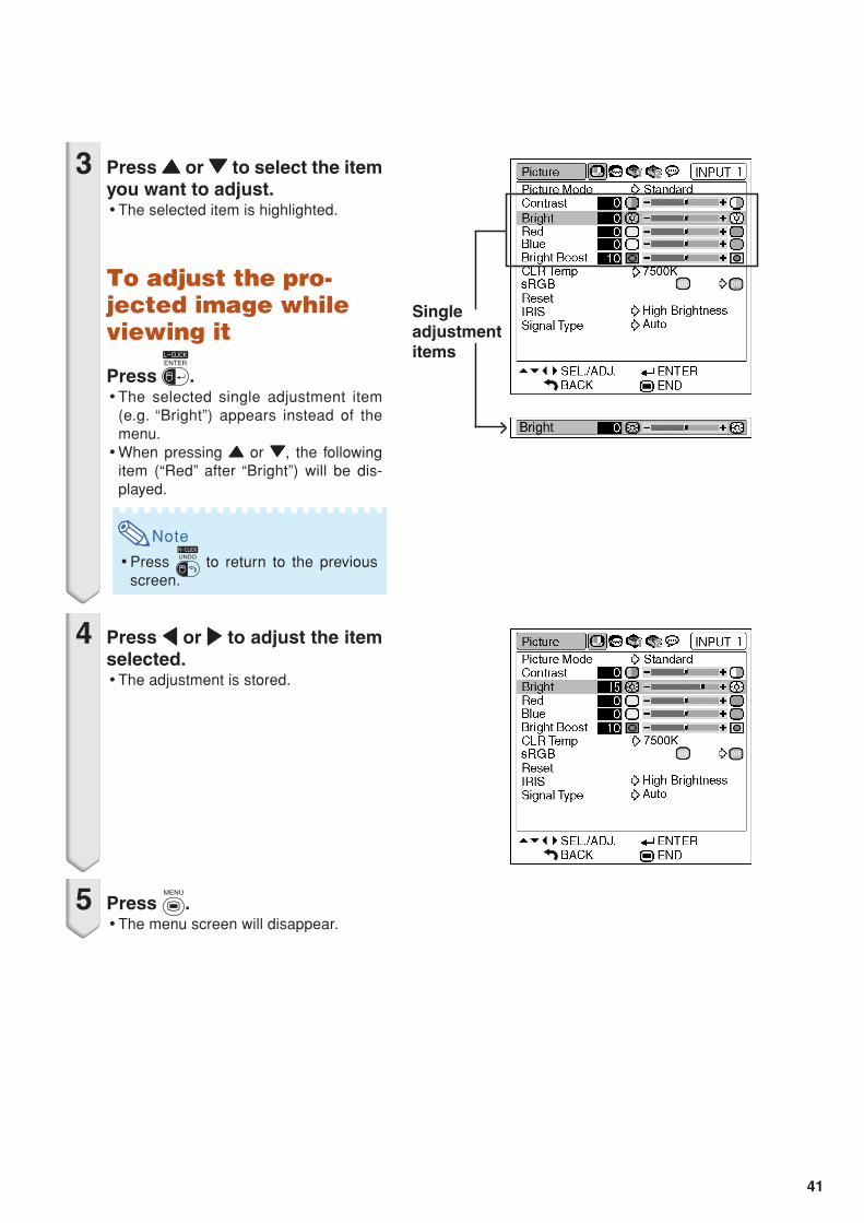
3 Press ''''' or """"" to select the itemyou want to adjust.•The selected item is highlighted.
To adjust the pro-jected image whileviewing it
Press .•The selected single adjustment item
(e.g. “Bright”) appears instead of themenu.
•When pressing ''''' or """"", the followingitem (“Red” after “Bright”) will be dis-played.
Note
•Press to return to the previousscreen.
4 Press \\\\\ or ||||| to adjust the itemselected.•The adjustment is stored.
5 Press .•The menu screen will disappear.
Singleadjustmentitems

42
MOUSE/ Adjustment button('/"/\/|)
ENTER button MENU button
UNDO button
Menu Selections (Settings)Example: Setting “Menu Position”•This operation can also be performed by using the buttons on the projector.
Menu icons
Example: “Options1” screen menu
The menu can be operated to achieve two functions, adjustments and settings. (For adjust-ing the menu items, see pages 40 and 41.)
Example: “Picture” screen menu forINPUT 1 (RGB) mode
1 Press .•The “Picture” menu screen for the
selected input mode is displayed.
2 Press ||||| or \\\\\ to display the othermenu screens.•The menu icon for the selected menu
screen is highlighted.
Note
•The “Fine Sync” menu is not availablefor selecting INPUT 3 or INPUT 4.
Using the Menu Screen
Menu icon Menu screen
Picture
Fine Sync
Options1
Options2
Language

43
Sub menu
3 Press ''''' or """"" to select theitem you want to set, and thenpress ||||| to display the sub menu.•The selected item is highlighted.•When you select “System Lock” on the
“Options1” menu or “Password” on the
“Options2” menu, press .
Note
•Press or \ to return to the previ-ous screen.
•For some items, press \ or | to se-lect the icon using “ ”.
4 Press ''''' or """"" to select the set-ting of the item displayed in thesub menu.
5 Press .•The selected item is set.
6 Press .•The menu screen will disappear.

44
You can adjust the projector’s picture to your preferences using the “Picture” menu.
Picture Adjustment (“Picture” menu)
Selecting the Picture ModeThis function allows you to select the picturemode in accordance with brightness of the roomor content of the image to be projected.In all picture modes, items on the “Picture” menucan be adjusted and saved.
Menu operation Page 42
Example: “Picture” screen menu for IN-PUT 1 (RGB) mode
Description of Picture Modes
Note
•You can also press on the remote controlto select the picture mode. (See page 35.)
Adjusting the ImageSelect a picture mode before adjusting the im-age.
Menu operation Page 40
Example: “Picture” screen menu for IN-PUT 1 (RGB) mode
Description of Adjustment Items
*1 “Color”, “Tint” and “Sharp” are not displayed whenselecting INPUT 1/INPUT 2 and setting the “Sig-nal Type” to “RGB” or setting the “Signal Type” to“Auto” and the input signal is recognized as anRGB signal.
*2 “Red” and “Blue” cannot be adjusted when “sRGB”is set to “ ” (ON).
Note
• “Sharp” can be adjusted when 480I, 480P, 540P,576I, 576P, 720P, 1035I or 1080I signals aredetected while “Signal Type” for INPUT 1 or IN-PUT 2 is set to “Component” or set to “Auto”and the input signal is recognized as a compo-nent signal.
•To reset all adjustment items, select “Reset” and
press .
Selectable itemsStandardPresentation
Cinema
Game
DescriptionFor standard imageBrightens darker portions of image formore enhanced presentations.Gives greater depth to darker portionsof image for a more exciting theaterexperience.For natural color gradation for playing agame, etc.
Selectable items Press \\\\\ Press |||||ContrastBrightColor*1
Tint*1
Sharp*1
Red*2
Blue*2
For less contrastFor less brightnessFor less color intensityFor making skin tones purplishFor less sharpnessFor weaker redFor weaker blue
For more contrastFor more brightnessFor more color intensityFor making skin tones greenishFor more sharpnessFor stronger redFor stronger blue

45
Emphasizing the ContrastThis function emphasizes the bright portions ofimages to obtain a higher contrast image.
Menu operation Page 40
Example: “Picture” screen menu for IN-PUT 1 (RGB) mode
Description of Bright Boost Setting
Note
• “Bright Boost” cannot be set when “sRGB” isset to “ ” (ON).
Adjusting the Color TemperatureMenu operation Page 42
Example: “Picture” screen menu for IN-PUT 1 (RGB) mode
Description of Color Temperature Settings
Note
•Values on “CLR Temp” are only for general stan-dard purposes.
• “CLR Temp” cannot be set when “sRGB” is setto “ ” (ON).
Selectable items5500K6500K7500K8500K9300K10500K
DescriptionFor lower color temperature for warmer,reddish incandescent-like images.
For higher color temperature for cooler,bluish, fluorescent-like images.
Description
To improve colorreproduction, lowerbright boost setting.
To increase brightness,increase bright boostsetting.

46
Switching the High Bright-ness/High Contrast ModeThis function changes the brightness and con-trast of the projected image. It can be operatedusing the IRIS button on the remote control.
Menu operation Page 42
Example: “Picture” screen menu for IN-PUT 1 (RGB) mode
Description of IRIS SettingsSelectable itemsHigh Brightness
High Contrast
DescriptionHigh brightness is given priority overhigh contrast.High contrast is given priority over highbrightness.
Picture Adjustment (“Picture” menu)
sRGB SettingWhen you want to display the image in a naturaltint based on an original image from the com-puter, select “sRGB” and set it to “ ” (ON).
Menu operation Page 42
Example: “Picture” screen menu for IN-PUT 1 (RGB) mode
Note
•An international standard of color reproductionregulated by the IEC (International ElectrotechnicalCommission). As the fixed color area has beendecided by the IEC, the images are displayed in anatural tint based on an original image, when“sRGB” is set to “ ” (ON).
•You cannot set the items, “Red”, “Blue”, “CLRTemp”, “Bright Boost” on the “Picture” menu,when “sRGB” is set to “ ” (ON).
•For additional information about the sRGB func-tion, visit “http://www.srgb.com/”.
Info
•When “sRGB” is set to “ ” (ON), the projectedimage may become dark, but this does not indi-cate a malfunction.

47
Signal Type SettingThis function allows you to select the input sig-nal type RGB or Component for INPUT 1 or IN-PUT 2.
Menu operation Page 42
Example: “Picture” screen menu for IN-PUT 1 (RGB) mode
Description of Signal Type SettingsDescription
Input signals are automatically recog-nized as RGB or Component.Set when RGB signals are received.Set when Component signals arereceived.
Selectable itemsAuto
RGBComponent

48
You can adjust the computer image, match the computer display mode, and confirm theinput signal using the “Fine Sync” menu.
Computer Image Adjustment (“Fine Sync” menu)
Adjusting the ComputerImageUse the Fine Sync function in case of irregulari-ties such as vertical stripes or flickering in por-tions of the screen.
Menu operation Page 40
Example: “Fine Sync” screen menu forINPUT 1 (RGB) mode
Description of Adjustment Items
Note
•You can automatically adjust the computer im-age by setting “Auto Sync” on the “Fine Sync”
menu to “ ” (ON) or pressing on the pro-
jector or on the remote control. See nextpage for details.
•To reset all adjustment items, select “Reset” and
press .
Special Modes SettingOrdinarily, the type of input signal is detected andthe correct resolution mode is automatically se-lected. However, for some signals, the optimalresolution mode in “Special Modes” on the “FineSync” menu may need to be selected to matchthe computer display mode.
Menu operation Page 42
Example: “Fine Sync” screen menu forINPUT 1 (RGB) mode
Note
• If your computer displays patterns which repeatevery other line (horizontal stripes), flickeringmay occur which makes the image hard to see.
•See “Checking the Input Signal” on the nextpage for information on the currently selectedinput signal.
Selectable itemsClockPhase
H-Pos
V-Pos
DescriptionAdjusts vertical noise.Adjusts horizontal noise (similar totracking on your VCR).Centers the on-screen image bymoving it to the left or right.Centers the on-screen image bymoving it up or down.

49
Auto Sync AdjustmentUsed to automatically adjust a computer image.
Menu operation Page 42
Example: “Fine Sync” screen menu forINPUT 1 (RGB) mode
Description of Auto Sync Adjustment
Note
•Auto Sync adjustment is also performed by
pressing on the projector or on the re-mote control.
•The Auto Sync adjustment may take some timeto complete, depending on the image of thecomputer connected to the projector.
•When the optimum image cannot be achievedwith Auto Sync adjustment, use manual adjust-ments. (See page 48.)
Checking the Input SignalMenu operation Page 42
Example: “Fine Sync” screen menu forINPUT 1 (RGB) mode
Note
•The projector will display the number of scannedlines available from audio-visual equipmentsuch as a DVD player or Digital Video.
•The projector will display the resolution whenconnecting the computer.
Selectable items
(ON)
(OFF)
DescriptionAuto Sync adjustment will occur whenthe projector is turned on or when theinput signals are switched, whenconnected to a computer.Auto Sync adjustment is not automati-cally performed.

50
You can use the “Options1” menu to enhance the usage for the projector.
Checking the Lamp LifeStatusYou can confirm the cumulative lamp usage timeand the remaining lamp life (percentage).
Menu operation Page 42
Example: “Options1” screen menu forINPUT 1 (RGB) mode
Description of Lamp Timer (Life)
Note
• It is recommended that the lamp be changedwhen the remaining lamp life becomes 5%.
•The table above indicates rough estimates in thecase of using only in each mode shown.
•Remaining lamp life changes within the range ofthe values shown depending on the frequency atwhich “Eco Mode” is switched to “ ” (Ecomode) and “ ” (Standard mode). (See page52.)
•The lamp life may vary depending on the usagecondition.
Using the “Options1” Menu
Lamp usage condition“Life”
Operated exclusivelyin Eco mode ( )Operated exclusivelyin Standard mode ( )
Remaining lamp life100% 5%
Approx. Approx.3,000 hours 150 hours
Approx. Approx.2,000 hours 100 hours
Setting the Resize ModeDepending on the input signal, you can selectthe screen image.
Menu operation Page 42
Example: “Options1” screen menu forINPUT 1 (RGB) mode
Selectable items of Resize Modes•Normal• Border•Dot By Dot*
• Stretch
*Item when inputting RGB signal through INPUT 1 orINPUT 2
Note
•For details of the Resize mode, see pages 36and 37.
•You can also press on the remote control toset the resize mode. (See page 36.)

51
Setting the Video SystemThe video input system mode is factory presetto “Auto”; however, a clear picture from the con-nected audio-visual equipment may not be re-ceived, depending on the video signal difference.In that case, switch the video signal.
Menu operation Page 42
Example: “Options1” screen menu forINPUT 3 (Video) mode
Description of Video Systems
Note
•The video signal can only be set in INPUT 3 orINPUT 4 mode.
•When “Video System” is set to “Auto”, you maynot receive a clear picture due to signal differ-ences. Should this occur, switch to the videosystem of the source signal.
DescriptionWhen connected to PAL video equipment.When connected to SECAM video equipment.When reproducing NTSC signals in PALvideo equipment.When connected to NTSC video equipment.
Selectable itemsPALSECAMNTSC4.43
NTSC3.58
Setting On-screen DisplayThis function allows you to turn the on-screenmessages on or off.
Menu operation Page 42
Example: “Options1” screen menu forINPUT 1 (RGB) mode
Description of OSD Display SettingsDescription
All On-screen Displays are displayed.
INPUT/VOLUME/AV MUTE/FREEZE/AUTO SYNC/ENLARGE/ “An invalidbutton has been pressed.” are notdisplayed.
Selectable items
(ON)
(OFF)

52
Eco ModeMenu operation Page 42
Example: “Options1” screen menu forINPUT 1 (RGB) mode
Description of Eco Mode
Note
•When “Eco Mode” is set to “ ” (Eco mode),
the power consumption will decrease and thelamp life will extend. (Projection brightness de-creases 13%.)
Brightness
87%
100%
Selectable items
(Eco mode)
(Standard mode)
Power consumption(When using AC 100V)
320 W
370 W
Lamp life
Approx.3,000 hoursApprox.2,000 hours
Selecting a Startup andBackground Image
Menu operation Page 42
Example: “Options1” screen menu forINPUT 1 (RGB) mode
Description of Background Images
Note
* If the input signal has interference, the screenwill be displayed during interference.
Selectable itemsLogo
Blue
None
DescriptionDefault image
Blue screen
Black screen*
Using the “Options1” Menu

53
Auto Power Off FunctionMenu operation Page 42
Example: “Options1” screen menu forINPUT 1 (RGB) mode
Description of Auto Power Off
Note
•When the Auto Power Off function is set to “ ”(ON), 5 minutes before the projector enters thestandby mode, the message “Enter STANDBYmode in X min.” will appear on the screen toindicate the remaining minutes.
DescriptionThe projector automatically enters thestandby mode when no input signal isdetected for 15 minutes or longer.The Auto Power Off function will bedisabled.
Selectable items
(ON)
(OFF)
Selecting the Menu ScreenPositionSelect “Menu Position” on the “Options1” menuand the desired position for the menu screen.
Menu operation Page 42
Example: “Options1” screen menu forINPUT 1 (RGB) mode
Description of Menu Positions
DescriptionDisplayed on the center of the image.Displayed on the upper right of the image.Displayed on the lower right of the image.Displayed on the upper left of the image.Displayed on the lower left of the image.
Selectable itemsCenterUpper RightLower RightUpper LeftLower Left

54
Note
• If you input a wrong keycode, the cursor returnsto the first point of the “Old Code”.
•The preset keycode is 4 " buttons on the projec-tor. If this keycode is set, the keycode input screendoes not appear when turning the power on.
3 Press the 4 buttons on the remotecontrol or on the projector to enterthe new keycode in “New Code”.
Note
•You cannot use the following buttons forkeycode:• POWER button• L-CLICK/ENTER button• R-CLICK/UNDO button• MENU button• AUTO FOCUS button• ZOOM-FOCUS button• ZOOM buttons• FOCUS buttons
•System Lock function recognizes each but-ton on the remote control or on the projec-tor as an individual button, even if they sharethe same button name. If you set the keycodewith the buttons on the projector, use onlythose buttons on the projector. If you set thekeycode with the buttons on the remote con-trol, use only those buttons on the remotecontrol.
4 Enter the same keycode in“Reconfirm”.
Note
Not displaying the keycode input screenwhen turning the projector on•Press " on the projector for four times in steps
2 and 3 above.
When the System Lock is set•When System Lock is set, the keycode input
screen appears after the power is turned on.When it appears, enter the right keycode to startprojection. Failure to enter the keycode willcause images not to be projected even whensignals are entered to the projector.
System Lock FunctionThis function prevents unauthorized use of the pro-jector. Once this function is activated, users must enterthe correct keycode each time the projector is turnedon. We suggest you record the keycode in a safe placewhere only authorized users have access.
Info• If you lose or forget your keycode, contact your
nearest EIKI Authorized Projector Dealer or Ser-vice Center. Even if the product warranty is valid,the keycode reset will incur a charge.
Menu operation Page 42
Example: “Options1” screen menu forINPUT 1 (RGB) mode
Setting the keycode
1 Select “System Lock” on the “Op-
tions1” menu, then press .•A message is displayed.•Read this message, and press .
2 Press the 4 buttons on the remotecontrol or on the projector to enterthe preset keycode in “Old Code”.•When setting the keycode for the first time,
press " on the projector for four times."""""On-screen Display
Using the “Options1” Menu

55
Changing the keycode
1 Press the buttons on the remotecontrol or on the projector to enterthe preset keycode in “Old Code”.
2 Press the 4 buttons on the remotecontrol or on the projector to enterthe new keycode in “New Code”.
3 Enter the same keycode in “Recon-firm”.
When System Lock is setIf you have set the system lock, enter thekeycode and follow the procedure below torelease the system lock.
Input screen for keycode
Note
•When System Lock is set, the keycode inputscreen appears after the power is turned on.
• If no keycode is entered, the image will not bedisplayed, even if the projector receives the in-put signal.
1 Press on the remote control or
on the projector to turn on theprojector.
2 When the keycode input screen ap-pears, enter the right keycode tostart projection.
Note
•System Lock function recognizes each buttonon the remote control or on the projector asan individual button, even if they share thesame button name. If you set the keycode withthe buttons on the projector, use only thosebuttons on the projector. If you set the keycodewith the buttons on the remote control, useonly those buttons on the remote control.

56
Helpful Functions Set during Installation (“Options2” menu)
Setting a Password••••• There is no factory preset for the password, so
the “Options2” menu is enabled.••••• If you do not want others to operate the “Op-
tions2” menu, set a password.
Menu operation Page 42
Example: “Options2” screen menu
1 Select “Password” from the “Op-tions2” menu, and press .• The screen for entering the password is displayed.
2 Press ''''' or """"" to set the first digit in“New Password” and then press |||||.
3 Enter the remaining 3 digits and
press .
4 Enter the same password in “Re-
confirm” and press .
Note
•The password must be entered to use the “Op-tions2” menu when a password has been set.
Changing the Password
1 Press ''''', """"" and ||||| to enter thepassword in “Old Password” andpress .
2 Press ''''', """"" and ||||| to set the newpassword in “New Password” andpress .
3 Enter the same 4-digit password in
“Reconfirm” and press .
Note
• If you do not want to set a password, leave the
fields blank in steps 2 and 3 and press .
•To cancel the password settings, press .
If You Forget Your PasswordIf you forget the password, delete it using the fol-lowing procedure and set a new password.
Note
•You can only use the buttons on the projectorto delete the password.
Press .
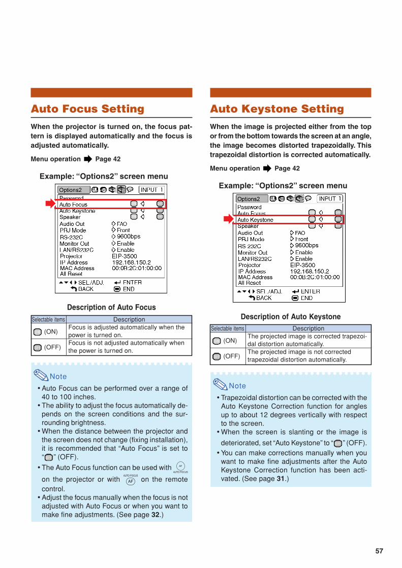
57
Auto Focus SettingWhen the projector is turned on, the focus pat-tern is displayed automatically and the focus isadjusted automatically.
Menu operation Page 42
Example: “Options2” screen menu
Description of Auto Focus
Note
•Auto Focus can be performed over a range of40 to 100 inches.
•The ability to adjust the focus automatically de-pends on the screen conditions and the sur-rounding brightness.
•When the distance between the projector andthe screen does not change (fixing installation),it is recommended that “Auto Focus” is set to“ ” (OFF).
•The Auto Focus function can be used with
on the projector or with on the remotecontrol.
•Adjust the focus manually when the focus is notadjusted with Auto Focus or when you want tomake fine adjustments. (See page 32.)
Selectable items
(ON)
(OFF)
DescriptionFocus is adjusted automatically when thepower is turned on.Focus is not adjusted automatically whenthe power is turned on.
Auto Keystone SettingWhen the image is projected either from the topor from the bottom towards the screen at an angle,the image becomes distorted trapezoidally. Thistrapezoidal distortion is corrected automatically.
Menu operation Page 42
Example: “Options2” screen menu
Description of Auto Keystone
Note
•Trapezoidal distortion can be corrected with theAuto Keystone Correction function for anglesup to about 12 degrees vertically with respectto the screen.
•When the screen is slanting or the image is
deteriorated, set “Auto Keystone” to “ ” (OFF).•You can make corrections manually when you
want to make fine adjustments after the AutoKeystone Correction function has been acti-vated. (See page 31.)
Selectable items
(ON)
(OFF)
DescriptionThe projected image is corrected trapezoi-dal distortion automatically.The projected image is not correctedtrapezoidal distortion automatically.

58
Setting the Audio OutputTypeThis function determines whether the audio leveloutput from the AUDIO OUTPUT terminal is fixedor variable by linking with VOLUME.
Menu operation Page 42
Example: “Options2” screen menu
Description of Audio Out Settings
Info
•When “Audio Out” has been set to “VAO”, first makesure to lower the volume of the projector beforeturning the power on or off and when switching theinput.
DescriptionAudio output that does not vary instrength with the volume level of thesource projector.Audio output that varies in strength withthe volume level of the source projector.
Selectable itemsFAO(Fixed AudioOutput)VAO(VariableAudio Output)
Helpful Functions Set during Installation (“Options2” menu)
Speaker SettingThis function allows you to set the audio outputof the internal speaker to “ ” (ON) or “ ” (OFF)such as when the projector is connected to anexternal amplifier.
Menu operation Page 42
Example: “Options2” screen menu
Description of Speaker Settings
Selectable items
(ON)
(OFF)
DescriptionThe audio signal is output from the internalspeaker.The audio signal is not output from theinternal speaker.

59
Reversing/Inverting Pro-jected ImagesThis projector is equipped with a reverse/invertimage function that allows you to reverse or in-vert the projected image for various applications.
Menu operation Page 42
Example: “Options2” screen menu
Description of PRJ Modes
Note
•This function is used for the reversed image andceiling-mount setups. (See page 20.)
DescriptionNormal image
Inverted image
Reversed image
Reversed and inverted image
Selectable itemsFront
Ceiling + Front
Rear
Ceiling + Rear
Selecting the Transmis-sion Speed (RS-232C)Make sure that both the projector and computerare set for the same baud rate.
Menu operation Page 42
Example: “Options2” screen menu
Description of RS-232C
Note
•Refer to the “SETUP GUIDE” contained on thesupplied CD-ROM for RS-232C Specificationsand Command Settings.
•Refer to the computer’s operation manual forinstructions for setting the computer’s baud rate.
Description
Transmission speed is slow.
Transmission speed is rapid.
Selectable items
9600 bps
115200 bps
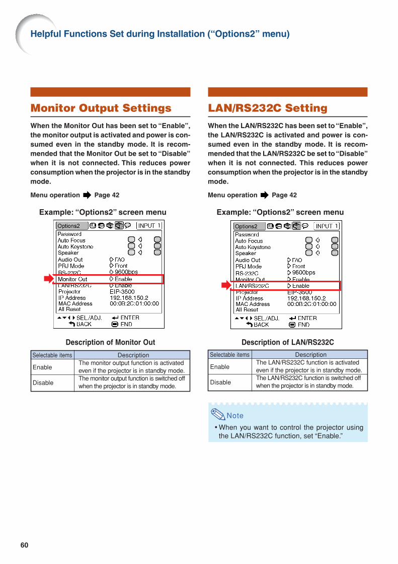
60
Monitor Output SettingsWhen the Monitor Out has been set to “Enable”,the monitor output is activated and power is con-sumed even in the standby mode. It is recom-mended that the Monitor Out be set to “Disable”when it is not connected. This reduces powerconsumption when the projector is in the standbymode.
Menu operation Page 42
Example: “Options2” screen menu
Description of Monitor Out
DescriptionThe monitor output function is activatedeven if the projector is in standby mode.The monitor output function is switched offwhen the projector is in standby mode.
Selectable items
Enable
Disable
Helpful Functions Set during Installation (“Options2” menu)
LAN/RS232C SettingWhen the LAN/RS232C has been set to “Enable”,the LAN/RS232C is activated and power is con-sumed even in the standby mode. It is recom-mended that the LAN/RS232C be set to “Disable”when it is not connected. This reduces powerconsumption when the projector is in the standbymode.
Menu operation Page 42
Example: “Options2” screen menu
Description of LAN/RS232C
Note
•When you want to control the projector usingthe LAN/RS232C function, set “Enable.”
DescriptionThe LAN/RS232C function is activatedeven if the projector is in standby mode.The LAN/RS232C function is switched offwhen the projector is in standby mode.
Selectable items
Enable
Disable

61
Returning to the DefaultSettingsThis function allows you to initialize the settingsyou have made in the projector.
Menu operation Page 42
Example: “Options2” screen menu
Note
About the network settings• “Projector” and “IP Address” on the “Options2”
menu and the network setting items describedon the “SETUP GUIDE” are initialized.
The following items or menu cannot be initialized.• “Fine Sync” menu
Special Modes• “Options1” menu
Lamp Timer (Life)System Lock
• “Language” menu
Confirming the Network In-formation for the ProjectorYou can confirm the projector name, IP addressand MAC address.
Menu operation Page 42
Example: “Options2” screen menu
Description of Network Information
Note
•For information on how to change the projectorname and IP address, see “SETUP GUIDE”contained in the supplied CD-ROM.
Displayed items
Projector
IP Address
MAC Address
DescriptionThe projector name is displayed.(Factory preset : EIP-3500)The IP address set for the projector isdisplayed.(Factory preset :192.168.150.2)The MAC address of the projector isdisplayed.
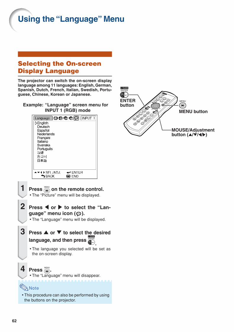
62
Selecting the On-screenDisplay LanguageThe projector can switch the on-screen displaylanguage among 11 languages: English, German,Spanish, Dutch, French, Italian, Swedish, Portu-guese, Chinese, Korean or Japanese.
Example: “Language” screen menu forINPUT 1 (RGB) mode
1 Press on the remote control.•The “Picture” menu will be displayed.
2 Press \ or | to select the “Lan-guage” menu icon ( ).•The “Language” menu will be displayed.
3 Press ' or " to select the desired
language, and then press .
•The language you selected will be set asthe on-screen display.
4 Press .•The “Language” menu will disappear.
Note
•This procedure can also be performed by usingthe buttons on the projector.
Using the “Language” Menu
ENTER button
MENU button
MOUSE/Adjustmentbutton ('/"/\/|)

63
Cleaning the lens Use a commercially available blower or lens clean-
ing paper (for glasses and camera lenses) for clean-ing the lens. Do not use any liquid type cleaningagents, as they may wear off the coating film on thesurface of the lens.
As the surface of the lens can easily get damaged,ensure not to scrape or hit the lens.
Cleaning the exhaust and intake vents Use a vacuum cleaner to clean dust from the ex-
haust vent and the intake vent.
Info
• If you want to clean the air vents during projec-
tor operation, ensure to press on the pro-
jector or on the remote control and putthe projector into standby mode. After the cool-ing fan has stopped, unplug the power cordfrom the AC socket and clean the vents.
Cleaning the projector Ensure the power cord is unplugged before cleaning
the projector. The cabinet as well as the operation panel is made
of plastic. Avoid using benzene or thinner, as thesecan damage the finish on the cabinet.
Do not use volatile agents such as insecticides onthe projector.Do not attach rubber or plastic items to the projec-tor for long periods.The effects of some of the agents in the plastic maycause damage to the quality or finish of the projector.
Wipe off dirt gently with a soft flannel cloth. When the dirt is hard to remove, soak a cloth in a
mild detergent diluted with water, wring the clothwell and then wipe the projector.Strong cleaning detergents may discolor, warp ordamage the coating on the projector. Make sure totest on a small, inconspicuous area on the projec-tor before use.
Maintenance
CleaningPaper
Mild detergentdiluted with water
WaxThinner
Mild detergent

64
Power indicatorLamp indicatorTemperature warning indicator
Maintenance Indicators
Maintenance Indicators
The warning lights on the projector indicate problems inside the projector. If a problem occurs, either the temperature indicator or the lamp indicator will illuminate red, and
the projector will enter the standby mode. After the projector has entered the standby mode, followthe procedures given below.
About the temperature warning indicator
If the temperature inside the projector increases, due to blockage of the air vents, or the setting location,
“ ” will illuminate in the lower left corner of the picture. If the temperature keeps on rising, the lamp will
turn off and the temperature warning indicator will blink, the cooling fan will run for a further 90 seconds, and
then the projector will enter the standby mode. After “ ” appears, ensure to perform the measures
described on page 65.
About the lamp indicator
When the remaining lamp life becomes 5% or less, “ ” (yellow) and “Change The Lamp.” will be
displayed on the screen. When the percentage becomes 0%, it will change to “ ” (red), the lamp will
automatically turn off and then the projector will automatically enter the standby mode. At this time,the lamp indicator will illuminate in red.
If you try to turn on the projector a fourth time without replacing the lamp, the projector will not turn on.

65
Maintenance indicatorProblem Cause Possible solution
Temperaturewarningindicator
Normal Abnormal
Off Red on(Standby)
The internaltemperature isabnormally high.
Abnormal
• Blocked air intake• Relocate the projector to an area
with proper ventilation (see page7).
• Cooling fan break-down
• Internal circuit failure• Clogged air intake
• Take the projector to your nearestEIKI Authorized Projector Dealeror Service Center for repair.
• Clean the exhaust and intakevents. (See page 63.)
Lampindicator
Red on(Standby)
The lamp doesnot illuminate.
• Burnt-out lamp• Lamp circuit failure
• Carefully replace the lamp. (Seepage 67.)
• Take the projector to your nearestEIKI Authorized Projector Dealeror Service Center for repair.
• Please exercise care whenreplacing the lamp.
Red onTime to changethe lamp.
• Remaining lamp lifebecomes 5% or less.
Green onGreen blinks
when the lampis warming up
or shuttingdown.
Info
• If the temperature warning indicator illuminates and the projector enters the standby mode, check whetherany of the ventilation holes are blocked (see page 7) and then try turning the power back on. Wait until theprojector has cooled down completely before plugging in the power cord and turning the power back on.(At least 10 minutes.)
• If the power is turned off for a brief moment due to power outage or some other cause while using theprojector, and the power supply recovers immediately after that, the lamp indicator will illuminate in redand the lamp may not be lit. In this case, unplug the power cord from the AC outlet, replace the powercord in the AC outlet and then turn the power on again.
• Do not unplug the power cord after the projector has entered the standby mode and while the cooling fanis running. The cooling fan runs for about 90 seconds.
The lamp doesnot illuminate.
• The lamp is shutdown abnormally.
• Disconnect the power cord fromthe AC outlet, and then connect itagain.

66
Lamp It is recommended that the lamp unit (optional: AH-35001) be replaced when the remaining lamp life
becomes 5% or less, or when you notice a significant deterioration in the picture and color quality.The lamp life (percentage) can be checked with the on-screen display. See page 50.
Purchase a replacement lamp unit of type AH-35001 from your place of purchase, nearest EIKI Au-thorized Dealer or Service Center.
Caution Concerning the Lamp This projector utilizes a pressurized mercury lamp. A loud sound may indicate lamp failure. Lamp
failure can be attributed to numerous sources such as: excessive shock, improper cooling, surfacescratches or deterioration of the lamp due to a lapse of usage time.The period of time up to failure largely varies depending on the individual lamp and/or the conditionand the frequency of use. It is important to note that failure can often result in the bulb cracking.
When the lamp replacement indicator and on-screen display icon are illuminated, it is recommendedthat the lamp be replaced with a new one immediately, even if the lamp appears to be operatingnormally.
Should the lamp break, the glass particles may spread inside the lamp cage or gas contained in thelamp may be vented into the room from the exhaust vent. Because the gas in this lamp includesmercury, ventilate the room well if the lamp breaks and avoid all exposure to the released gas. Incase of exposure to the gas, consult a doctor as soon as possible.
Should the lamp break, there is also a possibility that glass particles may spread inside of theprojector. In such a case, it is recommended you contact your nearest EIKI Authorized Dealer orService Center to assure safe operation.
Replacing the Lamp
Caution
• Do not remove the lamp unit from the projector right after use. The lamp will be very hot and may cause burnor injury.
• Wait at least one hour after the power cord is disconnected to allow the surface of the lamp unit to fully coolbefore removing the lamp unit.
Carefully change the lamp by following the instructions described in this section. *If you wish, youmay have the lamp replaced at your nearest EIKI Authorized Dealer or Service Center.
* If the new lamp does not illuminate after replacement, take your projector to the nearest EIKI AuthorizedDealer or Service Center for repair.
Regarding the Lamp

67
Optionalaccessory
Lamp unitAH-35001
Removing and Installingthe Lamp Unit
Info
•Ensure the lamp unit is removed using thehandle. Ensure the glass surface of thelamp unit or the inside of the projector arenot touched.
•To avoid injury to yourself and damage tothe lamp, ensure to carefully follow thesteps below.
•Do not loosen other screws except for thelamp unit cover and lamp unit.
1 Press on the projector or on the remote control to put theprojector into standby mode.•Wait until the cooling fan stops.
Warning!•Do not remove the lamp unit from the
projector right after use. The lamp andparts around the lamp will be very hotand may cause burn or injury.
2 Disconnect the power cord.•Unplug the power cord from the AC
socket.•Leave the lamp until it has fully cooled
down (about 1 hour).
3 Remove the lamp unit cover.•Turn the projector over. Loosen the user
service screw (1) that secures the lampunit cover. Pressing the tab, remove thelamp unit cover (2).
12
User service screw(for lamp unit cover)
Tab
Tab
AC socket
POWER button

68
4 Remove the lamp unit.• Loosen the securing screws from the
lamp unit. Hold the lamp unit by thehandle and pull it in the direction of thearrow. At this time, keep the lamp unithorizontal and do not tilt it.
5 Insert the new lamp unit.•Press the lamp unit firmly into the lamp
unit compartment. Fasten the securingscrews.
6 Replace the lamp unit cover.•Align the lamp unit cover and slide it to
close. Then tighten the user servicescrew to secure the lamp unit cover.
Info
• If the lamp unit and lamp unit cover are notcorrectly installed, the power will not turnon, even if the power cord is connected tothe projector.
Resetting the Lamp TimerReset the lamp timer after replacing the lamp.
Info
•Make sure to reset the lamp timer onlywhen replacing the lamp. If you reset thelamp timer and continue to use the samelamp, this may cause the lamp to becomedamaged or explode.
1 Connect the power cord.•Plug the power cord into the AC socket
of the projector.
2 Reset the lamp timer.•While simultaneously holding down ",
and on the projector, press
on the projector.
• “LAMP 0000H” is displayed, indicatingthat the lamp timer is reset.
Securing screws
Handle
User service screw(for lamp unit cover)
AC socket
POWER button
" button
ENTER button
MENU button
Regarding the Lamp

69
Note
• This projector may not be able to display images from notebook computers in simultaneous (CRT/LCD)mode. Should this occur, turn off the LCD display on the notebook computer and output the display datain “CRT only” mode. Details on how to change display modes can be found in your notebook computer’soperation manual.
• When this projector receives 640 × 350 VESA format VGA signals, “640 × 400” appears on the screen.• When projecting the RGB interlace signal using INPUT 1/2 with “Signal Type” set to “Auto” or “RGB”, the
image may not be projected as desired. In this case, select either INPUT 3 (Video) or INPUT 4 (S-Video).
Computer Compatibility Chart
•Multiple signal supportHorizontal Frequency: 15–70 kHzVertical Frequency: 43–85 HzPixel Clock: 12–108 MHzSync signal: Compatible with TTL level
DTV
Computer
27.031.537.527.031.537.927.031.527.031.537.926.231.534.737.937.543.331.435.137.946.648.146.953.735.540.348.456.560.068.755.066.267.564.064.034.937.849.760.268.7
60708560708560706070855060707275855056607072758543506070758560707560606760757575
Upscale
True
True
Intelligent Compression
Upscale
Intelligent Compression
640 × 350
640 × 400
720 × 350
720 × 400
640 × 480
800 × 600
1,024 × 768
1,152 × 864
1,280 × 1,0241,400 × 1,050
640 × 480800 × 600832 × 624
1,024 × 7681,152 × 870
MAC 13"
MAC 16"
MAC 19"MAC 21"
PC
VGA
SVGA
XGA
SXGA
SXGA+VGA
SVGA
XGASXGA
DisplayPC/MAC/WS Resolution VESA StandardVertical Frequency(Hz)
Horizontal Frequency(kHz)
15.731.533.815.631.345.028.133.828.133.8
480I480P540P576I576P720P1035I1035I1080I1080I
60606050506050605060
Signal Vertical Frequency (Hz)Horizontal Frequency (kHz)
•Compatible with sync on green signal•SXGA+ and SXGA compatible in intelligent com-
pression• Intelligent Compression and Expansion System
resizing technology
The following is a list of modes that conform to VESA. However, this projector supports other signalsthat are not VESA standards.
The table below lists signal codes that are compatible with the projector. When the images are distorted orcannot be projected, adjust the output signal of your computer and so forth while referring to the table below.

70
Troubleshooting
Check• Projector power cord is not plugged into the wall outlet.• Power to the external connected devices is off.• The selected input mode is wrong.• The AV MUTE function is working.• Cables incorrectly connected to rear panel of the projector.• Remote control batteries have run out.• External output has not been set when connecting notebook computer.• The lamp unit cover is not installed correctly.• Cables incorrectly connected to the rear panel of the projector.• “Bright” is set to minimum position.
• Image adjustments are incorrectly set.(Video Input only)• Video input system is incorrectly set.(INPUT 1, INPUT 2 only)• Input signal type (RGB/Component) is incorrectly set.
• Adjust the focus.• The projection distance exceeds the focus range.(Computer Input only)• Perform “Fine Sync” Adjustments. (“Clock” Adjustment)• Perform “Fine Sync” Adjustments. (“Phase” Adjustment)• Noise may appear depending on the computer.
• Cables incorrectly connected to rear panel of the projector.• Volume is set to minimum.
• If the picture is normal, the sound is due to cabinet shrinkagecaused by room temperature changes. This will not affectoperation or performance.
• See “Maintenance Indicators”.
Problem
An unusual sound isoccasionally heardfrom the cabinet.
Maintenanceindicator illuminates or
blinks in red.
Page29—3334
23,25-281569
67,6823,25-28
44
44
51
47
3219
4848—
23,25-2833
—
64
Sound is heard but nopicture appears.
Color is faded or poor.
Picture is blurred;noise appears.
Picture appears but nosound is heard.
No picture and no soundor projector does not start.

71
CheckProblem PagePicture is green on
INPUT 1 (COMPONENT)/INPUT 2 (COMPONENT).Picture is pink (no green)
on INPUT 1 (RGB)/INPUT 2 (RGB).
Picture is too bright andwhitish.
The cooling fanbecomes noisy.
The lamp does not lightup even after theprojector turns on.
The lamp suddenly turnsoff during projection.
The image sometimesflickers.
The lamp takes a longtime to turn on.Picture is dark.
• Change the input signal type setting.
• Image adjustments are incorrectly set.
• When temperature inside the projector increases, the coolingfan runs faster.
• The lamp indicator is illuminating in red.Replace the lamp.
• Cables incorrectly connected to the projector or the connectedequipment works improperly.
• If this happens frequently, replace the lamp.• The lamp will eventually need to be changed.
The lamp has reached the end of its life. Replace the lamp.
47
44
—
64
23,25-28
6767
This projector is equipped with a microprocessor. Its performance could be adversely affected byincorrect operation or interference. If this should happen, unplug the projector and plug it in againafter more than 5 minutes.

72
SpecificationsDLPTM ProjectorEIP-3500NTSC3.58/NTSC4.43/PAL/PAL-M/PAL-N/PAL-60/SECAM/DTV480I/DTV480P/DTV540P/DTV576I/DTV576P/DTV720P/DTV1035I/DTV1080ISingle Chip Digital Micromirror DeviceTM (DMDTM) by Texas InstrumentsPanel size: 0.7"No. of dots: 786,432 dots (1,024 [H] × 768 [V])1.5 × electric zoom/focus lens, F2.0–2.5, f = 21.3–31.6 mm275 W DC lamp15-pin mini D-sub connectorY: 1.0 Vp-p, sync negative, 75 Ω terminatedPB: 0.7 Vp-p, 75 Ω terminatedPR: 0.7 Vp-p, 75 Ω terminated750 TV lines (DTV720P)15-pin mini D-sub connectorRGB separate/sync on green type analog input: 0–0.7 Vp-p, positive, 75 Ω terminatedHORIZONTAL SYNC. SIGNAL: TTL level (positive/negative)VERTICAL SYNC. SIGNAL: Same as aboveRCA connector: VIDEO, composite video, 1.0 Vp-p, sync negative, 75 Ωterminated4-pin mini DIN connectorY (luminance signal): 1.0 Vp-p, sync negative, 75 Ω terminatedC (chrominance signal): Burst 0.286 Vp-p, 75 Ω terminatedø3.5 mm minijack: AUDIO, 0.5 Vrms, more than 22 kΩ (stereo)4-pin B-type USB female connector9-pin mini DIN connector8-pin RJ-45 modular connector12–108 MHz43–85 Hz15–70 kHz2.0 W (monaural)4.0 cm × 2.85 cm oval × 1AC 100–240 V3.9 A50/60 Hz370 W (Standard mode)/320 W (Eco mode) with AC 100 V350 W (Standard mode)/300 W (Eco mode) with AC 240 V6 W (AC 100 V) – 8 W (AC 240 V)1,390 BTU/hour (Standard mode)/1,200 BTU/hour (Eco mode) with AC 100 V1,315 BTU/hour (Standard mode)/1,130 BTU/hour (Eco mode) with AC 240 V41°F to 104°F (+5°C to +40°C)–4°F to 140°F (–20°C to +60°C)Plastic38 kHz12 7/32" × 3 33/64" × 11 7/64" (310 (W) × 89 (H) × 282 (D) mm) (main body only)12 7/32" × 4 7/64" × 11 5/16" (310 (W) × 104 (H) × 287 (D) mm) (including adjustment footand projecting parts)9.3 lbs. (4.2 kg)Lamp unit (Lamp/cage module) (AH-35001), Remote control (RRMCGA371WJSA), Powercord for U.S., Canada, etc. (QACCDA010WJPZ), Power cord for Europe, except U.K.(QACCVA011WJPZ), RGB cable (QCNWGA045WJPZ), USB cable (QCNWGA014WJPZ),Storage case (GCASNA018WJSA), Lens cap (RCAPHA021WJSA), 3 RCA to 15-pin D-subcable (QCNWGA043WJPZ), DIN-D-sub RS-232C adaptor (QCNWGA015WJPZ), Technicalreference CD-ROM (UDSKAA060WJZZ), QUICK GUIDE (TINS-B723WJZZ), Operationmanual (TINS-B671WJZZ (English), TINS-B672WJZZ (French), TINS-B673WJZZ (Spanish),TINS-B674WJZZ (Italian), TINS-B675WJZZ (German), TINS-B676WJZZ (Portuguese))
Product typeModel
Video system
Display methodDMD panel
LensProjection lamp
Component input (INPUT 1/2)/output (OUTPUT) signal
Horizontal resolutionComputer RGB input (INPUT 1/2)/
output (OUTPUT) signal
Video input signal(INPUT 3)
S-video input signal(INPUT 4)
Audio input signalUSB terminal
RS-232C terminalLAN terminal
Pixel clockVertical frequency
Horizontal frequencyAudio output
Speaker systemRated voltageInput current
Rated frequencyPower consumption
Power consumption (standby)Heat dissipation
Operating temperatureStorage temperature
CabinetI/R carrier frequency
Dimensions (approx.)
Weight (approx.)Replacement parts
As a part of policy of continuous improvement, EIKI reserves the right to make designand specification changes for product improvement without prior notice. The performancespecification figures indicated are nominal values of production units. There may be somedeviations from these values in individual units.

73
Glossary
Aspect RatioWidth and height ratio of an image. The normalaspect ratio of a computer and video image is 4:3.There are also wide images with an aspect ratioof 16:9 and 21:9.
Auto SyncOptimizes projected computer images by auto-matically adjusting certain characteristics.
BackgroundInitial setting image projected when no signal isbeing output.
BorderProjects a 4:3 image fully within a 16:9 screen bykeeping the aspect ratio at 4:3.
ClockClock adjustment is used to adjust vertical noisewhen clock level is incorrect.
CLR Temp (Color temperature)Function that can be used to adjust the color tem-perature to suit the type of image input to the pro-jector. Decrease the color temperature to createwarmer, reddish images for natural flesh tones,or increase to create cooler, bluish images for abrighter picture.
Dot by dotMode that projects images in their native resolution.
Intelligent compressionHigh quality resizing of lower and higher resolu-tion images to fit the projector’s native resolution.
Keystone CorrectionFunction to digitally correct a distorted imagewhen the projector is set up at an angle, smooth-ens out jaggies on keystone images and com-presses the image not only horizontally but verti-cally keeping the 4:3 aspect ratio.
PasswordA password is set so that changes cannot be madein the “Options2” setting.
PhasePhase shift is a timing shift between isomorphicsignals with the same resolution. When phase levelis incorrect, the projected image typically displayshorizontal flicker.
Picture ModeImage quality enhancement function that offers aricher image by brightening the darker portionsof the image without altering the brightness of thebrighter portions. You can select four differentmodes: STANDARD, PRESENTATION, CINEMAand GAME.
ResizeAllows you to modify or customize the picture dis-play mode to enhance the input image. You canselect four different modes: NORMAL, DOT BYDOT, BORDER and STRETCH.
sRGBAn international standard of color reproductionregulated by the IEC (International ElectrotechnicalCommission). As the fixed color area has beendecided by the IEC, the color changes accordingto DLP features, so that the images are displayedin a natural tint based on an original image, when“sRGB” is set to “ON”.
StretchMode that stretches the 4:3 image horizontally todisplay it fully on a 16:9 screen.
System LockIf the “Keycode” set in the projector is not cor-rectly entered, the projector will not operate evenif signals are entered.

74
3 RCA to 15-pin D-sub cable ............................... 25
AC socket ............................................................. 29Adjustment buttons .............................................. 40Aspect ratio ..................................................... 36,37AUDIO INPUT terminal ........................................ 23AUDIO OUTPUT terminal .................................... 28Auto Focus ...................................................... 32,57AUTO FOCUS button .......................................... 32Auto Keystone ...................................................... 57Auto Power Off ..................................................... 53Auto Sync (Auto Sync adjustment) ...................... 49AUTO SYNC button ............................................. 49AV MUTE button .................................................. 34
Background .......................................................... 52Blue ...................................................................... 44Border ............................................................. 36,50Bright .................................................................... 44Bright Boost ......................................................... 45
Cinema................................................................. 44Clock .................................................................... 48CLR Temp (Color Temperature) ........................... 45Color .................................................................... 44Contrast ............................................................... 44
DIN-D-sub RS-232C adaptor .............................. 27Dot By Dot ...................................................... 36,50
Eco Mode ............................................................. 52ENLARGE buttons ............................................... 34ENTER button ...................................................... 40Exhaust vent ................................................ 7,13,63
Fine Sync ........................................................ 38,48FOCUS buttons ................................................... 32FREEZE button .................................................... 35Front adjustment foot ........................................... 30
Game ................................................................... 44
HEIGHT ADJUST button ..................................... 30H-Pos ................................................................... 48
INPUT 1 terminal ............................................ 23,25INPUT 1 – 4 modes ............................................. 33INPUT 2 terminal ............................................ 23,25INPUT 3 terminal ................................................. 26INPUT 4 terminal ................................................. 26INPUT buttons ..................................................... 33Intake vent ........................................................ 7,63IP Address ........................................................... 61IRIS ...................................................................... 46IRIS button ........................................................... 35
Kensington Security Standard connector ............ 13Keycode ............................................................... 54KEYSTONE button .............................................. 31Keystone Correction ............................................ 31
Lamp .................................................................... 66Lamp indicator ..................................................... 64Lamp Timer (Life) ................................................. 50LAN terminal ........................................................ 27Language (on-screen display language) ........ 39,62LAN/RS232C ....................................................... 60
Index
L-CLICK/ENTER button .................................. 24,40Lens cap .............................................................. 11
MAC Address ....................................................... 61MENU button ....................................................... 40Menu Position ...................................................... 53MOUSE/Adjustment button ............................ 24,40
Normal ............................................................ 36,50
Optional accessories ........................................... 10Options1.......................................................... 39,50Options2.......................................................... 39,56OSD Display ........................................................ 51OUTPUT (INPUT 1, 2) terminal .......................... 28
Password ............................................................. 56PDF ........................................................................ 9Phase ................................................................... 48Picture ............................................................. 38,44Picture Mode ........................................................ 44PICTURE MODE button ...................................... 35POWER button .................................................... 29Power cord ........................................................... 29Power indicator .................................................... 12Presentation ......................................................... 44PRJ mode ............................................................ 59
R-CLICK/UNDO button ................................... 24,40Rear adjustment feet ........................................... 30Red ...................................................................... 44Remote control .................................................... 14Remote control sensor ........................................ 15Replacing the lamp .............................................. 66RESIZE button ..................................................... 36RGB cable ............................................................ 23RS-232C terminal ................................................ 27
Sharp ................................................................... 44Signal Info ............................................................ 49Signal Type .......................................................... 47Special Modes ..................................................... 48sRGB ................................................................... 46Standard .............................................................. 44Storage case ........................................................ 18Stretch............................................................. 36,50Supplied accessories ........................................... 10System Lock ........................................................ 54
Temperature warning indicator ............................ 64Tint ....................................................................... 44
USB terminal ........................................................ 23
Video System....................................................... 51Volume buttons .................................................... 33V-Pos .................................................................... 48
ZOOM buttons ..................................................... 32ZOOM-FOCUS button ......................................... 32

EIP-3500
OWNER'S MANUAL
EIKI INDUSTRIAL CO., LTD.
A-Key to better communications
U.S.A.EIKI International, Inc.30251 EsperanzaRancho Santa MargaritaCA 92688-2132U.S.A.Tel : 800-242-3454 (949)-457-0200Fax : 800-457-3454 (949)-457-7878E-Mail : [email protected]
Deutschland & ÖsterreichEIKI Deutschland GmbHAm Frauwald 1265510 IdsteinDeutschlandTel : 06126-9371-0Fax : 06126-9371-14E-Mail : [email protected]
CanadaEIKI CANADA - Eiki International, Inc.P.O. Box 156, 310 First St. - Unit 2,Midland, ON, L4R 4K8, CanadaTel : 800-563-3454 (705)-527-4084Fax : 800-567-4069 (705)-527-4087E-Mail : [email protected]
Eastern EuropeEIKI CZECH spol. s.r.o.Umelecká 15170 00 Praha 7Czech RepublicTel : +42 02 20570024
+42 02 20571413Fax : +42 02 20571411E-Mail : [email protected]
Japan & WorldwideEIKI Industrial Company Limited.4-12 Banzai-Cho, Kita-Ku, Osaka,530-0028 JapanTel : +81-6-6311-9479Fax : +81-6-6311-8486E-Mail : [email protected]
WorldWide Website http://www.eiki.com
Printed in ChinaTINS-B671WJZZ04P12-CNM