eir feature manual - oracle · pdf file910-4702 rev a, october 2003 draft eagle stp equipment...
TRANSCRIPT

910-4702 Rev A, October 2003
Draft
Eagle STPEquipment Identity Register
Feature Manual
Table of Chapters
Table of Contents
List of Figures
List of Tables
Introduction
Feature Description
Eagle EIR Commands
EIR Configuration
Maintenance and Measurements
Index
®


- Draft -
Eagle® STP
Equipment Identity RegisterFeature Manual
910-4702 Revision AOctober 2003
909-0794-01 Rev 1, October 1999

- Draft -
© 2003 TEKELECAll rights reserved.Printed in the United States of America
NoticeInformation in this documentation is subject to change without notice. Unauthorized use or copying of this documentation can result in civil or criminal penalties.
No part of this documentation may be reproduced or transmitted in any form or by any means, electronic or mechanical, including photocopying or recording, for any purpose without the express written permission of an authorized representative of Tekelec.
Any export of Tekelec products is subject to the export controls of the United States and the other countries where Tekelec has operations.
TrademarksMulti Purpose Server (MPS) is a trademark of Tekelec, Inc.
The Tekelec logo, Eagle, IP7, IP7 Secure Gateway, GSM Flexible Numbering Feature (G-Flex), and GSM Number Portability Feature (G-Port) are registered trademarks of Tekelec, Inc.
Tekelec is a registered trademark of Tekelec-Airtronic, S.A.
COMMON LANGUAGE is a registered trademark and CLEI, CLLI, CLCI, and CLFI are trademarks of Telcordia™ Technologies, inc.
OpenBoot, Sun, Sun Microsystems, Sunlink, Solstice, Ultra, Ultra Enterprise, SPARCstorage, and Solaris are trademarks or registered trademarks of Sun Microsystems, Inc.
SPARC is a registered trademark of SPARC International, Inc.
US Robotics is a registered trademark of 3Com.
Hewlett-Packard is a trademark or registered trademark of the Hewlett-Packard Corporation.
FirstWatch and Veritas are trademarks or registered trademarks of the Veritas Software Corporation.
Ordering InformationAdditional copies of this document can be ordered from Tekelec Network Systems Division, 5200 Paramount Parkway, Morrisville, North Carolina, 27560.

i
- Draft -
Table of Contents
Chapter 1. Introduction
Overview.................................................................................................... 1-1
Scope and Audience ................................................................................. 1-2
Manual Organization ............................................................................... 1-2
Related Publications ................................................................................. 1-2
Documentation Packaging, Delivery, and Updates ............................ 1-6
Documentation Admonishments ........................................................... 1-7
Customer Assistance ................................................................................ 1-7
Acronyms................................................................................................... 1-8
Chapter 2. Feature Description
Introduction............................................................................................... 2-1
EIR Considerations ............................................................................ 2-3
EIR Call Flows .......................................................................................... 2-3
EIR List Determination ..................................................................... 2-7
MPS/EPAP Platform................................................................................ 2-8
Design Overview and System Layout............................................. 2-9
Functional Overview ....................................................................... 2-10
EPAP/PDBA Overview .................................................................. 2-11
EIR Protocol ............................................................................................. 2-13
Messages for Local Subsystems ..................................................... 2-14
MTP and SCCP Management to Support EIR ............................. 2-14
Check_IMEI Message Handling .................................................... 2-15
EIR List Log File...................................................................................... 2-16
EIR Log File Serviceability .............................................................. 2-16
EIR List Log Format ........................................................................ 2-17
Additional EIR Data Files...................................................................... 2-18
Chapter 3. Eagle EIR Commands
Introduction............................................................................................... 3-1
Eagle Commands for EIR ........................................................................ 3-1
Eagle chg-feat Commands ................................................................ 3-2
Eagle EIR System Options Commands .......................................... 3-3
Eagle EIR Service Selector Commands ........................................... 3-6

Table of Contents
ii 910-4702 Rev A, October 2003
- Draft -
Eagle Feature Key Control Commands .......................................... 3-8
Maintenance and Measurements User Interface Commands...... 3-9
Chapter 4. EIR Configuration
Introduction............................................................................................... 4-2
Adding a DSM .......................................................................................... 4-3
Removing a DSM...................................................................................... 4-9
Enabling and Activating the EIR Feature............................................ 4-12
Adding the EIR Subsystem Application ............................................. 4-22
Removing the EIR Subsystem Application......................................... 4-28
Changing a Subsystem Application..................................................... 4-32
Adding an EIR Service Selector ............................................................ 4-39
Parameters of the rtrv-srvsel Command................................. 4-41
Removing a Service Selector ................................................................. 4-45
Parameters of the rtrv-srvsel Command................................. 4-47
Changing an Existing Non-EIR Service Selector to an EIR Service Selector......................................................................... 4-50
Parameters of the rtrv-srvsel Command................................. 4-51
Changing the EIR Options..................................................................... 4-57
Chapter 5. Maintenance and Measurements
Hardware Requirements ......................................................................... 5-1
EPAP Status and Alarms ......................................................................... 5-1
EPAP Maintenance Blocks ................................................................ 5-2
DSM Status Requests ......................................................................... 5-2
DSM Status Reporting to the EPAP................................................. 5-2
EIR System Status Reports ..................................................................... 5-3
System Status Reporting .................................................................. 5-3
EIR Status Reporting ......................................................................... 5-4
DSM Memory Capacity Status Reporting ..................................... 5-4
Loading Mode Support Status Reporting....................................... 5-4
Code and Application Data Loading .................................................... 5-4
DSM Code Loading ........................................................................... 5-4
EPAP Application Data Loading ..................................................... 5-4
Non-EIR Data Initialization ............................................................. 5-5
EIR Data Initialization ...................................................................... 5-5
EPAP-DSM Loading Interface ......................................................... 5-5
Loading Mode Support ..................................................................... 5-5
State Transitions during Start-Up.................................................... 5-8

Table of Contents
910-4702 Rev A, October 2003 iii
- Draft -
EIR Alarms .............................................................................................. 5-10
DSM-EPAP Link .............................................................................. 5-12
MPS (EPAP) Alarms ........................................................................ 5-12
Card Related MPS Alarms .............................................................. 5-14
EIR Subsystem Alarms .................................................................... 5-16
EIR UIMs.................................................................................................. 5-17
EIR Measurements.................................................................................. 5-21
Measurement Reports ..................................................................... 5-22
Index

iv 910-4702 Rev A, October 2003
- Draft -
List of Figures
Figure 2-1. EIR Call Flow .............................................................................. 2-4
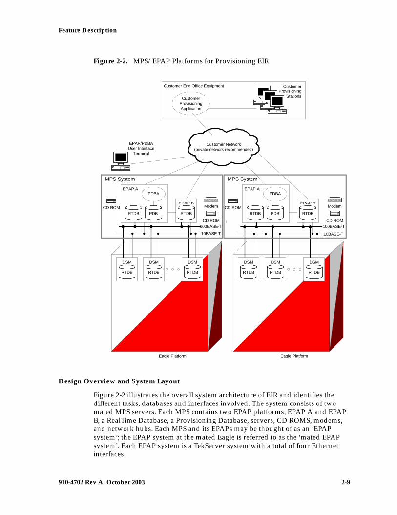
Figure 2-2. MPS/EPAP Platforms for Provisioning EIR .......................... 2-9
Figure 5-1. Obit Message for Abort of Card Loading ............................... 5-7
Figure 5-2. EIR Not Enabled, DSM Running in TSM Emulation ........... 5-8
Figure 5-3. EIR Enabled, Normal Operating Sequence .......................... 5-8
Figure 5-4. EIR Enabled, but DSM Memory Less Than 1 GB ................ 5-8
Figure 5-5. EIR Enabled, but DSM Not Connected to EPAP ................. 5-9
Figure 5-6. EIR Enabled, but DSM Memory Insufficient for Database .................................................................................................... 5-9
Figure 5-7. EIR Enabled, but Database Exceeds DSM Memory ............ 5-9
Figure 5-8. EIR Not Enabled at First, but then Activated on DSM ..... 5-10
Figure 5-9. EIR Activation Unsuccessful due to Insufficient Database ............................................................................ 5-10

910-4702 Rev A, October 2003 v
- Draft -
List of Tables
Table 2-1. Example Individual IMEI Table ................................................. 2-5
Table 2-2. Logic for IMEIs in Multiple Lists ............................................... 2-5
Table 2-3. Additional Files .......................................................................... 2-18
Table 3-1. Commands for Eagle EIR ............................................................ 3-2
Table 3-2. Individual IMEI List Determination Table ............................... 3-3
Table 3-3. chg-gsmopts Parameters - Class = DATABASE ...................... 3-5
Table 3-4. ent-srvsel Parameters - Class = DATABASE ........................... 3-6
Table 3-5. chg-srvsel Parameters - Class = DATABASE ........................... 3-6
Table 3-6. dlt-srvsel Parameters - Class = DATABASE ........................... 3-7
Table 3-7. rtrv-srvsel Parameters - Class = DATABASE ........................ 3-7
Table 4-1. DSM Card Locations .................................................................... 4-3
Table 4-2. NAIV/NAI Mapping ................................................................ 4-39
Table 4-3. NPV/NP Mapping ..................................................................... 4-40
Table 4-4. NAIV/NAI Mapping ................................................................ 4-45
Table 4-5. NPV/NP Mapping ..................................................................... 4-46
Table 4-6. NAIV/NAI Mapping ................................................................ 4-51
Table 4-7. NPV/NP Mapping ..................................................................... 4-51
Table 5-1. EIR UAMs ................................................................................... 5-11
Table 5-2. EIR UIMs ..................................................................................... 5-17
Table 5-3. Pegs for Per System EIR Measurements ................................. 5-22

List of Tables
vi 910-4702 Rev A, October 2003
- Draft -

910-4702 Rev A, October 2003 1-1
— Draft —
1
Introduction
Overview ...........................................................................................................1-1
Scope and Audience........................................................................................ 1–2
Manual Organization ...................................................................................... 1–2
Related Publications........................................................................................ 1–2
Documentation Packaging, Delivery, and Updates.................................... 1–6
Documentation Admonishments .................................................................. 1–7
Customer Assistance ....................................................................................... 1–7
Acronyms.......................................................................................................... 1–8
Overview
This manual provides details of the Equipment Identity Register (EIR) feature of the Eagle STP (Signal Transfer Point). This feature is intended to reduce the number of GSM mobile handset thefts by providing a mechanism to assist network operators in preventing stolen or disallowed handsets from accessing the network. This control will be done by using the International Mobile Equipment Identity (IMEI) provided during handset registration and comparing it against a set of lists provided by the network operator. There will be three lists Black, Gray and White. Mobile Stations (MS) on the white list will be allowed access to the network. MS's on the black list will be denied access to the network. MS's on the gray list will be allowed on the network, but may be tracked.
EIR is an optional feature on the Eagle STP, and can be turned on, but not off, via a Feature Access Key. Note that EIR requires the Global Title Translation (GTT) feature and the EIR Subsystem is mutually exclusive of the existing INP and LNP subsystems.

1-2 910-4702 Rev A, October 2003
Introduction
— Draft —
Scope and Audience
This manual is intended for anyone responsible for installing, maintaining, and using the EIR feature in the Eagle system. Users of this manual and the others in the Eagle family of documents must have a working knowledge of telecommunications and network installations.
Manual Organization
This document is organized into the following chapters:
• Chapter 1, “Introduction” , contains general information about the EIR documentation, the organization of this manual, and how to get technical assistance.
• Chapter 2, “Feature Description”, provides a functional description of the EIR feature, including network perspectives, assumptions and limitations, a database overview, DSM provisioning and reloading, EIR user interface, and an audit overview.
• Chapter 3, “Eagle EIR Commands”, describes the new or updated commands that support the EIR faeture. It provides some sample reports and explanations of appropriate comand usage.
• Chapter 4, “EIR Configuration”, describes how to activate the EIR feature.
• Chapter 5, “Maintenance and Measurements”, describes maintenance and measurements in detail, including EPAP status and alarms, hardware verification messages, TSM emulation mode, EIR system status reports and commands, code and application data loading, and alarms.
Related Publications
The Feature Manual – EIR refers to other manuals provided by the Eagle documentation set. The documentation set includes the following manuals:
• The Commands Manual contains procedures for logging into the system, logging out of the system, a general description of the terminals, printers, the disk drive used on the system, and a description of all the commands used in the system. The Commands Manual also contains the Commands Pocket Guide and the Commands Quick Reference.
• The Commands Pocket Guide is packaged with the Commands Manual and is also available as a separate item. This abridged version of the Commands Manual contains all the commands and parameters, and it shows the command-parameter syntax.
• The Commands Quick Reference is available as a separate item and it comes as a pocket-sized folded brochure. This brochure contains an alphabetical listing of the commands and parameters.

Introduction
910-4702 Rev A, October 2003 1-3
— Draft —
• The Commands Error Recovery Manual contains the procedures to resolve error message conditions generated by the commands in the Commands Manual. These error messages are presented in numerical order.
• The Database Administration Manual – Features contains procedural information required to configure the system to implement these features: X.25 Gateway, STP LAN, Database Transport Access, GSM MAP Screening, and Eagle Support for Integrated Sentinel.
• The Database Administration Manual – Features contains procedural information required to configure the system to implement these features: X.25 Gateway, STP LAN, Database Transport Access, GSM MAP Screening, and Eagle Support for Integrated Sentinel.
• The Database Administration Manual - Gateway Screening contains a description of the Gateway Screening (GWS) feature and the procedures necessary to configure the system to support this feature.
• The Database Administration Manual – Global Title Translation contains procedural information required to configure the system to implement these features: Global Title Translation, Enhanced Global Title Translation, Variable Length Global Title Translation, Interim Global Title Modification, and Intermediate GTT Load Sharing.
• The Database Administration Manual – LNP contains procedural information required to configure the system LNP and the database to implement the local number portability (LNP) feature.
• The Database Administration Manual – SEAS contains the procedures that can be performed from the Signaling Engineering and Administration Center (SEAC) or a Signaling Network Control Center (SNCC) to configure the EAGLE. These procedures contain a brief description of the procedure, a reference to the procedure in either the Database Administration Manual – SS7 or the Database Administration Manual – Features that contains more information on that procedure, and a flowchart showing the order that the tasks must be performed.
• The Database Administration Manual – IP7 Secure Gateway contains procedural information required to configure the system to implement the SS7-IP Gateway.
• The Database Administration Manual – SS7 contains procedural information required to configure the system to implement the SS7 protocol and the SS7-IP Gateway.
• The Database Administration Manual – System Management contains procedural information required to manage the Eagle’s database and GPLs, and to configure basic system requirements such as user names and passwords, system-wide security requirements, and terminal configurations.
• The Database Configuration Forms book contains forms to assist you in configuring your database. The forms are arranged alphabetically by command. Each form provides reference information on the command, its possible parameter values, and space for you to fill in the values that you use

1-4 910-4702 Rev A, October 2003
Introduction
— Draft —
to configure your database. The forms enable you to plan the input values prior to database administration sessions. The forms also provide a record of the intended data entered for a given database object. The forms may be duplicated as required.
• The LNP Feature Activation Guide contains procedural information required to configure the system for the LNP feature using telephone quantities from 24 million to 96 million telephone numbers.
• The FTP-Based Table Retrieve Application (FTRA) User Guide, provides the procedures for loading the FTRA software on a Windows PC or Unix workstation and the procedures for retrieving the Eagle database tables and for sending command files to the Eagle.
• The ELAP Administration Manual provides a definition of the user interface to the Eagle LNP Application Processor on the MPS/ELAP platform. The manual defines the methods for accessing the interface, menus, screens available to the user and describes their impact. It provides the syntax and semantics of user input and defines the output the user receives, including information and error messages.
• The EPAP Administration Manual describes how to administer to the Eagle Provisioning Application Processor on the MPS/EPAP platform. The manual defines the methods for accessing the user interface, menus, and screens available to the user and describes their impact. It provides the syntax and semantics of user input and defines the output the user receives, including messages, alarms, and status.
• The Feature Manual - EIR provides details of the feature providing network operators with the capability to prevent stolen or disallowed GSM mobile handsets from accessing the network. This manual gives the instructions and information on how to install, use, and maintain the EIR feature on the Multi-Purpose Server (MPS) platform of the Eagle System.
• The Feature Manual - G-Port provides details of the feature providing the capability for mobile subscribers to change the GSM subscription network within a portability cluster while retaining their original MSISDNs. This manual gives the instructions and information on how to install, use, and maintain the G-Port feature on the Multi-Purpose Server (MPS) platform of the Eagle System.
• The Feature Manual - G-Flex C7 Relay provides detail of the feature supporting the efficient management of Home Location Registers in various networks. This manual gives the instructions and information on how to install, use, and maintain the G-Flex feature on the Multi-Purpose Server (MPS) platform of the Eagle System.
• The Feature Manual - GR-376 provides information and instructions on how to implement and maintain the GR-376 feature.
• The Feature Manual - INP provides information and instructions on how to implement, utilize, and maintain the INAP-based Number Portability (INP) feature on the Multi-Purpose Server (MPS) platform of the Eagle System.

Introduction
910-4702 Rev A, October 2003 1-5
— Draft —
• The LNP Database Synchronization Manual describes how to keep the LNP databases at the LSMS and at the network element (the Eagle is a network element) synchronized through the use of resynchronization, audits and reconciles, and bulk loads. This manual is contained in both the LSMS documentation set and in the Eagle documentation set.
• The Maintenance Manual contains procedural information required for maintaining the Eagle STP system and the IP7 Secure Gateway system. The Maintenance Manual provides preventive and corrective maintenance procedures used in maintaining the different systems.
• The Maintenance Pocket Guide is packaged with the Maintenance Manual and is also available as a separate item. This abridged version of the Maintenance Manual contains all the corrective maintenance procedures used in maintaining the Eagle STP system.
• The Emergency Recovery Pocket Guide is packaged with the Maintenance Manual and is also available as a separate item. This abridged version of the Maintenance Manual contains the corrective maintenance procedures for the critical and major alarms generated on the Eagle STP system.
• The Eagle STP with TekServer IAS MPS Platform Software and Maintenance Manual describes the TekServer core platform features and the MPS customization features that make up the Multi-Purpose Server (MPS) platform software. This manual also describes how to perform preventive and corrective maintenance for the MPS.
• The Signaling Products Hardware Manual contains hardware descriptions and specifications of Tekelec’s Network Systems Division (NSD) products. These include the Eagle STP system, the IP7 Secure Gateway (SG) system, and OEM-based products which include the ASi 4000 Service Control Point (SCP), and the Integrated Sentinel with Extended Services Platform (ESP) subassembly.
The Signaling Products Hardware Manual provides an overview of each system and its subsystems, details of standard and optional hardware components in each system, and basic site engineering. Refer to this manual to obtain a basic understanding of each type of system and its related hardware, to locate detailed information about hardware components used in a particular release, and to help configure a site for use with the system hardware.
• The NSD Installation Manual contains cabling requirements, schematics, and procedures for installing the Eagle systems along with LEDs, Connectors, Cables, and Power Cords to Peripherals. Refer to this manual to install components or the complete systems.
• The Signaling Products Integrated Applications Installation Manual provides the installation information on Frame Floors and Shelves for Integrated Applications Products such as MPS EPAP 4.0, ASi 4000 SCP, and VXi Media Gateway Controller, Integrated and Non-Integrated Sentinel, LEDs, Connectors, Cables, and Power Cords to Peripherals. Refer to this manual to install components or the complete systems.

1-6 910-4702 Rev A, October 2003
Introduction
— Draft —
• The TekServer Services Platform Hardware Manual provides general specifications and a description of the TekServer. This manual also includes site preparation, environmental and other requirements, procedures to physically install the TekServer, and troubleshooting and repair of Field Replacable Units (FRUs).
• The Provisioning Database Interface Manual defines the programming interface that populates the Provisioning Database (PDB) for the Eagle features supported on the MPS/EPAP platform. The manual defines the provisioning messages, usage rules, and informational and error messages of the interface. The customer uses the PDBI interface information to write his own client application to communicate with the MPS/EPAP platform.
• The Release Documentation contains the following documents for a specific release of the system:
Release Notice - Describes the changes made to the system for the specified release. Lists the Generic Program Loads (GPLs) for the specified release. Note: The most current version of this document is published on the Tekelec Secure website.
Feature Notice - Describes the features contained in the specified release. Also provides the hardware baseline for the specified release, describes the customer documentation set, provides information about customer training, and explains how to access the Customer Service website.
Technical Bulletins - Contains updates to methods or procedures used to maintain the system.
System Overview - Provides high-level information on SS7, the IP7 Secure Gateway, system architecture, LNP, and EOAP.
Master Glossary - Contains an alphabetical listing of terms, acronyms, and abbreviations relevant to the system.
Cross-Reference Index - Lists all first-level headings used throughout the documentation set.
• Previously Released Features - Contains descriptions of previously released system features.
Documentation Packaging, Delivery, and Updates
Customer documentation is provided with each system in accordance with the contract agreements. It is updated whenever significant changes that affect system operation or configuration are made. Updates may be issued as an addendum, or a reissue of the affected documentation.
The document part number appears on the title page along with the current revision of the document, the date of publication, and the software release that the document covers. The bottom of each page contains the document part number and date of publication.

Introduction
910-4702 Rev A, October 2003 1-7
— Draft —
Two types of releases are major software releases and maintenance releases. Maintenance releases are issued as addenda with a title page and change bars. On changed pages, the date and document part number are changed; on unchanged pages that accompany the changed pages, the date and document part number are unchanged.
When the software release has a minimum affect on documentation, an addendum is provided. The addendum contains an instruction page, a new title page, a change history page, and replacement chapters with the date of publication, the document part number, and change bars.
If a new release has a major impact on documentation, such as a new feature, the entire documentation set is reissued with a new part number and a new release number.
Documentation Admonishments
Admonishments are icons and text throughout this manual that alert the reader toassure personal safety, to minimize possible service interruptions, and to warn of the potential for equipment damage. This manual has three admonishments, listed in descending order of priority.
DANGER: This icon and text indicate the possibility of personal injury.
WARNING: This icon and text indicate the possibility of equipment damage.
CAUTION: This icon and text indicate the possibility of service interruption.
Customer Assistance
The Tekelec Technical Services department offers a point of contact through which customers can receive support for problems that may be encountered during the use of Tekelec’s products. The Tekelec Technical Services department is staffed with highly trained engineers to provide solutions to your technical questions and issues seven days a week, twenty-four hours a day. A variety of service programs are available through the Tekelec Technical Services department to maximize the performance of Tekelec products that meet and exceed customer’s needs.

1-8 910-4702 Rev A, October 2003
Introduction
— Draft —
To receive technical assistance, call the Tekelec Technical Services department at one of these locations:
• Tekelec, UK
Phone(within the UK): 07071 232453
(outside the UK): +44 7071 232453 or +44 1784 437067
• Tekelec, USA
Phone(within continental US):(800) 432-8919
(outside continental US): +1 919-460-2150
Or, you can request assistance via electronic mail at [email protected].
Acronyms
ADL Application Data Loader
AuC Authentication Center
CC E.164 Country Code
CCRNDN Country Code + Routing Number + National Directory Number
CdPA Called Party Address
CgPA Calling Party Address
CPC Capability Point Code
CRP Circular Route Prevention
DCB Device Control Block
DCM Data Communications Module
DSM Database Services Module
EIR Equipment Identity Register
EPAP Eagle Provisioning Application Processor
ES Encoding Scheme
ETSI European Telecommunications Standards Institution
FTP File Transport Protocol
FTR File Transfer Region
GDB G-Flex/G-Port/INP Database
GFDB G-Flex Database
G-Flex GSM Flexible Numbering
GMSC Gateway Mobile Switching Center
G-Port GSM Mobile Number Portability

Introduction
910-4702 Rev A, October 2003 1-9
— Draft —
GPL Generic Program Load
GSM Global System for Mobile communications
GTA Global Title Address
GTAI Global Title Address Information
GTI Global Title Indicator
GTT Global Title Translation
HLR Home Location Register
HomeRN Home Network Routing Number Prefix
IAM Initial Address Message
IMEI International Mobile Equipment Identity
IMSI International Mobile Station Identifier
IN Intelligent Network
INAP Intelligent Network Application Protocol
INP INAP-Based Number Portability
IP Internet Protocol
IS-41 International Standard 41, same as ANSI-41
ISDN Integrated Services Digital Network
ITU International Telecommunications Union
LIM Link Interface Module
LNP Local Number Portability
LSS Local Subsystem
MAP (1) Mobile Application Part (2) Mated APplication
MAS Maintenance and Administration Subsystem
MCAP MAS Communication Application Processor Card
MEA Mismatch of Equipment and Attributes
MDN Mobile Directory Number
MGT Mobile Global Title
MIN Mobile Identification Number
MMI Man-Machine Interface
MNP Mobile Number Portability
MPS Multi-Purpose Server (Multi-Platform Server)
MS Mobile Station

1-10 910-4702 Rev A, October 2003
Introduction
— Draft —
MSRN Mobile Station Roaming Number
MSC Mobile Switching Center
MSISDN Mobile Station international ISDN number
MSU Message Signaling Unit
MTP Message Transfer Part
NC E.214 Network Code
NDC E.164 National Destination Code
NP (1) Number Portability(2) Numbering Plan
NPA Numbering Plan Area
NPDB Number Portability Database
NPV Numbering Plan Value
NSD Network Systems Division, Tekelec
OAI Object Access Interface
OAM Operation Administration & Maintenance
OAP Operations Support System/ Application Processor
OPS Operator Provisioning System
PDB Provisioning Database
PDBA Provisioning Database Application
PDBI Provisioning Database Interface
PFS Product Functional Specification
PLMN Public Land Mobile Network
PMTC Peripheral Maintenance Control
RMTP Reliable Multicast Transport Protocol
RNIDN Routing Number prefix + International dialed / Directory Number
RNNDN Routing Number prefix + National dialed / Directory Number
RNSDN Routing Number prefix + Subscriber dialed / Directory Number
RTDB Real-Time Database
SCCP Signaling Connection Control Part
SCMG SCCP Management
SCP Service Control Point
SDS System Debug Services
SIM Subscriber Identity Module

Introduction
910-4702 Rev A, October 2003 1-11
— Draft —
SMS (1) Service Management System, or(2) Short Message Service
SNP Service Numbering Plan
SP Signaling Point
SPC Secondary Point Code
SRF Signaling Relay Function
SRI Send Routing Information
SS7 Signaling System 7
SSH Secure Shell
SSN Subsystem Number
SSP Service Switching Point
STP Signal Transfer Point
TCAP Transaction Capabilities Application Part
TCP Transmission Control Protocol
TFA Transfer Allowed
TFP Transfer Prohibited
TSM Translation Service Module
TT Translation Type
UAM Unsolicited Alarm Message
UDP User Datagram Protocol
UDT Unit Data Transfer
UDTS Unit Data Transfer Service
UIM Unsolicited Information Message
UPU User Part Unavailable
VLR Visitor Location Register
VMSC Voice Mail Service Center
VSCCP VxWorks Signaling Connection Control Part

1-12 910-4702 Rev A, October 2003
Introduction
— Draft —

910-4702 Rev A, October 2003 2-1
— Draft —
2
Feature Description
Introduction...................................................................................................... 2–1
EIR Considerations ....................................................................................2-3
EIR Call Flows...................................................................................................2-3
EIR List Determination..............................................................................2-7
MPS/EPAP Platform....................................................................................... 2–8
Design Overview and System Layout ....................................................2-9
Functional Overview .............................................................................. 2–10
EPAP/PDBA Overview ......................................................................... 2–11
EIR Protocol .................................................................................................... 2–13
Messages for Local Subsystems ............................................................ 2–14
MTP and SCCP Management to Support EIR .................................... 2–14
Check_IMEI Message Handling ............................................................2-15
EIR List Log File..............................................................................................2-16
EIR Log File Serviceability......................................................................2-16
EIR List Log Format.................................................................................2-17
Introduction
A handset theft problem exists in GSM networks in many countries. A person obtains a legitimate subscription to a network, and then obtains a legitimate IMSI, MSISDN, and SIM card. The person initially buys an inexpensive handset and then steals a better handset from another subscriber. Once the handset is stolen, the thief replaces the SIM card with his/her own legitimate SIM card. Since the SIM card and subscriber information contained therein (IMSI, MSISDN) are

2-2 910-4702 Rev A, October 2003
Feature Description
— Draft —
legitimate, the phone will operate and the network operator has no way to determine that the subscriber is using a stolen handset. In addition to individual handset theft, organized groups have begun stealing entire shipments of mobile handsets from warehouses, and then selling these handsets on the black market.
This feature is intended to reduce the number of GSM mobile handset thefts by providing a mechanism that allows network operators to prevent stolen or disallowed handsets from accessing the network. This control is done by using the International Mobile Equipment Identity (IMEI) provided during handset registration and comparing it against a set of lists provided by the network operator. There are three lists; Black, Gray, and White. Mobile Stations (MS) on the white list are allowed access to the network. MS’s on the black list are denied access to the network. MS’s on the gray list are allowed on the network, but may be tracked.
The Equipment Identity Register (EIR) is a network entity used in GSM networks that stores lists of International Mobile Equipment Identity (IMEI) numbers, which correspond to physical handsets (not subscribers). The IMEI is used to identify the actual handset, and is not dependent upon the International Mobile Subscriber Identity (IMSI), Mobile Station International ISDN Number (MSISDN) or the Subscriber Identity Module (SIM). The IMSI, MSISDN, and SIM are all subscriber-specific, and move with the subscriber when he/she buys a new handset. The IMEI is handset specific.
The EIR database stores white, grey, and black lists of IMEI numbers. When a subscriber roams to a new MSC/VLR location, the handset attempts registration with the MSC/VLR. Before the MSC registers the subscriber with the VLR, it may sends a query to the EIR. The EIR returns a response indicating whether the IMEI is allowed, disallowed, or invalid. If the IMEI is allowed, the MSC completes registration, otherwise, registration is rejected.
The EIR may also contain associations between individual IMEIs and IMSIs. This would provide a further level of screening by directly associating a particular IMEI with a particular IMSI. This association is used in the following way:
• If an IMEI is found on a black list, an additional check of the IMSI could then be made.
• If the IMSI from the handset matches the IMSI provisioned with the IMEI, this would override the black list condition, and allow registration to continue. This could be used to protect against mistaken black list entries in the database, or to prevent unauthorized "handset sharing". Obviously, this association could be used in other ways.
Use of the EIR can prevent the use of stolen handsets since the network operator can enter the IMEI of these handsets into a 'blacklist' and prevent them from being registered on the network, thus making them useless.

Feature Description
910-4702 Rev A, October 2003 2-3
— Draft —
EIR Considerations
1. GTT must be ON before the EIR feature can be enabled.
2. The EIR feature is mutually exclusive with INP.
3. The EIR feature is mutually exclusive with LNP.
4. The EIR feature cannot be enabled if any ASMs or TSMs are in the system.
EIR Call Flows
When a handset roams into a new MSC/VLR area, it attempts a registration procedure with the VLR. In a network without the EIR function, this procedure results in the VLR sending a location update message to the HLR, providing the HLR with the current MSC location of the Mobile Station (MS)/handset. Once the EIR is deployed, this registration procedure is interrupted in order to validate the IMEI of the MS/handset attempting to register before completing the registration procedure and updating the HLR.
In the EIR network, the MSC/VLR sends a MAP_CHECK_IMEI message to the EIR prior to sending a location update to the HLR. This message contains, at a minimum, the IMEI of the MS attempting registration. It may also contain the IMSI of the subscriber whose SIM card is currently being used in the MS/handset. Upon receipt of this message, the EIR searches the white, grey, and black lists for a match on the IMEI. The EIR then returns a response to the MSC. Depending upon the result of the search, the response contains either the Equipment Status of the MS/handset (whether the IMEI for the MS/handset is allowed or not based on its status in the white, grey, or black lists), or a User Error (invalid or unknown IMEI). The MSC then either continues the registration procedure (if the IMEI is allowed), or rejects it (if the IMEI is disallowed, invalid, or unknown).
If the IMSI is also included in the message, the EIR attempts to match this IMSI to one provisioned with the IMEI prior to sending a response to the MSC. A match on IMSI in this case overrides any black list condition found based on the IMEI match alone, and causes a response of MS allowed.
Refer to Figure 2-1 and the following text for Eagle EIR call flow information.

2-4 910-4702 Rev A, October 2003
Feature Description
— Draft —
Figure 2-1. EIR Call Flow
1. The MS/handset roams into new serving MSC/VLR area, and begins registration procedure with Base Station (BS).
2. The BS begins the registration procedure with MSC/VLR
3. Before allowing the MS/handset to register on the network, and prior to updating the HLR with the new MSC information, the MSC launches a MAP_CHECK_IMEI message to the EAGLE EIR. This message is either MTP-routed directly to the point code of the EAGLE and the EIR subsystem (SSN = "EIR"), or is GT-routed and the EAGLE GT-translates the message to its own point code and local EIR SSN = "EIR"
4. The EAGLE EIR retrieves the IMEI and/or IMSI from the message and searches the EIR tables for a match. Refer to Tables 2-5. This search may result in the IMEI being on the white, grey, and/or black lists, or it may result in an invalid or unknown IMEI (no match). It may also result in an invalid IMSI-IMEI combination. Based on the results of the search, the EAGLE EIR returns a MAP_CHECK_IMEI_ack containing either the Equipment Status (IMEI on allowed or not allowed), or a User Error (invalid or unknown IMEI).
5. (Not shown). The MSC either rejects or completes the registration attempt, depending on the information returned by the EIR.
The EIR tables contain lists of IMEIs, and an indication as to the list they are located. There are two types of tables - an Individual IMEI table (Table 2-1) and a Range IMEI table. The Individual IMEI table is searched first. The IMEI entries in this table may also contain an association to an IMSI. If no match is found in the individual table, the range IMEI table is searched.
MSC/MSC/VLRVLR
HLRHLR
EAGLE EAGLE EIREIR
BS
MS
12
3 (MAP_CHECK_IMEI)MTP DPC = EAGLE EIR PCMTP OPC = MSCSCCP CdPA DPC = EAGLE EIR PCSCCP CdPA SSN = 9SCCP CdPA RI = 1 (route on SSN)
4 (MAP_CHECK_IMEI_ack)
MSC/MSC/VLRVLR
HLRHLR
EAGLE EAGLE EIREIR
BS
MS
12
3 (MAP_CHECK_IMEI)MTP DPC = EAGLE EIR PCMTP OPC = MSCSCCP CdPA DPC = EAGLE EIR PCSCCP CdPA SSN = 9SCCP CdPA RI = 1 (route on SSN)
4 (MAP_CHECK_IMEI_ack)

Feature Description
910-4702 Rev A, October 2003 2-5
— Draft —
The EIR can support up to 56 million individual IMEIs. A total of up to 50,000 IMEI ranges are supported.The total Eagle database capacity for all advanced database service features, including EIR, G-Flex, and G-Port is 56 million individual numbers. If entries exist for these other services (MSISDNs for G-Port or IMSIs for G-Flex), reduces the available capacity for IMEIs. Also, if IMSIs are entered for the "IMSI Check" option of the EIR, those entries will also reduce the available IMEI capacity.
As shown in Table 2-1, it is possible for a given IMEI to be on multiple lists (e.g. on the white list, and also on the grey and/or black list). The logic described by Table 2-2 is used to determine which answer to return in the CHECK_IMEI response, determined by which list(s) the IMEI is on. Table 2-2 also shows three possible EIR Response Types. The EIR Response Type is a system-wide EIR option, that is configured by the user. The combination of the setting of the EIR Response Type, in which list(s) the IMEI is located, and the optional IMSI check, determines the response that is returned to the querying MSC.
Example Scenerios
Table 2-1. Example Individual IMEI Table
IMEI IMSI (optional) White List Grey List Black List
12345678901234 495867256894125 No No Yes
234567890123456 No Yes No
49876523576823 No Yes Yes
68495868392048 495867565874236 Yes Yes No
29385572695759 Yes Yes Yes
Table 2-2. Logic for IMEIs in Multiple Lists
Presence in List EIR Response Type
White Grey Black Type 1 Type 2 Type 3
X in white list in white list in white list
X X in grey list in grey list in grey list
X X X in black list in black list in black list
X X in black list in black list in black list
X in grey list in grey list unknown
X X in black list in black list unknown
X in black list in black list unknown
in white list unknown unknown

2-6 910-4702 Rev A, October 2003
Feature Description
— Draft —
Example 1
1. A CHECK_IMEI is received with IMEI = 49876523576823, no IMSI in message.
2. A match is found in the Individual table (Table 2-1, entry 3), indicating the IMEI is on the grey and black lists.The EIR Response Type is set to Type 3, and an IMSI is not present.
3. Per the logic in Table 2-2, the required response is Unknown.
4. The EIR formulates a CHECK_IMEI error response with Error = 7 unknownEquipment.
Example 2
Same as Example 1, but the setting of the EIR Response Type is re-provisioned by the operator to Type 2.
1. A CHECK_IMEI is received with IMEI = 49876523576823, no IMSI in message.
2. A match is found in the Individual table (Table 2-1, entry 3), indicating the IMEI is on the grey and black lists.The EIR Response Type is set to Type 2, and an IMSI is not present.
3. Per the logic in Table 2-2, the required response is Black Listed.
4. The EIR formulates a CHECK_IMEI response with Equipment Status = 1 blackListed.
Example 3
1. A CHECK_IMEI is received with IMEI = 12345678901234, and IMSI = 495867256894125.
2. A match is found in the Individual table (Table 2-1, entry 1), indicating the IMEI is on the black list.
3. The EIR Response Type is set to Type 1.
4. Per the logic in Table 2-2, the normally required response would be Black Listed, however; since an IMSI is present in the message, and the IMEI is on the black list, the IMSI is compared to the IMSI entry in the database for this IMEI.
5. In this case, the IMSI in the DB matches the IMSI in the query, thus the black list condition is cancelled.
6. The EIR formulates a CHECK_IMEI response with Equipment Status = 0 whiteListed.
Example 4
1. A CHECK_IMEI is received with IMEI = 12345678901234, and IMSI = 495867256894125.
2. A match is found in the Individual table (Table 2-1, entry 1), indicating the IMEI is on the black list.
3. The EIR Response Type is set to Type 1.

Feature Description
910-4702 Rev A, October 2003 2-7
— Draft —
4. Per the logic in Table 2-2, the normally required response would be Black Listed, however; since an IMSI is present in the message, and the IMEI is on the black list, the IMSI is compared to the IMSI entry in the database for this IMEI.
5. In this case, the IMSI in the DB does not match the IMSI in the query, thus the black list condition is maintained.
6. The EIR formulates a CHECK_IMEI response with Equipment Status = 1 blackListed.
EIR List Determination
If the global response option is set (with the eirgrsp parameter of the chg-gsmopts command) to a value other than off, the IMEI is treated as being on the list indicated by the global response option, regardless of the actual status of the IMEI. No list logic processing is performed on the IMEI.
If the global response option is set to off, the IMEI table is searched first. If no match is found in the IMEI table, the IMEI Block table is searched next. If the IMEI is found on only the White List after either table search, the list logic processing is complete, and the White List status of the IMEI is sent to the MSC.
Black List Processing
If the IMEI is found on the Black List after either table search, list logic processing continues based on the EIR response type, set by the eirrsptype parameter of the chg-gsmopts command. If the EIR response type is type 3, and the IMEI is not also found on the White List, the status of the IMEI is unknown.
If the IMEI is found on the White List also, or if the EIR response type is either type 1 or 2, the value of the IMSI check option, set with the eirimsichk parameter of the chg-gsmopts command is checked. If the IMSI check option is on, and the IMSI is present in the message, the IMSI table is searched. If there is a match for the IMSI, the status of the IMEI is determined to be “White with Override.” If there is no match for the IMSI, the status of the IMEI is determined to be “Black with IMSI Match Failed.” If the value of the IMSI check option is off, the status of the IMEI is determined to be on the Black List.
Gray List Processing
If the IMEI is found on the Gray List after either table search, list logic processing continues based on the EIR response type, set by the eirrsptype parameter of the chg-gsmopts command. If the EIR response type is type 3, and the IMEI is not also found on the White List, the status of the IMEI is unknown.
If the IMEI is found on the White List also, or if the EIR response type is either type 1 or 2, the status of the IMEI is determined to be on the Gray List.

2-8 910-4702 Rev A, October 2003
Feature Description
— Draft —
MPS/EPAP Platform
Tekelec provides the MPS (Multi-Purpose Server) platform as a subsystem of the Eagle. The MPS provides support for multiple features, which currently are the INP, G-Flex, G-Port, and EIR features.
The MPS is composed of hardware and software components that interact to create a secure and reliable platform. (For details about the MPS hardware, refer to the MPS Hardware Manual.) The MPS provides the means of interfacing the customer provisioning application with the Eagle. It connects the customer with the Eagle and accepts the customer number portability data, while accommodating numbers of varying lengths.
The Eagle Provisioning Application Processor (EPAP) is the software that runs on the MPS hardware platform. It collects and organizes customer provisoning data, and forwards it to the Eagle DSM cards. Figure 2-2 shows the overall system architecture, providing a graphic overview of MPS/EPAP platform from customer provisioning through the MPS subsystem to the Eagle DSM databases.
Feature Description
910-4702 Rev A, October 2003 2-9
— Draft —
Figure 2-2. MPS/EPAP Platforms for Provisioning EIR
Design Overview and System Layout
Figure 2-2 illustrates the overall system architecture of EIR and identifies the different tasks, databases and interfaces involved. The system consists of two mated MPS servers. Each MPS contains two EPAP platforms, EPAP A and EPAP B, a RealTime Database, a Provisioning Database, servers, CD ROMS, modems, and network hubs. Each MPS and its EPAPs may be thought of as an ‘EPAP system’; the EPAP system at the mated Eagle is referred to as the ‘mated EPAP system’. Each EPAP system is a TekServer system with a total of four Ethernet interfaces.
Eagle Platform
DSM
RTDB
DSM
RTDB
DSM
RTDB
EPAP B
RTDB
Eagle Platform
DSM
RTDB
DSM
RTDB
DSM
RTDB
100BASE-T
10BASE-T
Customer End Office Equipment
CustomerProvisioningApplication
CD ROM
EPAP A
PDBRTDB
PDBA
Backupdevice
EPAP B
RTDBCD ROM
EPAP A
PDBRTDB
PDBA
Backupdevice 100BASE-T
10BASE-T
Customer Network(private network recommended)
EPAP/PDBAUser Interface
Terminal
CD ROM
Modem
Backupdevice
CD ROM
Modem
Backupdevice
CustomerProvisioning
Stations
MPS System MPS System

2-10 910-4702 Rev A, October 2003
Feature Description
— Draft —
On the Eagle platform side, a set of DSMs, which hold the EIR database, is part of the STP. Two high-speed Ethernet links connect the DSMs and the EPAPs. One of the links is a 100BASE-T Ethernet bus, and the other is a 10BASE-T Ethernet bus.
The EIR database is provisioned and maintained through the EPAPs. EPAP A and EPAP B act as the active EPAP and the standby EPAP. One link serves as the active link, and the other as the standby link. At any given time, there is only one active EPAP and one active link. The database is provisioned through the active link by the active EPAP; the other EPAP provides redundancy.
In case of failure of the active EPAP, the standby EPAP takes over the role of active EPAP and continues to provision the EIR database. In the case where the active link fails, the active EPAP switches to the standby link to continue provisioning the DSMs. The two Ethernet links are part of the DSM network.
Another 100BASE-T Ethernet link exists between the EPAPs; that link is called the EPAP sync network.
Major modules on the EPAP are the:
• DSM provisioning module
• Maintenance module
• RTDB module
• PDB module
The DSM provisioning module is responsible for updating EIR databases on the Eagle DSM cards using the RMTP multicast. The maintenance module is responsible for the proper functioning of the EPAP platform. The PDB module is responsible for preparing and maintaining the Real Time Database, which is the “golden copy” of the EIR database. The PDB module can run on one of the EPAPs of either of the mated Eagles.
Functional Overview
The main function of the MPS/EPAP platform is to provision the EIR data from the customer network to the DSM cards on the STP. EIR database records are continuously updated from the customer network to the PDB. The PDB module communicates with the maintenance module and the RTDB task over a TCP/IP socket to provision the DSM cards on the Eagle. The maintenance module is responsible for the overall stability and performance of the system.
It is possible for the DSM database to get out-of-sync due to missed provisioning or card rebooting. Therefore, the RTDB contains a coherent, current copy of the DSM database. The EPAP-DSM provisioning task sends database information out on the provisioning link. The DSM cards act as the receivers and are reprovisioned.

Feature Description
910-4702 Rev A, October 2003 2-11
— Draft —
EPAP/PDBA Overview
The Eagle Provisioning Application Processor (EPAP) platform and the Provisioning Database Application (PDBA) coupled with the Provisioning Database Interface (PDBI) facilitate the database required for the EIR feature. It performs the following two basic functions in support of the EIR feature:
• Accept and store EIR data provisioned by the customer
• Update and reload EIR databases on the DSM cards
The PDBA operates on the master EIR provisioning database (PDB). The EPAP and PDBA are both installed on the MPS hardware platform.
The EPAP platform maintains an exact copy of the real-time database (RTDB) required by the Eagle DSM cards, provisions the Eagle DSM cards, and maintains redundant copies of both databases on mated EPAP hardware. The EPAP platform is a mated pair of processors (the upper processor, called EPAP A, and the lower processor, EPAP B) contained in one frame.
During normal operation, information flows through the EPAP/PDBA software with no intervention. EIR data is generated at one or more operations centers and is delivered to the PDBA through a TCP socket interface (PDBI). The PDBA software stores and replicates data on EPAP A on the mated EPAP system. The data is then transmitted across a private network to the DSM cards located in the Eagle frame by the EPAPs.
The primary interface to the PDBA consists of machine-to-machine messages. The interface is defined by Tekelec and is available in the Provisioning Database Interface Manual. Use that manual to update or create provisioning software compatible with the EPAP socket interface.
A direct user interface is provided on each EPAP to allow configuration, maintenance, debugging, and platform operations. A direct user interface is also provided by the PDBA for configuration and database maintenance.
The MPS/EPAP is an open systems platform and easily accommodates the high provisioning rates that EIR requires. Implementing the persistent database and provisioning as an open systems platform, compared to the traditional OAM platform, provides these benefits:
• Variety of hardware components and vendors
• Availability of third party communication and database tools
• Standard communication protocols
• Availability of personnel with related experience
Each EPAP server maintains a copy of the real-time database in order to provision the Eagle DSM cards. The EPAP server must comply with the hardware requirements in the MPS Hardware Manual. Figure 2-2 illustrates the EPAP architecture contained in the MPS subsystem.

2-12 910-4702 Rev A, October 2003
Feature Description
— Draft —
Each EPAP has a dedicated CD ROM drive. One EPAP per Eagle platform has a modem capable of supporting remote diagnostics, remote configuration, and remote maintenance; these remote operations are performed through EPAP login sessions. These sessions are accessible across the customer network (that is, the ssh) as well as through direct terminal connection to the EPAP via an RS232 connection. Refer to the MPS Hardware Manual for details about the hardware devices and network connections.
EPAP (Eagle Provisioning Application Processor)
As shown in Figure 2-2, a MPS/EPAP platform contains two EPAP servers to provide EIR service. At any given time, only one EPAP actively communicates with the DSMs. The other EPAP is in standby mode.
The primary purpose of the EPAPs is to maintain the provisioning database (PDB) and to download copies of the RTDB to the DSM cards. The EPAP receives EIR data from the customer network through the PDBI, the external source of EIR provisioning information. The PDBI continually updates the active EPAP’s PDB. Once an update is applied to the active PDB, it is sent to the RTDBs on the active and standby EPAPs.
Each EPAP maintains a copy of the RTDB. When a DSM needs a copy of the RTDB, the EPAP downloads the file to the DSM for its own resident copy of the RTDB database.
The EPAP maintains a file of database updates to be sent to the DSMs. This file contains the changes necessary to keep the DSM files current relative to the RTDB database.
DSM (Database Services Module)
The EIR feature can provision from 1 to 25 DSM cards.
Multiple DSMs provide a means of load balancing in high-traffic situations. The DSM database is in a format that facilitates rapid lookups. Each DSM contains an identical database. Furthermore, all DSM EIR databases are identical to the RTDB maintained by the EPAPs.
However, the various databases may not be identical at all times for several reasons. First of all, when a DSM card is initialized, it downloads the current copy of the database from the EPAP. While that card is being downloaded, it cannot provide VSCCP services. Another condition that can result in databases being out-of-sync occurs when the EPAP receives updates from its provisioning source, but it has not yet sent them down to the DSM cards. Updates are applied to the provisioning database as they are received.

Feature Description
910-4702 Rev A, October 2003 2-13
— Draft —
Two possible scenarios contribute to a condition where a DSM may not have enough memory to hold the entire database. In the first case, the database is downloaded successfully to the DSM, but subsequent updates eventually increase the size of the database beyond the capacity of the DSM memory. In this situation, it is desirable to continue processing INP transactions, even though the database may not be as up-to-date as it could be.
The other case occurs when a DSM card is booted. If it is determined then that the card does not have enough memory for the entire database, the database is not loaded on that card. Each DSM is responsible for recognizing and reporting its out-of-memory conditions by means of alarms.
Incremental Downloading
Once a download is in progress, it is possible for another DSM to determine that it also needs to download the file. The new DSM can “jump in” and join the download in progress and begin its download with whatever record is currently being sent. When the last record in the file has been sent, the EPAP restarts the download from the beginning. The EPAP then sends the records that the new DSM needs to complete its database.
EPAP Status and Error Reporting via Maintenance Blocks
The EPAPs forward all status and error messages to the DSMs in maintenance blocks. Maintenance blocks are asynchronously sent whenever the EPAP has something to report. The maintenance blocks eventually update EPAP DCBs located on the Eagle.
EIR Protocol
The Eagle supports the EIR capability point code type and an additional local subsystem that is entered into the MAP table. Like other entries in the MAP table, this subsystem has a mate subsystem, and a concerned point code group assigned to it. This subsystem is administered using MAP commands (ent-map, chg-map, dlt-map). Both ITU-I and ITU-N point codes are supported in the MAP commands. The EIR subsystem cannot be set to Load Shared mode (as end nodes do not perform load sharing), but is set to Dominant or Solitary mode. The EIR Subsystem has the restriction that only one local subsystem and capability point code type can be active at any instant.

2-14 910-4702 Rev A, October 2003
Feature Description
— Draft —
Messages for Local Subsystems
The message arrives on the EIR subsystem on rt-on-ssn or rt-on-gt. If the message arrives rt-on-ssn, it must contain either the Eagle’s true point code or the EIR capability point code in the DPC field of the message, and Eagle’s EIR Subsystem number in the Called Party Subsystem field of the message. If EIR queries has the Eagle’s capability point code for the DPC, then the Eagle processes the message, but is not able to divert this message in the event of subsystem failure.
If a message arrives on the EIR subsystem on rt-on-gt, it should also contain a service selector that translates to an EIR Subsystem. These messages also contain one of Eagle’s capability point codes in the DPC field. The Eagle also processes the message if it has the Eagle’s true point code for the DPC, but it is not able to divert these messages in the event of subsystem failure.
If the local EIR subsystem is offline and the mated subsystem is available, the routing indicator is used to determine whether to reroute:
• If the message arrived route-on-ssn, the message is not rerouted to the mate. In this case, Eagle is acting as an end node, and end nodes do not reroute. If the return on error option is set, the Eagle generates a UDTS, otherwise it will discard the message
• If the message arrived on route-on-gt, the message is rerouted to the mated subsystem. In this case, Eagle is acting as both STP and SCP, and STPs do reroute messages.
MTP and SCCP Management to Support EIR
If the EIR is offline, the Eagle sends SSPs that causes the rt-on-ssn message to be diverted to the mate subsystem.These do not cause the rt-on-gt messages to be diverted. In order to make other nodes divert rt-on-gt traffic to the mate, the Eagle will send response method TFPs to the OPC of the message, when messages arrive rt-on-gt for one of the EIR Capability Point Codes and the result of translation is the Eagle's EIR Subsystem. This TFP should cause the OPC to divert traffic to the mate. If a message arrives rt-on-gt for the Eagle's True Point Code, the Eagle will not generate a TFP. Therefore, nodes that send rt-on-gt traffic to the Eagle should use one of EIR Capability Point Codes, not the Eagle's True Point Code.
If the Eagle receives an RSP (Route Set Test Message - Prohibited) for a EIR Capability Point Code, and the EIR subsystem is offline, the Eagle does not reply. If the Eagle receives an RSR (Route Set Test Message - Restricted) for EIR Capability Point Code, and the EIR subsystem is offline, the Eagle replies with a TFP concerning the Capability Point Code. When EIR is online, RSRT replies to both RSRs and RSPs for EIR Capability Point Code with a TFA.

Feature Description
910-4702 Rev A, October 2003 2-15
— Draft —
Check_IMEI Message Handling
When the CHECK_IMEI message is received by protocol, the, IMSI (if active) and SVN are parsed from the MSU. Because different vendors place the IMSI information in different locations within the message, the decoder searches for the IMSI in multiple locations.
Once the required data is parsed, a call is made to the RTDB to determine the response type for the IMEI/IMSI combination.
The appropriate response messageis sent to the originating MSC.
Encoding Errors
When a Response is generated, it is sent based on the CgPA information in the incoming message. However, some conditions may prevent the EAGLE from generating the response. Most of the errors involve GTT on the CgPA; if the incoming data is rt-on-ss, the number of potential errors is much smaller.
Whenever an encoding error is detected, the Response message is discarded.
Data Collection
All messages received peg the following measurement: Total Messages (confirmed to have MAP Operation of CheckIMEI). At the end of processing, a single measurement is pegged:
• black listed
• black listed, but allowed due to IMSI match
• black listed, IMSI did not match
• white listed
• gray listed
• unknown
• no match (based on Response Type, this could be White or Unknown)
This following information is reported to ATH for rept-Stat-sccp.
• Counters
• Success
• Failures
• Processing Time
• Total Messages
At the end of the EIR service, Processing Time is updated with the elapsed time for this MSU. Total Messages is incremented, as is either success or failure. Warnings and Fall-thrus are not possible for EIR.
SCRC message counting is updated for SERVICE_MSG type.

2-16 910-4702 Rev A, October 2003
Feature Description
— Draft —
EIR List Log File
The EIR feature allows for detection and logging of subscribers using handsets that have been black-listed or grey-listed by a service provider. These messages are generated by the Eagle platform and forwarded to the MPS platform for later retrieval. Messages may be forwarded from any of the provisioned DSM cards. Messages will be received and logged independently by both MPS servers.
The files are located in the /var/TKLC/epap/free filesystem and is named as follows: pdbAutoExport_hostname.csv
Where:
hostname = the hostname of the MPS server that recorded the log
Each entry in the EIR log file contains information about the caller and handset, a timestamp, documenting the time the server received the log entry, and a unique identifier used for comparison with the mate server. Refer to the EIR List Log Format section for more information about the format of the file and the fields within the file.
The log file is available via Secure FTP using the appuser user.
The EIR log file will contain the last 2 million entries received from the Eagle platform. This file may be deleted through the GUI "Manage Files & Backups" screen.
EIR Log File Serviceability
The file system used by EIR Log Files is approximately 35 GB in size and is used for all of the following in addition to storing EIR log files:
• UI Configuration database backup
• Provisioning database backup
• Real-time database backup
• System log file captures
When the file system reaches 80% of it's total capacity a minor alarm is raised. A major alarm is raised at 90%. All of the files in this partition are managed from the Debug->Manage Logs & Backups screen on the GUI.

Feature Description
910-4702 Rev A, October 2003 2-17
— Draft —
EIR Log entries are delivered to and stored on MPS using a "best effort" approach. The three major factors that impact the successful delivery of a log entry are as follows:
• DSM card connectivity: DSM cards have a limited buffer for storage of EIR log entries. If the data cannot be delivered, it is discarded.
• UDP Broadcast: A DSM card will broadcast a log entry to both MPS servers. Although experience shows this broadcast method on a private network to be highly reliable, it is not guaranteed.
• MPS server availability: If an MPS server is down or unreachable, log entries are not collected and stored. Hourly log entries may be later compared with those collected on the mate MPS server using the entry's unique identifier.
EIR List Log Format
The export IMEI blacklist hits file consists of CSV entries separated by newlines. Each entry contains the following fields:
• Time/Date stamp: This field represents the time at which the MPS server received the entry from the DSM. The time is generated by the MPS using the configured system time. It will be formatted as yyyyMMddhhmmss (year, month, day, hour, minute, second)
• Source Identifier: This field is an IP address that uniquely identifies the DSM card that sent the log entry. This field can be used in combination with the Source Sequence Number to correlate log entries with those on the mate MPS server.
• Source Sequence Number: This field is an integer that uniquely identifies the entry per source DSM card. This field can be used in combination with the Source Identifier to correlate log entries with those on the mate MPS server.
• IMSI: International Mobile Subscriber Identity for this entry
• IMEI: International Mobile Equipment Identity for this entry
• Response Code: The following response codes are possible (2 and 4 are invalid values):
— 0: Indicates that the IMEI is Black Listed.
— 1: Indicates that the IMEI is Gray Listed.
— 3: Indicates that the IMEI was Black Listed, but the IMSIs matched resulting in a White List Override.
— 5: Indicates that the IMEI was Black Listed and the IMSIs did not match resulting in Black List Continues.
For example, If an MPS server receives entry id 1234 on July 15, 2003 at exactly 4:36 PM from a DSM provisioned at address 192.168.120.1 indicating that blacklisted subscriber 9195551212 using handset 12345678901234 was detected, the following entry is created: 20030715163600,192.168.61.1,1234,9195551212,12345678901234,0

2-18 910-4702 Rev A, October 2003
Feature Description
— Draft —
Additional EIR Data Files
This feature makes significant use of the /var/TKLC/epap/free filesystem. The following files may be present:
Table 2-3. Additional Files
Data Type Size Creation Cleanup
UI Configuration database backup
< 1K each On demand at upgrade
Manual
Provisioning database backup
Up to 12 GB each depending on the amount of customer data and the size of the transaction logs
On demand at upgrade
Manual
Real-time database backup
4 GB each On demand at upgrade
Manual
System log file captures
5-20 MB or more depending on core files, and overall life of system.
On demand by customer service
Manual
EIR Export Depends on the amount of customer data. Less than 100MB per million instances
Manual by customer
Manual
EIR Auto Export (new for EIR)
Depends on the amount of customer data. Less than 100MB per million instances
Scheduled by customer
Automatic after transferred to customer
PDBI Import Determined by customer need
Manual (FSTP) Manual
PDBI Auto Import (new for EIR)
Determined by customer need
Manual (FSTP) Automatic after data imported
PDBI Auto Import results (new for EIR)
If no errors, very small. May be up to double the PDBI Auto Import file size worst case
Automatic Automatic after transferred to customer
EIR blacklist logs (new for EIR)
Assuming no more than 360,000 updates per hour from Eagle, each file will be no more than 25MB
Automatic Automatic. There should be approximately 25 logs at most.

910-4702 Rev A, October 2003 3-1
— Draft —
3
Eagle EIR Commands
Introduction...................................................................................................... 3–1
Eagle Commands for EIR ............................................................................... 3–1
Eagle chg-feat Commands ....................................................................... 3–2
Eagle EIR System Options Commands...................................................3-3
Eagle EIR Service Selector Commands ...................................................3-6
Eagle Feature Key Control Commands ..................................................3-8
Maintenance and Measurements User Interface Commands..............3-9
Introduction
This chapter describes the Commands for maintenance, measurements, and administration of the EIR features. Eagle EIR commands provide for the provisioning, operations, and maintenance activities of the Eagle DSM cards and associated network connections.
Eagle Commands for EIR
This section includes the Eagle commands that are either entirely new or modified for the EIR feature. This chapter contains a brief description of the functions they provide and appropriate examples of their use. User commands are listed in Table 3-1.
The command examples in this chapter illustrate the requirements and provide suggestions for suitable names and output. Complete descriptions of these commands, however, are shown in detail in the Commands Manual, including parameter names, valid values, and output examples for the commands.

3-2 910-4702 Rev A, October 2003
Eagle EIR Commands
— Draft —
Eagle chg-feat Commands
The chg-feat command administers the EIR feature. It has two variations, each of which is described in the following: chg-feat and rtrv-feat. For further details on these commands, please refer to the Commands Manual.
• chg-feat: Change Feature Status Command – The chg-feat command activates optional features available for the system. Features can only be turned on. Once the feature is activated, it cannot be turned off. The chg-feat command turns on the EIR capabilities and enforces mutual exclusion between LNP and EIR. The GTT feature is a prerequisite for EIR. A command example follows.
chg-feat: eir=on
eir= {on,off}
• rtrv-feat: Retrieve Feature Status Command – The rtrv-feat command displays the feature status for the EIR feature. An example of command output follows.
tekelecstp 99-04-02 14:23:37 EST Rel 31.0.0 EAGLE FEATURE LIST
GTT = on GWS = off NRT = off X25G = off LAN = off CRMD = off SEAS = off LFS = off MTPRS = off LNP = off FAN = off DSTN4000 = off WNP = off CNCF = off LNP12MIL = off TLNP = off SCCPCNV = off TCAPCNV = off X252000 = off PLNP = off NCR = off ITUMTPRS = off SLSOCB = off EGTT = off IPISUP = on DYNRTK = on PVGTT = off PRFXDLGT = on MPC = on EIR = on ITUDUPPC = on GFLEX = off GPORT = on;
Table 3-1. Commands for Eagle EIR
Eagle Commands for EIR Feature
alw-card chg-ss-appl ent-srvsel rept-stat-sys
alw-map-ss dlt-map ent-ss-appl rept-stat-trbl
chg-ctrl-feat dlt-card inh-card rtrv-ctrl-feat
chg-feat dlt-srvsel inh-map-ss rtrv-card
chg-gsmopts dlt-ss-appl rept-ftp-meas rtrv-gsmopts
chg-measopts dlt-sid rept-stat-alm rtrv-measopts
chg-map enable-ctrl-feat rept-stat-db rtrv-sid
chg-sid ent-card rept-stat-mps rtrv-srvsel
chg-srvsel ent-map rept-stat-sccp rtrv-ss-appl

Eagle EIR Commands
910-4702 Rev A, October 2003 3-3
— Draft —
Eagle EIR System Options Commands
The EIR system options (gsmopts) commands are used to change and report on the values of one or more of the STP node level processing option indicators maintained in the STP option tables. All values are assigned initially to system defaults at STP installation time, and they can be updated later using the chg-stpopts command.
Three parameters were added for EIR.
The first parameter (EIRIMSICHK) is used to indicate whether or not the IMSI will be used when determining if an IMEI is to be black listed. If this parameter is on and an IMEI is found on the black list, then the corresponding IMSI is retrieved. If the IMSI found in the message matches the IMSI retrieved, then the IMEI is considered to be on the white list. If the IMSI’s do not match or is not found, then the IMEI will remain black listed.
The second parameter (EIRRSPTYPE) is used to determine the EIR Response Type. The Response Type is used to determine how the lists are searched. Refer to Table 3-2 to determine the EIR Response Type.
Table 3-2. Individual IMEI List Determination Table
Black List
Gray List
White List
IMSI Check
IMSI Match
Result Type
LOG Entry
LOG Entry Result
MSU Result Equipment Status
Y N N Y Y DC N White with IMSI Override
0
Y N N Y N 1 Y Black with IMSI Failed
1
Y N N Y N 2 Y Black with IMSI Failed
1
Y N N Y N 3 N Unknown RE=7
Y N Y N DC 1 Y Black 1
Y N Y N DC 2 Y Black 1
Y N Y N DC 3 Y Black 1
Y N Y Y Y 1 N White with IMSI Override
0
Y N Y Y Y 2 N White with IMSI Override
0
Y N Y Y Y 3 N White with IMSI Override
0
Y Y N N DC 1 Y Black 1
Y Y N N DC 2 Y Black 1

3-4 910-4702 Rev A, October 2003
Eagle EIR Commands
— Draft —
Y Y N N DC 3 N Unknown RE=7
Y Y N Y Y 1 Y White with IMSI Override
0
Y Y N Y Y 2 Y White with IMSI Override
0
Y Y N Y Y 3 Y White with IMSI Override
0
N Y N Y DC 1 Y Gray 2
N Y N Y DC 2 Y Gray 2
N Y N Y DC 3 Unknown RE=7
N Y Y DC DC 1 Y Gray 2
N Y Y DC DC 2 Y Gray 2
N Y Y DC DC 3 Y Gray 2
N N Y DC DC 1 N White 0
N N Y DC DC 2 N White 0
N N Y DC DC 3 N White 0
N N N DC DC 1 N White 0
N N N DC DC 2 N Unknown RE=7
N N N DC DC 3 N Unknown RE=7
Y Y Y N DC 1 Y Black 1
Y Y Y N DC 2 Y Black 1
Y Y Y N DC 3 Y Black 1
Y Y Y Y Y 1 N White with IMSI Override
0
Y Y Y Y Y 2 N White with IMSI Override
0
Y Y Y Y Y 3 N White with IMSI Override
0
Y Y Y Y N 1 N Black with IMSI Failed
1
Table 3-2. Individual IMEI List Determination Table (Continued)
Black List
Gray List
White List
IMSI Check
IMSI Match
Result Type
LOG Entry
LOG Entry Result
MSU Result Equipment Status

Eagle EIR Commands
910-4702 Rev A, October 2003 3-5
— Draft —
The third parameter (EIRGRSP) is used to turn on the EIR Global Response Type. The Global Response Type is used to override the response that is sent back to the MSC. The default is set to OFF. When set to OFF, the normal list logic is applied to the IMEI. If the Global Response Type is set to something other than OFF, then there is no list logic processing and the corresponding response is sent to the MSC. Refer to the Commands Manual for details of this command.
• chg-gsmopts: Change EIR System Options Command – The chg-gsmopts command changes EIR-specific system options in the database. This command updates the GSMOPTS table. The default parameters are always overwritten when specified.
Command examples follow.
chg-gsmopts:eirimsichk=on:eirrsptype=type1chg-gsmopts:eirimsichk=on:eirrsptype=type2:eirgrsp=blklst
• rtrv-gsmopts: Retrieve G-Port System Options Command – The rtrv-gsmopts command displays all EIR-specific system options from the database.
The following EIR options are displayed.
GSM OPTIONS ----------------------- EIRGRSP = BLKLST EIRRSPTYPE = TYPE2 EIRIMSICHK = ON
Y Y Y Y N 2 N Black with IMSI Failed
1
Y Y Y Y N 3 N Black with IMSI Failed
1
Table 3-2. Individual IMEI List Determination Table (Continued)
Black List
Gray List
White List
IMSI Check
IMSI Match
Result Type
LOG Entry
LOG Entry Result
MSU Result Equipment Status
Table 3-3. chg-gsmopts Parameters - Class = DATABASE
Parameter Optional/ Mandatory Range Description
EIRGRSP Optional OFF, WHITELST, GRAYLST, BLKLST, UNKNOWN
EIR Global Response status
EIRRSPTYPE Optional TYPE1, TYPE2, TYPE3 EIR Response Type
EIRIMSICHK Optional OFF or ON EIR IMSI Check status

3-6 910-4702 Rev A, October 2003
Eagle EIR Commands
— Draft —
Eagle EIR Service Selector Commands
The EIR service selector (srvsel) commands are used to provision, remove, change, and report on the applicable service selectors required to change a service entry for DSM services. These commands provide some flexibility when provisioning the type of messages that require EIR processing. There are four variants, each of which is described in the following sections: ent-srvsel, chg-srvsel, dlt-srvsel, and rtrv-srvsel. For further details on the Eagle service selector commands (such as command rules and output format), refer to the Commands Manual.
• ent-srvsel: Enter EIR Service Selectors Command – The ent-srvsel command specifies that the applicable EIR service selectors indicating EIR processing are required. The available parameters follow:
• chg-srvsel: Change EIR Service Selector Command – The chg-srvsel command specifies the applicable EIR selectors required to change an existing EIR selector entry. The available parameters follow:
Table 3-4. ent-srvsel Parameters - Class = DATABASE
Parameter Optional/ Mandatory Range Description
GTII, GTIN, GTIN24
Mandatory 2, 4 Global Title Indicator
SERV Mandatory eir GSM service
SSN Mandatory 0-255, * Subsystem number
TT Mandatory 0-255 Translation Type
NAI Optional sub, rsvd, natl, intl Nature Of Address Indicator
NAIV Optional 0-127 NAI Value
NP Optional e164, generic, x121, f69, e210, e212, e214, private
Numbering Plan
NPV Optional 0-15 Numbering Plan Value
Table 3-5. chg-srvsel Parameters - Class = DATABASE
Parameter Optional/ Mandatory Range Description
GTII, GTIN, GTIN24
Mandatory 2, 4 Global Title Indicator
SSN Mandatory 0-255, * Subsystem number
TT Mandatory 0-255 Translation Type

Eagle EIR Commands
910-4702 Rev A, October 2003 3-7
— Draft —
• dlt-srvsel: Delete EIR Service Selector Command – The dlt-srvsel command deletes a EIR service selector. The available parameters follow:
• rtrv-srvsel: Retrieve EIR Service Selector Command – The rtrv-srvsel command displays a list of administered EIR service selector combinations. All output is sorted first by service, then by global title domain (ANSI first, followed by ITU), GTI, translation type, numbering plan, and by the nature of address indicator. The output can be filtered by specifying any optional parameter. The available parameters follow:
NAI Optional sub, rsvd, natl, intl Nature Of Address Indicator
NAIV Optional 0-127 NAI Value
NP Optional e164, generic, x121, f69, e210, e212, e214, private
Numbering Plan
NPV Optional 0-15 Numbering Plan Value
NSERV Mandatory gport, gflex, inpq, inpmr, eir
New GSM service
Table 3-5. chg-srvsel Parameters - Class = DATABASE (Continued)
Parameter Optional/ Mandatory Range Description
Table 3-6. dlt-srvsel Parameters - Class = DATABASE
Parameter Optional/ Mandatory Range Description
GTII, GTIN, GTIN24
Mandatory 2, 4 Global Title Indicator
TT Mandatory 0-255 Translation Type
SSN Mandatory 0-255, * Subsystem number
NAI Optional sub, rsvd, natl, intl Nature Of Address Indicator
NAIV Optional 0-127 NAI Value
NP Optional e164, generic, x121, f69, e210, e212, e214, private
Numbering Plan
NPV Optional 0-15 Numbering Plan Value
Table 3-7. rtrv-srvsel Parameters - Class = DATABASE
Parameter Optional/ Mandatory Range Description
GTII, GTIN, GTIN24
Optional 2, 4 Global Title Indicator

3-8 910-4702 Rev A, October 2003
Eagle EIR Commands
— Draft —
Eagle Feature Key Control Commands
These commands are used to enable, update, view, and control the EIR feature. A Feature Access Key is used to turn the EIR feature on. This feature must be purchased in order to have access to the Feature Access Key, which must be used when enabling these features.
There is no temporary key associated with this feature and once the feature is on it cannot be turned off. There are two steps that will be taken to turn the EIR feature on. The first step is to enable the feature. The second step is to turn the status to on.
Additional verifications are done to ensure the correct hardware is present in the system. These checks include verifying that the GTT bit is on and that there are no SCCP GLP cards provisioned. Refer to the Commands Manual for details of this command.
The part number 893012301 is used to enable EIR feature on the Eagle.
• enable-ctrl-feat: Enable Control Feature Command – The enable-ctrl-feat command is used for the permanent enabling of the EIR feature. An example of the command using the EIR part number follows:
enable-ctrl-feat:partnum=893012301:fak=<Feature Access Key>
• chg-ctrl-feat: Change Control Feature Command – The chg-ctrl-feat command is used to activate the EIR feature. This feature requires the EIR feature bit to be turned on as a prerequisite. The EIR feature cannot be enabled if any ASMs or TSMs are in the system.
chg-ctrl-feat:partnum=893012301:status=on
• rtrv-ctrl-feat: Retrieve Control Feature Command – The rtrv-ctrl-feat command is used display the status of the features (on/off) and to show the trial period remaining if temporarily enabled. An example output follows :
NAI Optional sub, rsvd, natl, intl Nature Of Address Indicator
NAIV Optional 0-127 NAI Value
NP Optional e164, generic, x121, f69, e210, e212, e214, private
Numbering Plan
NPV Optional 0-15 Numbering Plan Value
SERV Optional eir GSM service
SSN Mandatory 0-255, * Subsystem number
TT Optional 0-255 Translation Type
Table 3-7. rtrv-srvsel Parameters - Class = DATABASE
Parameter Optional/ Mandatory Range Description

Eagle EIR Commands
910-4702 Rev A, October 2003 3-9
— Draft —
The following features have been permanently enabled: Feature Name Partnum Status Quantity IPGWx Signaling TPS 893012805 on 2000 ISUP Normalization 893000201 on ---- Command Class Management 893005801 on ---- Prepaid SMS Intercept Ph1 893006701 on ---- Intermed GTT Load Sharing 893006901 on ---- G-Port Circ Route Prevent 893007001 on ---- XGTT Table Expansion 893006101 on 400000 XMAP Table Expansion 893007710 on 3000 Large System # Links 893005910 on 2000 Routesets 893006401 on 6000 EAGLE5 Product 893007101 off ---- EAGLE Product 893007201 off ---- IP7 Product 893007301 off ---- Network Security Enhance 893009101 off ---- HC-MIM SLK Capacity 893011801 on 64 EIR 893012301 on ---- EAGLE OA&M IP Security 893400001 off ---- SCCP Conversion 893012001 on ----
The following features have been temporarily enabled: Feature Name Partnum Status Quantity Trial Period Left G-Port Circ Route Prevent 893007001 On ---- 20 days 8 hrs 57 mins
The following features have expired temporary keys: Feature Name Part Num OnOffFeatV 893492401
;
Maintenance and Measurements User Interface Commands
This section provides a description of the user interface for maintenance and measurements for the EIR feature. The commands that follow allow provisioning, operations, and maintenance activities for DSM cards.
The command examples shown illustrate the requirements and provide suggestions for suitable names and output. The commands are described in detail in the Commands Manual, where the actual parameter names, valid values, and output for the commands are provided.
Commands described here include:
• chg-measopt
• chg-sid / dlt-sid
• ent-map / chg-map / dlt-map
• ent-ss-appl / chg-ss-appl / dtl-ss-appl / rtrv-ss-appl
• rept-stat-sys
• rept-stat-sccp
• rept-stat-mps
• rept-ftp-meas

3-10 910-4702 Rev A, October 2003
Eagle EIR Commands
— Draft —
• rtrv-measopt / chg-measopt
• rept-stat-trbl
• rept-stat-alm
• rept-stat-db
• inh-card / alw-card
• ent-card
• chg-gpl / act-gpl / rtrv-gpl / rept-stat-gpl / copy-gpl
• inh-alm / unhb-alm
rept-stat-sys
This command is modified to output the status of the EIR subsystem. The remainder of the report is unchanged. Refer to the Commands Manual for details of this command.
A sample output follows:
eagle10605 01-07-25 02:32:46 EST Rel 31.0.0-49.10.0 MAINTENANCE STATUS REPORT Maintenance Baseline established. Routing Baseline established. SCCP Baseline established. ALARMS: CRIT= 9 MAJR= 10 MINR= 3 INH= 2 OAM 1113 IS-NR Active INH= 0 OAM 1115 IS-NR Standby INH= 0 LIM CARD IS-NR= 3 Other= 0 INH= 0 X25 CARD IS-NR= 0 Other= 0 INH= 0 SCCP CARD IS-NR= 1 Other= 0 INH= 0 GLS CARD IS-NR= 0 Other= 0 INH= 0 SLAN CARD IS-NR= 0 Other= 0 INH= 0 EMDC CARD IS-NR= 2 Other= 0 INH= 0 MCPM CARD IS-NR= 2 Other= 0 INH= 0 IMT IS-NR= 2 Other= 0 HMUX IS-NR= 2 Other= 0 INH= 0 HIPR IS-NR= 2 Other= 0 INH= 0 SLK IS-NR= 0 Other= 6 INH= 0 DLK IS-NR= 0 Other= 0 INH= 0 LINK SET IS-NR= 0 Other= 4 INH= 0 NDC IP LK IS-NR= 4 Other= 0 INH= 0 MCPM IP LK IS-NR= 2 Other= 0 INH= 0 SS7 DPC IS-NR= 0 Other= 6 INH= 0 X25 DPC IS-NR= 0 Other= 0 INH= 0 CLUST DPC IS-NR= 0 Other= 1 INH= 0 XLIST DPC IS-NR= 0 Other= 0 DPC SS Actv = 0 Other= 0 SEAS SS IS-NR= 0 Other= 0 SEAS X25 IS-NR= 0 Other= 0 INH= 0 LSMS SS IS-NR= 0 Other= 0 LSMS Conn IS-NR= 0 Other= 0 INH= 0 NDC SS IS-NR= 1 Other= 0 NDC Q.3 IS-NR= 0 Other= 2 INH= 1 TERMINAL IS-NR= 2 Other= 14 INH= 0 MPS IS-NR= 2 Other= 0 EIR SS IS-NR= 1 Other= 0

Eagle EIR Commands
910-4702 Rev A, October 2003 3-11
— Draft —
rept-stat-sccp
The command handling and scroll area output for the rept-stat-sccp command includes the DSM card. The loc parameter displays detailed card traffic statistics. This command is modified to output EIR Subsystem status, EIR status (for card) and EIR statistics for the summary and "loc=XXXX" report output. Also added to reports is CPU usage related to EIR. Refer to the Commands Manual for details of this command. A sample output follows:
tekelecstp 00-06-23 13:34:22 EST Rel 31.0.0-49.10.0 SCCP SUBSYSTEM REPORT IS-NR Active ----- SCCP ALARM STATUS = No Alarms EIR SUBSYSTEM REPORT IS-ANR Restricted ----- ASSUMING MATE’S LOAD EIR: SSN STATUS = Allowed MATE SSN STATUS = Prohibited EIR ALARM STATUS = No Alarms * 0457 EIR Subsystem normal,card(s) abnormal SCCP Cards Configured=4 Cards IS-NR=2 System TPS Alarm Threshold = 100% Total Capacity System Peak SCCP Load = 3000 TPS System Total SCCP Capacity = 5000 TPS
CARD VERSION PST SST AST MSU USAGE CPU USAGE -------------------------------------------------------------------------------- 1212 101-001-000 IS-NR Active ALMINH 45% 30% 1301 P 101-001-000 IS-NR Active ------ 35% 20% 1305 ----------- OOS-MT Isolated ------ 0% 0% 2112 ----------- OOS-MT-DSBLD Manual ------ 0% 0% -------------------------------------------------------------------------------- SCCP Service Average MSU Capacity = 40% Average CPU Capacity = 25%
AVERAGE CPU USAGE PER SERVICE: GTT = 15% EIR = 2%
TOTAL SERVICE STATISTICS: SERVICE SUCCESS ERRORS WARNINGS FORWARD TO GTT TOTAL GTT: 1995 5 - - 2000 EIR: 55 5 - - 60 Command Completed.;
rept-stat-mps
Command output for the various reports of this command are modified to output the EIR status for cards and Primary card status. The check for MPS-related features that are required to be on for this report are extended to the EIR feature. Refer to the Commands Manual for details of this command.
A sample output follows:
Integrat40 00-06-24 10:37:22 EST Rel 31.0.0-49.10.0
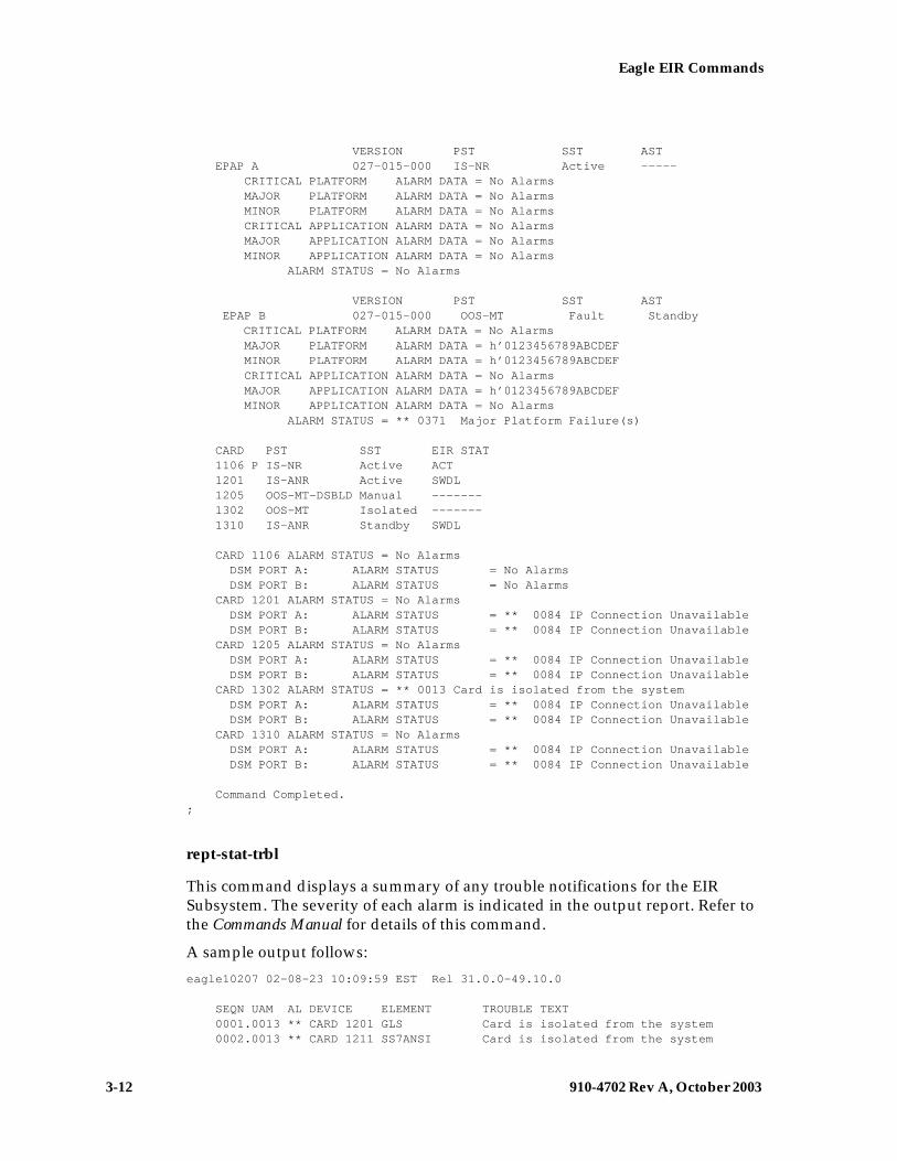
3-12 910-4702 Rev A, October 2003
Eagle EIR Commands
— Draft —
VERSION PST SST AST EPAP A 027-015-000 IS-NR Active ----- CRITICAL PLATFORM ALARM DATA = No Alarms MAJOR PLATFORM ALARM DATA = No Alarms MINOR PLATFORM ALARM DATA = No Alarms CRITICAL APPLICATION ALARM DATA = No Alarms MAJOR APPLICATION ALARM DATA = No Alarms MINOR APPLICATION ALARM DATA = No Alarms ALARM STATUS = No Alarms
VERSION PST SST AST EPAP B 027-015-000 OOS-MT Fault Standby
CRITICAL PLATFORM ALARM DATA = No Alarms MAJOR PLATFORM ALARM DATA = h’0123456789ABCDEF MINOR PLATFORM ALARM DATA = h’0123456789ABCDEF CRITICAL APPLICATION ALARM DATA = No Alarms MAJOR APPLICATION ALARM DATA = h’0123456789ABCDEF MINOR APPLICATION ALARM DATA = No Alarms ALARM STATUS = ** 0371 Major Platform Failure(s)
CARD PST SST EIR STAT 1106 P IS-NR Active ACT 1201 IS-ANR Active SWDL 1205 OOS-MT-DSBLD Manual ------- 1302 OOS-MT Isolated ------- 1310 IS-ANR Standby SWDL
CARD 1106 ALARM STATUS = No Alarms DSM PORT A: ALARM STATUS = No Alarms DSM PORT B: ALARM STATUS = No Alarms CARD 1201 ALARM STATUS = No Alarms DSM PORT A: ALARM STATUS = ** 0084 IP Connection Unavailable DSM PORT B: ALARM STATUS = ** 0084 IP Connection Unavailable CARD 1205 ALARM STATUS = No Alarms DSM PORT A: ALARM STATUS = ** 0084 IP Connection Unavailable DSM PORT B: ALARM STATUS = ** 0084 IP Connection Unavailable CARD 1302 ALARM STATUS = ** 0013 Card is isolated from the system DSM PORT A: ALARM STATUS = ** 0084 IP Connection Unavailable DSM PORT B: ALARM STATUS = ** 0084 IP Connection Unavailable CARD 1310 ALARM STATUS = No Alarms DSM PORT A: ALARM STATUS = ** 0084 IP Connection Unavailable DSM PORT B: ALARM STATUS = ** 0084 IP Connection Unavailable
Command Completed.;
rept-stat-trbl
This command displays a summary of any trouble notifications for the EIR Subsystem. The severity of each alarm is indicated in the output report. Refer to the Commands Manual for details of this command.
A sample output follows:
eagle10207 02-08-23 10:09:59 EST Rel 31.0.0-49.10.0 SEQN UAM AL DEVICE ELEMENT TROUBLE TEXT 0001.0013 ** CARD 1201 GLS Card is isolated from the system 0002.0013 ** CARD 1211 SS7ANSI Card is isolated from the system

Eagle EIR Commands
910-4702 Rev A, October 2003 3-13
— Draft —
0011.0013 ** CARD 1101 SCCP Card is isolated from the system 0013.0013 ** CARD 1103 GLS Card is isolated from the system 0015.0013 ** CARD 1105 VSCCP Card is isolated from the system 0018.0013 ** CARD 1115 OAM Card is isolated from the system 0019.0236 ** SLK 1211,B ls1134 REPT-LKF: not aligned 0020.0236 ** SLK 1311,A ls1134567 REPT-LKF: not aligned 0021.0236 ** SLK 1312,A ls113456 REPT-LKF: not aligned 0022.0236 ** SLK 1313,A ls11345 REPT-LKF: not aligned 0023.0236 ** SLK 1314,A ls113467 REPT-LKF: not aligned 0024.0236 ** SLK 1315,A ls11234567 REPT-LKF: not aligned 0025.0236 ** SLK 1316,A ls11345678 REPT-LKF: not aligned 0026.0318 ** LSN ls11234567 REPT-LKSTO: link set prohibited 0027.0318 ** LSN ls11345678 REPT-LKSTO: link set prohibited 0028.0318 ** LSN ls1134567 REPT-LKSTO: link set prohibited 0029.0318 ** LSN ls113456 REPT-LKSTO: link set prohibited 0030.0318 ** LSN ls11345 REPT-LKSTO: link set prohibited 0031.0318 ** LSN ls113467 REPT-LKSTO: link set prohibited 0032.0318 ** LSN ls1134 REPT-LKSTO: link set prohibited 0033.0336 ** SCCP SYSTEM LIM(s) have been denied SCCP service 0034.0349 *C SEAS SYSTEM SEAS unavailable 0035.0356 *C LSMS SYSTEM LSMS unavailable 0036.0455 *C EIR SYSTEM EIR Subsystem is not available 0019.0236 *C T1PORT 1301,1 REPT-T1F:FAC-T1 LOS failure Command Completed.
chg-measopts
The chg-measopts command provides the user with the capability to enable and disable measurement options related to the Measurements Platform. This command is modified to allow the use of the mtcheir and the mtcdeir options to set whether or not the EIR reports will be automatically generated and transferred to the FTP server. By default, both EIR options are disabled and cannot be changed unless the EIR feature is activated. Once the feature is activated, the EIR options can be enabled and disabled as desired. Refer to the Commands Manual for details of this command. .
rept-stat-alm
This command includes the alarm totals of the EIR subsystem and DSM/EPAP IP links. Refer to the Commands Manual for details of this command. Here is an example of the command and output.
rept-stat-alm
Command Accepted - Processing
eagle10605 99-06-24 23:59:39 EST Rel 31.0.0 rept-stat-alm Command entered at terminal #10.;
eagle10605 99-06-24 23:59:39 EST Rel 31.0.0 ALARM TRANSFER= RMC ALARM MODE CRIT= AUDIBLE MAJR= AUDIBLE MINR= AUDIBLE ALARM FRAME 1 CRIT= 9 MAJR= 12 MINR= 2 ALARM FRAME 2 CRIT= 0 MAJR= 0 MINR= 0 ALARM FRAME 3 CRIT= 0 MAJR= 0 MINR= 0

3-14 910-4702 Rev A, October 2003
Eagle EIR Commands
— Draft —
ALARM FRAME 4 CRIT= 0 MAJR= 0 MINR= 0 ALARM FRAME 5 CRIT= 0 MAJR= 0 MINR= 0 ALARM FRAME 6 CRIT= 0 MAJR= 0 MINR= 0 ALARM FRAME GPF CRIT= 1 MAJR= 2 MINR= 1 PERM. INH. ALARMS CRIT= 0 MAJR= 0 MINR= 0 TEMP. INH. ALARMS CRIT= 0 MAJR= 0 MINR= 0 ACTIVE ALARMS CRIT= 10 MAJR= 14 MINR= 3 TOTAL ALARMS CRIT= 10 MAJR= 14 MINR= 3 Command Completed.;
rept-stat-db
This command displays the status information for the Eagle System databases. This includes the level information for each DSM network card, and for the active and standby EPAP databases. It reports database exception status such as corrupted, incoherent, or inconsistent, as well as providing the birthdates and levels. It is enhanced to show the status of the PDB and RTDB databases if the EIR feature key is on. For details about this command, refer to the Commands Manual.
inh-card / alw-card
The inh-card command is used to change the state of the card from in-service normal (IS-NR) to Out-of-Service Maintenance-Disabled (OOS-MT-DSBLD). A craftsperson then can test the DCM/LIM/ACM/ASM/DSM/GPSM-II/MIM card or physically remove it from the shelf.
The alw-card command is used to change the card from OOS-MT-DSBLD (out-of-service maintenance-disabled) to IS-NR (in-service normal) if the loading is successful.
Refer to the Commands Manual for details of these commands.
ent-card / rtrv-card / dlt-card
The command-handling and scroll area output for these commands includes the DSM card. For the ent-card command, the appl=vsccp is supported. Refer to the Commands Manual for details of this command.
If the addition of a LIM card exceeds the system’s VSCCP service capabilities, the force=yes parameter is required.
Here is a sample of the reports produced by these commands.
ent-card:loc=1201:type=dsm:appl=vsccp
Command entered at terminal #3.; Command Completed.;

Eagle EIR Commands
910-4702 Rev A, October 2003 3-15
— Draft —
alw-map-ss / inh-map-ss
The alw-map-ss command is used to allow the EIR subsystem which brings the subsystem back on-line. The command is rejected if the subsystem specified with the SSN parameter is not the EIR subsystem. The current state of the LNPQS, INPQS or EIR subsystem must be OOS-MT-DSBLD (out of service maintenance disabled) in order for the command to be accepted.
When the inh-map-ss is entered for the EIR subsystem, a coordinated shutdown is attempted. If the coordinated shutdown fails, a UIM is output indicating the shutdown failed. If the FORCE parameter is specified, the specified subsystem is forced to shutdown. A coordinated shutdown is not performed.
Refer to the Commands Manual for details of these commands.
ent-map / chg-map / dlt-map
These commands are used to provision, remove, change, and report on the mate point code and subsystem number and its attributes. A mate point code defines an adjacent signaling point, which is considered the mated signal transfer point (STP) to the Eagle.
These commands are updated to allow both ITU-N and ITU-I true point codes to be defined for the same SSN. Refer to the Commands Manual for details of these commands.
chg-sid / dlt-sid
These commands are used to change and report on the self-identification of the Eagle system. The self-identification identifies the Eagle to other signaling points in the network. This command adds new CPC type for EIR. Refer to the Commands Manual for details of this command.
ent-ss-appl / chg-ss-appl / dlt-ss-appl / rtrv-ss-appl
These commands are used to provision, remove, change, and report on the entry of a subsystem number for an application and set the application status online or offline. Only one subsystem can be defined per application, and the application must be unique. This command adds new subsystem application value for EIR. Refer to the Commands Manual for details of these commands.
ent-card
This command now verifies that if the EIR feature is turned on, that the gpl that is being provisioned is a VSCCP gpl, and if it is, an error is displayed and the ent-card command is rejected.

3-16 910-4702 Rev A, October 2003
Eagle EIR Commands
— Draft —
chg-gpl / act-gpl / rtrv-gpl / rept-stat-gpl / copy-gpl
The command-handling and scroll area output for these commands include the VSCCP GPL. Refer to the Commands Manual for details of these commands.
Here are samples of the reports produced by these commands.
chg-gpl:appl=vsccp:ver=101-3-0
Command entered at terminal #3.; tekelecstp 99-10-24 06:54:39 EST Rel 31.0.0 VSCCP upload to 1114 completed VSCCP upload to 1116 completed;
act-gpl:appl=vsccp:ver=101-3-0
Command entered at terminal #3.; tekelecstp 99-10-24 06:54:39 EST Rel 30.1.0 VSCCP activate on 1114 completed VSCCP activate on 1116 completed;
rtrv-gpl:appl=vsccp
Command entered at terminal #3.; tekelecstp 99-10-04 07:01:08 EST Rel 31.0.0 GPL Auditing ON
APPL CARD RELEASE APPROVED TRIAL REMOVE TRIAL VSCCP 1114 101-001-000 101-003-000 101-001-000 101-003-000 VSCCP 1116 101-001-000 101-003-000 101-003-000 -----------;
rept-stat-gpl:appl=vsccp
Command entered at terminal #3.; tekelecstp 99-10-04 12:55:50 EST Rel 25.0.0 APPL CARD RUNNING APPROVED TRIAL VSCCP 1205 101-003-000 ALM 101-003-000 101-003-000 VSCCP 1211 101-001-000 ALM+ 101-003-000 ----------- Command Completed.;
inh-alm / unhb-alm
These commands allow both Port A and Port B to be specified for the dev=dlk. This allows alarms to be inhibited on the DSM ports. Refer to the Commands Manual for details of these commands.

Eagle EIR Commands
910-4702 Rev A, October 2003 3-17
— Draft —
rept-ftp-meas
This command provides on-demand measurements reporting capabilities. this command initiates generation and FTP transfer of a measurements report from the MCPM to the FTP server. The rept-ftp-meas command is modified to accept a new EIR enttype. The combination of this enttype and a report type determines which on-demand EIR report is generated. There are only two report types that are accepted in conjunction with enttype=eir: MTCH and MTCD. The EIR enttype is only valid with the EIR feature enabled. Refer to the Commands Manual for details of this command.
rtrv-measopts / chg-measopts
The chg-measopts command provides the user with the capability to enable and disable measurement options related to the Measurements Platform. This command is modified to allow the use of the mtcheir and the mtcdeir options to set whether or not the EIR reports will be automatically generated and transferred to the FTP server. By default, both EIR options are disabled and cannot be changed unless the EIR feature is activated. Once the feature is activated, the EIR options can be enabled and disabled as desired.
The rtrv-measopts command displays the current state of the Measurements Platform options. The output of this command is modified to display the status of the EIR report options.
Refer to the Commands Manual for details of these commands.

3-18 910-4702 Rev A, October 2003
Eagle EIR Commands
— Draft —

910-4702 Rev A, October 2003 4-1
— Draft —
4
EIR Configuration
Introduction...................................................................................................... 4–2
Adding a DSM ................................................................................................. 4–3
Removing a DSM..............................................................................................4-9
Enabling and Activating the EIR Feature................................................... 4–12
Adding the EIR Subsystem Application .....................................................4-22
Removing the EIR Subsystem Application................................................ 4–28
Changing a Subsystem Application............................................................ 4–32
Adding an EIR Service Selector ................................................................... 4–39
Removing the EIR Subsystem Application................................................ 4–28
Changing an Existing Non-EIR Service Selector to an EIR Service Selector .............................................................................................4-50
Changing the EIR Options ........................................................................... 4–57

4-2 910-4702 Rev A, October 2003
EIR Configuration
— Draft —
Introduction
The EIR feature is configured on the Eagle and on the EPAP (in association with either the G-FLEX or G-PORT features). This chapter covers the Eagle configuration only. The EPAP configuration is covered in the EPAP Administration Manual.
The Eagle configuration of the EIR feature consists of the following:
• The Eagle must contain DSMs running the VSCCP application – This can be verified with the rtrv-card command. To add DSMs, see the “Adding a DSM” procedure on page 4-3.
• The EIR feature must be enabled and activated – This can be verified with the rtrv-ctrl-feat command. To enable and actviate the EIR feature, see the “Enabling and Activating the EIR Feature” procedure on page 4-12.
• Change the self ID of the Eagle to include EIR capability point codes – This can be verified with the rtrv-sid command. To provision EIR capability point codes, see the “Changing the Self-Identification of the System” procedure in the Database Administration Manual - SS7.
• Mated applications containing the Eagle’s ITU-I and ITU-N true point code, the EIR capability point codes, and the EIR subsystem number. This can be verified with the rtrv-map command. To provision mated applications for the EIR feature, see the “Provisioning a Mated Application” or “Changing a Mated Application” procedures in the Database Administration Manual - Global Title Translation.
• The EIR subsystem application number, verified with the rtrv-ss-appl command. To configure the EIR subsystem application number, see the “Adding the EIR Subsystem Application” procedure on page 4-22 or the “Changing a Subsystem Application” procedure on page 4-32.
• The GSM Service Selector, verified with the rtrv-srvsel command. To configure GSM Service Selectors, see the “Adding an EIR Service Selector” procedure on page 4-39.
• The EIR Global Response status, EIR Response Type, and EIR IMSI Check status options, verified with the rtrv-gsmopts command, can be changed. To change these options, see the “Changing the EIR Options” procedure on page 4-57.

EIR Configuration
910-4702 Rev A, October 2003 4-3
— Draft —
Adding a DSM
This procedure is used to add a DSM to support the Global Title Translation or Enhanced Global Title Translation feature, and the EIR feature to the database using the ent-card command.
A DSM can be one of the following:
• DSM 1G – a DSM with 1 gigabyte of memory
• DSM 2G – a DSM with 2 gigabyte of memory
• DSM 3G – a DSM with 3 gigabyte of memory
• DSM 4G – a DSM with 4 gigabyte of memory
NOTE: Cards running the SCCP application (TSMs and ASMs) cannot be used with the EIR feature. If any cards running the SCCP application are present in the system, they must be replaced by DSMs. Contact Tekelec Technical Services before replacing any cards running the SCCP application. See “Tekelec Technical Services” on page 1-9.
The DSM can be inserted only in the odd numbered card slots of the extension shelf. Slot 09 of each shelf contains the HMUX card, thus the DSM cannot be inserted in slot 09. The DSM can be inserted in the control shelf, but only in slots 01, 03, 05, and 07. The DSM occupies two card slots, so the even numbered card slot to the right of the odd numbered slot where the DSM has been inserted must be empty, as shown in Table 4-1. The DSM is connected to the network through the odd numbered card slot connector.
The ent-card command uses these parameters.
:loc – The location of the card being added to the database.
:type – The type of card being added to the database. The value of this parameter is dsm.
:appl – The application software or GPL that is assigned to the card. The value of this parameter is vsccp.
:force – Allow the LIM to be added to the database even if there are not enough DSMs to support the number of LIMs in the system. This parameter does not apply to configuring DSMs and should not be used.
Table 4-1. DSM Card Locations
Location of the DSM
Empty Card Location
Location of the DSM
Empty Card Location
Slot 01 Slot 02 Slot 11 Slot 12
Slot 03 Slot 04 Slot 13 Slot 14
Slot 05 Slot 06 Slot 15 Slot 16
Slot 07 Slot 08 Slot 17 Slot 18

4-4 910-4702 Rev A, October 2003
EIR Configuration
— Draft —
The shelf to which the card is to be added, must already be in the database. This can be verified with the rtrv-shlf command. If the shelf is not in the database, see the “Adding a Shelf” procedure in the Database Administration Manual – System Management.
The card cannot be added to the database if the specified card location already has a card assigned to it.
The system can contain a maximum of 25 DSMs.
The amount of memory required on these DSMs is determined by the directory number, IMSI, and IMEI quantities contained in the EIR portion of the database.
Procedure 4-1. Adding a DSM
1. Verify that the GTT feature is on, by entering the rtrv-feat command. If the GTT feature is on, the GTT field should be set to on. For this example, the GTT feature is off.
NOTE: The rtrv-feat command output contains other fields that are not used by this procedure. If you wish to see all the fields displayed by the rtrv-feat command, see the rtrv-feat command description in the Commands Manual.
NOTE: If the GTT feature is on, shown by the entry GTT = on in the rtrv-feat command output in step 1, skip this step and go to step 3.
2. Turn the global title translation feature on by entering this command.
chg-feat:gtt=on
NOTE: Once the Global Title Translation (GTT) feature is enabled with the chg-feat command, it cannot be disabled.
The GTT feature must be purchased before turning it on. If you are not sure whether you have purchased the GTT feature, contact your Tekelec Sales Representative or Account Representative.
When the chg-feat has successfully completed, this message should appear.
rlghncxa03w 03-06-25 09:57:41 GMT Rel 31.0.0CHG-FEAT: MASP A - COMPLTD
3. Display the cards in the system using the rtrv-card command. This is an example of the possible output.
NOTE: Cards should be distributed throughout the system for proper power distribution. Refer to the Installation Manual for the shelf power distribution.

EIR Configuration
910-4702 Rev A, October 2003 4-5
— Draft —
This is an example of the possible output.
rlghncxa03w 03-06-25 09:58:31 GMT Rel 31.0.0CARD TYPE APPL LSET NAME PORT SLC LSET NAME PORT SLC1102 ASM GLS ------------ -- -- ------------ -- --1113 GPSM EOAM1114 TDM-A1115 GPSM EOAM1116 TDM-B1117 MDAL1118 RESERVED1201 LIMDS0 SS7ANSI sp2 A 0 sp1 B 01203 LIMDS0 SS7ANSI sp3 A 0 ------------ -- --1204 LIMDS0 SS7ANSI sp3 A 1 ------------ -- --1206 LIMDS0 SS7ANSI nsp3 A 1 nsp4 B 11207 LIMV35 SS7GX25 nsp1 A 0 ------------ -- --1208 LIMV35 SS7GX25 nsp1 A 1 ------------ -- --1216 ACMENET STPLAN ------------ -- -- ------------ -- --1308 LIMDS0 SS7ANSI sp6 A 1 sp7 B 01314 LIMDS0 SS7ANSI sp7 A 1 sp5 B 11317 ACMENET STPLAN ------------ -- -- ------------ -- --
4. Verify that the DSM has been physically installed into the proper location. If any cards running the SCCP application (ASMs or TSMs) are present in the system, they must be replaced by DSMs. Contact Tekelec Technical Services before replacing any cards running the SCCP application. See “Customer Assistance” on page 1-7.
CAUTION: If the version of the BPDCM GPL on the DSM card does not match the BPDCM GPL version in the database when the DSM is inserted into the card slot, UAM 0002 is generated indicating that these GPL versions do not match. If UAM 0002 has been generated, perform the alarm clearing procedure for UAM 0002 in the Maintenance Manual before proceeding with this procedure.
5. Add the DSM to the database using the ent-card command. For this example, enter this command.
ent-card:loc=1301:type=dsm:appl=vsccp
When this command has successfully completed, this message should appear.
rlghncxa03w 03-06-25 09:57:51 GMT Rel 31.0.0ENT-CARD: MASP A - COMPLTD
6. Verify the changes using the rtrv-card command with the card location specified. For this example, enter this command.
rtrv-card:loc=1301
This is an example of the possible output.
rlghncxa03w 03-06-25 09:58:31 GMT Rel 31.0.0CARD TYPE APPL LSET NAME PORT SLC LSET NAME PORT SLC1301 DSM VSCCP ------------ -- -- ------------ -- --

4-6 910-4702 Rev A, October 2003
EIR Configuration
— Draft —
NOTE: If the EGTT feature is on, shown by the entry EGTT = on in the rtrv-feat command output in step 1, or if the EGTT feature is off and will not be enabled in this procedure, skip this step and go to step 9.
7. Turn the enhanced global title translation feature on by entering this command.
chg-feat:egtt=on
NOTE: Once the Enhanced Global Title Translation (EGTT) feature is enabled with the chg-feat command, it cannot be disabled.
The EGTT feature must be purchased before turning it on. If you are not sure whether you have purchased the EGTT feature, contact your Tekelec Sales Representative or Account Representative.
When the chg-feat has successfully completed, this message should appear.
rlghncxa03w 03-06-25 09:57:41 GMT Rel 31.0.0CHG-FEAT: MASP A - COMPLTD
8. Backup the new changes using the chg-db:action=backup:dest=fixed command. These messages should appear, the active Maintenance and Administration Subsystem Processor (MASP) appears first.
BACKUP (FIXED) : MASP A - Backup starts on active MASP.BACKUP (FIXED) : MASP A - Backup on active MASP to fixed disk complete.BACKUP (FIXED) : MASP A - Backup starts on standby MASP.BACKUP (FIXED) : MASP A - Backup on standby MASP to fixed disk complete.

EIR Configuration
910-4702 Rev A, October 2003 4-7
— Draft —
Flowchart 4-1. Adding a DSM (Sheet 1 of 2)
NOTE: Before executing this procedure, make sure you have purchased the Global Title Translation (GTT) and Enhanced Global Title Translation (EGTT) (if the EGTT feature is being enabled) features. If you are not sure whether you have purchased the GTT and EGTT features, contact your Tekelec Sales Representative or Account Representative.
Enter thertrv-feat command
To Sheet2
Enter thechg-feat:gtt=on
command
Is the global titletranslation feature on?
Enter the rtrv-cardcommand
No
Yes
Are there any cardsassigned the card type ASM
and running the SCCP GPL inthe database?
Yes
No
Replace the cards running the SCCPapplication with DSMs. Contact TekelecTechnical Services before replacing any
cards running the SCCP application.See “Tekelec Technical Services”
section in Chapter 1.

4-8 910-4702 Rev A, October 2003
EIR Configuration
— Draft —
Flowchart 4-1. Adding a DSM (Sheet 2 of 2)
Enter thechg-db:action=backup:dest=fixed
command
FromSheet 1
Has the DSMbeen installed?
Insert the DSM into an oddnumbered card slot with
the adjacent even card slotempty
No
Yes
Has UAM 0002 beengenerated?
Yes
No
Go to the alarm clearingprocedure for UAM 0002 in theMaintenance Manual and clear
the alarm
Enter thertrv-card:loc=<card location
specified in ent-cardcommand> command
Enter theent-card:loc=<card location>
:type=dsm:appl=vsccpcommand
Is the EnhancedGlobal Title Translation
(EGTT) feature on?
Is the EnhancedGlobal Title Translation
(EGTT) to be turnedon?
Enter thechg-feat:egtt=on
command
YesYes
NoNo

EIR Configuration
910-4702 Rev A, October 2003 4-9
— Draft —
Removing a DSM
This procedure is used to remove DSMs, used by the global title translation and EIR features, from the database using the dlt-card command. The card cannot be removed if it does not exist in the database.
CAUTION: If the DSM is the last DSM in service, removing this card from the database will cause global title translation and EIR traffic to be lost.
The DSM is shown in the database with the entries DSM in the TYPE field and VSCCP in the APPL field or the of the rtrv-card command output
The examples in this procedure are used to remove the DSM in card location 1204.
Procedure 4-2. Removing a DSM
1. Display the status of the DSMs by entering the rept-stat-sccp command. This is an example of the possible output.
rlghncxa03w 03-06-12 09:12:36 GMT Rel 31.0.0SCCP SUBSYSTEM REPORT IS-NR Active ----- SCCP Cards Configured= 5 Cards IS-NR= 5 Capacity Threshold = 100% CARD VERSION PST AST MSU SST CPU USAGE ------------------------------------------------------------------ 1204 113-002-001 IS-NR ALMINH Active 81% 1208 113-002-001 IS-NR ALMINH Active 50% 2101 113-002-001 IS-NR ALMINH Active 29% 2105 113-002-001 IS-NR ALMINH Active 52% 2112 113-002-001 IS-NR ALMINH Active 71% ------------------------------------------------------------------SCCP Service Average Capacity = 56%Command Completed.
2. Remove the card from service using the rmv-card command and specifying the card location. If the DSM to be inhibited is the only DSM in service, the force=yes parameter must also be specified. The cards that are in service are shown by the entry IS-NR in the PST field in the output in step 1. For this example, enter this command.
rmv-card:loc=1204
When this command has successfully completed, this message should appear.
rlghncxa03w 03-06-12 09:12:36 EST Rel 31.0.0Card has been inhibited.
3. Remove the card from the database using the dlt-card command. The dlt-card command has only one parameter, loc, which is the location of the card. For this example, enter this command.
dlt-card:loc=1204

4-10 910-4702 Rev A, October 2003
EIR Configuration
— Draft —
When this command has successfully completed, this message should appear.
rlghncxa03w 03-06-12 09:12:36 EST Rel 31.0.0DLT-CARD: MASP A - COMPLTD
4. Verify the changes using the rtrv-card command specifying the card that was removed in step 3. For this example, enter this command.
rtrv-card:loc=1204
When this command has successfully completed, this message should appear.
E2144 Cmd Rej: Location invalid for hardware configuration
5. Backup the new changes using the chg-db:action=backup:dest=fixed command. These messages should appear, the active Maintenance and Administration Subsystem Processor (MASP) appears first.
BACKUP (FIXED) : MASP A - Backup starts on active MASP.BACKUP (FIXED) : MASP A - Backup on active MASP to fixed disk complete.BACKUP (FIXED) : MASP A - Backup starts on standby MASP.BACKUP (FIXED) : MASP A - Backup on standby MASP to fixed disk complete.

EIR Configuration
910-4702 Rev A, October 2003 4-11
— Draft —
Flowchart 4-2. Removing a DSM
Is the DSMbeing removed the only
one in service?
No
Enter thechg-db:action=backup:dest=fixed
command
Enter the rtrv-card:loc=<location specified in thedlt-card command> command
Enter the dlt-card:loc=<location of the DSMbeing removed> command
Enter the rept-stat-sccpcommand
Yes
Enter thermv-card:loc=<location of
the DSM beingremoved>:force=yes
command
Enter the rmv-card:loc=<locationof the DSM being removed>
command
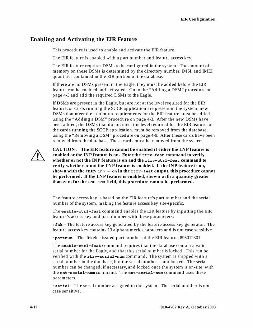
4-12 910-4702 Rev A, October 2003
EIR Configuration
— Draft —
Enabling and Activating the EIR Feature
This procedure is used to enable and activate the EIR feature.
The EIR feature is enabled with a part number and feature access key.
The EIR feature requires DSMs to be configured in the system. The amount of memory on these DSMs is determined by the directory number, IMSI, and IMEI quantities contained in the EIR portion of the database.
If there are no DSMs present in the Eagle, they must be added before the EIR feature can be enabled and activated. Go to the “Adding a DSM” procedure on page 4-3 and add the required DSMs to the Eagle.
If DSMs are present in the Eagle, but are not at the level required for the EIR feature, or cards running the SCCP application are present in the system, new DSMs that meet the minimum requirements for the EIR feature must be added using the “Adding a DSM” procedure on page 4-3. After the new DSMs have been added, the DSMs that do not meet the level required for the EIR feature, or the cards running the SCCP application, must be removed from the database, using the “Removing a DSM” procedure on page 4-9. After these cards have been removed from the database, These cards must be removed from the system.
CAUTION: The EIR feature cannot be enabled if either the LNP feature is enabled or the INP feature is on. Enter the rtrv-feat command to verify whether or not the INP feature is on and the rtrv-ctrl-feat command to verify whether or not the LNP feature is enabled. If the INP feature is on, shown with the entry inp = on in the rtrv-feat output, this procedure cannot be performed. If the LNP feature is enabled, shown with a quantity greater than zero for the LNP TNs field, this procedure cannot be performed.
The feature access key is based on the EIR feature’s part number and the serial number of the system, making the feature access key site-specific.
The enable-ctrl-feat command enables the EIR feature by inputting the EIR feature’s access key and part number with these parameters:
:fak – The feature access key generated by the feature access key generator. The feature access key contains 13 alphanumeric characters and is not case sensitive.
:partnum – The Tekelec-issued part number of the EIR feature, 893012301.
The enable-ctrl-feat command requires that the database contain a valid serial number for the Eagle, and that this serial number is locked. This can be verified with the rtrv-serial-num command. The system is shipped with a serial number in the database, but the serial number is not locked. The serial number can be changed, if necessary, and locked once the system is on-site, with the ent-serial-num command. The ent-serial-num command uses these parameters.
:serial – The serial number assigned to the system. The serial number is not case sensitive.

EIR Configuration
910-4702 Rev A, October 2003 4-13
— Draft —
:lock – Specifies whether or not the serial number is locked. This parameter has only one value, yes, which locks the serial number. Once the serial number is locked, it cannot be changed.
Once the EIR feature has been enabled, the EIR feature must be activated with the chg-ctrl-feat command. The chg-ctrl-feat command uses these parameters:
:partnum – The Tekelec-issued part number of the EIR feature, 893012301.
:status=on – used to activate the controlled features that customer has purchased and enabled.
The status of the controlled features in the system is shown with the rtrv-ctrl-feat command.
NOTE: Once the EIR feature is enabled and activated, the EIR feature cannot be disabled. When the EIR feature is enabled, it is permantly enabled. The EIR feature cannot be temporarily enabled.
The feature access key for the desired EIR telephone number quantity must be purchased before you enable the EIR feature. If you are not sure if you have purchased the EIR feature access key, contact your Tekelec Sales Representative or Account Representative.
Procedure 4-3. Enabling and Activating the EIR Feature
1. Display the status of the controlled features by entering the rtrv-ctrl-feat command. The following is an example of the possible output.
rlghncxa03w 03-06-30 21:15:37 GMT Rel 31.0.0The following features have been permanently enabled:Feature Name Partnum Status QuantityTPS 893000110 on 1000ISUP Normalization 893000201 on ----Command Class Management 893005801 off ----LNP Short Message Service 893006601 off ----Intermed GTT Load Sharing 893006901 off ----XGTT Table Expansion 893006101 off ----XMAP Table Expansion 893007710 on 3000Large System # Links 893005910 on 2000Routesets 893006401 on 6000
The following features have been temporarily enabled:Feature Name Partnum Status Quantity Trial Period LeftTPS 893000140 on 4000 20 days 8 hrs 57 mins
The following features have expired temporary keys:Feature Name Part NumZero entries found.
If the EIR feature is enabled and activated, performing this procedure is not necessary.

4-14 910-4702 Rev A, October 2003
EIR Configuration
— Draft —
If the rtrv-ctrl-feat output shows that the LNP telephone number quantity is greater than zero, this procedure cannot be performed.
2. Verify that the INP feature is off, by entering the rtrv-feat command. The EIR feature cannot be enabled is the INP feature is on. If the INP feature is off, the INP field should be set to off.
NOTE: The rtrv-feat command output contains other fields that are not used by this procedure. If you wish to see all the fields displayed by the rtrv-feat command, see the rtrv-feat command description in the Commands Manual.
If the INP feature is on, this procedure cannot be performed.
NOTE: If the rtrv-feat output in step 2 shows that the global title translation (GTT ) is on, skip this step and go to step 4.
3. Turn the GTT feature on by entering this command.
chg-feat:gtt=on
NOTE: Once the GTT feature is turned on with the chg-feat command, it cannot be turned off.
The GTT feature must be purchased before you turn the feature on with the chg-feat command. If you are not sure if you have purchased the GTT feature, contact your Tekelec Sales Representative or Account Representative.
When the chg-feat has successfully completed, this message should appear.
rlghncxa03w 03-06-07 00:57:31 GMT Rel 31.0.0CHG-FEAT: MASP A - COMPLTD
4. The EIR feature requires that DSMs must be configured in the database. Display the cards in the database with the rtrv-card command. The ASMs and TSMs are shown with the entries ASM in the TYPE field and SCCP in the APPL field. The DSMs are shown with the entries DSM in the TYPE field and VSCCP in the APPL field. This is an example of the possible output.
rlghncxa03w 03-06-07 00:57:31 GMT Rel 31.0.0CARD TYPE APPL PORT A LSET (SLC) PORT B LSET (SLC)1101 DSM VSCCP -------- (--) -------- (--)1113 GPSM EOAM1114 TDM-A1115 GPSM EOAM1116 TDM-B1117 MDAL1118 RESERVED1201 LIMDS0 SS7ANSI sp2 (00) sp1 (00)1214 ASM GLS -------- (--) -------- (--)1216 ACMENET STPLAN -------- (--) -------- (--)1305 LIMDS0 SS7ANSI sp5 (00) sp6 (00)

EIR Configuration
910-4702 Rev A, October 2003 4-15
— Draft —
If DSMs are not shown in the output of the rtrv-card command, go to the “Adding a DSM” procedure on page 4-3 and add the necessary DSMs, making sure that the DSMs meet the requirements.
If the rtrv-card output shows cards running the SCCP application, these cards must be removed after the DSMs are added to the database. Go the “Removing a DSM” procedure on page 4-9 and remove all the cards running the SCCP application from the database.
NOTE: If the rtrv-card output in step 4 did not contain DSMs, skip step 5 and go to step 6.
5. Choose one of the DSMs shown in the rtrv-card output in step 4. Display the amount of memory on the DSM, using the rept-stat-card command specifying the card location of the DSM, and the mode=full parameter. For this example, enter this command.
rept-stat-card:loc=1101:mode=full
This is an example of the possible output.
tekelecstp 03-06-17 14:12:27 EST Rel 31.0.0CARD VERSION TYPE APPL PST SST AST1101 118-021-001 DSM VSCCP IS-NR Active ----- ALARM STATUS = No Alarms IMT VERSION = 118-021-000 PROM VERSION = 028-002-001 IMT BUS A = Conn IMT BUS B = Conn CLOCK A = Idle CLOCK B = Idle CLOCK I = Active MBD BIP STATUS = valid DB STATUS = valid DBD MEMORY SIZE = 1024M HW VERIFICATION CODE = ----- SCCP % OCCUP = 10% SNM TVG RESULT = 24 hr: ------, 5 min: ------Command Completed.
The amount of memory on the DSM is shown in the DBD MEMORY SIZE field. If the amount of memory does not meet the requirements, perform these steps.
a. Add the DSM that meet the requirements to the database using the “Adding a DSM” procedure on page 4-3.
b. Remove the DSM specified in the rept-stat-card command from the database using the “Removing a DSM” procedure on page 4-9.
c. Remove the card specified in substep b from the Eagle.
Repeat this step for all DSMs shown in the rtrv-card output in step 4.
NOTE: If the rtrv-ctrl-feat output in step 1 shows any controlled features, skip steps 6 and 7, and go to step 8.

4-16 910-4702 Rev A, October 2003
EIR Configuration
— Draft —
6. Display the serial number in the database with the rtrv-serial-num command. This is an example of the possible output.
rlghncxa03w 03-06-30 21:15:37 GMT Rel 31.0.0System serial number = ntxxxxxxxxxxxxx
System serial number is not locked.
rlghncxa03w 03-06-30 21:15:37 GMT Rel 31.0.0Command Completed
NOTE: If the serial number is locked, skip step 7 and go to step 8.
7. If the serial number shown in step 6 is not correct and not locked, enter the correct serial number into the database and lock the serial number using the ent-serial-num command with the serial and lock parameters.
If the serial number is correct, but is not locked, enter the ent-serial-num command specifying the serial number shown in step 6 with the lock=yes parameter.
For this example, enter this command.
ent-serial-num:serial=<system serial number>:lock=yes
When this command has successfully completed, the following message should appear.
rlghncxa03w 03-06-30 21:15:37 GMT Rel 31.0.0ENT-SERIAL-NUM: MASP A - COMPLTD
8. Enable the EIR feature by entering the enable-ctrl-feat command. For this example, enter this command.
enable-ctrl-feat:partnum=893012301:fak=<feature access key>
NOTE: The values for the feature access key (the fak parameter) are provided by Tekelec. If you do not have the controlled feature part number or the feature access key for the feature you wish to enable, contact your Tekelec Sales Representative or Account Representative.
When the enable-ctrl-feat command has successfully completed, this message should appear.
rlghncxa03w 03-06-30 21:15:37 GMT Rel 31.0.0ENABLE-CTRL-FEAT: MASP B - COMPLTD
9. The EIR feature enabled in step 7 must be activated using the chg-ctrl-feat command, specifying the EIR feature part number used in step 7 and the status=on parameter. For this example, enter this command.
chg-ctrl-feat:partnum=893012301:status=on
When this command has successfully completed, the following message should appear.
rlghncxa03w 03-06-28 21:15:37 GMT Rel 31.0.0CHG-CTRL-FEAT: MASP B - COMPLTD

EIR Configuration
910-4702 Rev A, October 2003 4-17
— Draft —
10. Verify the changes by entering the rtrv-ctrl-featcommand with the part number specified in step 9.
rtrv-ctrl-feat:partnum=893012301
The following is an example of the possible output.
rlghncxa03w 03-06-30 21:16:37 GMT Rel 31.0.0The following features have been permanently enabled:Feature Name Partnum Status QuantityEIR 893012301 on ------
11. Backup the new changes using the chg-db:action=backup:dest=fixed command. These messages should appear, the active Maintenance and Administration Subsystem Processor (MASP) appears first.
BACKUP (FIXED) : MASP A - Backup starts on active MASP.BACKUP (FIXED) : MASP A - Backup on active MASP to fixed disk complete.BACKUP (FIXED) : MASP A - Backup starts on standby MASP.BACKUP (FIXED) : MASP A - Backup on standby MASP to fixed disk complete.

4-18 910-4702 Rev A, October 2003
EIR Configuration
— Draft —
Flowchart 4-3. Enabling and Activating the EIR Feature (Sheet 1 of 4)
NOTE: Before executing this procedure, make sure you have purchased the global title translation (GTT) feature and the feature access key for the EIR feature. If you are not sure if you have purchased the GTT feature or the EIR feature access key, contact your Tekelec Sales Representative or Account Representative.
Has the amountof memory in all DSMs
shown in the rtrv-card outputbeen verified?
Does the DSM containthe correct amount of memory to
continue this procedure?
Go to the "Removing a DSM" procedure inthis chapter and remove the DSM
specified in the rept-stat-card commandfrom the database
Go to the "Adding a DSM" procedure inthis chapter and add the required DSM
according to the EIR HardwareConfiguration tables in the "Adding a
DSM" procedure
Enter therept-stat-card:loc=<DSMcard location>:mode=full
command
FromSheet 1
Choose anotherDSM shown in the
rtrv-card output
ToSheet 4
Yes
No
No
Yes
Remove the DSM specifiedin the previous step from
the shelf.
Enter thertrv-card command
Are DSMs shown inthe rtrv-card output?
ToSheet 3
Yes
No
Add DSM?
Yes
No

EIR Configuration
910-4702 Rev A, October 2003 4-19
— Draft —
Flowchart 4-3. Enabling and Activating the EIR Feature (Sheet 2 of 4)
Is the INPfeature on?
Is the LNP TNsQuantity greater than
zero (0)?
This procedure cannot beperformed. The EIR feature
cannot be enabled andactivated if the INP feature is
on.
Enter the rtrv-ctrl-featcommand
No
No
Yes
Yes
Enter the rtrv-featcommand
This procedure cannot beperformed. The EIR feature
cannot be enabled andactivated if the LNP feature is
enabled.
Is the EIRfeature enabled and
activated?
No
YesThe EIR feature is already
enabled and activated.This procedure cannot be
performed.
ToSheet 2
Is the GTTfeature on?
Enter thechg-feat:gtt=on
command
No
Yes

4-20 910-4702 Rev A, October 2003
EIR Configuration
— Draft —
Flowchart 4-3. Enabling and Activating the EIR Feature (Sheet 3 of 4)
Go to the "Removing a DSM" procedure inthis chapter and remove all the cards
running the SCCP application from thedatabase
Go to the "Adding a DSM" procedure inthis chapter and add the required DSMs
according to the EIR HardwareConfiguration tables in the "Adding a DSM"
procedure
FromSheet 2
Remove the cards specifiedin the previous step from the
shelf.
Are cards runningthe SCCP application
shown in the rtrv-card outputon Sheet 2?
ToSheet 4
No
Yes

EIR Configuration
910-4702 Rev A, October 2003 4-21
— Draft —
Flowchart 4-3. Enabling and Activating the EIR Feature (Sheet 4 of 4)
Are any controlledfeatures shown in thertrv-ctrl-feat output?
Yes
No
FromSheets 2
or 3
Enter the rtrv-serial-numcommand
Is the system’sserial number in the
database correct and is theserial number locked?(See Notes 1 and 2)
Yes
NoEnter the ent-serial-num
command with these parameters::serial=<system’s serial number>
:lock=yes
Enter theenable-ctrl-feat
:partnum=<893012301>:fak=<feature access key> command
(See Note 3)
Notes:
1. If the serial number is locked, it cannot be changed.
2. If the serial number is not locked, the controlled feature cannot beenabled.
3. If you do not have the controlled feature part number or the featureaccess key for the controlled feature you wish to enable, contact yourTekelec sales representative or account representative.
Enter thechg-db:action=backup:dest=fixed
command
Enter thertrv-ctrl-feat:partnum=<893012301>
command
Enter thechg-ctrl-feat
:partnum=<893012301:status=oncommand

4-22 910-4702 Rev A, October 2003
EIR Configuration
— Draft —
Adding the EIR Subsystem Application
This procedure is used to reserve a subsystem number for the EIR (equipment identity register) application and place the EIR application either online or offline using the ent-ss-appl command. The ent-ss-appl command uses these parameters.
:appl – the application type, EIR
NOTE: The appl parameter contains the values INP, for reserving a subsystem number for the INP subsystem, and LNP, for reserving a subsystem number for the LNP subsystem. These values cannot be used in this procedure. To reserve a subsystem number for the INP or LNP subsystem, perform the procedures in the Feature Manual - INP or Database Administration Manual - LNP and do not perform this procedure.
:ssn – the EIR subsystem number
:stat – the state of the EIR application
The EIR feature must be enabled and activated. Verify this by entering the rtrv-ctrl-feat command. If the EIR feature is enabled and activated, the status of the EIR feature should be on. If the EIR feature is not enabled and activated, perform the “Enabling and Activating the EIR Feature” procedure on page 4-12.
Only one subsystem number for each application can be defined.
If the stat parameter is not specified, the application will be offline.
The application specified by the appl parameter cannot already be in the database.
Before the subsystem application can be added to the database, the Eagle’s true point code and the subsystem number, for ITU-I and 14-bit ITU-N point codes, must be in the mated application table. The Eagle’s true point code is verified with the rtrv-sid command and is shown in the PCI and PCN fields. The mated application table is displayed with the rtrv-map command. The Eagle’s true point code is shown in the PCI and PCN fields of the rtrv-map command output and the subsystem number is shown in the SSN field of the rtrv-map command output. If the Eagle’s true point code and the subsystem number are not shown in the rtrv-map command output, go to the “Adding a Mated Application” procedure in the Database Administration Manual – Global Title Translation and add the Eagle’s true point code and the subsystem to a mated application.
The example in this procedure reserves the subsystem number 100 for the EIR application and sets the EIR application online.

EIR Configuration
910-4702 Rev A, October 2003 4-23
— Draft —
Procedure 4-4.
1. Verify that the EIR feature is enabled and activated by entering the rtrv-ctrl-feat command. If the EIR feature is enabled and activated, the status of the EIR feature is on. This is an example of the possible output.
rlghncxa03w 03-06-30 21:15:37 GMT Rel 31.0.0The following features have been permanently enabled:Feature Name Partnum Status QuantityTPS 893000110 on 1000ISUP Normalization 893000201 on ----Command Class Management 893005801 off ----Intermed GTT Load Sharing 893006901 off ----XGTT Table Expansion 893006101 off ----XMAP Table Expansion 893007710 on 3000Large System # Links 893005910 on 2000Routesets 893006401 on 6000
The following features have been temporarily enabled:Feature Name Partnum Status Quantity Trial Period LeftTPS 893000140 on 4000 20 days 8 hrs 57 mins
The following features have expired temporary keys:Feature Name Part NumZero entries found.
If the EIR feature is not enabled or activated, perform the “Enabling and Activating the EIR Feature” procedure on page 4-12 to enable and activate the EIR feature. Go to step 2.
If the EIR feature is enabled and activated, go to step 2.
2. Display the subsystem number for the EIR application in the database with the rtrv-ss-appl command. This is an example of the possible output.
rlghncxa03w 03-06-28 14:42:38 GMT Rel 31.0.0APPL SSN STAT
SS-APPL table is (0 of 1) 0% full
3. Display the Eagle’s true point code using the rtrv-sid command. The Eagle’s true point code is shown in the PCA, PCI, PCN, or PCN24 field of the rtrv-sid output. The PCN24 field is displayed only if 24-bit ITU-N point codes are being used. The PCN field is displayed only if 14-bit ITU-N point codes are being used. Either the PCN or PCN24 fields will be displayed, but both fields will not be displayed at the same time. The EIR feature requires ITU-I (PCI) and ITU-N (PCN) true point codes.

4-24 910-4702 Rev A, October 2003
EIR Configuration
— Draft —
The following is an example of the possible output.
rlghncxa03w 03-06-10 11:43:04 GMT Rel 31.0.0PCA PCI PCN CLLI PCTYPE100-100-100 3-75-7 7-9-8-1 rlghncxa03w OTHER
CPCA002-002-002 002-002-003 002-002-004 002-002-005002-002-006 002-002-007 002-002-008 002-002-009004-002-001 004-003-003 050-060-070
CPCI1-002-1 1-002-2 1-002-3 1-002-42-001-1 7-222-7
CPCN2-0-10-3 2-0-11-0 2-0-11-2 2-0-12-12-2-3-3 2-2-4-0 10-14-10-1
If the rtrv-sid output does not show entries in the PCI or PCN fields, or if the values of the PCI or PCN fields need to be changed, perform the “Changing the Self-Identification of the System” procedure in the Database Administration Manual - SS7 to add the correct PCI and PCN values.
4. Display the mated applications using the rtrv-map command specifying the Eagle’s true point code (shown in step 3) and the EIR subsystem number. For this example, enter this command.
rtrv-map:pci=3-57-7:ssn=100
This is an example, of the possible output.
rlghncxa03w 03-06-10 09:28:10 GMT Rel 31.0.0MAP TABLE IS 3 % FULL (33 of 1024)
PCI SSN RC MULT MPCA MSSN MATERC MULT SRM MRC GRP NAME SSO3-57-7 100 10 SOL --- --- -------- OFF
If the Eagle’s true point code and EIR subsystem number are not shown in the rtrv-map output, go to the “Provisioning a Mated Application” procedure in the Database Administration Manual – Global Title Translation and add the Eagle’s true point code and the subsystem to a mated appplication.
5. Add the subsystem number for the EIR application using the ent-ss-appl command. For this example, enter these commands.
ent-ss-appl:appl=eir:ssn=100:stat=online
When this command has successfully completed, this message should appear.
rlghncxa03w 03-06-28 14:42:38 GMT Rel 31.0.0ENT-SS-APPL: MASP A - COMPLTD

EIR Configuration
910-4702 Rev A, October 2003 4-25
— Draft —
Verify the changes with the rtrv-ss-appl command. This is an example of the possible output.
rlghncxa03w 03-06-28 14:42:38 GMT Rel 31.0.0APPL SSN STATEIR 100 ONLINE
SS-APPL table is (1 of 1) 100% full
6. Backup the new changes using the chg-db:action=backup:dest=fixed command. The following messages should appear, the active Maintenance and Administration Subsystem Processor (MASP) appears first.
BACKUP (FIXED): MASP A - Backup starts on active MASP.BACKUP (FIXED): MASP A - Backup on active MASP to fixed disk complete.BACKUP (FIXED): MASP A - Backup starts on standby MASP.BACKUP (FIXED): MASP A - Backup on standby MASP to fixed disk complete.

4-26 910-4702 Rev A, October 2003
EIR Configuration
— Draft —
Flowchart 4-4. Adding the EIR Subsystem Application (Sheet 1 of 2)
Enter the rtrv-ctrl-featcommand
Is the EIRfeature on?
Perform the "Enablingand Activating the EIRFeature" procedure toenable the EIR feature
Yes
No
Enter the rtrv-ss-applcommand
Enter the rtrv-sidcommand
Enter the rtrv-mapcommand
Is the Eagle’s pointcode and the EIR subsystemnumber shown in the rtrv-map
output?
Yes
No
Go to the "Provisioning a MatedApplication" procedure in the Database
Adminstration Manual - Global TitleTranslation and add the Eagle’s pointcode and EIR subsystem number to a
mated application
Does the rtrv-sid outputshow values for the PCI and
PCN fields, and EIR capabilitypoint codes?
Yes
No
Go to the “Changing theSelf-Identification of the System”
procedure in the DatabaseAdministration Manual - SS7 and
add the ITU-I, 14-bit ITU-N, orEIR capability point codes as
required
ToSheet 2

EIR Configuration
910-4702 Rev A, October 2003 4-27
— Draft —
Flowchart 4-4. Adding the EIR Subsystem Application (Sheet 2 of 2)
Enter the rtrv-ss-applcommand
Enter thechg-db:action=backup:dest=fixed
command
Enter the ent-ss-appl commandwith these parameters:
:appl = eir:stat = online
:ssn = <EIR subsystem number>
Will the EIRsubsystem application be
online or offline?
Enter the ent-ss-appl commandwith these parameters:
:appl = eir:stat = offline
:ssn = <EIR subsystem number>
Online
Offline
FromSheet 1

4-28 910-4702 Rev A, October 2003
EIR Configuration
— Draft —
Removing the EIR Subsystem Application
This procedure is used to remove a subsystem application from the database using the dlt-ss-appl command. The dlt-ss-appl command uses only one parameter, :appl – the subsystem application. The Eagle contains only one subsystem application, the EIR subsystem application.
NOTE: The appl parameter contains the values INP, for removing the INP subsystem, and LNP, for removing the LNP subsystem. These values cannot be used in this procedure. To remove the INP or LNP subsystems, perform the procedures in the Feature Manual - INP or Database Administration Manual - LNP and do not perform this procedure.
The subsystem application must be in the database and the subsystem must be out of service.
Procedure 4-5.
1. Display the status of the EIR subsystem with the rept-stat-sccp command. This is an example of the possible output.rlghncxa03w 03-06-28 14:42:38 GMT Rel 31.0.0SCCP SUBSYSTEM REPORT IS-NR Active ----- SCCP ALARM STATUS = No AlarmsEIR SUBSYSTEM REPORT IS-NR Restricted ----- ASSUMING MATE’S LOAD EIR: SSN STATUS = Allowed MATE SSN STATUS = Allowed EIR ALARM STATUS = No Alarms
SCCP Cards Configured=4 Cards IS-NR=4System TPS Alarm Threshold = 100% Total CapacitySystem Peak SCCP Load = 3000 TPSSystem Total SCCP Capacity = 5000 TPS
CARD VERSION PST SST AST MSU USAGE CPU USAGE------------------------------------------------------------------------------1212 101-001-000 IS-NR Active ------ 45% 30%1301 P 101-001-000 IS-NR Active ------ 35% 20%1305 101-001-000 IS-NR Active ------ 30% 15%2112 101-001-000 IS-NR Active ------ 20% 10%------------------------------------------------------------------------------SCCP Service Average MSU Capacity = 33% Average CPU Capacity = 19%
AVERAGE CPU USAGE PER SERVICE: GTT = 15% GFLEX = 10% GPORT = --% EIR = 2%
TOTAL SERVICE STATISTICS: SERVICE SUCCESS ERRORS WARNINGS FORWARD TO GTT TOTAL GTT: 1995 5 - - 2000 GFLEX: 500 1 4 10 515 EIR: 55 5 - - 60Command Completed.

EIR Configuration
910-4702 Rev A, October 2003 4-29
— Draft —
2. Display the subsystem application number for the EIR application in the database with the rtrv-ss-appl command. This is an example of the possible output.
rlghncxa03w 03-06-28 14:42:38 GMT Rel 31.0.0APPL SSN STATEIR 100 ONLINE
SS-APPL table is (1 of 1) 100% full
NOTE: If the EIR subsystem is out of service, shown by the entry LNP SUBSYSTEM REPORT OOS-MT_DSBLD in the rept-stat-lnp output in step 1, skip steps 3 and 4, and go to step 5.
3. Place the EIR subsystem application out of service with the inh-map-ss command specifying the EIR subsystem number displayed in step 2. For this example, enter this command.
inh-map-ss:ssn=100
When this command has successfully completed, this message should appear.
rlghncxa03w 03-06-28 14:42:38 GMT Rel 31.0.0Inhibit map subsystem command sent to all SCCP cards.Command Completed.
4. Verify that the EIR subsystem is out of service with the rept-stat-sccp command. This an example of the possible output.rlghncxa03w 03-06-28 14:42:38 GMT Rel 31.0.0SCCP SUBSYSTEM REPORT IS-NR Active ----- SCCP ALARM STATUS = No AlarmsEIR SUBSYSTEM REPORT IS-NR Restricted ----- ASSUMING MATE’S LOAD EIR: SSN STATUS = Allowed MATE SSN STATUS = Allowed EIR ALARM STATUS = No Alarms
SCCP Cards Configured=4 Cards IS-NR=4System TPS Alarm Threshold = 100% Total CapacitySystem Peak SCCP Load = 3000 TPSSystem Total SCCP Capacity = 5000 TPS
CARD VERSION PST SST AST MSU USAGE CPU USAGE------------------------------------------------------------------------------1212 101-001-000 IS-NR Active ------ 45% 30%1301 P 101-001-000 IS-NR Active ------ 35% 20%1305 101-001-000 IS-NR Active ------ 30% 15%2112 101-001-000 IS-NR Active ------ 20% 10%------------------------------------------------------------------------------SCCP Service Average MSU Capacity = 33% Average CPU Capacity = 19%
AVERAGE CPU USAGE PER SERVICE: GTT = 15% GFLEX = 10% GPORT = --% EIR = 2%
TOTAL SERVICE STATISTICS: SERVICE SUCCESS ERRORS WARNINGS FORWARD TO GTT TOTAL GTT: 1995 5 - - 2000 GFLEX: 500 1 4 10 515 EIR: 55 5 - - 60Command Completed.
5. Remove the EIR subsystem application from the database using the dlt-ss-appl command. For this example, enter this command.
dlt-ss-appl:appl=eir

4-30 910-4702 Rev A, October 2003
EIR Configuration
— Draft —
When each of this command has successfully completed, this message should appear.
rlghncxa03w 03-06-28 14:42:38 GMT Rel 31.0.0DLT-SS-APPL: MASP A - COMPLTD
6. Verify the changes with the rtrv-ss-appl command. This is an example of the possible output.
rlghncxa03w 03-06-28 14:42:38 GMT Rel 31.0.0APPL SSN STAT
SS-APPL table is (0 of 1) 0% full
7. Backup the new changes using the chg-db:action=backup:dest=fixed command. The following messages should appear, the active Maintenance and Administration Subsystem Processor (MASP) appears first.
BACKUP (FIXED): MASP A - Backup starts on active MASP.BACKUP (FIXED): MASP A - Backup on active MASP to fixed disk complete.BACKUP (FIXED): MASP A - Backup starts on standby MASP.BACKUP (FIXED): MASP A - Backup on standby MASP to fixed disk complete.

EIR Configuration
910-4702 Rev A, October 2003 4-31
— Draft —
Flowchart 4-5. Removing a Subsystem Application
Enter the rtrv-stat-sccpcommand
Enter the rtrv-ss-applcommand
Is the status ofthe EIR subsystemOOS-MT-DSBLD?
Enter the inh-map-ss:ssn=<EIR SSN>
command
Enter the rtrv-stat-sccpcommand
Enter thedlt-ss-appl:appl=eir
command
Enter the rtrv-ss-applcommand
Enter thechg-db:action=backup:dest=fixed
command
No
Yes

4-32 910-4702 Rev A, October 2003
EIR Configuration
— Draft —
Changing a Subsystem Application
This procedure is used to set an existing subsystem application either online or offline using the chg-ss-appl command. The chg-ss-appl command uses these parameters.
:appl – the application type. The Eagle contains only one subsystem application, the EIR subsystem application.
NOTE: The appl parameter contains the values INP, for changing the INP subsystem, and LNP, for changing the LNP subsystem. These values cannot be used in this procedure. To change the INP or LNP subsystem, perform the procedures in the Feature Manual - INP or Database Administration Manual - LNP and do not perform this procedure.
:nstat – the new state of the subsystem application
If the nstat=offline parameter is specified, the subsystem application must be online. If the nstat=online parameter is specified, the subsystem application must be offline. The state of the subsystem application is shown in the STAT field of the rtrv-ss-appl command output.
If the subsystem application is to be taken offline (nstat=offline), the subsystem must be taken out of service (OOS-MT-DSBLD) with the inh-map-ss command.
The rept-stat-sccp command is used to determine the state of the EIR subsystem.
This example contains two procedures, one for taking the EIR subsystem application offline, and another for placing the EIR subsystem application online.
Procedure 4-6. Taking the EIR Subsystem Application Offline
1. Verify whether or not the EIR subsystem is online or offline with the rtrv-ss-appl command. This is an example of the possible output.
rlghncxa03w 03-06-28 14:42:38 GMT Rel 31.0.0APPL SSN STATEIR 100 ONLINE
SS-APPL table is (1 of 1) 100% full
If the EIR subsystem is offline, this procedure does not need to be performed.

EIR Configuration
910-4702 Rev A, October 2003 4-33
— Draft —
2. Display the status of the EIR subsystem with the rept-stat-sccp command. This is an example of the possible output.rlghncxa03w 03-06-28 14:42:38 GMT Rel 31.0.0SCCP SUBSYSTEM REPORT IS-NR Active ----- SCCP ALARM STATUS = No AlarmsEIR SUBSYSTEM REPORT IS-NR Restricted ----- ASSUMING MATE’S LOAD EIR: SSN STATUS = Allowed MATE SSN STATUS = Allowed EIR ALARM STATUS = No Alarms
SCCP Cards Configured=4 Cards IS-NR=4System TPS Alarm Threshold = 100% Total CapacitySystem Peak SCCP Load = 3000 TPSSystem Total SCCP Capacity = 5000 TPS
CARD VERSION PST SST AST MSU USAGE CPU USAGE------------------------------------------------------------------------------1212 101-001-000 IS-NR Active ------ 45% 30%1301 P 101-001-000 IS-NR Active ------ 35% 20%1305 101-001-000 IS-NR Active ------ 30% 15%2112 101-001-000 IS-NR Active ------ 20% 10%------------------------------------------------------------------------------SCCP Service Average MSU Capacity = 33% Average CPU Capacity = 19%
AVERAGE CPU USAGE PER SERVICE: GTT = 15% GFLEX = 10% GPORT = --% EIR = 2%
TOTAL SERVICE STATISTICS: SERVICE SUCCESS ERRORS WARNINGS FORWARD TO GTT TOTAL GTT: 1995 5 - - 2000 GFLEX: 500 1 4 10 515 EIR: 55 5 - - 60Command Completed.
3. Place the EIR subsystem out of service with the inh-map-ss command specifying the EIR subsystem number displayed in step 2. For this example, enter this command.
inh-map-ss:ssn=100
When this command has successfully completed, this message should appear.
rlghncxa03w 03-06-28 14:42:38 GMT Rel 31.0.0Inhibit map subsystem command sent to all SCCP cards.Command Completed.

4-34 910-4702 Rev A, October 2003
EIR Configuration
— Draft —
4. Verify that the EIR subsystem is out of service with the rept-stat-sccp command. This an example of the possible output.rlghncxa03w 03-06-28 14:42:38 GMT Rel 31.0.0SCCP SUBSYSTEM REPORT IS-NR Active ----- SCCP ALARM STATUS = No AlarmsEIR SUBSYSTEM REPORT IS-NR Restricted ----- ASSUMING MATE’S LOAD EIR: SSN STATUS = Allowed MATE SSN STATUS = Allowed EIR ALARM STATUS = No Alarms
SCCP Cards Configured=4 Cards IS-NR=4System TPS Alarm Threshold = 100% Total CapacitySystem Peak SCCP Load = 3000 TPSSystem Total SCCP Capacity = 5000 TPS
CARD VERSION PST SST AST MSU USAGE CPU USAGE------------------------------------------------------------------------------1212 101-001-000 IS-NR Active ------ 45% 30%1301 P 101-001-000 IS-NR Active ------ 35% 20%1305 101-001-000 IS-NR Active ------ 30% 15%2112 101-001-000 IS-NR Active ------ 20% 10%------------------------------------------------------------------------------SCCP Service Average MSU Capacity = 33% Average CPU Capacity = 19%
AVERAGE CPU USAGE PER SERVICE: GTT = 15% GFLEX = 10% GPORT = --% EIR = 2%
TOTAL SERVICE STATISTICS: SERVICE SUCCESS ERRORS WARNINGS FORWARD TO GTT TOTAL GTT: 1995 5 - - 2000 GFLEX: 500 1 4 10 515 EIR: 55 5 - - 60Command Completed.
5. Place the EIR subsystem offline using the chg-ss-appl command with the nstat=offline parameter. For this example, enter this command.
chg-ss-appl:appl=eir:nstat=offline
When this command has successfully completed, this message should appear.
rlghncxa03w 03-06-28 14:42:38 GMT Rel 31.0.0CHG-SS-APPL: MASP A - COMPLTD
6. Verify the changes with the rtrv-ss-appl command. This is an example of the possible output.
rlghncxa03w 03-06-28 14:42:38 GMT Rel 31.0.0APPL SSN STATEIR 100 OFFLINE
SS-APPL table is (1 of 1) 100% full
7. Backup the new changes using the chg-db:action=backup:dest=fixed command. The following messages should appear, the active Maintenance and Administration Subsystem Processor (MASP) appears first.
BACKUP (FIXED): MASP A - Backup starts on active MASP.BACKUP (FIXED): MASP A - Backup on active MASP to fixed disk complete.BACKUP (FIXED): MASP A - Backup starts on standby MASP.BACKUP (FIXED): MASP A - Backup on standby MASP to fixed disk complete.

EIR Configuration
910-4702 Rev A, October 2003 4-35
— Draft —
Flowchart 4-6. Taking the EIR Subsystem Offline
Enter the rept-stat-sccpcommand
Enter the rtrv-ss-applcommand
Is the EIRsubsystem application
offline?
No further action isnecessary
Is the status ofthe EIR subsystemOOS-MT-DSBLD?
Enter the inh-map-sscommand
Enter the rept-stat-sccpcommand
Enter the chg-ss-applcommand with these
parameters:appl=eir
:nstat=offline
Enter the rtrv-ss-applcommand
Enter thechg-db:action=backup:dest=fixed
command
Yes
Yes
No
No

4-36 910-4702 Rev A, October 2003
EIR Configuration
— Draft —
Procedure 4-7. Placing the EIR Subsystem Application Online
1. Verify whether or not the EIR subsystem is online or offline with the rtrv-ss-appl command. This is an example of the possible output.
rlghncxa03w 03-06-28 14:42:38 GMT Rel 31.0.0APPL SSN STATEIR 100 OFFLINE
SS-APPL table is (1 of 1) 100% full
If the EIR subsystem is online, this procedure does not need to be performed.
2. Display the status of the EIR subsystem with the rept-stat-sccp command. This is an example of the possible output.rlghncxa03w 03-06-28 14:42:38 GMT Rel 31.0.0SCCP SUBSYSTEM REPORT IS-NR Active ----- SCCP ALARM STATUS = No AlarmsEIR SUBSYSTEM REPORT IS-NR Restricted ----- ASSUMING MATE’S LOAD EIR: SSN STATUS = Allowed MATE SSN STATUS = Allowed EIR ALARM STATUS = No Alarms
SCCP Cards Configured=4 Cards IS-NR=4System TPS Alarm Threshold = 100% Total CapacitySystem Peak SCCP Load = 3000 TPSSystem Total SCCP Capacity = 5000 TPS
CARD VERSION PST SST AST MSU USAGE CPU USAGE------------------------------------------------------------------------------1212 101-001-000 IS-NR Active ------ 45% 30%1301 P 101-001-000 IS-NR Active ------ 35% 20%1305 101-001-000 IS-NR Active ------ 30% 15%2112 101-001-000 IS-NR Active ------ 20% 10%------------------------------------------------------------------------------SCCP Service Average MSU Capacity = 33% Average CPU Capacity = 19%
AVERAGE CPU USAGE PER SERVICE: GTT = 15% GFLEX = 10% GPORT = --% EIR = 2%
TOTAL SERVICE STATISTICS: SERVICE SUCCESS ERRORS WARNINGS FORWARD TO GTT TOTAL GTT: 1995 5 - - 2000 GFLEX: 500 1 4 10 515 EIR: 55 5 - - 60Command Completed.
3. Place the EIR subsystem application online using the chg-ss-appl command with the nstat=online parameter. For this example, enter this command.
chg-ss-appl:appl=eir:nstat=online
When this command has successfully completed, this message should appear.
rlghncxa03w 03-06-28 14:42:38 GMT Rel 31.0.0CHG-SS-APPL: MASP A - COMPLTD

EIR Configuration
910-4702 Rev A, October 2003 4-37
— Draft —
4. Verify the changes with the rtrv-ss-appl command. This is an example of the possible output.
rlghncxa03w 03-06-28 14:42:38 GMT Rel 31.0.0APPL SSN STATEIR 100 ONLINE
SS-APPL table is (1 of 1) 100% full
5. Backup the new changes using the chg-db:action=backup:dest=fixed command. The following messages should appear, the active Maintenance and Administration Subsystem Processor (MASP) appears first.
BACKUP (FIXED): MASP A - Backup starts on active MASP.BACKUP (FIXED): MASP A - Backup on active MASP to fixed disk complete.BACKUP (FIXED): MASP A - Backup starts on standby MASP.BACKUP (FIXED): MASP A - Backup on standby MASP to fixed disk complete.

4-38 910-4702 Rev A, October 2003
EIR Configuration
— Draft —
Flowchart 4-7. Placing the EIR Subsystem Online
Enter the rept-stat-sccpcommand
Enter the rtrv-ss-applcommand
Is the EIRsubsystem application
online?
No further action isnecessary
Enter the chg-ss-applcommand with these
parameters:appl=eir
:nstat=online
Enter the rtrv-ss-applcommand
Enter thechg-db:action=backup:dest=fixed
command
Yes
No

EIR Configuration
910-4702 Rev A, October 2003 4-39
— Draft —
Adding an EIR Service Selector
This procedure is used to add a service selector for the EIR feature using the ent-srvsel command. The ent-srvsel command uses these parameters.
:serv – the DSM service type, EIR
NOTE: The serv parameter contains other values. These values cannot be used in this procedure.
:gtii/gtin/gtin24 – Global title indicator for ITU international (gtii), ITU national using 14-bit point codes (gtin), and ITU national using 24-bit point codes (gtin24).
:tt – the translation type.
:ssn – the subsystem number
:nai – Nature of address indicator (see Table 4-2)
:naiv – Nature of address indicator value (see Table 4-2)
NOTE: The nature of address indicator parameters (naiv or nai) can be specified by supplying either a mnemonic or an explicit value. At no time may both the mnemonic and the explicit value be specified at the same time for the same parameter. You can specify either the naiv or nai parameter. Tables 4-2 shows the mapping between the naiv and the nai parameters.
:np – Numbering plan (see Table 4-3 on page 4-40
:npv – Numbering plan value (see Table 4-3)
NOTE: The numbering plan parameters (npv or np) can be specified by supplying either a mnemonic or an explicit value. At no time may both the mnemonic and the explicit value be specified at the same time for the same parameter. You can specify either the npv or np parameter. Table 4-3 shows the mapping between the npv and the np parameters.
Table 4-2. NAIV/NAI Mapping
NAIV NAI Description
0 – Unknown
1 Sub Subscriber Number
2 Rsvd Reserved for national use
3 Natl National significant number
4 Intl International number
5–127 – Spare

4-40 910-4702 Rev A, October 2003
EIR Configuration
— Draft —
NOTE: The ent-srvsel contains other parameters that are not used in this procedure. For a description of these parameters, see the Commands Manual.
The EIR feature must be enabled and activated. Verify this by entering the rtrv-ctrl-feat command. If the EIR feature is enabled and activated, the status of the EIR feature should be on. If the EIR feature is not enabled and activated, perform the “Enabling and Activating the EIR Feature” procedure on page 4-12.
The gtii/gtin/gtin24 value can be either 2 or 4.
If the gtii/gtin/gtin24 value is 2, the np, nai, npv, or naiv parameters cannot be specified with the ent-srvsel command.
If the gtii/gtin/gtin24 value is 4, either the np and nai or the npv and naiv parameters must be specified with the ent-srvsel command.
If either the np or nai parameters are specified with the ent-srvsel command, then both parameters must be specified with the ent-srvsel command and neither the npv and naiv parameters can be specified with the ent-srvsel command.
If either the npv or naiv parameters are specified with the ent-srvsel command, then both parameters must be specified with the ent-srvsel command and neither the np and nai parameters can be specified with the ent-srvsel command.
Table 4-3. NPV/NP Mapping
NPV NP Description
0 – Unknown
1 E164 ISDN/telephony numbering plan
2 Generic Generic numbering plan
3 X121 Data numbering plan
4 F69 Telex numbering plan
5 E210 Maritime mobile numbering plan
6 E212 Land mobile numbering plan
7 E214 ISDN/mobile numbering plan
8 Private Private network or network-specific numbering plan
9–15 – Spare

EIR Configuration
910-4702 Rev A, October 2003 4-41
— Draft —
Parameters of the rtrv-srvsel Command
The rtrv-srvsel command is used to display the service selectors in the database. Because of the large number of service selectors that can be in the database, the rtrv-srvsel command contains these parameters, num and force. The num parameter specifies the maximum number of entries to display. The force parameter specifies whether more than 50 entries are displayed. This prevents trying to display extremely large amounts of entries which could take hours. The rtrv-servsel command has 10 other parameters, gti/gtia/gtii/gtin/gtin24, tt, np, nai, npv, naiv, ssn, snp, snai, and serv.
• gti/gtia/gtii/gtin/gtin24 – the GTI value assigned to the service selector.
• tt – the translation type assigned to the service selector.
• np – the NP value assigned to the service selector.
• nai – the NAI value assigned to the service selector.
• npv – the NPV value assigned to the service selector.
• naiv – the NAIV value assigned to the service selector.
• ssn – the subsystem number assigned to the service selector.
• snp – the SNP value assigned to the service selector.
• snai – the SNAI value assigned to the service selector.
• serv – the DSM service assigned to the service selector.
These parameters can also be used to limit the amount of information displayed with the rtrv-srvsel command.
NOTE: The snp and snai parameters are not used with EIR service selectors.
Procedure 4-8.
1. Verify that the EIR feature is enabled and activated by entering the rtrv-ctrl-feat command. If the EIR feature is enabled and activated, the status of the EIR feature is on. This is an example of the possible output.rlghncxa03w 03-06-30 21:15:37 GMT Rel 31.0.0The following features have been permanently enabled:Feature Name Partnum Status QuantityTPS 893000110 on 1000ISUP Normalization 893000201 on ----Command Class Management 893005801 off ----Intermed GTT Load Sharing 893006901 off ----XGTT Table Expansion 893006101 off ----XMAP Table Expansion 893007710 on 3000Large System # Links 893005910 on 2000Routesets 893006401 on 6000
The following features have been temporarily enabled:Feature Name Partnum Status Quantity Trial Period LeftTPS 893000140 on 4000 20 days 8 hrs 57 mins
The following features have expired temporary keys:Feature Name Part NumZero entries found.

4-42 910-4702 Rev A, October 2003
EIR Configuration
— Draft —
If the EIR feature is not enabled or activated, perform the “Enabling and Activating the EIR Feature” procedure on page 4-12 to enable and activate the EIR feature. Go to step 2.
If the EIR feature is enabled and activated, go to step 2.
2. Display the EIR service selectors in the database using the rtrv-srvsel:serv=eir command. This is an example of the possible output.
rlghncxa03w 03-06-28 14:42:38 GMT Rel 31.0.0
GTII TT NP NAI NPV NAIV SSN SNP SNAI SERV4 1 e214 intl --- --- 3 --- --- eir4 2 e214 intl --- --- * --- --- eir
SRV SELECTOR table is (4 of 20992) 1 % full
3. Add the EIR service selector using the ent-srvsel command. For this example, enter these commands.
ent-srvsel:serv=eir:tt=35:ssn=100:gtin=4:np=e214:nai=natl
ent-srvsel:serv=eir:tt=57:ssn=75:gtin=2
When these commands have successfully completed, this message should appear.
rlghncxa03w 03-06-28 14:42:38 GMT Rel 31.0.0Service Selector table is (6 of 20992) 1% fullENT-SRVSEL: MASP A - COMPLTD
4. Verify the changes with the rtrv-srvsel command with the parameters and values used in step 3. For this example, enter these commands.
rtrv-srvsel:serv=eir:tt=35:ssn=100:gtin=4:np=e214:nai=intl
This is an example of the possible output.
rlghncxa03w 03-06-28 14:42:38 GMT Rel 31.0.0
GTIN TT NP NAI NPV NAIV SSN SNP SNAI SERV4 35 e214 natl --- --- 100 --- --- eir
SRV SELECTOR table is (6 of 20992) 1 % full
rtrv-srvsel:serv=eir:tt=57:ssn=75:gtin=2
This is an example of the possible output.
rlghncxa03w 03-06-28 14:42:38 GMT Rel 31.0.0
GTIN TT NP NAI NPV NAIV SSN SNP SNAI SERV2 57 --- --- --- --- 75 --- --- eir
SRV SELECTOR table is (6 of 20992) 1 % full

EIR Configuration
910-4702 Rev A, October 2003 4-43
— Draft —
5. Backup the new changes using the chg-db:action=backup:dest=fixed command. The following messages should appear, the active Maintenance and Administration Subsystem Processor (MASP) appears first.
BACKUP (FIXED): MASP A - Backup starts on active MASP.BACKUP (FIXED): MASP A - Backup on active MASP to fixed disk complete.BACKUP (FIXED): MASP A - Backup starts on standby MASP.BACKUP (FIXED): MASP A - Backup on standby MASP to fixed disk complete.

4-44 910-4702 Rev A, October 2003
EIR Configuration
— Draft —
Flowchart 4-8. Adding an EIR Service Selector
Enter thertrv-srvsel:serv=eir
command (See Note 1)
Enter theent-srvsel command with these mandatory
parameters::serv=eir
:gtii/gtin/gtin24 = 2 or 4:tt = 0 - 255
:ssn = 0 - 255, or *and any of these optional parameters::np = <e164, generic, x121, f69, e210,
e212, e214, private>:nai = <sub, rsvd, natl, intl>
:npv = <0 - 15>:naiv = <0 - 127>
(See Note 2)
Enter the rtrv-srvsel command withthe parameters and values specified
with the ent-srvsel command.
Enter thechg-db:action=backup:dest=fixed
command
Is the EIRfeature enabled and
activated?
Enter the rtrv-ctrl-featcommand
No
Yes
Perform the "Enabling andActivating the EIR
Feature" procedure in thischapter
Notes:
1. The rtrv-srvsel command can display large amounts ofdata. If no parameters are specified with the rtrv-srvselcommand, only 50 entries are displayed. To display aquantity of entries other than 50, specify the quantity withthe num parameter. If the num parameter value isgreater than 50, the force=yes parameter must also bespecified.
2. The following table shows the valid parametercombinations for the gtii/gtin/gtin24, np, nai, npv, andnaiv parameters.
GTII/GTIN/GTIN24 NP NAI NPV NAIV
2 N/A N/A N/A N/A
4 X X N/A N/A
4 N/A N/A X X
N/A - The parameter is not allowed.
X - The parameter must be specified.If the gti value is 4, either the np and nai, or the npv ornaiv parameters must be specified.

EIR Configuration
910-4702 Rev A, October 2003 4-45
— Draft —
Removing a Service Selector
This procedure is used to remove a service selector from the database using the dlt-srvsel command. The dlt-srvsel command uses these parameters.
:gtii/gtin/gtin24 – Global title indicator for ITU international (gtii), ITU national using 14-bit point codes (gtin), and ITU national using 24-bit point codes (gtin24).
:tt – the translation type.
:ssn – the subsystem number
:nai – Nature of address indicator (see Table 4-4)
:naiv – Nature of address indicator value (see Table 4-4)
NOTE: The nature of address indicator parameters (naiv or nai) can be specified by supplying either a mnemonic or an explicit value. At no time may both the mnemonic and the explicit value be specified at the same time for the same parameter. You can specify either the naiv or nai parameter. Table 4-4 shows the mapping between the naiv and the nai parameters.
:np – Numbering plan (see Table 4-5 on page 4-46)
:npv – Numbering plan value (see Table 4-5 on page 4-46)
NOTE: The numbering plan parameters (npv or np) can be specified by supplying either a mnemonic or an explicit value. At no time may both the mnemonic and the explicit value be specified at the same time for the same parameter. You can specify either the npv or np parameter. Table 4-5 on page 4-46 shows the mapping between the npv and the np parameters.
Table 4-4. NAIV/NAI Mapping
NAIV NAI Description
0 – Unknown
1 Sub Subscriber Number
2 Rsvd Reserved for national use
3 Natl National significant number
4 Intl International number
5–127 – Spare

4-46 910-4702 Rev A, October 2003
EIR Configuration
— Draft —
To remove a service selector, the gtii/gtin/gtin24, tt, and ssn parameter values must be entered as shown in the rtrv-srvsel output.
Either the np and nai, or npv and naiv parameters can be specified with the dlt-srvsel command, but only if the gtii/gtin/gtin24 value for the service selector being removed is 4. If the gtii/gtin/gtin24 value of service selector being removed is 2, only the gtii/gtin/gtin24, tt, and ssn parameters can be specified with the dlt-srvsel command.
If either the np or nai parameters are specified with the dlt-srvsel command, then both parameters must be specified with the dlt-srvsel command and neither the npv and naiv parameters can be specified with the dlt-srvsel command.
NOTE: If the service selector being removed does not show values for the np and nai parameters, and you wish to use these parameters with the dlt-srvsel command, see Table 4-4 on page 4-45 and Table 4-5 on page 4-46 for the np and nai values the correspond to the npv and naiv values shown for the service selector being removed.
If either the npv or naiv parameters are specified with the dlt-srvsel command, then both parameters must be specified with the dlt-srvsel command and neither the np and nai parameters can be specified with the dlt-srvsel command.
NOTE: If the service selector being removed does not show values for the npv and naiv parameters, and you wish to use these parameters with the dlt-srvsel command, see Table 4-4 on page 4-45 and Table 4-5 on page 4-46 for the npv and naiv values the correspond to the np and nai values shown for the service selector being removed.
Table 4-5. NPV/NP Mapping
NPV NP Description
0 – Unknown
1 E164 ISDN/telephony numbering plan
2 Generic Generic numbering plan
3 X121 Data numbering plan
4 F69 Telex numbering plan
5 E210 Maritime mobile numbering plan
6 E212 Land mobile numbering plan
7 E214 ISDN/mobile numbering plan
8 Private Private network or network-specific numbering plan
9–15 – Spare

EIR Configuration
910-4702 Rev A, October 2003 4-47
— Draft —
Parameters of the rtrv-srvsel Command
The rtrv-srvsel command is used to display the service selectors in the database. Because of the large number of service selectors that can be in the database, the rtrv-srvsel command contains these parameters, num and force. The num parameter specifies the maximum number of entries to display. The force parameter specifies whether more than 50 entries are displayed. This prevents trying to display extremely large amounts of entries which could take hours. The rtrv-servsel command has 10 other parameters, gti/gtia/gtii/gtin/gtin24, tt, np, nai, npv, naiv, ssn, snp, snai, and serv.
• gti/gtia/gtii/gtin/gtin24 – the GTI value assigned to the service selector.
• tt – the translation type assigned to the service selector.
• np – the NP value assigned to the service selector.
• nai – the NAI value assigned to the service selector.
• npv – the NPV value assigned to the service selector.
• naiv – the NAIV value assigned to the service selector.
• ssn – the subsystem number assigned to the service selector.
• snp – the SNP value assigned to the service selector.
• snai – the SNAI value assigned to the service selector.
• serv – the DSM service assigned to the service selector.
These parameters can also be used to limit the amount of information displayed with the rtrv-srvsel command.
NOTE: The snp and snai parameters are not used with EIR service selectors.

4-48 910-4702 Rev A, October 2003
EIR Configuration
— Draft —
Procedure 4-9.
1. Display the service selectors in the database using the rtrv-srvsel command. This is an example of the possible output.
rlghncxa03w 03-06-28 14:42:38 GMT Rel 31.0.0
GTII TT NP NAI NPV NAIV SSN SNP SNAI SERV4 1 e214 intl --- --- 3 --- --- eir4 1 e214 intl --- --- 4 e164 intl gport4 1 e214 intl --- --- 5 e164 intl smsmr4 2 e214 intl --- --- 5 e164 intl mnpsms4 2 e214 intl --- --- * --- --- eir
GTIN TT NP NAI NPV NAIV SSN SNP SNAI SERV2 75 --- --- --- --- 57 --- --- eir4 4 e214 natl --- --- --- e164 intl gflex4 9 e214 natl --- --- --- e164 intl gflex4 35 e214 natl --- --- 100 --- --- eir
SRV SELECTOR table is (9 of 20992) 1 % full
2. Remove the service selector from the database using the dlt-srvsel command. For this example, enter these commands.
dlt-srvsel:serv=eir:tt=35:ssn=100:gtin=4:np=e214:nai=natl
dlt-srvsel:serv=eir:tt=57:ssn=75:gtin=2
When these commands have successfully completed, this message should appear.
rlghncxa03w 03-06-28 14:42:38 GMT Rel 31.0.0Service Selector table is (7 of 20992) 1% fullDLT-SRVSEL: MASP A - COMPLTD
3. Verify the changes with the rtrv-srvsel command with the parameters and values used in step 2. For this example, enter these commands.
rtrv-srvsel:serv=eir:tt=35:ssn=100:gtin=4:np=e214:nai=intl
This is an example of the possible output.
rlghncxa03w 03-06-28 14:42:38 GMT Rel 31.0.0
GTIN TT NP NAI NPV NAIV SSN SNP SNAI SERVNo SRV Selector found in range
rtrv-srvsel:serv=eir:tt=57:ssn=75:gtin=2
This is an example of the possible output.
rlghncxa03w 03-06-28 14:42:38 GMT Rel 31.0.0
GTIN TT NP NAI NPV NAIV SSN SNP SNAI SERVNo SRV Selector found in range

EIR Configuration
910-4702 Rev A, October 2003 4-49
— Draft —
4. Backup the new changes using the chg-db:action=backup:dest=fixed command. The following messages should appear, the active Maintenance and Administration Subsystem Processor (MASP) appears first.
BACKUP (FIXED): MASP A - Backup starts on active MASP.BACKUP (FIXED): MASP A - Backup on active MASP to fixed disk complete.BACKUP (FIXED): MASP A - Backup starts on standby MASP.BACKUP (FIXED): MASP A - Backup on standby MASP to fixed disk complete.
Flowchart 4-9. Removing a Service Selector
Enter the rtrv-srvselcommand
Enter thedlt-srvsel command with these mandatory
parameters::gtii/gtin/gtin24=<gti value shown in the
rtrv-srvsel output>:tt=<tt value shown in the rtrv-srvsel
output>:ssn=<ssn value shown in the rtrv-srvsel
output>and any of these optional parameters::np=<np value shown in the rtrv-srvsel
output>:nai=<nai value shown in the rtrv-srvsel
output>:npv=<npv value shown in the rtrv-srvsel
output>:naiv=<naiv value shown in the rtrv-srvsel
output>(See Note)
Enter the rtrv-srvselcommand
Enter thechg-db:action=backup:dest=fixed
command
Note: The parameter values specifiedwith the dlt-srvsel command must beentered as shown in the rtrv-srvseloutput. If dashes are shown for anyoptional parameter values, theseparameters cannot be specified with thedlt-srvsel command.

4-50 910-4702 Rev A, October 2003
EIR Configuration
— Draft —
Changing an Existing Non-EIR Service Selector to an EIR Service Selector
This procedure is used to change a non-EIR service selector to an EIR service selector for the EIR feature using the chg-srvsel command.
These are the only parameters that can be changed using this procedure:
:nserv – the new DSM service type, EIR
NOTE: The nserv parameter contains other values. These values cannot be used in this procedure. The nserv parameter can be used only if the current serv parameter value is not eir.
:nsnp – An EIR service selector cannot contain an SNP value, so if the service selector being changed contains an SNP value, this value must be changed to none with this parameter.
:nsnai – An EIR service selector cannot contain an SNAI value, so if the service selector being changed contains an SNAI value, this value must be changed to none with this parameter.
The chg-srvsel command requires that these parameters be specified with the values shown in the rtrv-srvsel output for the service selector being changed. If you wish to change any of these parameter values for an EIR service selector, remove the existing service selector using the Procedure , “Removing a Service Selector,” on page 4-45, then add the new EIR service selector with the new parameter information using the Procedure , “Adding an EIR Service Selector,” on page 4-39.
:gtii/gtin/gtin24 – Global title indicator for ITU international (gtii), ITU national using 14-bit point codes (gtin), and ITU national using 24-bit point codes (gtin24).
:tt – the translation type.
:ssn – the subsystem number
:nai – Nature of address indicator (see Table 4-6 on page 4-51)
:naiv – Nature of address indicator value (see Table 4-6 on page 4-51)
NOTE: The nature of address indicator parameters (naiv or nai) can be specified by supplying either a mnemonic or an explicit value. At no time may both the mnemonic and the explicit value be specified at the same time for the same parameter. You can specify either the naiv or nai parameter. Table 4-6 on page 4-51 shows the mapping between the naiv and the nai parameters.

EIR Configuration
910-4702 Rev A, October 2003 4-51
— Draft —
:np – Numbering plan (see Table 4-7)
:npv – Numbering plan value (see Table 4-7)
NOTE: The numbering plan parameters (npv or np) can be specified by supplying either a mnemonic or an explicit value. At no time may both the mnemonic and the explicit value be specified at the same time for the same parameter. You can specify either the npv or np parameter. Table 4-7 shows the mapping between the npv and the np parameters.
Parameters of the rtrv-srvsel Command
The rtrv-srvsel command is used to display the service selectors in the database. Because of the large number of service selectors that can be in the database, the rtrv-srvsel command contains these parameters, num and force. The num parameter specifies the maximum number of entries to display. The
Table 4-6. NAIV/NAI Mapping
NAIV NAI Description
0 – Unknown
1 Sub Subscriber Number
2 Rsvd Reserved for national use
3 Natl National significant number
4 Intl International number
5–127 – Spare
Table 4-7. NPV/NP Mapping
NPV NP Description
0 – Unknown
1 E164 ISDN/telephony numbering plan
2 Generic Generic numbering plan
3 X121 Data numbering plan
4 F69 Telex numbering plan
5 E210 Maritime mobile numbering plan
6 E212 Land mobile numbering plan
7 E214 ISDN/mobile numbering plan
8 Private Private network or network-specific numbering plan
9–15 – Spare

4-52 910-4702 Rev A, October 2003
EIR Configuration
— Draft —
force parameter specifies whether more than 50 entries are displayed. This prevents trying to display extremely large amounts of entries which could take hours. The rtrv-servsel command has 10 other parameters, gti/gtia/gtii/gtin/gtin24, tt, np, nai, npv, naiv, ssn, snp, snai, and serv.
• gti/gtia/gtii/gtin/gtin24 – the GTI value assigned to the service selector.
• tt – the translation type assigned to the service selector.
• np – the NP value assigned to the service selector.
• nai – the NAI value assigned to the service selector.
• npv – the NPV value assigned to the service selector.
• naiv – the NAIV value assigned to the service selector.
• ssn – the subsystem number assigned to the service selector.
• snp – the SNP value assigned to the service selector.
• snai – the SNAI value assigned to the service selector.
• serv – the DSM service assigned to the service selector.
These parameters can also be used to limit the amount of information displayed with the rtrv-srvsel command.
NOTE: The snp and snai parameters are not used with EIR service selectors.
Procedure 4-10.
1. Display the service selectors in the database using the rtrv-srvsel command. This is an example of the possible output.
rlghncxa03w 03-06-28 14:42:38 GMT Rel 31.0.0
GTII TT NP NAI NPV NAIV SSN SNP SNAI SERV4 1 e214 intl --- --- 3 --- --- eir4 1 e214 intl --- --- 4 e164 intl gport4 1 e214 intl --- --- 5 e164 intl smsmr4 2 e214 intl --- --- 5 e164 intl mnpsms4 2 e214 intl --- --- * --- --- eir
GTIN TT NP NAI NPV NAIV SSN SNP SNAI SERV2 75 --- --- --- --- 57 --- --- eir4 4 e214 natl --- --- 34 e164 intl gflex4 9 e214 natl --- --- 250 e164 intl gflex4 35 e214 natl --- --- 100 --- --- eir
SRV SELECTOR table is (9 of 20992) 1 % full
NOTE: If the rtrv=srvsel output in step 1 shows EIR service selectors, skip step 2 and go to step 3.

EIR Configuration
910-4702 Rev A, October 2003 4-53
— Draft —
2. Verify that the EIR feature is enabled and activated by entering the rtrv-ctrl-feat command. If the EIR feature is enabled and activated, the status of the EIR feature is on. This is an example of the possible output.
rlghncxa03w 03-06-30 21:15:37 GMT Rel 31.0.0The following features have been permanently enabled:Feature Name Partnum Status QuantityTPS 893000110 on 1000ISUP Normalization 893000201 on ----Command Class Management 893005801 off ----Intermed GTT Load Sharing 893006901 off ----XGTT Table Expansion 893006101 off ----XMAP Table Expansion 893007710 on 3000Large System # Links 893005910 on 2000Routesets 893006401 on 6000
The following features have been temporarily enabled:Feature Name Partnum Status Quantity Trial Period LeftTPS 893000140 on 4000 20 days 8 hrs 57 mins
The following features have expired temporary keys:Feature Name Part NumZero entries found.
If the EIR feature is not enabled or activated, perform the “Enabling and Activating the EIR Feature” procedure on page 4-12 to enable and activate the EIR feature. Go to step 3.
If the EIR feature is enabled and activated, go to step 3.
3. Change the service selector using the chg-srvsel command. For this example, enter this command.
chg-srvsel:gtin=4:tt=4:np=e214:nai=natl:ssn=34:nsnp=none :nsnai=none:nserv=eir
NOTE:
1. If the SNP, or SNAI parameter values are shown as dashes in the rtrv-srvsel output, these parameters cannot be specified with the chg-srvsel command. If the gtii/gtin/gtin24 parameter value is 2, the np, nai, npv, and naiv parameters cannot be specified with the chg-srvsel command.
2. If the gtii/gtin/gtin24 parameter value is 4, either the np and nai, or the npv and naiv parameters must be specified with the chg-srvsel command. The np and nai parameters can be specified in place of the npv and naiv parameters, and the npv and naiv parameters can be specified in place of the np and naiv parameters so long as parameter values be specified correspond to the values shown in the rtrv-srvsel output. See Tables 4-6 and Table 4-7 on page 4-51 for more information on using these parameters.
3. The gtii/gtin/gtin24, tt, ssn, np, nai, npv, or naiv parameters cannot be changed in this procedure. To change these parameters, remove the service selector using the “Removing a Service Selector” procedure on

4-54 910-4702 Rev A, October 2003
EIR Configuration
— Draft —
page 4-45, then re-enter the service selector as an EIR service selector using the “Adding an EIR Service Selector” procedure on page 4-39.
When this command has successfully completed, this message should appear.
rlghncxa03w 03-06-28 14:42:38 GMT Rel 31.0.0 Service Selector table is (9 of 20992) 1% fullCHG-SRVSEL: MASP A - COMPLTD
4. Verify the changes with the rtrv-srvsel command with the serv=eir, gtii/gtin/gtin24, tt, ssn, np, nai, npv, and naiv parameters and values, as applicable, used in step 3. For this example, enter these commands.
rtrv-srvsel:gtin=4:tt=4:np=e214:nai=natl:ssn=34:serv=eir
This is an example of the possible output.
rlghncxa03w 03-06-28 14:42:38 GMT Rel 31.0.0
GTIN TT NP NAI NPV NAIV SSN SNP SNAI SERV4 4 e214 natl --- --- 34 --- --- eir
SRV SELECTOR table is (9 of 20992) 1 % full
5. Backup the new changes using the chg-db:action=backup:dest=fixed command. The following messages should appear, the active Maintenance and Administration Subsystem Processor (MASP) appears first.
BACKUP (FIXED): MASP A - Backup starts on active MASP.BACKUP (FIXED): MASP A - Backup on active MASP to fixed disk complete.BACKUP (FIXED): MASP A - Backup starts on standby MASP.BACKUP (FIXED): MASP A - Backup on standby MASP to fixed disk complete.

EIR Configuration
910-4702 Rev A, October 2003 4-55
— Draft —
Flowchart 4-10. Changing an Existing Non-EIR Service Selector to an EIR Service Selector (Sheet 1 of 2)
Enter thertrv-srvsel command
(See Note)
No
Yes
Perform the "Enabling andActivating the EIR
Feature" procedure in thischapter
Does the rtrv-srvseloutput show EIR service
selectors?
Is the EIRfeature enabled and
activated?
No
Yes
Enter thertrv-ctrl-feat command
Do you wish tochange an existing EIR
service selector or change thegti, tt, ssn, np, nai, npv,
or naiv values?
Remove the service selector byperforming the "Removing a
Service Selector" procedure inthis chapter
Add the new EIR service selectorby performing the "Adding an
EIR Service Selector" procedurein this chapter
Yes
No
ToSheet 2
Note: The rtrv-srvsel command can display large amounts ofdata. If no parameters are specified with the rtrv-srvselcommand, only 50 entries are displayed. To display a quantityof entries other than 50, specify the quantity with the numparameter. If the num parameter value is greater than 50, theforce=yes parameter must also be specified.

4-56 910-4702 Rev A, October 2003
EIR Configuration
— Draft —
Flowchart 4-10. Changing an Existing Non-EIR Service Selector to an EIR Service Selector (Sheet 2 of 2)
Notes:
1. If dashes are shown in thertrv-srvsel output for theSNP and SNAI values, thensnp and nsnai parametersdo not need to be specified.
2. If the gtii/gtin/gtin24 parameter value is 2, thenp, nai,npv, and naiv parameters cannot be specified with thechg-srvsel command.
3. If the gtii/gtin/gtin24 parameter value is 4, either thenpand nai, or the npv and naiv parameters must bespecified with thechg-srvsel command. The np and naiparameters can be specified in place of thenpv and naivparameters, and the npv and naiv parameters can bespecified in place of thenp and naiv parameters so longas parameter values be specified correspond to thevalues shown in thertrv-srvsel output. See Table 4-21and Table 4-22 for more information on using theseparameters.
Enter thechg-srvsel command with these parameters:
:gtii/gtin/gtin24 = <value shown in the rtrv-srvsel output>:tt = <value shown in the rtrv-srvsel output>
:ssn = <value shown in the rtrv-srvsel output>:np = <value shown in the rtrv-srvsel output>:nai = <value shown in the rtrv-srvsel output>:npv = <value shown in the rtrv-srvsel output>:naiv = <value shown in the rtrv-srvsel output>
:nserv=eir:nsnp=none
:nsnai=none (See Notes)
Enter the rtrv-srvsel command with theparametersspecified with thechg-srvsel command:
:serv=eir:gtii/gtin/gtin24 = <value specified in the chg-srvsel
command>:tt = <value specified in the chg-srvsel command>
:ssn = <value specified in the chg-srvsel command>:np = <value specified in the chg-srvsel command>:nai = <value specified in the chg-srvsel command>:npv = <value specified in the chg-srvsel command>:naiv = <value specified in the chg-srvsel command>
Enter thechg-db:action=backup:dest=fixed
command
FromSheet 1

EIR Configuration
910-4702 Rev A, October 2003 4-57
— Draft —
Changing the EIR Options
This procedure is used to change the EIR Global Response status, EIR Response Type, and EIR IMSI Check status settings with the chg-gsmopts command. The chg-gsmopts command uses these parameters to detect circular routing in the system.
:eirgrsp – The EIR Global Response type. The values for this parameter are:
• off – the EIR global response type is turned off.
• whitelst – the White List EIR global response type is turned on
• graylst – the Gray List EIR global response type is turned on
• blklst – the Black List EIR global response type is turned on
• unknown – the Unknown EIR global response type is turned on
The default value for this parameter is off.
When this parameter is set to off, the normal list logic is applied to the IMEI.
If the Global Response Type parameter is set to something other than off, no list logic processing occurs and the response is sent to the MSC is either White List, Gray List, Black List, or Unknown, regardless of the actual status of the IMEI.
:eirrsptype – the EIR Response Type. This parameter determines how the lists are to be searched. The EIR Response Types are type1, type2, and type3.
For EIR Response Types 1 or 2, the IMEI searches are handled in this manner:
• If the IMEI is found in the Black List table, the search stops without searching the White and Gray List tables. The IMEI is considered black listed regardless of IMEI’s presence on the White or Gray List tables.
• If the IMEI is found in the Gray List table, but not found in the Black List table, the search stops without searching theWhite List table. The IMEI is considered gray listed regardless of the IMEI’s presence on the White List table.
For EIR Response Type 3, the IMEI searches are handled in this manner:
• The White List table is searched first. If the IMEI is not found in the White List table, the IMEI is treated as unknown - no other table searches need to be performed.
• If the IMEI is found in the White List table, the Black List table is searched next. If the IMEI is in the White and Black tables, the IMEI is considered black listed - no need to search the Gray List table.
• If the IMEI is found in White List table, but not in the Black List table, the Gray List table is searched. If the IMEI is in the White and Gray list tables, the IMEI is considered gray listed. If the IMEI is in the White List table, but not in the Gray List table, the IMEI is considered white listed.

4-58 910-4702 Rev A, October 2003
EIR Configuration
— Draft —
:eirimsichk – EIR IMSI Check status, off or on. This parameter indicates whether or not the IMSI is used when determining if an IMEI is to be black listed. If the eirimsichk parameter value is on and an IMEI is found on the black list, then the corresponding IMSI is retrieved. If the IMSI found in the message matches the IMSI retrieved, then the IMEI is considered to be on the white list. If the IMSI's do not match or is not found, then the IMEI will remain black listed.
The EIR feature must be enabled and activated. Verify this by entering the rtrv-ctrl-feat command. If the EIR feature is enabled and activated, the status of the EIR feature should be on. If the EIR feature is not enabled and activated, perform the Procedure , “Enabling and Activating the EIR Feature,” on page 4-12.
Procedure 4-11.
1. Display the status of the EIR options with the rtrv-gsmopts command. This is an example of the possible output.
rlghncxa03w 03-06-28 14:42:38 GMT Rel 31.0.0GSM OPTIONS-----------------------EIRGRSP = BLKLSTEIRRSPTYPE = TYPE2EIRIMSICHK = ON
NOTE: The rtrv-gsmopts command output contains other fields that are not used by this procedure. If you wish to see all the fields displayed by the rtrv-stpopts command, see the rtrv-gsmopts command description in the Commands Manual.
If the EIR options are not shown in the rtrv-gsmopts output, the EIR feature is not enabled and activated. Perform the Procedure , “Enabling and Activating the EIR Feature,” on page 4-12, to enable and activate the EIR feature.
2. Change the EIR options by entering the chg-gsmopts command with at least one of the EIR option parameters. For this example, enter this command.
chg-gsmopts:eirgrsp=whitelst:eirrsptype=type3:eirimsichk=off
When this command has successfully completed, this message should appear.
rlghncxa03w 03-06-07 00:22:57 GMT Rel 31.0.0CHG-GSMOPTS: MASP A - COMPLTD
3. Verify the changes using the rtrv-gsmopts command. This is an example of the possible output.
rlghncxa03w 03-06-28 14:42:38 GMT Rel 31.0.0GSM OPTIONS-----------------------EIRGRSP = WHITELSTEIRRSPTYPE = TYPE3EIRIMSICHK = OFF

EIR Configuration
910-4702 Rev A, October 2003 4-59
— Draft —
NOTE: The rtrv-gsmopts command output contains other fields that are not used by this procedure. If you wish to see all the fields displayed by the rtrv-stpopts command, see the rtrv-gsmopts command description in the Commands Manual.
4. Back up the new changes using the chg-db:action=backup:dest=fixed command. These messages should appear, the active Maintenance and Administration Subsystem Processor (MASP) appears first.
BACKUP (FIXED) : MASP A - Backup starts on active MASP.BACKUP (FIXED) : MASP A - Backup on active MASP to fixed disk complete.BACKUP (FIXED) : MASP A - Backup starts on standby MASP.BACKUP (FIXED) : MASP A - Backup on standby MASP to fixed disk complete.
Flowchart 4-11. Changing the EIR Options
Enter the rtrv-gsmoptscommand
Are the EIRoptions shown in thertrv-gsmopts output?
The EIR feature is not enabledand activated. Perform the
“Enabling and Activating the EIRFeature” to enable and activate
the EIR feature.
Enter thechg-gsmopts command with at least one of these
parameters::eirgrsp = <off, whitelst, graylst, blklst, unknown>
:eirrsptype = <type1, type2, type3>:eirimsichk = <on, off>
Enter the rtrv-gsmoptscommand
Enter thechg-db:action=backup:dest=fixed
command
No
Yes

4-60 910-4702 Rev A, October 2003
EIR Configuration
— Draft —

910-4702 Rev A, October 2003 5-1
— Draft —
5
Maintenance and Measurements
Hardware Requirements ................................................................................ 5–1
EPAP Status and Alarms ................................................................................ 5–1
EIR System Status Reports ............................................................................. 5–3
Code and Application Data Loading............................................................ 5–4
EIR Alarms.......................................................................................................5-10
EIR UIMs......................................................................................................... 5–17
EIR Measurements..........................................................................................5-21
Hardware Requirements
The EIR feature requires DSM-based boards to run the VSCCP GPL. The Eagle may be equipped with from 1 to 25 DSM boards to support EIR.
NOTE: Having a mix of SCCP and VSCCP card types is not permitted with the EIR feature enabled, that is, VSCCP cards and SCCP cards cannot coexist in a system operating the EIR feature.
The EIR feature also requires a TekServer based MPS system.
EPAP Status and Alarms
EPAP has no direct means of accepting user input or displaying output messages on Eagle terminals, so maintenance, measurements, and status information are routed through a DSM. EPAP sends two types of messages to the DSM: EPAP maintenance blocks and DSM status requests. Each is discussed in the following sections.

5-2 910-4702 Rev A, October 2003
Maintenance and Measurements
— Draft —
EPAP Maintenance Blocks
The active EPAP generates and sends maintenance blocks to the primary DSM. One maintenance block is sent as soon as the IP link is established between the active EPAP and the primary DSM. Additional maintenance blocks are sent whenever the EPAP needs to report any change in status or error conditions. The information returned in maintenance blocks is included in the output of the rept-stat-mps and rept-stat-sccp commands.
The EPAP sends maintenance blocks that contain (at least) the following information.
• Status of EPAP 'A' - actual states are active, standby, and down (inoperative). Maintenance blocks include a field so this information can be forwarded to the EPAP A Device Control Block (DCB), where it is available for the output of the rept-stat-mps command.
• Status of EPAP 'B' - actual states are active, standby, and down (inoperative). Maintenance blocks include a field so this information can be forwarded to the EPAP B DCB, where it is available for the output of the rept-stat-mps command.
• Identification of active EPAP - a field to identify the active EPAP.
• Congestion indicator - an indicator showing provisioning link congestion. The link between the EPAPs and the external source of provisioning data can become congested in high provisioning traffic situations. When this occurs and subsequently as the congestion clears, the EPAP sends maintenance blocks to the DSM. The EPAP must ensure that no more than one maintenance block per second is sent to the primary DSM if the only reason is to report a change in congestion status.
• Alarm conditions - an error code field. If the EPAP needs to report an alarm condition, it puts an appropriate UAM identifier in this field.
• Current MPS database size - a field indicating the current RTDB size. The DSM uses this information to calculate the percentage of memory utilized by the RTDB.
DSM Status Requests
When the EPAP needs to know the status of a DSM, it can send a DSM Status Request to that DSM. Since status messages are sent over UDP, the EPAP broadcasts the DSM Status Request and all DSMs return their status.
DSM Status Reporting to the EPAP
The sections that follow describe the DSM status reporting for the EPAP.

Maintenance and Measurements
910-4702 Rev A, October 2003 5-3
— Draft —
DSM Status Messages – When Sent
The EPAP needs to know the current status of various aspects of the DSMs. Accordingly, the DSM sends a DSM status message to the EPAP when the following events occur:
• When the DSM is booted.
• When the DSM receives a DSM Status Request message from the EPAP.
• When the DSM determines that it needs to download the entire database, for example, if the DSM determines that the RTDB needs to be downloaded (for instance, if the database is totally corrupted), or if a craftsperson requests that the database be reloaded.
• When the DSM starts receiving DB downloads or DB updates. When the DSM card(s) starts downloading the RTDB, or if the DSM starts accepting database updates, it needs to send a status message informing the EPAP of the first record received. This helps the EPAP keep track of downloads in progress.
DSM Status Message Fields
The DSM status message provides the following information to the EPAP:
• DSM Memory Size. When the DSM is initialized, it determines the amount of applique memory present. The EPAP uses this value to determine if the DSM has enough memory to hold the RTDB.
• Load Mode Status. This is a flag indicating whether or not 80% of the IS-NR LIMs have access to SCCP services.
EIR System Status Reports
Status reporting described here includes the following:
• System status
• EIR status
• DSM memory capacity status
• Loading mode support status
System Status Reporting
The rept-stat-sys command supports the DSM cards running the VSCCP application.
The rept-stat-sccp command supports the DSM cards running the VSCCP application and reports EIR statistics.

5-4 910-4702 Rev A, October 2003
Maintenance and Measurements
— Draft —
EIR Status Reporting
The rept-stat-mps command supports EIR system reporting. rept-stat-mps concentrates on reporting the status of the EIR provisioning system. See “Maintenance and Measurements User Interface” on page 3-10, for more details. EIR statistics are placed in the rept-stat-sccp command.
DSM Memory Capacity Status Reporting
As mentioned in the ““DSM Status Reporting to the EPAP” on page 5-2, the DSM sends a message to the EPAP containing the amount of memory on the DSM board. The EPAP determines whether the DSM has enough memory to store the RTDB and sends an ack or nak back to the DSM indicating whether or not the DSM has an adequate amount of memory.
When the EPAP sends database updates to the DSMs, the update messages include a field that contains the new database memory requirements. Each DSM monitors the DB size requirements, and issues a minor alarm if the size of the DB exceeds 80% of its memory. If a database increases to the point that there is insufficient DSM memory, a major alarm is issued.
The rept-stat-mps:loc=xxxx command shows the amount of memory used by the RTDB as a percent of available DSM memory.
Loading Mode Support Status Reporting
The OAM application determines whether or not the system is in an unstable loading mode since it knows the state of all LIM, SCCP, and DSM cards in the system. When the loading mode is unstable, the rept-stat-sys command reports the existence of the unstable loading mode and the specific conditions that caused it. Refer to “Loading Mode Support” on page 5-5, for more details.
Code and Application Data Loading
In general, administrative updates can occur while a DSM card is loading. The DSM card should also remain in an in-transition state if the STP portion of the database has completed loading and is waiting for the RTDB to download.
DSM Code Loading
The Eagle OAM performs code loading of the DSM card.
EPAP Application Data Loading
The EIR feature requires that new TDM-resident data tables be loaded in addition to those currently supported by Eagle. The GPL and data loading support this additional table loading while maintaining support for loading the existing Eagle tables.

Maintenance and Measurements
910-4702 Rev A, October 2003 5-5
— Draft —
In order to support both RTDB and STP data loading, the VSCCP GPL verifies its hardware configuration during initialization to determine if it has the capacity to support the RTDB.
The VSCCP GPL application data loader registers all tables for loading, independent of the EIR feature provisioning and main board / applique hardware configuration. As a result, load requests are always identical. During loading, multiple DSM load requests can then be combined into a single download, reducing the overall download time. The DSM card stores or discards RTDB table data based on whether or not it has RTDB-capable hardware for features like G-Port, G-Flex, INP, and EIR.
The OAM, on the other hand, downloads or sets memory boundaries for the EIR options, entity, and service selector tables only if the EIR feature is provisioned. When the EIR feature is not provisioned, the OAM does not attempt to read these tables from disk. Instead, empty tables (i.e., tables without entries) are downloaded. All other tables requested for loading are read from disk and downloaded routinely.
Non-EIR Data Initialization
If the DSM card’s hardware configuration cannot support the RTDB, the EIR tables are marked as absent during Service Management System initialization. Memory is not reserved for the EIR table data. Additionally, the EIR tables are registered with the application data loader (ADL) specifying a data discard function. EIR table data is discarded during loading by the ADL discard function, rather than storing it in memory.
EIR Data Initialization
If the DSM card detects EIR-capable hardware, the EIR tables are registered with ADL specifying a data load function. Any EIR table data downloaded are stored in memory during loading.
EPAP-DSM Loading Interface
The DSM must convey to the EPAP that it needs to download the RTDB. This is done when the DSM sends a Full Download Request message to the EPAP.
Loading Mode Support
No more than 16 LIMs can be serviced by each SCCP (or VSCCP) card.
80% Threshold of Support
Loading mode is based on the ability of the system to provide SCCP service to at least 80% of the LIMs.

5-6 910-4702 Rev A, October 2003
Maintenance and Measurements
— Draft —
VSCCP Capacity
An insufficient number of VSCCP cards that are is-nr or oos-mt-dsbld relative to 80% of the number of provisioned LIMs is called a “failure to provide adequate SCCP capacity.”
Insufficient SCCP Service
It is also possible for LIMs or VSCCP cards to be inhibited or to have problems that prevent them from operating normally. If enough VSCCP cards are out of service, it may not be possible for the remaining is-nr VSCCP cards to service at least 80% of the number of is-nr LIMs. This is called “insufficient SCCP service.” When this occurs, some of the LIMs are denied SCCP service. It is possible to inhibit LIMs to bring the ratio back to 16:1 (or better).
Conditions That Create an Unstable Loading Mode
Current system implementation interrupts and aborts card loading upon execution of an STP database chg command. Loading mode support denies the execution of STP database chg commands when the system is in an unstable loading mode. An unstable loading mode exists when any of the following conditions are true:
• The system's maintenance baseline has not been established.
• Less than 80% of the number of LIMs provisioned are is-nr or oos-mt-dsbld.
• The number of is-nr and oos-mt-dsbld sccp cards is insufficient to service at least 80% of all provisioned LIMs.
• Insufficient SCCP service occurs when an insufficient number of is-nr VSCCP cards are available to service at least 80% of the number of is-nr LIMs.
• LIM cards are being denied SCCP service and any VSCCP cards are in an abnormal state (oos-mt, is-anr).
Actions Taken When the System is in an Unstable Loading Mode
• No affect on RTDB downloads or updates.
Unstable loading mode has no impact on RTDB downloads or the stream of RTDB updates.
• rept-stat-sys reports unstable loading mode.
When the loading mode is unstable, the rept-stat-sys command reports the existence of the unstable loading mode and the specific trigger that caused it.
• No STP database updates allowed.

Maintenance and Measurements
910-4702 Rev A, October 2003 5-7
— Draft —
When in an unstable loading mode, the Eagle does not accept STP database updates. When updates are rejected, the reason is given as: E3112 Cmd Rej: Loading Mode unstable due to SCCP service is deficient.
The inh-card and alw-card commands can be used to alter SCCP service levels to achieve the 80% threshold. This can be repeated for each card until the system is able to supply SCCP services to at least 80% of the is-nr LIMs. The remaining 20% LIM or supporting VSCCP cards may remain out of service until the stream of STP database updates ceases. This stream of updates can be temporarily interrupted to allow the remaining 20% of the system to come in service.
Once an STP database has been loaded, that database can be updated (as long as the system is not in an unstable loading mode). However, if an STP update comes in during STP database loading, the DSM aborts the current loading, issues a class 01D7 obit, and reboots. Figure 5-1 shows an example.
Figure 5-1. Obit Message for Abort of Card Loading
Using the force Option
Use the force option to execute commands that would put the system in unstable loading mode. If executing the ent-card or inh-card commands would cause the system to enter an unstable loading mode, use the force option on the command.
tekelecstp 97-04-08 12:29:04 EST Rel 31.0.0
------------------------------------------------------------------------
Card 1317 Module RADB_MGR.C Line 337 Class 01d7
Card 1317 Module RADB_MGR.C Line 337 Class 01d7
Register Dump :
EFL=00000246 CS =0058 EIP=0000808d SS =0060
EAX=000a6ff3 ECX=000a0005 EDX=00000000 EBX=000a6fa0
ESP=00108828 EBP=0010882c ESI=001f1e10 EDI=00000000
DS =0060 ES =0060 FS =0060 GS =0060
Stack Dump :
[SP+1E]=001f [SP+16]=0000 [SP+0E]=000a [SP+06]=0010
[SP+1C]=1e10 [SP+14]=0004 [SP+0C]=6fa0 [SP+04]=8850
[SP+1A]=0010 [SP+12]=001f [SP+0A]=0004 [SP+02]=0001
[SP+18]=886c [SP+10]=4928 [SP+08]=7ec3 [SP+00]=504b
User Data Dump :
14 02 fa ed 01 01 1d 01 5a 01 00 ........Z..
Report Date:97-04-08 Time:12:29:04

5-8 910-4702 Rev A, October 2003
Maintenance and Measurements
— Draft —
State Transitions during Start-Up
Figures 5-2 through 5-9 show the transitions that a DSM card goes through as it boots, loads code and data, and runs various VSCCP services. These figures do not illustrate every possible situation, but they do include the most common scenarios involving the EIR feature.
In Figure 5-2, the EIR feature is not enabled, and the DSM card can operate in TSM emulation mode, although it does not provide EIR operation.
Figure 5-2. EIR Not Enabled, DSM Running in TSM Emulation
In Figure 5-3, the EIR feature is enabled, and the DSM card memory is at least 1 GB and is connected to the EPAP. A normal DSM card operating sequence occurs, providing EIR service.
Figure 5-3. EIR Enabled, Normal Operating Sequence
In Figure 5-4, the EIR feature is enabled, but the DSM card memory is less than 1 GB. The EIR feature cannot begin operation.
Figure 5-4. EIR Enabled, but DSM Memory Less Than 1 GB
IS-ANR / fault IS-ANR / standby IS-NR / active
Local HW Validation:DSM Memory >= 1 GB
Eagle DB LoadVSCCP Code Load
ProcessLNP, GTT, etc.
(No EIR)
������������� ������������ ���� ����������� ���
��������������� �������������������
������� ����
�������������
�!���������
"��#�"$� �%��� ����
%����������&��"%&���#��
������������ ������������ ���� �������������������
��������������� ������������'�����
( $#������)��#���
�������������
(""*��%�����( "*++�� ���������
��������"�,,�
�!���������

Maintenance and Measurements
910-4702 Rev A, October 2003 5-9
— Draft —
In Figure 5-5, the EIR feature is enabled, the DSM card memory has at least 1 GB, but the DSM card is unable to connect EPAP; the EIR cannot begin operation.
Figure 5-5. EIR Enabled, but DSM Not Connected to EPAP
In Figure 5-6, the EIR feature is enabled, the DSM card has the required 1 GB memory and is connected to the EPAP, but the DSM card is too small for the required database; the EIR cannot begin operation.
Figure 5-6. EIR Enabled, but DSM Memory Insufficient for Database
In Figure 5-7, the EIR feature is enabled, the DSM card is connected to the EPAP, but the RTDB grows eventually to exceed the capacity of the DSM card memory, despite its memory size of at least 1 GB (an alarm is issued when the DSM memory becomes full from the RTDB update). The EIR cannot begin operation.
Figure 5-7. EIR Enabled, but Database Exceeds DSM Memory
������������� ������������ ���� �����������������������
�������������
�!���������
��������������� �������������������
%����-�� �%��� ����
�� ���� ����*�
(""*��%������� ����.����
/��-���� !������ ������� �%�
�����""� � 0���)� � 0���1 (���--"
������������� ������������ ���� �������������������
�������������
�!���������
��������������� �������������������
"��#�"$� �%��� ����
������� ����
(""*��%������������������������
( $#������)��#���
��������"�,,�
������������� ������������ ���� ����������� �� �� ��
�������������
�!���������
"��#�"$� �%��� ����
��������������� �������������������
�����""��������
��� "���� "
(""*��%�����$� �����������+*��
�����""�%������
��� "���� "�2��-������3-����"
����������� ���
������� �������-����

5-10 910-4702 Rev A, October 2003
Maintenance and Measurements
— Draft —
In Figure 5-8, the EIR feature is not initially enabled; the DSM card memory has at least 1 GB but no EPAP connection; the DSM card is running other applications when the EIR feature is turned on; the DSM has sufficient memory to provide EIR service.
Figure 5-8. EIR Not Enabled at First, but then Activated on DSM
In Figure 5-9, the EIR feature is not initially enabled; the DSM card memory has at least 1 GB but no EPAP connection, and is running other applications when the EIR feature is turned on. However, the DSM card memory is insufficient for the needed database, and the cannot provide EIR operation.
Figure 5-9. EIR Activation Unsuccessful due to Insufficient Database
EIR Alarms
All EIR related UAMs are output to the Maintenance Output Group. The Maintenance Manual contains a complete description of all UAMs. Table 5-1 contains a listing of UAMs used to support the EIR feature.
������������� ������������ ���� ����������� �� �� ��
�������������
�!���������
����������� ���
"��#�"$ �%�
�� ���&����� ��������
%���������&��"%&���#��
����������� ���
����$!0+���������
��������������� �������������������
�����""����) � 0���1(4�
�����""����)���$��� � 0���1 (���--�"
����������� ������������ ���� ����������� �� �� ��
�������������
�!��������� "��#�"$
�%��� ���&��
����������� ���
��������������� �������������������
�����""����) � 0���1 (�
�� � *�-����"" !���)���$�� � 0������ ����
����(""*��%������������������������
5%#������� ������"�"�� ��"����"����$�����$�����"�#!!����$� ��&���#���������67
�����""����)���$��� � 0���1 (���--�"
�$!0+��������

Maintenance and Measurements
910-4702 Rev A, October 2003 5-11
— Draft —
Refer to the Eagle Maintenance Manual for more information and corrective procedures for the Eagle related alarms. Refer to the Eagle STP with TekServer IAS MPS Platform Software and Maintenance Manual for more information and corrective procedures for the MPS related alarms.
Table 5-1. EIR UAMs
UAM Severity Message Text MPS or Eagle
0013 Major Card is isolated from system Eagle
0084 Major IP Connection Unavailable Eagle
0085 None IP Connection Available Eagle
0099 Major Incompatible HW for provisioned slot Eagle
0250 None MPS available MPS
0261 Critical MPS unavailable MPS
0370 Critical Critical Platform Failure(s) MPS
0371 Critical Critical Application Failure(s) MPS
0372 Major Major Platform Failure(s) MPS
0373 Major Major Application Failure(s) MPS
0374 Minor Minor Platform Failure(s) MPS
0375 Minor Minor Application Failure(s) MPS
0422 Major Insufficient extended memory Eagle
0423 None Card reload attempted Eagle
0441 Major Incorrect main board - CPU Eagle
0442 Major Insufficient RTDB database capacity Eagle
0443 Minor RTDB database is corrupted Eagle
0444 Minor RTDB database is inconsistent Eagle
0445 None RTDB database has been corrected Eagle
0446 Minor RTDB Database capacity is 80% full Eagle
0447 None RTDB database capacity alarm cleared Eagle
0448 Minor RTDB database is incoherent Eagle
0449 Major RTDB resynchronization in progress Eagle
0451 Major RTDB reload is required Eagle
0455 Critical EIR Subsystem is not available Eagle
0456 Critical EIR Subsystem is disabled Eagle
0457 Minor EIR Subsystem normal,card(s) abnormal Eagle

5-12 910-4702 Rev A, October 2003
Maintenance and Measurements
— Draft —
DSM-EPAP Link
Two alarms are used to indicate the DSM-to-EPAP link status. Refer to the Signaling Products Maintenance Manual for more information and corrective procedures for the following alarms.
• UAM 0084 - IP Connection Unavailable
This message indicates that an IP application socket is out of service due to a IP link down (Ethernet problem) or due to the DSM card.
station1234 00-09-30 16:28:08 EST Rel 31.0.0 ** 5676.0084 ** DSM B 1101 IP Connection Unavailable
• UAM 0085 - IP Connection Available
This message indicates that a previously broken link between the EPAP and DSM card is now functioning properly.
station1234 00-09-30 16:28:08 EST Rel 31.0.0 5676.0085 DSM B 1101 IP Connection Available
MPS (EPAP) Alarms
The following alarms are output on the Eagle and include an alarm data string in the output. Refer to the Eagle STP with TekServer IAS MPS Platform Software and Maintenance Manual (except where noted) for more information and corrective procedures for the following MPS related alarms.
• UAM 0261 - MPS unavailable
This message indicates that the Eagle STP system is unable to communicate with the MPS or the MPS has an internal failure. Refer to the Maintenance Manual for the corrective action procedure.
Example:
station1234 00-09-30 16:28:08 EST Rel 31.0.0*C 0259.0261 *C MPS B MPS unavailable
• UAM 0370 - Critical Platform Failure (s)
This message indicates the application running in the MPS server has detected a critical platform failure. The Alarm Data in the message contains a 16-character hexadecimal string in the format of h’1xxxxxxxxxxxxxxx’. This alarm will be reset when UAM #250, MPS Available is issued.
Example:
station1234 00-09-30 16:28:08 EST Rel 31.0.0
0458 None EIR Subsystem is available Eagle
0459 None EIR Subsystem is removed Eagle
Table 5-1. EIR UAMs (Continued)
UAM Severity Message Text MPS or Eagle

Maintenance and Measurements
910-4702 Rev A, October 2003 5-13
— Draft —
*C 0259.0370 *C MPS B Critical Platform Failure(s) ALARM DATA = h’1000000000000008’
• UAM 0371 - Critical Application Failure (s)
This message indicates the application running in the MPS server has detected a critical application failure. The Alarm Data in the message contains a 16-character hexadecimal string in the format of h’2xxxxxxxxxxxxxxx’. This alarm will be reset when UAM #250, MPS Available is issued.
Example:
station1234 00-09-30 16:28:08 EST Rel 31.0.0*C 0259.0371 *C MPS B Critical Application Failure(s) ALARM DATA = h’2000000000000001’
• UAM 0372 - Major Platform Failure (s)
This message indicates the application running in the MPS server has detected a major platform failure. The Alarm Data in the message contains a 16-character hexadecimal string in the format of h’3xxxxxxxxxxxxxxx’. This alarm will be reset when UAM #250, MPS Available is issued.
Example:
station1234 00-09-30 16:28:08 EST Rel 31.0.0** 0259.0372 ** MPS B Major Platform Failure(s) ALARM DATA = h’3000000000000002’
• UAM 0373 - Major Application Failure (s)
This message indicates the application running in the MPS server has detected a major application failure. The Alarm Data in the message contains a 16-character hexadecimal string in the format of h’4xxxxxxxxxxxxxxx’. This alarm will be reset when UAM #250, MPS Available is issued.
Example:
station1234 00-09-30 16:28:08 EST Rel 31.0.0** 0259.0373 ** MPS B Major Application Failure(s) ALARM DATA = h’4000000000000008’
• UAM 0374 - Minor Platform Failure (s)
This message indicates the application running in the MPS server has detected a minor platform failure. The Alarm Data in the message contains a 16-character hexadecimal string in the format of h’5xxxxxxxxxxxxxxx’. This alarm will be reset when UAM #250, MPS Available is issued.
Example:
station1234 00-09-30 16:28:08 EST Rel 31.0.0* 0259.0374 * MPS B Minor Platform Failure(s) ALARM DATA = h’5000000000000004’
• UAM 0375 - Minor Application Failure (s)
This message indicates the application running in the MPS server has detected a minor application failure. The Alarm Data in the message contains a 16-character hexadecimal string in the format of h’6xxxxxxxxxxxxxxx’. This alarm will be reset when UAM #250, MPS Available is issued.

5-14 910-4702 Rev A, October 2003
Maintenance and Measurements
— Draft —
Example:
station1234 00-09-30 16:28:08 EST Rel 31.0.0* 0259.0375 * MPS B Minor Application Failure(s) ALARM DATA = h’6000000000000001’
Card Related MPS Alarms
The following alarms are output on the Eagle. Refer to the Signaling Products Maintenance Manual for more information and corrective procedures for the following card related MPS alarms.
• UAM 0013 - Card is isolated from system
This indicates a card has become isolated and is unable to communicate to other cards in the system. This could be caused by a defective card, a power failure occurred on the card, or the system software has ordered a reset.
This also appears when the card has been manually reset by a command.
Example:
station1234 00-04-30 16:28:08 EST Rel 31.0.0** 0012.0013 ** CARD 1101 SCCP Card is isolated from the system ASSY SN: 102199815a1234
• UAM 0099 - Incompatible HW for provisioned slot
This indicates a DCM or DSM card does not have an extended memory. This card is automatically inhibited.
Example:
station1234 00-04-30 16:28:08 EST Rel 31.0.0** 0012.0099 ** CARD 1101 VSCCP Incompatible hardware for provisioned slot ASSY SN: 102199815a1234
• UAM 0422 - Insufficient extended memory
At least one SCCP card does not have enough memory for the EIR application. Loading of the SCCP card is automatically inhibited.
Example:
station1234 00-04-30 16:28:08 EST Rel 31.0.0** 0012.0422 ** CARD 1108 SCCP Insufficient extended memory
• UAM 0423 - Card reload attempted
Card loading is no longer inhibited. The once inhibited card is now attempting to load.
Example:
station1234 00-04-30 16:28:08 EST Rel 31.0.0 0012.0423 CARD 1108 SCCP Card reload attempted
• UAM 0441 - Incorrect main board - CPU
A DSM card does not have the required hardware configuration for the EIR application.

Maintenance and Measurements
910-4702 Rev A, October 2003 5-15
— Draft —
Example:
station1234 00-04-30 16:28:08 EST Rel 31.0.0** 0012.0441 ** CARD 1108 VSCCP Incorrect main board - CPU
• UAM 0442 - Insufficient RTDB database capacity
At least one DSM card does not have at least 1Gb of memory or does not have enough capacity for the RTDB. Loading of the DSM card is automatically inhibited.
Example:
station1234 00-04-30 16:28:08 EST Rel 31.0.0** 0012.0442 ** CARD 1108 VSCCP Insufficient RTDB database capacity
• UAM 0443 - RTDB database is corrupted
A RTDB database is corrupt. The calculated checksum did not match the checksum value stored for one or more records.
Example:
station1234 00-04-30 16:28:08 EST Rel 31.0.0* 0012.0443 * CARD 1108 VSCCP RTDB database is corrupted
• UAM 0444 - RTDB database is inconsistent
One or more DSM card’s real time database is not identical to the current real time database on the active EPAP fixed disks.
Example:
station1234 00-04-30 16:28:08 EST Rel 31.0.0* 0012.0444 * CARD 1108 VSCCP RTDB database is inconsistent
• UAM 0445 - RTDB database has been corrected
This message indicates that a problem with the RTDB has been corrected.
Example:
station1234 00-04-30 16:28:08 EST Rel 31.0.0 0012.0445 CARD 1108 VSCCP RTDB database has been corrected
• UAM 0446 - RTDB Database capacity is 80% full
This message is displayed when a DSM card detects that its daughterboard memory is at least 80% full.
Example:
station1234 00-04-30 16:28:08 EST Rel 31.0.0* 0012.0446 * CARD 1108 VSCCP RTDB Database capacity is 80% full
• UAM 0447 - RTDB database capacity alarm cleared
This message indicates that a problem with the RTDB memory has been corrected.
Example:
station1234 00-04-30 16:28:08 EST Rel 31.0.0 0012.0447 CARD 1108 VSCCP RTDB database capacity alarm cleared

5-16 910-4702 Rev A, October 2003
Maintenance and Measurements
— Draft —
• UAM 0448 - RTDB database is incoherent
This message indicates that the RTDB database download is in-process.
Example:
station1234 00-04-30 16:28:08 EST Rel 31.0.0* 0012.0448 * CARD 1108 VSCCP RTDB database is incoherent
• UAM 0449 - RTDB resynchronization in progress
This message indicates that the MPS database resynchronization is in-process.
Example:
station1234 00-04-30 16:28:08 EST Rel 31.0.0** 0012.0449 ** CARD 1108 VSCCP RTDB resynchronization in progress
• UAM 0451 - RTDB reload is required
The RTDB database on the DSM card needs to be reloaded because the resynch log does not contain all of the required updates.
Example:
station1234 00-04-30 16:28:08 EST Rel 31.0.0** 0012.0451 ** CARD 1108 VSCCP RTDB reload is required
EIR Subsystem Alarms
The following alarms are output on the Eagle for the EIR subsystem.
• UAM 0455 - EIR Subsystem is not available
Indicates no SCCP cards have an EIR status of active. All are OOS or loading.
Example:
station1234 00-04-30 16:28:08 EST Rel 31.0.0*C 0056.0455 *C EIR SYSTEM EIR Subsystem is not available
• UAM 0456 - EIR Subsystem is disabled
Indicates all IS-NR SCCP cards have EIR status of Offline (with at least 1 card IS-NR). The inh-map-ss command has been executed.
Example:
station1234 00-04-30 16:28:08 EST Rel 31.0.0*C 0056.0456 *C EIR SYSTEM EIR Subsystem is disabled
• UAM 0457 - EIR Subsystem normal,card(s) abnormal
1 SCCP card has EIR status of Active and there are 1 or more cards with an EIR status other than Active.
Example:
station1234 00-04-30 16:28:08 EST Rel 31.0.0* 0056.0457 * EIR SYSTEM EIR Subsystem normal, card(s) abnormal
• UAM 0458 - EIR Subsystem is available
All SCCP cards are IS-NR and have an EIR status of Active.

Maintenance and Measurements
910-4702 Rev A, October 2003 5-17
— Draft —
Example:
station1234 00-04-30 16:28:08 EST Rel 31.0.0 0056.0458 EIR SYSTEM EIR Subsystem is available
• UAM 0459 - EIR Subsystem is removed
Indicates the last SCCP card deleted.
Example:
station1234 00-04-30 16:28:08 EST Rel 31.0.0 0056.0459 EIR SYSTEM EIR Subsystem is removed
EIR UIMs
The Eagle Maintenance Manual contains a complete description of all UIM text and formats. If EIR is provisioned, then the following UIMs (Tables 5-2) are used.
Table 5-2. EIR UIMs
UIM Text Description Action
1030 Inh EIR SS request already outstanding
An inh-map-ss command is already entered and queued.
None
1031 Failure Inhibiting EIR SS
The inh-map-ss command was unsuccessful in taking the EIR subsystem off-line.
Enter the inh-map-ss command with the force parameter.
1035 SCCP rsp did not route - invalid GTI
The SCCP response did not route due to an invalid GTI
Use a valid GTI in the CGPA part of the query
1036 SCCP rsp did not route - invalid TT
The SCCP response did not route due to an invalid TT
Provision the CGPA TT in the GTT TT table
1037 SCCP rsp did not route - bad Xlation
The SCCP response did not route due to a bad translation
Provision the CGPA GTA address in the GTT database
1038 SCCP rsp did not route - SSP not True PC
The SCCP response did not route due to SSP is not true point code
Use the true point code in the CGPA point code or OPC of the query
1039 SCCP rsp did not route - bad Selectors
The SCCP response did not route due to invalid selectors
Provision the CGPA GTI, TT, NP, and NAI in the EGTT selector table
1040 ITU<-> ANSI translation not supported
This message indicates an invalid translation PC type in attempting to cross the ANSI to ITU domain.
Change the translation PC type to not cross the domain (ANSI <-> ITU), by using the appropriate EPAP commands.

5-18 910-4702 Rev A, October 2003
Maintenance and Measurements
— Draft —
1041 SCCP rsp did not route - SSP not true point code
This message indicates the SCCP message did not route because the SSN was not found in the message or translation data.
Change the message to include the CDPA SSN in the message or provision the SSN in the translation table.
1102 Invalid Length for Map IMEI Parameter
The EIR subsystem received a Check-IMEI message in which the Map IMEI parameter had an invalid length.
None
1103 LSS:No Map IMEI Parameter present
The EIR subsystem received a Check-IMEI message in which the Map IMEI parameter is not present
None
1232 SCCP Encode Failure 2
This message indicates that there is an SCCP encode failure.
Contact the distant end node this message refers to and verify action is being taken to correct the SCCP encode failure problem.
1244 Conv to intl num - Dflt MCC not found
Default MCC not defined when NAI = National or Subscriber
Define the default CC using the chg-gsmopts:defmnc command. Refer to the Commands Manual for the proper usage
1245 Conv to intl num - Dflt MNC not found
Default MNC not defined, when NAI = Subscriber
Define the default CC using the chg-gsmopts:defmnc command. Refer to the Commands Manual for the proper usage
1246 Invalid length of conditioned digits
This message indicates that the the length of the conditioned international number is less than 5 or greater than 15 digits.
None
1260 LSS: Unsupported TCAP msg type
The local subsystem received an SCCP message containing an unsupported TCAP (transaction capabilities application portion) message type.
None
1261 LSS: Invalid len in transaction portion
The local subsystem received a TCAP message containing an invalid length in the transaction portion of the message.
None
Table 5-2. EIR UIMs (Continued)
UIM Text Description Action

Maintenance and Measurements
910-4702 Rev A, October 2003 5-19
— Draft —
1262 LSS: Invalid len in dialogue portion
The local subsystem received a TCAP message with an invalid length in the dialogue portion of the message.
None
1263 LSS: Invalid len in component portion
The local subsystem received a TCAP message with an invalid length in the component portion of the message.
None
1264 LSS: No originating transaction ID
The local subsystem received a TCAP message that does not have an originating transaction ID.
None
1265 LSS: Invalid transaction ID len
The local subsystem received a TCAP message containing an invalid transaction ID length.
None
1266 LSS: Dest transaction ID in Begin
The local subsystem received a Begin TCAP message containing a destination transaction ID. (The Begin message should have an originating transaction ID only. A destination transaction ID is valid only in Abort, Continue, and End TCAP messages.)
None
1267 LSS: No External element
The local subsystem received a TCAP message that does not contain an External element in the dialogue portion of the message.
None
1268 LSS: No External Object Identifier
The local subsystem received a TCAP message that does not contain an Object Identifier element in the External element in the dialogue portion of the message.
None
1269 LSS: Not Structured Dialogue
The local subsystem received a TCAP message with an Object Identifier value in the External element in the dialogue portion that does not indicate a structured dialogue as specified in ITU Q.773.
None
Table 5-2. EIR UIMs (Continued)
UIM Text Description Action

5-20 910-4702 Rev A, October 2003
Maintenance and Measurements
— Draft —
1270 LSS: No External ASN1-Type
The local subsystem received a TCAP message that does not have an ASN1-Type element in the External element in the dialogue portion of the message.
None
1271 LSS: No Dialogue Request
The local subsystem received a TCAP message that odes not have a Dialogue Request element in the ASN1-Type element in the dialogue portion of the message.
None
1272 LSS: No Application Context Name
The local subsystem received a TCAP message that does not have an Application Context Name element in the Dialogue Request element in the dialogue portion of the message.
None
1273 LSS: No ACN Object Identifier
The local subsystem received a TCAP message that does not have an Object Identifier element in the Application Context Name element in the dialogue portion of the message.
None
1274 LSS: No component portion
The local subsystem received a TCAP message that does not contain a component portion tag.
None
1276 LSS: No Invoke ID
The local subsystem received a TCAP message that does not contain an Invoke ID within the component.
None
1277 LSS: No operation code
The local subsystem received a TCAP message that does not contain an operation code tag within the component.
None
1279 LSS: Unsupported network type
The local subsystem received an SCCP message of an unsupported network type.
None
1288 LSS: Unsupported operaton code
The local subsystem received a TCAP message in which the operation code is unsupported.
None
Table 5-2. EIR UIMs (Continued)
UIM Text Description Action

Maintenance and Measurements
910-4702 Rev A, October 2003 5-21
— Draft —
EIR Measurements
Refer to the Maintenance Manual for for detailed measurement usage information.
The Eagle Measurement system supports the collection and retrieval of measurements related to the EIR feature.The EIR measurement registers are supported only with the Measurements Platform feature enabled and the Measurements Platform option on. There are eight measurement registers specifically for the EIR feature. The registers are reported in two new EIR SYS reports: Hourly Maintenance Measurements (MTCH) on EIR System and Daily Maintenance Measurements (MTCD) on EIR System. The data for these registers originates in the VSCCP cards. The interface to the customers network supports the FTP transfer of the EIR MTCH and EIR MTCD reports to a FTP server. Following collection, scheduled reports are automatically generated and transferred to the customer’s FTP server via the FTP interface.
For IMEIs present in multiple lists, the appropriate measurement peg is determined by the logic in Table 2-2 on page 2-5 and the outcome of the IMSI Check.
When the EIR feature is enabled, the MCP collects EIR measurements data each hour following the hour boundary (0000, 0100, 0200, etc.). The collected data is retained in the appropriate data store. The retention period for hourly EIR measurements data is 24 hours. The EIR measurements data collected each hour is aggregated into a daily sum total that is reported in the MTCD report. The retention period for daily EIR measurements data is 7 days.
Existing FTP file server reports are overwritten by subsequent requests that produce the identical file name.
1293 LSS: Linked ID in query
The local subsystem received an INAP message containing an invalid number of digits in the Called Party Number (CdPN) parameter.
None
1306 GSMOPTS: EIR Global Response is ON
The EIR Global Response Type is on. The EIR Global Response Type is set by the chg-gsmopts command and the eirgrsp parameter.
For information about eirgrsp, refer to the chg-gsmopts command in the Commands Manual
1307 GSMOPTS: EIR Global Response is OFF
The EIR Global Response Type is off. The EIR Global Response Type is set by the chg-gsmopts command and the eirgrsp parameter.
For information about eirgrsp, refer to the chg-gsmopts command in the Commands Manual.
Table 5-2. EIR UIMs (Continued)
UIM Text Description Action

5-22 910-4702 Rev A, October 2003
Maintenance and Measurements
— Draft —
Reports can be scheduled or printed on-demand. Scheduled and on-demand reports are accessible by the following administrative commands:
• chg-measopts - Used to enable or disable the automatic generation and FTP transfer of scheduled measurement reports to the FTP server.
• rept-stat-meas - Reports the status of the measurements subsystem including card location and state, Alarm level, and Subsystem State.
• rept-ftp-meas - Manually initiates generation and FTP transfer of a measurements report from the MCPM to the FTP server.
• rtrv-measopts - Generates a user interface display showing the enabled/disabled status of all FTP scheduled reports.
The following Pegs per System measurement peg counts of EIR MSUs (Message Signaling Units) are supported for the EIR feature (Table 5-3).
Measurement Reports
Measurements are available with these report commands. Refer to the Commands Manual for detailed usage information.
The commands are specified as follows, where xxx is a three-letter abbreviation for a day of the week (MON, TUE, WED, THU, FRI, SAT, or SUN) and yy is an hour of the day:
Table 5-3. Pegs for Per System EIR Measurements
Event Name Description Type Unit
IMEIRCV Total number of MAP_CHECK_IMEI messages received.
System Peg count
WHITEIMEI Total number of searches that resulted in a match with a "white listed" IMEI.
System Peg count
GRAYIMEI Total number of searches that resulted in a match with a "gray listed" IMEI.
System Peg count
BLACKIMEI Total number of searches that resulted in a match with a "black listed" IMEI.
System Peg count
BLKALIMEI Total number of searches that resulted in a match with a "black listed" IMEI, but were allowed due to IMSI Check match.
System Peg count
BLKNALIMEI Total number of searches that resulted in a match with a "black listed" IMEI, and the IMSI in the database did not match the IMSI in the message.
System Peg count
UNKNIMEI Total number of searches that resulted in a match with an "unknown" IMEI.
System Peg count
NOMTCHIME Total number of searches that resulted in no match in the database.
System Peg count

Maintenance and Measurements
910-4702 Rev A, October 2003 5-23
— Draft —
EIR daily: rept-ftp-meas:type=mtcd:enttype=eir[:day=xxx:period=specific
EIR hourly: rept-ftp-meas:mtch:enttype=eir[:hh=yy:period=specific

5-24 910-4702 Rev A, October 2003
Maintenance and Measurements
— Draft —

910-4702 Rev A, October 2003 Index-1
— Draft —
Index
Numerics100BASE-T Ethernet bus 2-1010BASE-T Ethernet bus 2-1080% Threshold of Support 5-5
AAcronyms 1-8act-gpl 3-16Actions Taken When the System is in an
Unstable Loading Mode 5-6active 5-2active EPAP 3-14, 5-2Adding an SCCP Card 4-3, 4-4ADL 1-8, 5-5administering EIR features 3-1alarm conditions 5-2alarm totals 3-13Alarms 5-10alw-card 3-14, 5-7alw-map-ss 3-15application data loader 5-5AuC 1-8
BBlack List Processing 2-7
CCall Flows 2-3capability point codes
EIR 4-2card loading interrrupted or aborted 5-6Card Related MPS Alarms 5-14CC 1-8CCRNDN 1-8CdPA 1-8CgPA 1-8Check_IMEI Message Handling 2-15chg-feat
Change Feature Status Command 3-2
chg-gpl 3-16chg-gsmopts
Change EIR System Options Command 3-5
chg-measopts 3-17chg-sid 3-15chg-srvsel
Change EIR Service Selector Command 3-6
chg-ss-appl 3-15Code and Application Data Loading 5-4command
rept-stat-sys 3-10Commands 3-9
act-gpl 3-16alw-card 3-14alw-map-ss 3-15chg-ctrl-feat 3-8chg-feat 3-2chg-gpl 3-16chg-gsmopts 3-5chg-map 3-15chg-measopts 3-13, 3-17chg-sid 3-15chg-ss-appl 3-15copy-gpl 3-16dlt-card 3-14dlt-map 3-15dlt-sid 3-15dlt-ss-appl 3-15enable-ctrl-feat 3-8ent-card 3-14, 3-15ent-map 3-15ent-ss-appl 3-15inh-alm 3-16inh-card 3-14inh-map-ss 3-15rept-ftp-meas 3-17rept-stat-alm 3-13rept-stat-db 3-14rept-stat-gpl 3-16

Index-2 910-4702 Rev A, October 2003
Index
— Draft —
rept-stat-mps 3-11rept-stat-sccp 3-11rept-stat-sys 3-10rept-stat-trbl 3-12rtrv-card 3-14rtrv-ctrl-feat 3-8rtrv-feat 3-2rtrv-gpl 3-16rtrv-measopts 3-17rtrv-ss-appl 3-15unhb-alm 3-16
Conditions That Create an Unstable Loading Mode 5-6
ConfigurationEIR 4-2Equipment Identity Register 4-2
congestion 5-2congestion indicator 5-2copy-gpl 3-16corrupted 3-14CPC 1-8CRP 1-8current revision 1-6Customer Assistance 1-7customer documentation 1-6
Ddatabase
EIR 2-10loading complete 5-4provisioned 2-10records 2-10RTDB 2-12status information 3-14
database capacity 2-5database exception status 3-14database memory requirements 5-4DCB 1-8DCM 1-8delete EIR service selector command 3-7Design Overview and System Layout 2-9dev=dlk parameter 3-16dlt-sid 3-15dlt-ss-appl 3-15document part number 1-6Documentation Admonishments 1-7
Documentation Packaging, Delivery, and Updates 1-6
down 5-2download 2-13DSM 1-8DSM (Database Services Module) 2-12DSM cards 2-8, 2-12DSM Code Loading 5-4DSM Database Audit Alarm 5-14DSM Memory Capacity Status Reporting
5-4DSM Memory Size 5-3DSM provisioning module 2-10DSM status 5-2DSM Status Message Fields 5-3DSM Status Messages – When Sent 5-3DSM Status Reporting to EPAP 5-2DSM Status Reporting to the EPAP 5-2DSM Status Requests 5-2DSM-based boards 5-1DSM-EPAP Link 5-12
EEagle chg-feat Commands 3-2Eagle commands 3-1Eagle Commands for EIR Feature 3-2Eagle DSM databases 2-8Eagle EIR Commands 3-1Eagle EIR Service Selector Commands 3-6,
3-8Eagle EIR System Options Commands 3-3Eagle Provisioning Application Processor
2-8, 2-11Eagle STP 1-1EIR
Call Flow 2-4Call Flows 2-3capability 2-13Capability Point Codes 2-14capability point codes 4-2Configuration 4-2Considertions 2-3Data Collection 2-15Encoding Errors 2-15Equipment Identity Register 2-2List Log File 2-16List Log Format 2-17

Index
910-4702 Rev A, October 2003 Index-3
— Draft —
log file 2-16Log File Serviceability 2-16network 2-3Protocol 2-13subsystem 2-14
EIR Activation Unsuccessful due to Insufficient Database 5-10
EIR Alarms 5-10Card Related MPS Alarms 5-14DSM-EPAP Link 5-12MPS (EPAP) Alarms 5-12Subsystem Alarms 5-16
EIR Configuration 4-1EIR Data Initialization 5-5EIR Enabled, but Database Exceeds DSM
Memory 5-9EIR Enabled, but DSM Memory Insufficient
for Database 5-9EIR Enabled, but DSM Memory Less Than 1
GB 5-8EIR Enabled, but DSM Not Connected to
EPAP 5-9EIR Enabled, Normal Operating Sequence
5-8EIR Measurements 5-21EIR MSU Handler
Data Collection 2-15Encoding Errors 2-15
EIR Not Enabled at First, but then Activated on DSM 5-10
EIR Not Enabled, DSM Running in TSM Emulation 5-8
EIR ProtocolCheck_IMEI Message Handling 2-15Messages for Local Subsystems 2-14MTP and SCCP Management to Support
EIR 2-14EIR Status Reporting 5-4EIR Subsystem Alarms 5-16EIR system options (gsmopts) 3-3EIR System Status Reports 5-3EIR UAMs 5-10
Card Related MPS Alarms 5-14DSM-EPAP Link 5-12MPS (EPAP) Alarms 5-12Subsystem Alarms 5-16
EIR UIMs 5-17Enabling the EIR Feature 4-12
ent-card 3-15, 5-7ent-srvsel
Enter EIR Service Selectors Command 3-6
ent-ss-appl 3-15EOAM 4-14EPAP 1-8, 2-8, 2-11
active EPAP 2-10EPAP A 2-9EPAP B 2-9mated EPAP system 2-9platforms 2-9standby EPAP 2-10Status and Error Reporting via
Maintenance Blocks 2-13system 2-9
EPAP ’A’ 5-2EPAP ’B’ 5-2EPAP (Eagle Provisioning Application
Processor) 2-12EPAP Application Data Loading 5-4EPAP Maintenance Blocks 5-2EPAP Status and Alarms 5-1EPAP Status and Error Reporting via
Maintenance Blocks 2-13EPAP/PDBA Overview 2-11EPAP-DSM Loading Interface 5-5equipment damage 1-7Equipment Identity Register
capability point codes 4-2Configuration 4-2
ERIMTP and SCCP Management to Support
EIR 2-14ES 1-8Ethernet links 2-10ETSI 1-8Example Individual IMEI Table 2-5exception status 3-14
FFeature Description 2-1force option 5-7FTP 1-8FTR 1-8

Index-4 910-4702 Rev A, October 2003
Index
— Draft —
GGDB 1-8GFDB 1-8global title domain 3-7Global Title Translation 1-1GMSC 1-8GPL 1-9G-Port 1-8Gray List Processing 2-7GSM 1-9gsmopts commands 3-3GSMOPTS table 3-5GTA 1-9GTAI 1-9GTI 1-9GTT 1-1, 1-9
HHardware Requirements 5-1high provisioning traffic situations 5-2high-speed Ethernet links 2-10HLR 1-9
IIAM 1-9identify active EPAP 5-2IMEI 1-9
Check_IMEI Message Handling 2-15Example Individual IMEI Table 2-5Logic for IMEIs in Multiple Lists 2-5
IMEI table 2-4IMSI 1-9IN 1-9INAP 1-9Incermental Downloading 2-13incoherent 3-14inconsistent 3-14inh-alm 3-16inh-card 3-14, 5-7inhibit LIMs 5-6inoperative 5-2INP 1-9International Mobile Equipment Identity
1-1Introduction to EIR 1-1IP 1-9IP link established 5-2
ISDN 1-9ITU 1-9
LLIM 1-9LIMs denied SCCP service 5-6link congestion 5-2LNP 1-9Load Mode Status 5-3Loading Mode Support 5-5Loading Mode Support Status Reporting
5-4loc parameter 3-11Logic for IMEIs in Multiple Lists 2-5LSS 1-9
MMaintenance
80% Threshold of Support 5-5Actions Taken When the System is in an
Unstable Loading Mode 5-6Card Related MPS Alarms 5-14Conditions That Create an Unstable
Loading Mode 5-6DSM Code Loading 5-4DSM Memory Capacity Status Reporting
5-4DSM Status Messages – When Sent 5-3DSM Status Reporting to the EPAP 5-2DSM Status Requests 5-2DSM-EPAP Link Alarms 5-12EIR Alarms 5-10EIR Status Reporting 5-4EIR UIMs 5-17EPAP Application Data Loading 5-4EPAP Maintenance Blocks 5-2Insufficient SCCP Service 5-6Loading Mode Support Status Reporting
5-4MPS (EPAP) Alarms 5-12Non-EIR Data Initialization 5-5State Transitions during Start-Up 5-8Subsystem Alarms 5-16System Status Reporting 5-3Using the force Option 5-7VSCCP Capacity 5-6
Maintenance and Measurements 5-1

Index
910-4702 Rev A, October 2003 Index-5
— Draft —
maintenance blocks 2-13, 5-2maintenance releases 1-7Manual Organization 1-2MAP 1-9MAS 1-9mated MPS servers 2-9MCAP 1-9MEA 1-9Measurement Reports 5-22memory requirements 5-4Messages for Local Subsystems 2-14MGT 1-9MIN 1-9MMI 1-9MNP 1-9MPS 1-9MPS (EPAP) Alarm 5-12MPS platform 2-8MPS/EPAP platform 2-12MPS/EPAP Platforms for Provisioning EIR
2-9MSC 1-10MSISDN 1-10MSRN 1-10MSU 1-10MTP 1-10Multi-Purpose Server 2-8
NNC 1-10NDC 1-10New Pegs for Per System EIR Measurements
5-22Non-EIR Data Initialization 5-5NP 1-10NPDB 1-10NPV 1-10NSD 1-10NSTAT 4-32, 4-34, 4-36
OOAI 1-10OAP 1-10Obit Message for Abort of Card Loading 5-7OOS-MT-DSBLD 4-32Overview 1-1
PPDBA 1-10, 2-11PDBI 1-10, 2-11personal safety 1-7PFS 1-10planing your site 3-1PMTC 1-10Point Code 4-22, 4-24PORT A LSET 4-14PORT B LSET 4-14primary DSM 5-2provision DSM cards 2-10provision EIR data 2-10Provisioning Database 2-9Provisioning Database Application 2-11provisioning link congestion 5-2provisioning traffic situations 5-2
RRealTime Database 2-9real-time database 2-11Related Publications 1-2Removing an ASM-SCCP Card 4-9rept-ftp-meas 3-17rept-stat-alm 3-13rept-stat-db 3-14rept-stat-epap 3-11, 5-2, 5-4rept-stat-gpl 3-16rept-stat-sccp 3-11, 5-2, 5-3rept-stat-sys 3-10, 5-3, 5-4, 5-6rept-stat-trbl 3-12RMTP 1-10RMTP multicast 2-10RNSDN 1-10RS232 connection 2-12RTDB 1-10rtrv-card 3-14rtrv-feat 3-2
Retrieve Feature Status Command 3-2rtrv-gpl 3-16rtrv-gsmopts
Retrieve EIR System Options Command 3-5
rtrv-measopts 3-17rtrv-srvsel
Retrieve EIR Service Selector Command 3-7

Index-6 910-4702 Rev A, October 2003
Index
— Draft —
rtrv-ss-appl 3-15run VSCCP GPL 5-1
SSCCP 1-10SCMG 1-10Scope and Audience 1-2SCP 1-10SDS 1-10service interruptions 1-7Signal Transfer Point 1-1SIM 1-10site planning 3-1SMS 1-11SNP 1-11software release 1-6software releases 1-7SP 1-11SPC 1-11SRF 1-11SRI 1-11srvsel commands 3-6SS7 1-11SSH 1-11SSH Secure Shell 1-11SSP 1-11standby 5-2standby EPAP 3-14STAT 4-22, 4-23, 4-25, 4-29, 4-30, 4-32,
4-34, 4-36, 4-37State Transitions during Start-Up 5-8STP 1-1, 1-11Subsystem Application 4-22, 4-26, 4-28,
4-29, 4-31, 4-32, 4-36Subsystem Number 4-22, 4-23, 4-29System Status Reporting 5-3
TTCAP 1-11TCP 1-11TDM 4-14TDM-resident data tables 5-4Technical Services 1-7Tekelec Technical Services department 1-7Tekelec, UK 1-8Tekelec, USA 1-8traffic situations 5-2
transitions of DSM card 5-8TSM 1-11TT 1-11TYPE 4-14
UUAM 1-11UAMs messages 5-10UDB 1-11UDT 1-11UDT Unit Data Transfer 1-11UDTS Unit Data Transfer Service 1-11UIM 1-11unhb-alm 3-16UPU 1-11UPU User Part Unavailable 1-11user interface for maintenance and
measurements 3-9
VVLR 1-11VMSC 1-11VSCCP 1-11VSCCP Capacity 5-6VSCCP GPL 5-1VxWorks 1-11