eiu+ tu21133-03
TRANSCRIPT
Operating manual
DN70285989Issue 1-0 en
# Nokia Siemens Networks 1 (59)
C32385.20 A021133.03 Ethernet Interface Unit, v.2

2 (59) # Nokia Siemens Networks DN70285989Issue 1-0 en
Operating manual
Contents
Contents 3
1 About this document 5
2 Functional description 72.1 Overview 82.2 Network applications 102.3 Technical specifications 13
3 Installation 153.1 Introduction 153.2 Mounting units into cartridges and subracks 163.2.1 Power supply 163.2.2 Equipping 163.2.3 Strappings 173.3 Signal interfaces and cabling 193.4 Grounding of shielded cables 213.4.1 Stripping of cables 213.4.2 Grounding of the cables 22
4 Operation 254.1 Introduction 254.1.1 General 254.1.2 Start-up of the unit 264.1.3 Software settings 274.2 Maintenance 284.2.1 Alarms 284.2.2 Interface status LEDs 30
5 Service menu reference 335.1 Service menus 335.2 General 385.3 Service Terminal main menu 405.4 Ethernet Interface Unit menus 425.4.1 Fault display 425.4.2 Identifications 435.4.3 Controls (temporary) 455.4.4 Settings (permanent) 475.5 Measurements 565.6 Statistics 575.7 Testing 59
DN70285989Issue 1-0 en
# Nokia Siemens Networks 3 (59)
Contents

4 (59) # Nokia Siemens Networks DN70285989Issue 1-0 en
Operating manual
1 About this document
This operating manual describes the operation and installation of EthernetInterface Unit (EIU).
The covered topics are:
. Functional Description
. Installation
. Operation
. Service Menu Reference
Related documents
For more information about the Service Terminal, refer to the OperatingHandbook of the Service Terminal.
DN70285989Issue 1-0 en
# Nokia Siemens Networks 5 (59)
About this document

6 (59) # Nokia Siemens Networks DN70285989Issue 1-0 en
Operating manual
2 Functional description
This chapter describes the functional principles of the Ethernet InterfaceUnit (EIU).
The covered topics are:
. Overview of the unit
. Network applications
. Technical specifications
DN70285989Issue 1-0 en
# Nokia Siemens Networks 7 (59)
Functional description
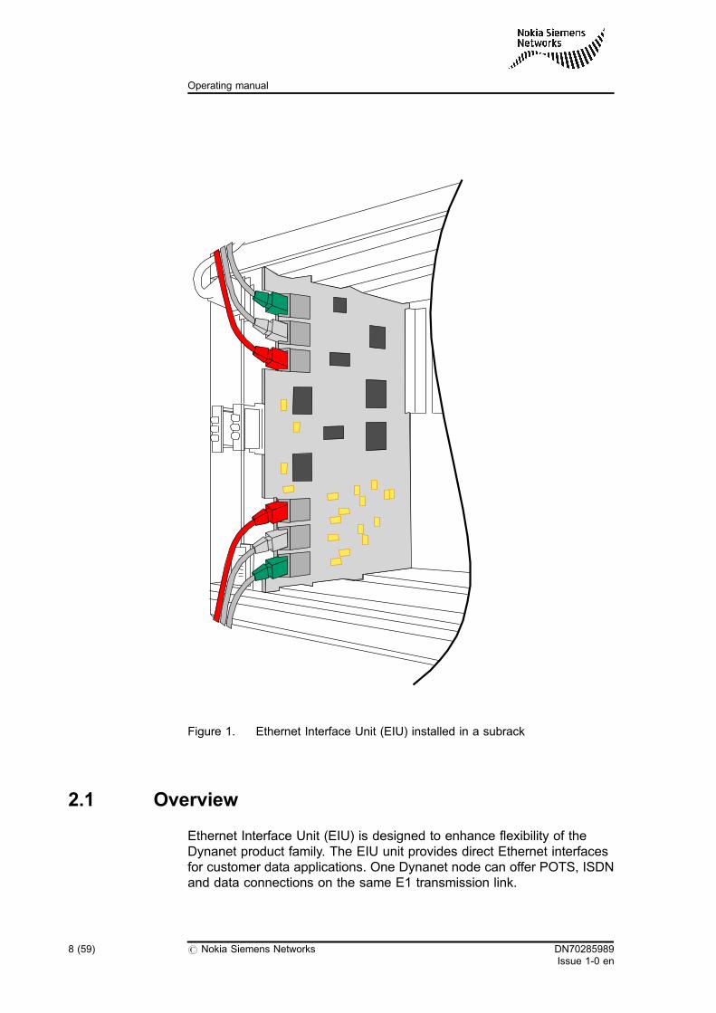
Figure 1. Ethernet Interface Unit (EIU) installed in a subrack
2.1 Overview
Ethernet Interface Unit (EIU) is designed to enhance flexibility of theDynanet product family. The EIU unit provides direct Ethernet interfacesfor customer data applications. One Dynanet node can offer POTS, ISDNand data connections on the same E1 transmission link.
8 (59) # Nokia Siemens Networks DN70285989Issue 1-0 en
Operating manual
The unit operates as a transparent bridge and it provides three plus threeindependent 10/100BASE-T Ethernet interfaces. EIU combines sixEthernet ports over the TDM netwok and all protocols are simply passedthrough from the LAN side to the TDM netwok. EIU can be connected toPCs, hubs and other LAN equipment by using the cabling with an RJ45connector. LAN interfaces can be individually configured to the 10BASE-Tor 100BASE-TX modes, full or half duplex. Ports can also be set to autonegotiation mode, and then best possible mode is automatically selected.All LAN ports have auto MDI/MDX capability to detect transmit and receivedirection. Hence cross-over cables are not needed.
The EIU has intergrated cable testing to analyse Ethernet cabling. Withthis function, the length of Ethernet cable can be measured and shortcircuits of cabling can be detected.
Ethernet packets are carried over the time-division multiplexing (TDM)network in the high-level data link control protocol (HDLC) frame. EIUoffers data rates n x 64 kbit/s (n=1...31) from 64 kbit/s up to 1984 kbit/sover a TDM link. EIU learns automatically medium access control (MAC)addresses on the LAN it is connected to and forwards only the frames thatare destined to another LAN. EIU can store up to 1024 MAC addresses.Maximum transfer unit is 1536 bytes and VLAN (IEEE802.1Q) taggedframes are forwarded transparently.
The unit is connected to the Dynanet bus and it can be installed into allDynanet cartridges and subracks. EIU needs a master unit which performsmultiplexing of data to the TDM network. As a master unit can operate DM2, DM 2+, DB 2, DN 2, or ACM2.
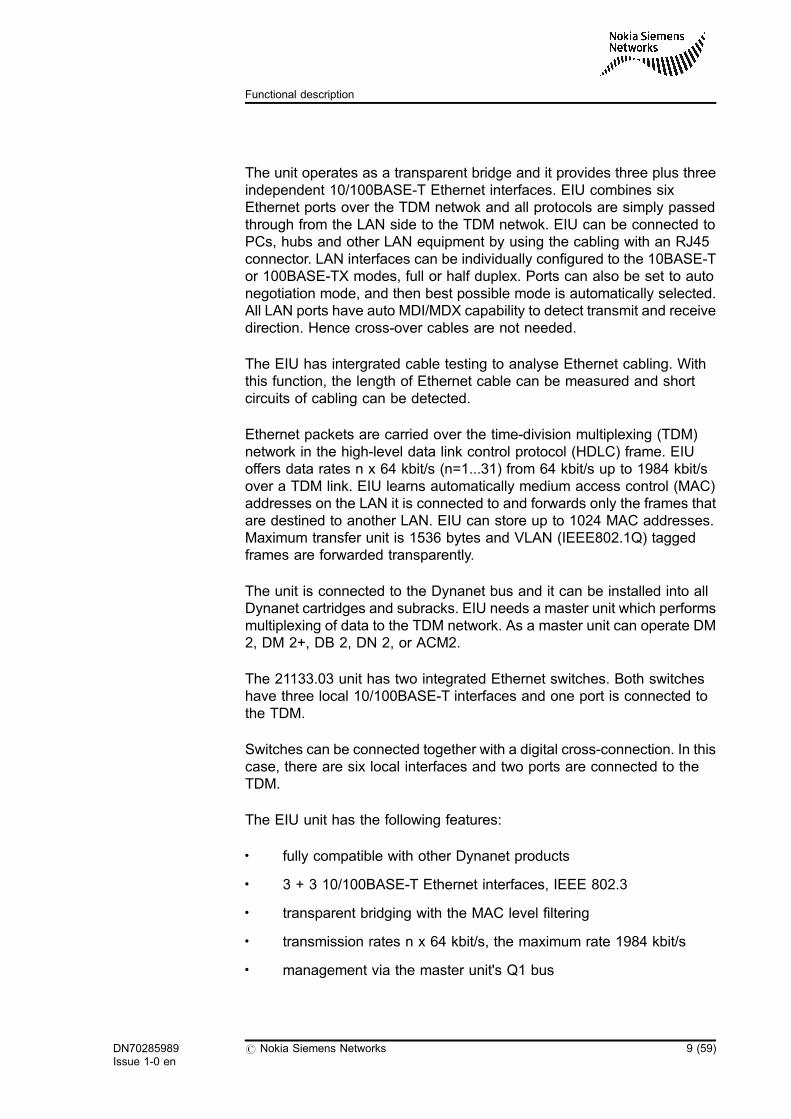
The 21133.03 unit has two integrated Ethernet switches. Both switcheshave three local 10/100BASE-T interfaces and one port is connected tothe TDM.
Switches can be connected together with a digital cross-connection. In thiscase, there are six local interfaces and two ports are connected to theTDM.
The EIU unit has the following features:
. fully compatible with other Dynanet products
. 3 + 3 10/100BASE-T Ethernet interfaces, IEEE 802.3
. transparent bridging with the MAC level filtering
. transmission rates n x 64 kbit/s, the maximum rate 1984 kbit/s
. management via the master unit's Q1 bus
DN70285989Issue 1-0 en
# Nokia Siemens Networks 9 (59)
Functional description
. Compatible with ET bridge adapter of DNT modem.
. two integrated Ethernet switches
. digital cross-connection.
. integrated cable testing
Figure 2. Block diagram
2.2 Network applications
This section shows some application examples how Dynanet nodes withEthernet Interface Units are often located in networks. EIU can beconnected to the whole LAN via external repeater hub, switch or router. Ordirectly up to six computers or other equipment with 10/100BASE-Tinterface.
10/100
10/100
10/100TDM
Q1
10/10010/100
10/100
DM2bus
Switch
Switch
LEDmodule
SDRAM
Bridge
SDRAM
Bridge
DIC
DIC
CPUSoftware
+5V+3,3V+2,5V+1,8V+1,5V VNB
VPB
10 (59) # Nokia Siemens Networks DN70285989Issue 1-0 en
Operating manual
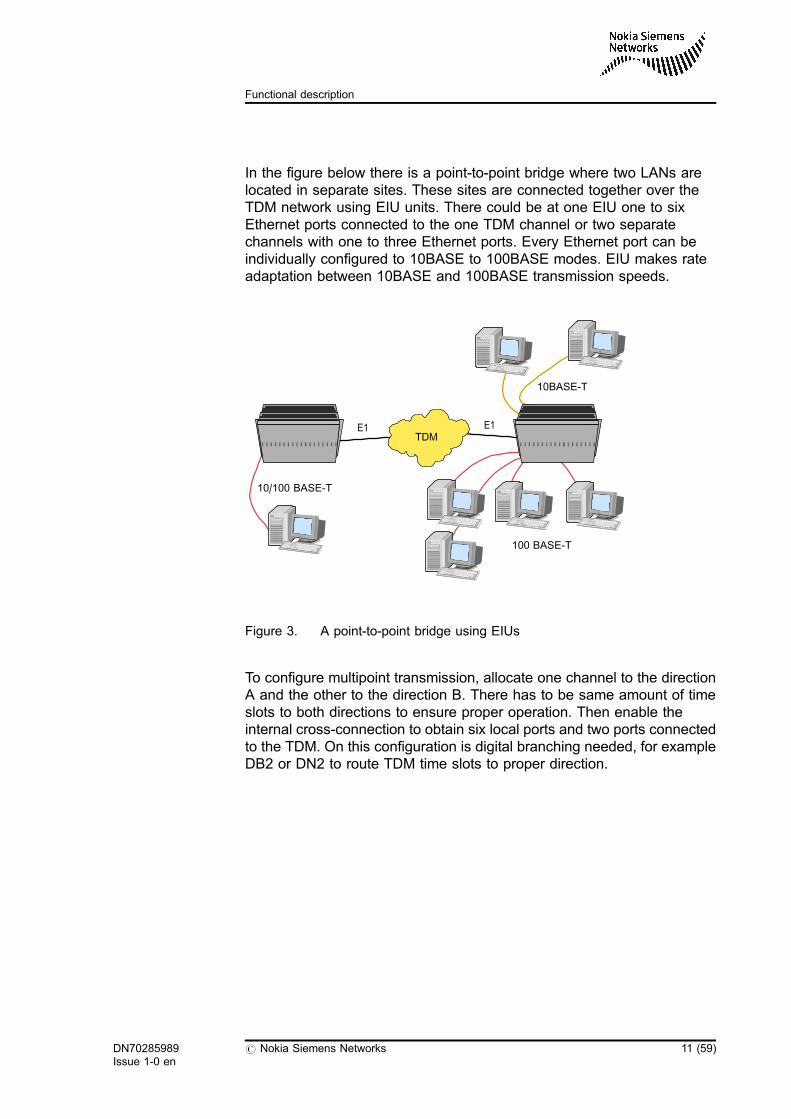
In the figure below there is a point-to-point bridge where two LANs arelocated in separate sites. These sites are connected together over theTDM network using EIU units. There could be at one EIU one to sixEthernet ports connected to the one TDM channel or two separatechannels with one to three Ethernet ports. Every Ethernet port can beindividually configured to 10BASE to 100BASE modes. EIU makes rateadaptation between 10BASE and 100BASE transmission speeds.
Figure 3. A point-to-point bridge using EIUs
To configure multipoint transmission, allocate one channel to the directionA and the other to the direction B. There has to be same amount of timeslots to both directions to ensure proper operation. Then enable theinternal cross-connection to obtain six local ports and two ports connectedto the TDM. On this configuration is digital branching needed, for exampleDB2 or DN2 to route TDM time slots to proper direction.
E1 E1
10BASE-T
10/100 BASE-T
100 BASE-T
TDM
DN70285989Issue 1-0 en
# Nokia Siemens Networks 11 (59)
Functional description
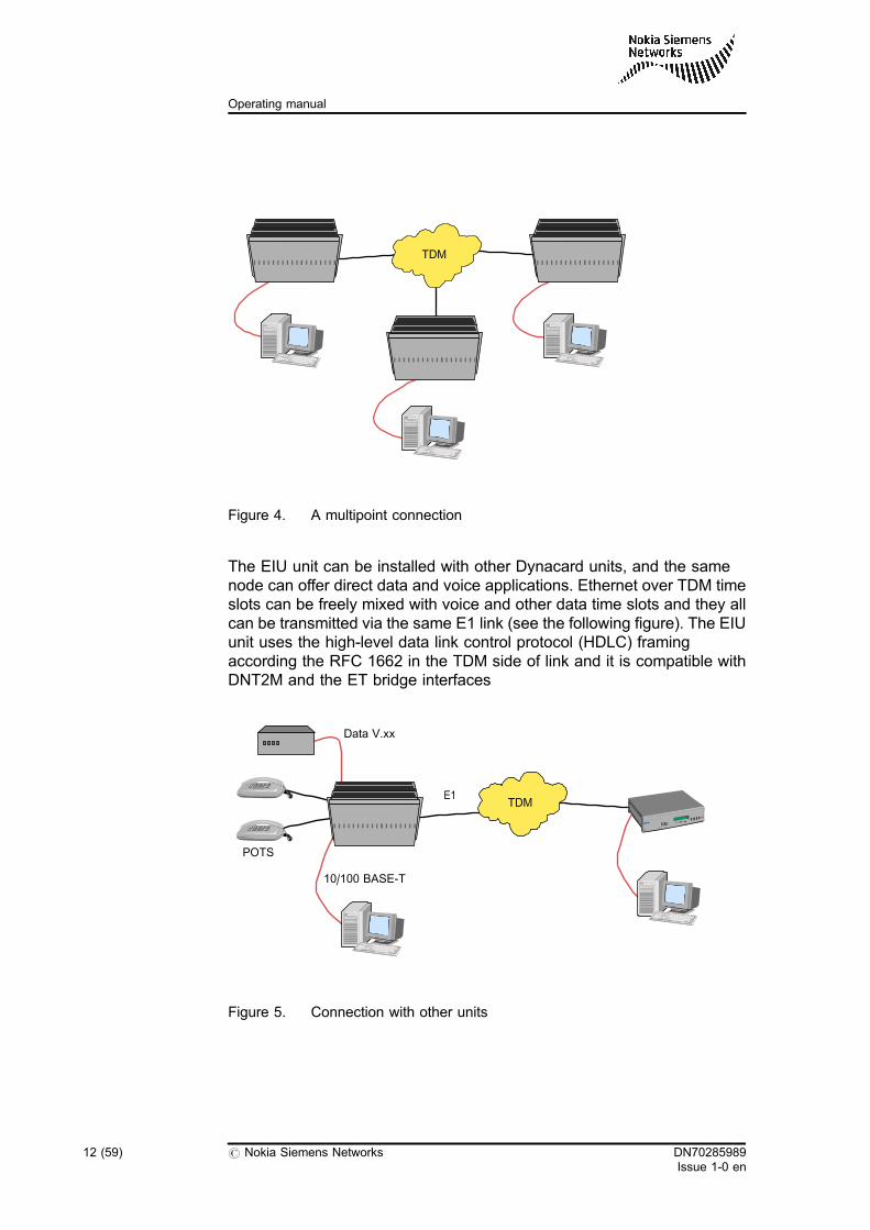
Figure 4. A multipoint connection
The EIU unit can be installed with other Dynacard units, and the samenode can offer direct data and voice applications. Ethernet over TDM timeslots can be freely mixed with voice and other data time slots and they allcan be transmitted via the same E1 link (see the following figure). The EIUunit uses the high-level data link control protocol (HDLC) framingaccording the RFC 1662 in the TDM side of link and it is compatible withDNT2M and the ET bridge interfaces
Figure 5. Connection with other units
TDM
E1
POTS
10/100 BASE-T
Data V.xx
TDM
12 (59) # Nokia Siemens Networks DN70285989Issue 1-0 en
Operating manual
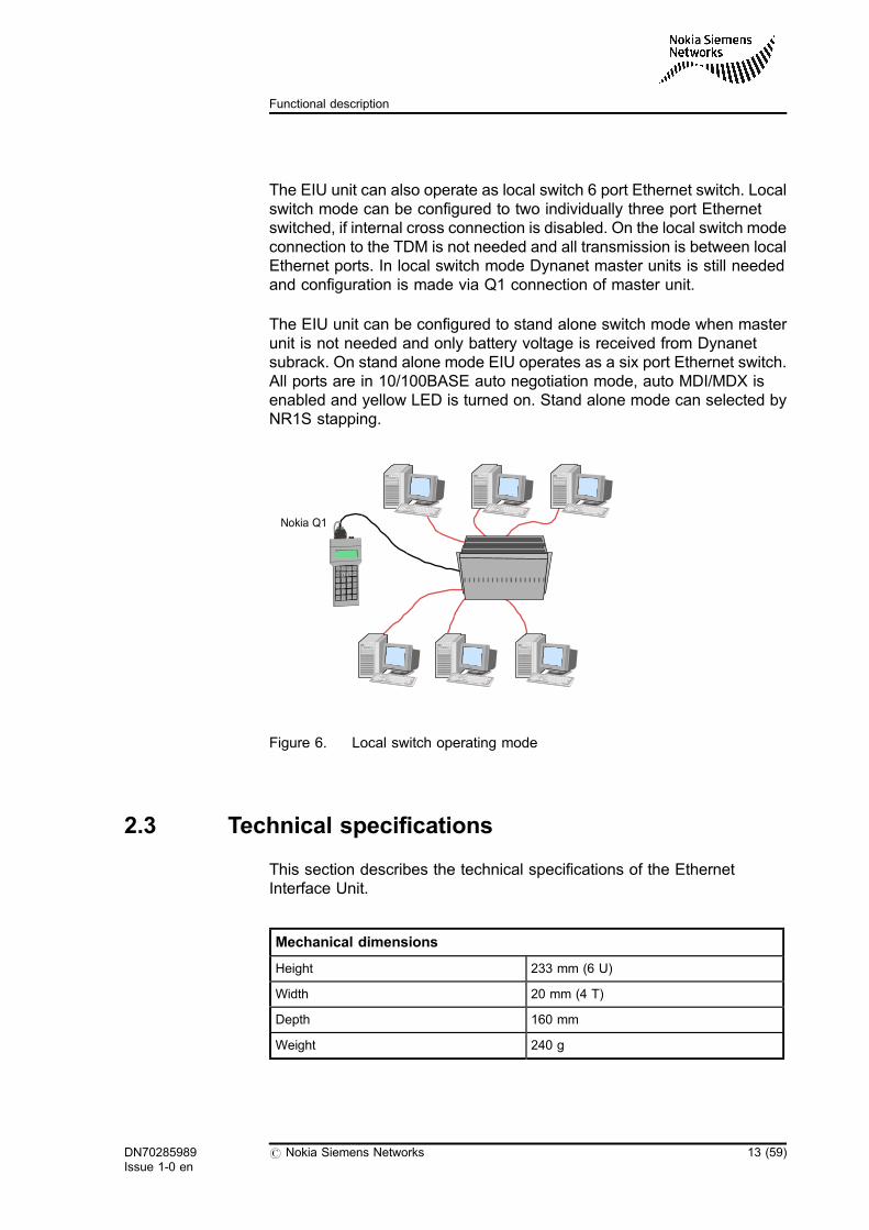
The EIU unit can also operate as local switch 6 port Ethernet switch. Localswitch mode can be configured to two individually three port Ethernetswitched, if internal cross connection is disabled. On the local switch modeconnection to the TDM is not needed and all transmission is between localEthernet ports. In local switch mode Dynanet master units is still neededand configuration is made via Q1 connection of master unit.
The EIU unit can be configured to stand alone switch mode when masterunit is not needed and only battery voltage is received from Dynanetsubrack. On stand alone mode EIU operates as a six port Ethernet switch.All ports are in 10/100BASE auto negotiation mode, auto MDI/MDX isenabled and yellow LED is turned on. Stand alone mode can selected byNR1S stapping.
Figure 6. Local switch operating mode
2.3 Technical specifications
This section describes the technical specifications of the EthernetInterface Unit.
Mechanical dimensions
Height 233 mm (6 U)
Width 20 mm (4 T)
Depth 160 mm
Weight 240 g
Nokia Q1
DN70285989Issue 1-0 en
# Nokia Siemens Networks 13 (59)
Functional description
Electrical specifications
Input voltage 20 V to 72 V
Power consumption
Typical 3.5 W
Maximum 10 W
Electromagnetic compatibility (EMC) ETS 300 386 (2005)
Interfaces
LAN 10BASE-T or 100BASE-TX Full duplex tohalf duplex Auto-negotiation Auto MDI/MDX
IEEE 802.3
Max. cable length 100 m
WAN HDLC, RFC 1662
Switch
MAC address table 1000 MAC addresses
Time out 5 minutes
MTU 1536 bytes
Cabling
Category 5 (CAT5)
Cable Shielded, type S/FTP
Max. cable length 100 m
Environmental conditions
Operation ETS 300 019, Class 3.1E. Temperaturecontrolled locations
Storage ETS 300 019, Class 1.2. Weatherprotected, not temperature controlledstorage locations
Transportation ETS 300 019, Class 2.3. Publictransportation
14 (59) # Nokia Siemens Networks DN70285989Issue 1-0 en
Operating manual
3 Installation
This chapter describes how to install the Ethernet Interface Unit into asubrack or subrack.
The covered topics are:
. Introduction
. Mounting of units into cartridges and subracks
. Signal interfaces and cabling
3.1 Introduction
The Ethernet Interface Unit is installed into a NDM equipment subrack.The NDM subrack product documentation explains the connection ofcentral battery voltages and rack alarms to the subracks, routing of signalcables, connection of groundings, as well as installation planning and workorder.
EIU units are ready to operate after their installation into a subrack and theconnection of signal cables.
Instructions for installation of the equipment into subracks and cabling ofsignal interfaces are given below.
Caution
Always use a wrist grounding or other such protection when handling aplug-in unit removed from its package.
DN70285989Issue 1-0 en
# Nokia Siemens Networks 15 (59)
Installation
3.2 Mounting units into cartridges and subracks
3.2.1 Power supply
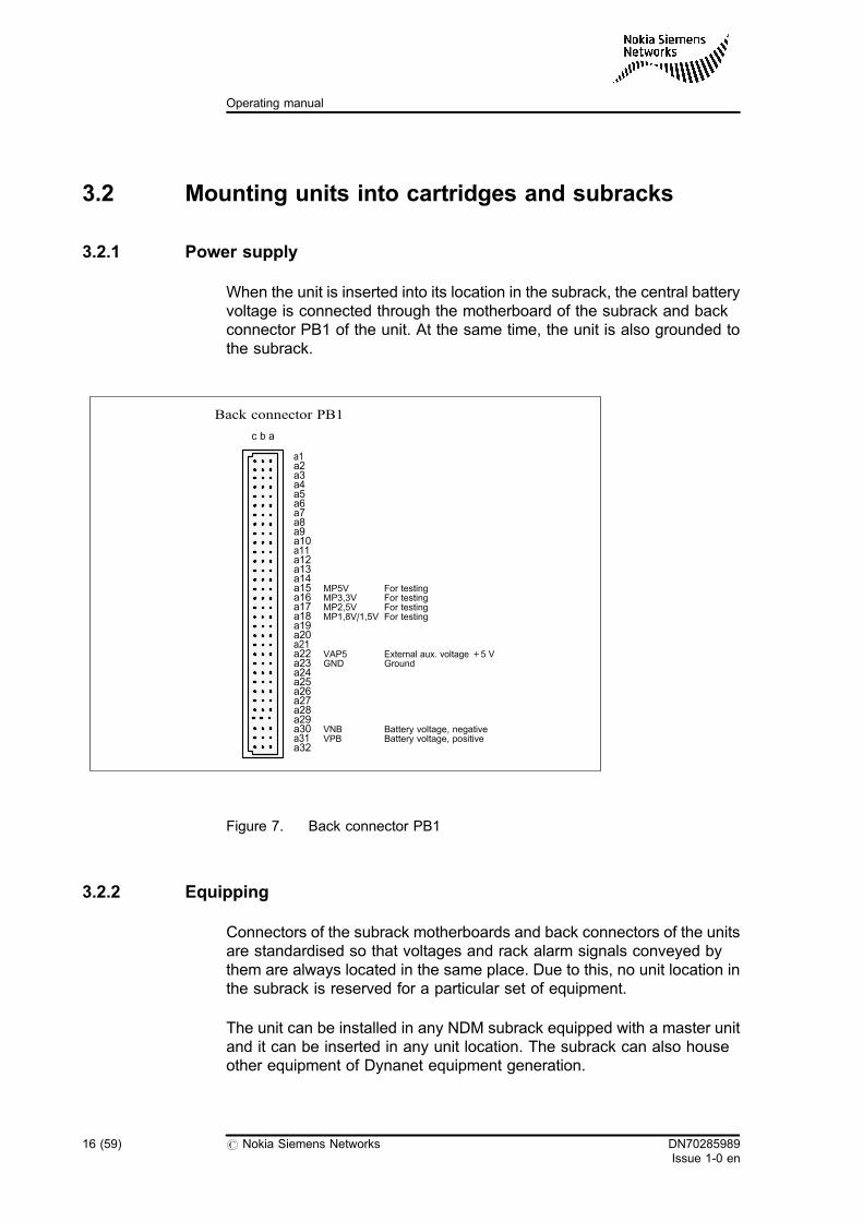
When the unit is inserted into its location in the subrack, the central batteryvoltage is connected through the motherboard of the subrack and backconnector PB1 of the unit. At the same time, the unit is also grounded tothe subrack.
Figure 7. Back connector PB1
3.2.2 Equipping
Connectors of the subrack motherboards and back connectors of the unitsare standardised so that voltages and rack alarm signals conveyed bythem are always located in the same place. Due to this, no unit location inthe subrack is reserved for a particular set of equipment.
The unit can be installed in any NDM subrack equipped with a master unitand it can be inserted in any unit location. The subrack can also houseother equipment of Dynanet equipment generation.
a1
c b a
a2a3a4a5a6a7a8a9a10a11a12a13a14
a20a21
a24a25a26a27a28a29
a32
Back connector PB1
a19
MP5VMP3,3VMP2,5VMP1,8V/1,5V
For testingFor testingFor testingFor testing
a15
a17a18
a16
a23
VNBVPB
Battery voltage, negativea30a31 Battery voltage, positive
VAP5 External aux. voltage +5 Va22GND Ground
16 (59) # Nokia Siemens Networks DN70285989Issue 1-0 en
Operating manual
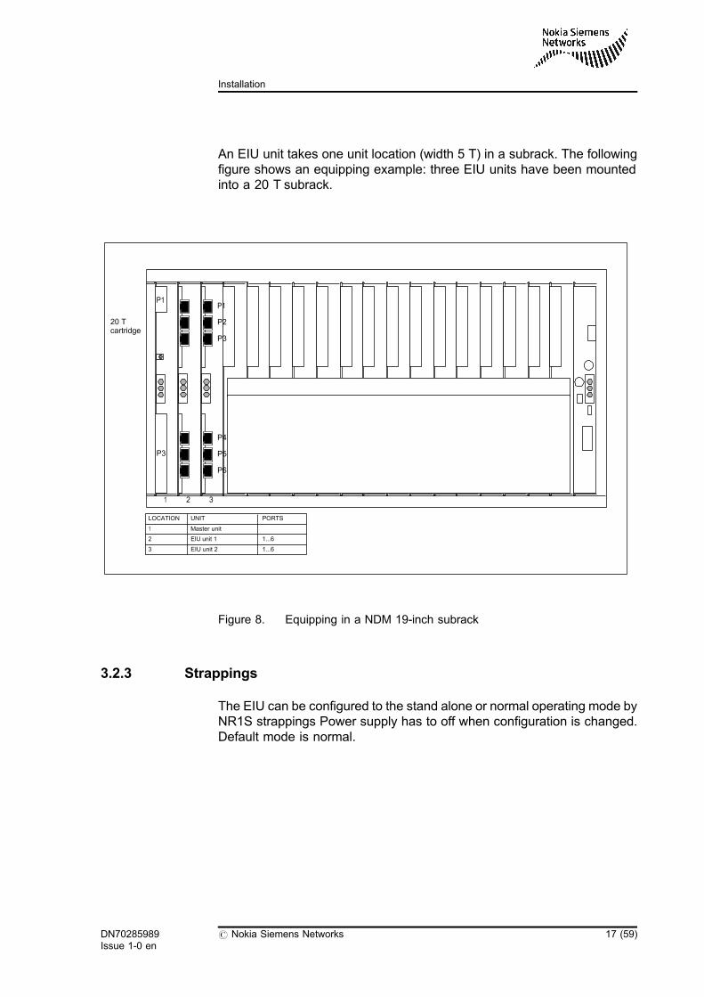
An EIU unit takes one unit location (width 5 T) in a subrack. The followingfigure shows an equipping example: three EIU units have been mountedinto a 20 T subrack.
Figure 8. Equipping in a NDM 19-inch subrack
3.2.3 Strappings
The EIU can be configured to the stand alone or normal operating mode byNR1S strappings Power supply has to off when configuration is changed.Default mode is normal.
1 2 3
P1
P3
20 Tcartridge
P1
P2
P3
P4
P5
P6
LOCATION UNIT
1
2
3
Master unit
EIU unit 1
EIU unit 2
1...6
1...6
PORTS
DN70285989Issue 1-0 en
# Nokia Siemens Networks 17 (59)
Installation
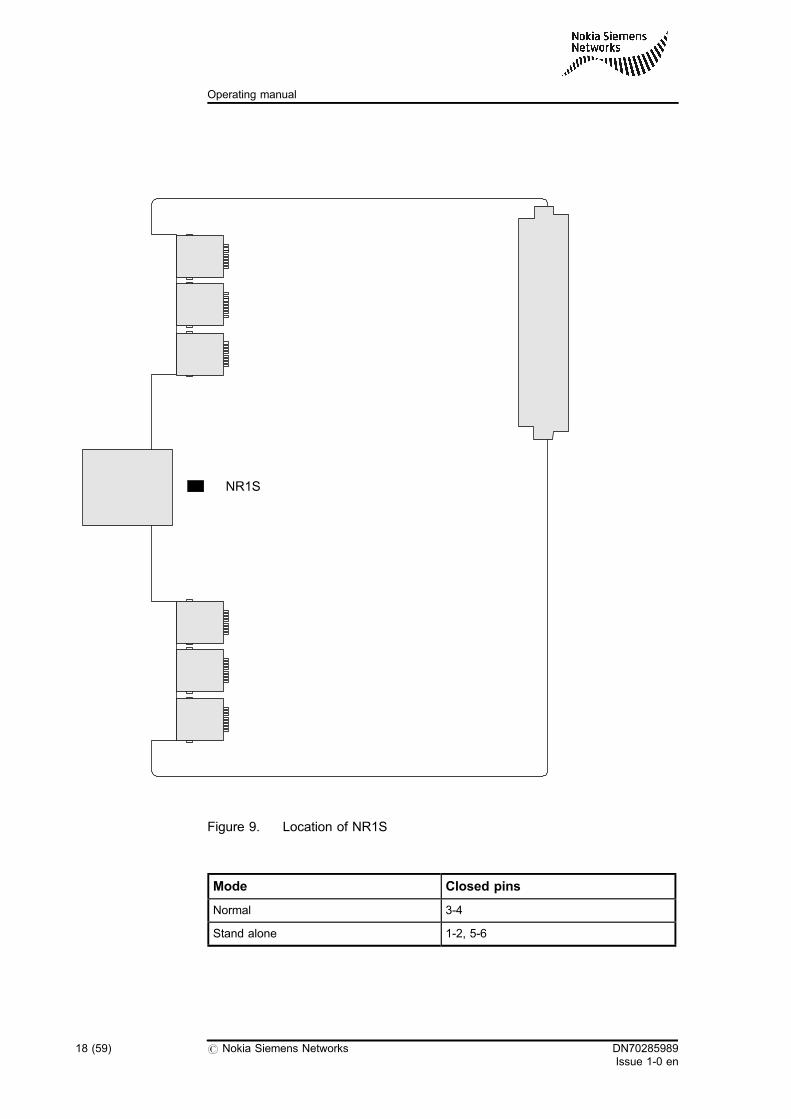
Figure 9. Location of NR1S
Mode Closed pins
Normal 3-4
Stand alone 1-2, 5-6
NR1S
18 (59) # Nokia Siemens Networks DN70285989Issue 1-0 en
Operating manual
3.3 Signal interfaces and cabling
The cable type is S/FTP Category 5 (CAT5) and the maximum cablelength is 100 m. Connectors are shielded 8-pin modular connectors (RJ45type).
Figure Pin order of the interface connectors on 21133.03 presents the pinorder of the interface connectors on the 21133.03 unit. Figure RJ45connector shows the RJ45 connector.
You can check correctness of the cabling at the link integrity LED.
Polarity of the RD- and RD+ signals is automatically corrected.
Auto MDI/MDX sets transmit and receive to correct pins of the RJ45connector. EIU can be connected to the network adapter and externetswitch or hub with the same cabling.
Normal mode Stand alone mode
DN70285989Issue 1-0 en
# Nokia Siemens Networks 19 (59)
Installation
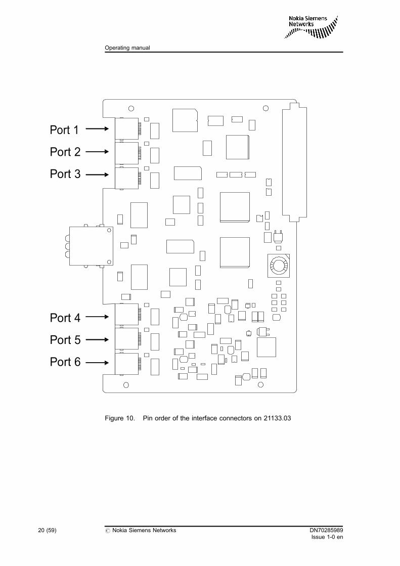
Figure 10. Pin order of the interface connectors on 21133.03
Port 1
Port 2
Port 3
Port 4
Port 5
Port 6
20 (59) # Nokia Siemens Networks DN70285989Issue 1-0 en
Operating manual
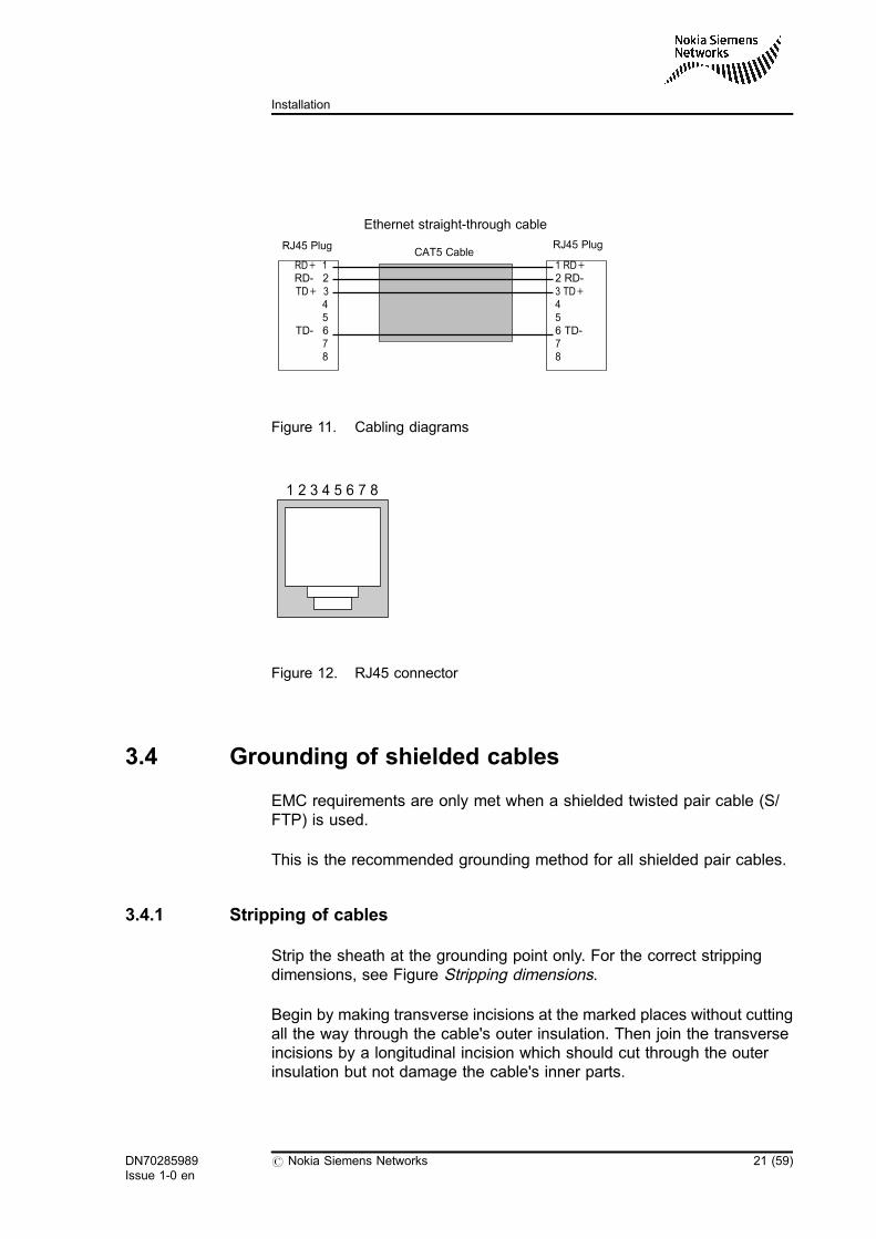
Figure 11. Cabling diagrams
Figure 12. RJ45 connector
3.4 Grounding of shielded cables
EMC requirements are only met when a shielded twisted pair cable (S/FTP) is used.
This is the recommended grounding method for all shielded pair cables.
3.4.1 Stripping of cables
Strip the sheath at the grounding point only. For the correct strippingdimensions, see Figure Stripping dimensions.
Begin by making transverse incisions at the marked places without cuttingall the way through the cable's outer insulation. Then join the transverseincisions by a longitudinal incision which should cut through the outerinsulation but not damage the cable's inner parts.
RD+ 1RD- 2TD+ 3
45
TD- 678
1 RD+2 RD-3 TD+456 TD-78
RJ45 Plug RJ45 PlugCAT5 Cable
Ethernet straight-through cable
1 2 3 4 5 6 7 8
DN70285989Issue 1-0 en
# Nokia Siemens Networks 21 (59)
Installation
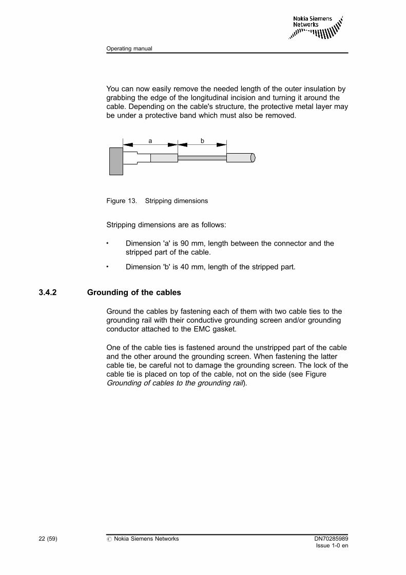
You can now easily remove the needed length of the outer insulation bygrabbing the edge of the longitudinal incision and turning it around thecable. Depending on the cable's structure, the protective metal layer maybe under a protective band which must also be removed.
Figure 13. Stripping dimensions
Stripping dimensions are as follows:
. Dimension 'a' is 90 mm, length between the connector and thestripped part of the cable.
. Dimension 'b' is 40 mm, length of the stripped part.
3.4.2 Grounding of the cables
Ground the cables by fastening each of them with two cable ties to thegrounding rail with their conductive grounding screen and/or groundingconductor attached to the EMC gasket.
One of the cable ties is fastened around the unstripped part of the cableand the other around the grounding screen. When fastening the lattercable tie, be careful not to damage the grounding screen. The lock of thecable tie is placed on top of the cable, not on the side (see FigureGrounding of cables to the grounding rail).
a b
22 (59) # Nokia Siemens Networks DN70285989Issue 1-0 en
Operating manual
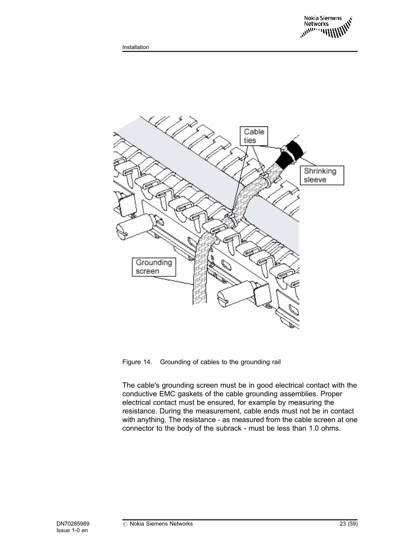
Figure 14. Grounding of cables to the grounding rail
The cable's grounding screen must be in good electrical contact with theconductive EMC gaskets of the cable grounding assemblies. Properelectrical contact must be ensured, for example by measuring theresistance. During the measurement, cable ends must not be in contactwith anything. The resistance - as measured from the cable screen at oneconnector to the body of the subrack - must be less than 1.0 ohms.
DN70285989Issue 1-0 en
# Nokia Siemens Networks 23 (59)
Installation

24 (59) # Nokia Siemens Networks DN70285989Issue 1-0 en
Operating manual
4 Operation
This chapter describes the operation and maintenance of the EthernetInterface Unit.
The covered topics are:
. Start-up of the unit
. Software settings
. Alarms
. Interface status LEDs
4.1 Introduction
4.1.1 General
Operation of the Ethernet Interface Unit is controlled via the serviceinterface of a master unit using the Service Terminal. Through thisinterface, equipment state and alarm data are read, controls and settingsare given, loopbacks are set, and so on.
If service interfaces have been connected into a bus and the buses havebeen further connected into a service network by means of a data channel,all equipment connected to the bus or network can be remote-controlledfrom one point using the Service Terminal or a network managementsystem.
Chapter Service Menu Reference describes the service menus obtainedfrom the equipment and their use. For the Service Terminal, there is aseparate Operating Manual.
DN70285989Issue 1-0 en
# Nokia Siemens Networks 25 (59)
Operation
The EIU unit is ready to operate after its installation into a subrackequipped with a master unit and connection of signal cables. Beforecommissioning, however, identifications and settings should be checked,required changes in the factory settings made, and statistics and errorcounters reset.
Commissioning measurements are not necessary.
4.1.2 Start-up of the unit
1. Insert the EIU unit, the master unit and any other units that may beincluded in the configuration in a Dynanet subrack.
2. Connect the Service Terminal to the service connector of the masterand establish a connection to the equipment (connection cables notconnected):
3. The green LED is lit to indicate that a connection from the ServiceTerminal to the equipment has been established.
Tip
Whenever a new plug-in unit is inserted in a unit location, it should beprovided with the default settings:
4. Perform equipment installation by installing all units:
Response:OBJ 7 RET
Current object:
AD 4095/DM2
9600 bit/s
/EOB/
TOP 6 9 u ,, , 1 RET, 1
26 (59) # Nokia Siemens Networks DN70285989Issue 1-0 en
Operating manual
Verify:
5. Check error messages given by the equipment:
If errors are found, check the configuration of the equipment.
4.1.3 Software settings
Set the following settings for both channels (the default setting with italic):
. Select transmission rate and time slot(s) for the channel
6,9,u,3,channel 2,1,transmission rate,1,time slot(s)
. Set the channel into use (channel in use/channel not in use
6,9,u,3,channel 1,1
Removing unit from the subrack
The unit must be provided with the following software settings when it isremoved from the subrack:
. Take the channels out of use by selecting:
6,9,u,3,n,1,2
- (duration approx. 10 s)
TOP 6 2 3 RET
Response:
Installing
/EOB/
, ,
TOP 6 2 0 RET
Response:
EIUnx64 unit 2/EOB/
, ,
TOP 1 RET
DN70285989Issue 1-0 en
# Nokia Siemens Networks 27 (59)
Operation
. Remove the unit from the configuration by selecting:
6,2,2,u
4.2 Maintenance
The equipment does not require scheduled maintenance. Maintenance isneeded only when the equipment indicates with alarms that there is a fault.Accurate data concerning the equipment state and nature of the fault areobtained via the Service Terminal.
Additional data on the condition of the equipment and on signal quality areobtained from measurements and statistics made by the equipment itself.Measurement results and statistics are read with the Service Terminal.
The Service Terminal can also be used to carry out tests and set onloopbacks possibly required in fault location.
4.2.1 Alarms
Figure 15. Alarm indication, general principle
RACK ALARM LEDS
RED Alarm A
WHITE
YELLOW
Alarm B
Alarm D
SERVICE LEDS
RED
YELLOW
GREEN
Serious fault in the equipment
Fault in the signal received bythe equipment, equipment fault,
Equipment connected to theService Terminal
or controlled service function(e.g. loopback) in the equipment
28 (59) # Nokia Siemens Networks DN70285989Issue 1-0 en
Operating manual
Interpretation of alarms at equipment level
When the red service LED is lit, there is a serious fault in the equipmentand the equipment usually has to be replaced with a new one. The redservice LED, red rack alarm lamp and programmable alarm output PA1 areactivated by means of an external auxiliary voltage.
When the yellow service LED is lit, the signal received by the equipmentmay be faulty. The alarm can also be triggered by a controlled servicefunction performed in the equipment (for example, loopback or forcedindication). The equipment indicating the alarm is not necessarily faulty;alternatively, the fault may be in the far-end equipment or in the signalcabling.
The green service LED is lit when the equipment is connected to theService Terminal.
Interpretation of alarms at unit level
Operation of the unit's logic section can be superficially checked byobserving the states of the unit's service LEDs.
. The red service LED is lit when the unit is faulty.
Tip
If there is a power supply fault, the red LED is lit even if the fault wereoutside the unit.
. The yellow LED is lit when the fault is somewhere else in theequipment.
. The green service LED is lit when transmission management actionsare directed to the unit via the service interface on the MUX unit.
State and fault messages
The following table describes the state and fault messages of theequipment that are obtained by the Service Terminal through the servicemenu option 1 Fault display. The rack alarm/service LED indication ineach situation is also indicated.
DN70285989Issue 1-0 en
# Nokia Siemens Networks 29 (59)
Operation
Table 1. Indication of fault conditions
Fault code(HEX.)
Fault condition Rack alarms LEDs
00H Power supply fault A red
14H Blocked from use A yellow
16H Loop to equipment B yellow
31H Loss of incomingsignal
B yellow
71H Buffer over/underflow
B yellow
80H Equipment fault A red
8EH Installation fault B red
95H Forced faultindication
B yellow/red/green
94H Equipment reset A red
8DH Forced control B yellow
4.2.2 Interface status LEDs
On the EIU unit, there are six bicolour red/green interface status LEDs,one for each interfaces. These LEDs indicate the operational state of theEthernet interface. LEDs are located under every RJ-45 connector.
. Integrity
The link integrity LED indicates a good link integrity on a twisted pairport. Link integrity informs that the EIU unit's port is connected toanother Ethernet-compatible equipment and the cabling isoperational. LED is green when port is 10BASE mode and red whenport is 100BASE mode.
. LAN activity
This LED is lit when the EIU unit's port is connected to anotherEthernet-compatible equipment and the cabling is operational. ThisLED blinks when data is received or transmitted thorough port..
. Buffer
This LED function is used to indicate a buffer overflow. The EIU unitremains functional even if buffer overflows occur.
30 (59) # Nokia Siemens Networks DN70285989Issue 1-0 en
Operating manual
The buffer LED function provides an indication to the systemmanager that the traffic rate is not balanced between the LAN andWAN sides and the buffer capacity is not sufficient for the currentset-up. If this situation continues for a while, the error LED will be litall the time. After the buffer has been cleared, the error LED will beturned off.
Buffer LEDs are located bottom side of EIU near LED holder.Channel 1 buffer LED is above LED holder and channel 2 buffer LEDis below LED holder.
Figure 16. Interface status LEDs on 21133.03
DN70285989Issue 1-0 en
# Nokia Siemens Networks 31 (59)
Operation

32 (59) # Nokia Siemens Networks DN70285989Issue 1-0 en
Operating manual
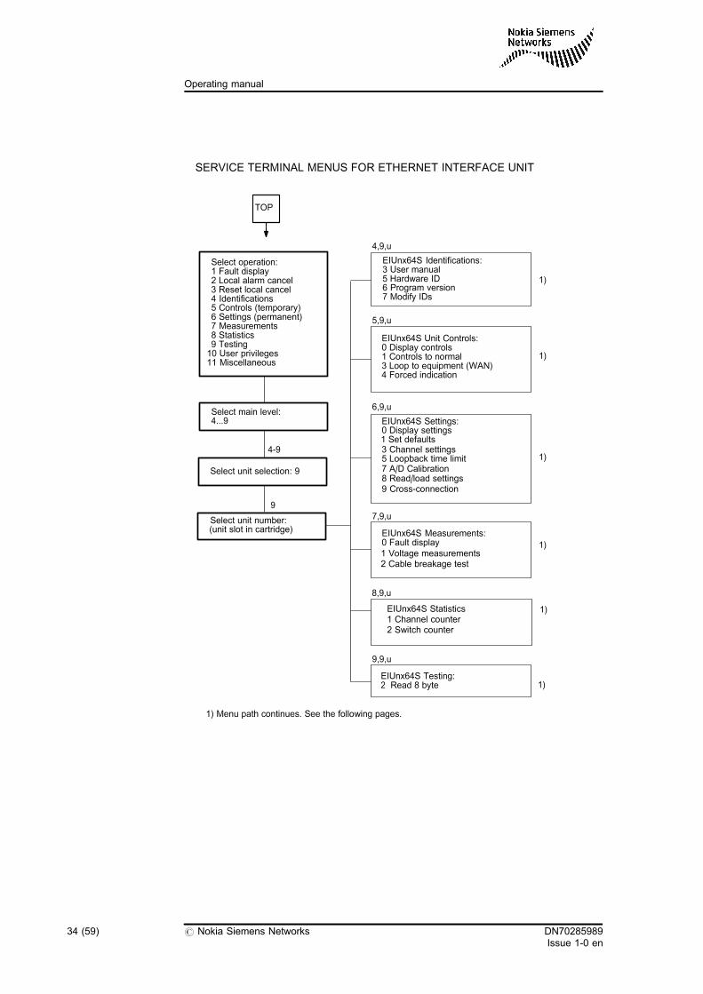
5 Service menu reference
This chapter shows the service menu diagrams of the EIU unit. Thediagrams consist of rectangular boxes (representing Service Terminaldisplays) which have been arranged in hierarchical fashion: the mainmenu is shown on the top left of the page and the submenus proceeddownwards and to the right of the main menu.
The following menus are covered:
. setting and reading identifications
. setting temporary controls
. setting and modifying permanent settings
. reading measurement results
. conducting tests.
5.1 Service menus
DN70285989Issue 1-0 en
# Nokia Siemens Networks 33 (59)
Service menu reference
2
1)
TOP
Select operation:1 Fault display2 Local alarm cancel3 Reset local cancel4 Identifications5 Controls (temporary)6 Settings (permanent)7 Measurements8 Statistics9 Testing10 User privileges11 Miscellaneous
SERVICE TERMINAL MENUS FOR ETHERNET INTERFACE UNIT
Select unit selection: 9
Select unit number:(unit slot in cartridge)
4-9
9
EIUnx64S Identifications:3 User manual5 Hardware ID6 Program version7 Modify IDs
EIUnx64S Unit Controls:0 Display controls1 Controls to normal
4 Forced indication
EIUnx64S Settings:0 Display settings1 Set defaults3 Channel settings5 Loopback time limit7 A/D Calibration
EIUnx64S Measurements:0 Fault display
EIUnx64S Testing:Read 8 byte
3 Loop to equipment (WAN)
4,9,u
5,9,u
6,9,u
7,9,u
9,9,u
Select main level:4...9
8 Read/load settings9 Cross-connection
1 Voltage measurements2 Cable breakage test
EIUnx64S Statistics1 Channel counter2 Switch counter
8,9,u
1)
1)
1)
1)
1)
1) Menu path continues. See the following pages.
34 (59) # Nokia Siemens Networks DN70285989Issue 1-0 en
Operating manual
4,9,u
C32385.20
21133.03 AO
25442.03 AO
Modify IDs:5 Hardware ID
Identification:0 Display1 Modify
Give new ID:1-15 characters
4,9,u,3
4,9,u,5
4,9,u,6
4,9,u,7 4,9,u,7,5
4,9,u,7,5,1
IDENTIFICATIONS:
EIUnx64S Identifications:3 User manual5 Hardware ID6 Program version7 Modify IDs
5,9,u
Sel. chan.:
Select indicator:
5,9,u,3
5,9,u,4
Loop to equipment (WAN):1 Display loop state2 Set loop on3 Remove loop
CONTROLS:
1 or 2
1 Red2 Yellow
3 Green
Set indicator state:
0 Display state1 Set forced state
2*Set nonforced state
Set forced state:1 On2 Off
5,9,u,4,1-3
5,9,u,4,1-3,1
5,9,u,3,1-2
EIUnx64S Unit Controls:0 Display controls1 Controls to normal
4 Forced indication3 Loop to equipment (WAN)
DN70285989Issue 1-0 en
# Nokia Siemens Networks 35 (59)
Service menu reference
EIUnx64S Settings:0 Display settings
3 Channel settings5 Loopback time limit7 A/D Calibration
Sel. chan.:1 or 2
Display EIU Settings:1 All unit settings2 Channel settings3 Common settings
SETTINGS:
Give measured supplyvoltage without sign:(4000...6000 mV)
Set limit:
6,9,u
1 Set defaults
8 Read/load settings
6,9,u,0
6,9,u,3
6,9,u,5
6,9,u,7
6,9,u,0,2
6,9,u,5,1
6,9,u,7,2
1...254 minutes255 = No time limit
6,9,u,1
Are you sure?99 Set defaults
6,9,u,8
Read/load Settings:0 Display setup ID1 Read from Unit2,* Load to Unit
(* = <DATA>)
Loopback time limit:0 Display limitSet limit1
Select voltage:2 + 5 V
Sel. chan.:1 or 2
1) Menu path continues.See the following pages.
9 Cross-connection
6,9,u,9
Cross-connection:0 Display1 Enable2 * Disable
36 (59) # Nokia Siemens Networks DN70285989Issue 1-0 en
Operating manual
Time slot selection:
Select channel:1 or 2
6,9,u
Channel state:0 DisplayChannel in useChannel not in use
12*
Rate and time slot selection:0 DisplaySet rate and time slots1
6,9,u,3,n,1
6,9,u,3,n,2
6,9,u,3,n,3
6,9,u,3,n,4
6,9,u,3,n,5
Select rate:1...31 (*64kbit/s)
6,9,u,3,n,2,16,9,u,3
CHANNEL SETTINGS:
6,9,u,3,n
EIUnx64S Channel settings:1 Channel stateRate and time slotsLAN interface modePort stateCable settingsLoss of incoming signal
234567 WAN idle signal
2 Remove time slots
1 Manual selectionAutom. selection2
6,9,u,3,n,2,1,n
EIUnx64S Settings:
0 Display settings1 Set defaults3 Channel settings5 loopback time limit7 A/D Calibration
6,9,u,3,n,2,1,n,1
6,9,u,3,n,2,1,n,2
8 Read/load settings9 Cross connection
Give time slot:1...31
Give starting time slot:1...31
Loss of incoming signal:0 Display state1 Enable alarm2* Disable alarm
6,9,u,3,n,6
6,9,u,3,n,6,1-2
6,9,u,3,n,7
WAN idle signal0 Display1* 011111102 11111111
LAN mode:
99 All1 Port 12 Port 23 Port 3
Select port
99 All1 Port 12 Port 23 Port 3
Select port
99 All1 Port 12 Port 23 Port 3
Select port
0 Display1 10M Fdx2 10M Hdx3 100M Fdx4 100M Hdx5 *Auto negotiation
6,9,u,3,n,3,0-3
99 All1 Port 12 Port 23 Port 3
Select port Port settings0 Display1 Set ON2 Set OFF
6,9,u,3,n,4,0-3
Cable Settings0 Display1 MDI/MDX Crossover
6,9,u,3,n,5,0-3
MDI/MDX Crossover1 Auto Crosover2 Crossed3 Normal
6,9,u,3,n,5,0-4,1
DN70285989Issue 1-0 en
# Nokia Siemens Networks 37 (59)
Service menu reference
5.2 General
The EIU unit is controlled with the Service Terminal or TransmissionManagement System TMS (see the corresponding operating manuals).The Service Terminal or TMS can be used for performing basic settings ofthe equipment and storing them into a non-volatile storage (replacesjumper settings), performing maintenance-related functions, for exampleloopbacks, and reading identifications, statistics and other informationfrom the equipment.
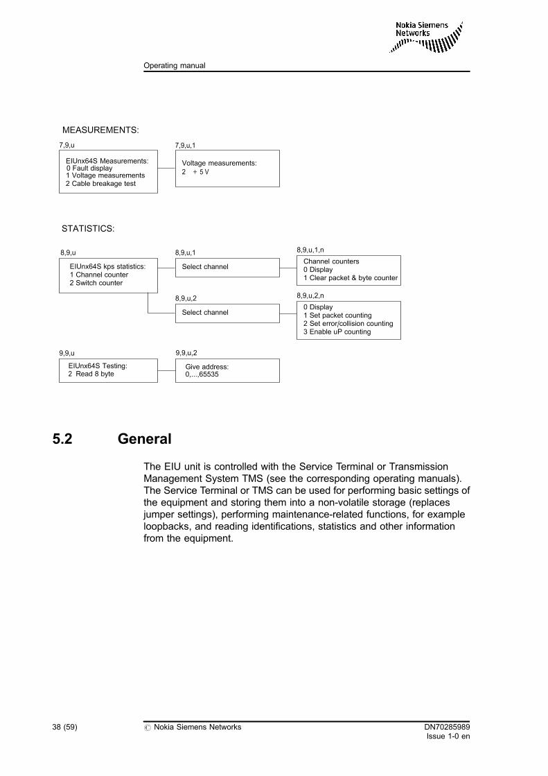
MEASUREMENTS:
EIUnx64S Measurements:
1 Voltage measurements2 Cable breakage test
EIUnx64S Testing:Read 8 byte
Give address:0,...,65535
Voltage measurements:2 + 5 V
2
7,9,u 7,9,u,1
0 Fault display
9,9,u
STATISTICS:
EIUnx64S kps statistics:1 Channel counter2 Switch counter
8,9,u
9,9,u,2
Select channel
8,9,u,1Channel counters0 Display1 Clear packet & byte counter
8,9,u,1,n
Select channel
8,9,u,20 Display1 Set packet counting2 Set error/collision counting3 Enable uP counting
8,9,u,2,n
38 (59) # Nokia Siemens Networks DN70285989Issue 1-0 en
Operating manual
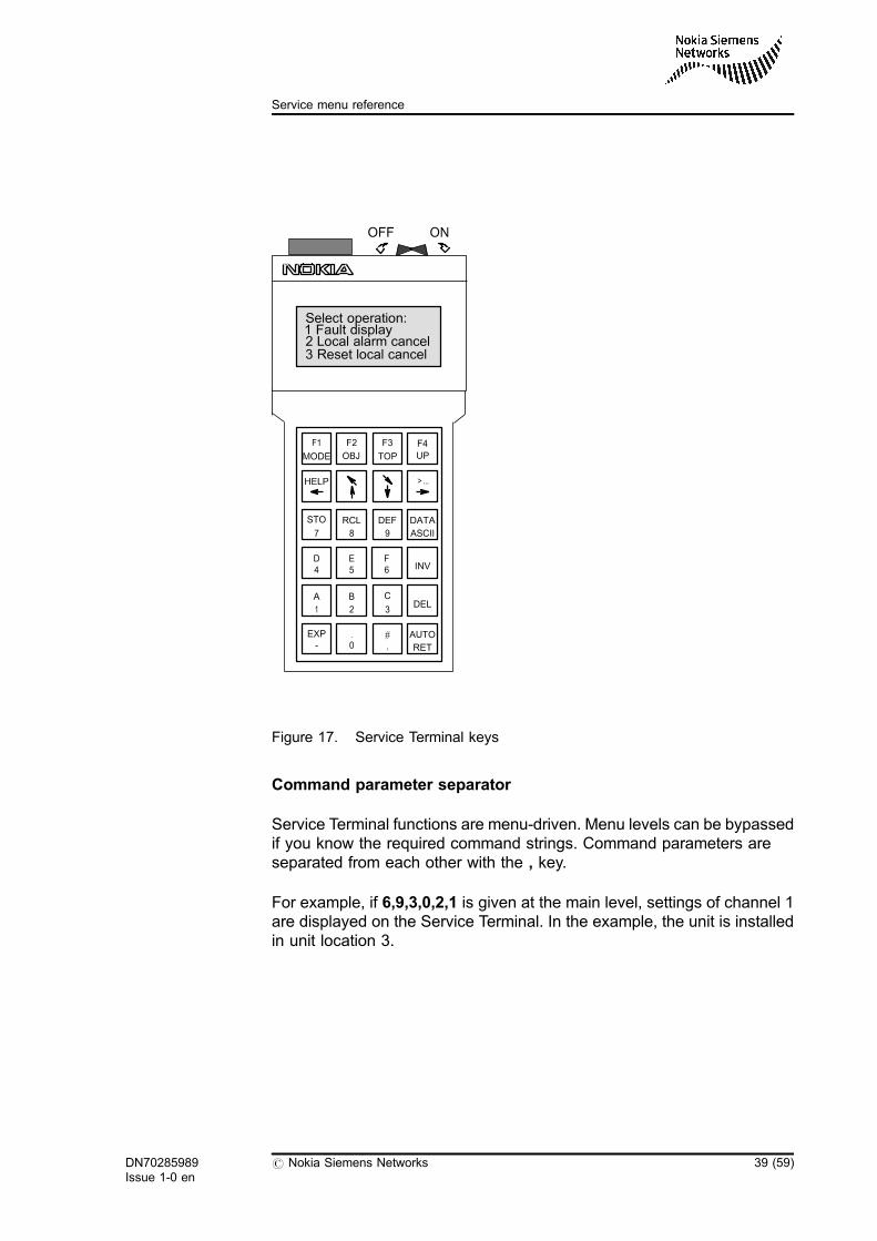
Figure 17. Service Terminal keys
Command parameter separator
Service Terminal functions are menu-driven. Menu levels can be bypassedif you know the required command strings. Command parameters areseparated from each other with the , key.
For example, if 6,9,3,0,2,1 is given at the main level, settings of channel 1are displayed on the Service Terminal. In the example, the unit is installedin unit location 3.
ONOFF
Select operation:1 Fault display2 Local alarm cancel3 Reset local cancel
DATA
AUTO
F1
MODE
F2
OBJ
F3
TOP UP
HELP >...
STO RCL DEF
D E FINV
A B CDEL
EXP . #
RET,0-
7 8 9 ASCII
4 5 6
1 2 3
F4
DN70285989Issue 1-0 en
# Nokia Siemens Networks 39 (59)
Service menu reference
5.3 Service Terminal main menu
When the Service Terminal is switched on, it shifts into the Use ofequipment/Select operation mode, which is the factory setting. The mainmenu common to all equipment, offered by the Service Terminal, isdisplayed:
Select operation:
1 Fault display
2 Local alarm cancel
3 Reset local cancel
4 Identifications
5 Controls (temporary)
6 Settings (permanent)
7 Measurements
8 Statistics
9 Testing
10 User privileges
11 Miscellaneous
1 Fault display
The fault display indicates the fault situation of the equipment. Theinformation contained in the fault data includes:
. equipment ID (for example, DM 2 ABC)
. fault category (A, B, D, S or combination of these)
. control block indicating the fault
. fault type.
You can set the equipment ID in the Identifications menu. The faultdisplay is not related just to one unit, it concerns the entire equipment.
2 Local alarm cancel
In a fault situation, the Local alarm cancel option cancels rack alarms Aand B. As a reminder of cancelling, a D-alarm is given. Cancelling withouta fault situation produces a B-alarm. The Local alarm cancel optionconcerns the entire equipment.
40 (59) # Nokia Siemens Networks DN70285989Issue 1-0 en
Operating manual
3 Reset local cancel
The normal situation is restored in the equipment.
4 Identifications
Under this function, you can read the equipment identifying data, such asthe equipment type, name given to it and the type and version of theprogram used. You can modify some of these identifications.
5 Controls (temporary)
Under this function, you can give controls that temporarily change theoperating mode of the equipment. Such controls are, for example,interface loopbacks.
6 Settings (permanent)
Settings determine the operating mode of the equipment. They areretained in the equipment storage also during a power outage.
7 Measurements
This function allows you to make various measurements, which theequipment performs itself, for example voltage measurements.
8 Statistics
This function allows you to read statistics about Ethernet transmission, forexample the amount of transmitted frames
9 Testing
Automatic tests performed by the equipment itself.
10 User privileges
There are no user privileges functions in use in this unit.
11 Miscellaneous
There are no miscellaneous functions in use in this unit.
DN70285989Issue 1-0 en
# Nokia Siemens Networks 41 (59)
Service menu reference

Access to unit
Since the EIU unit is not provided with a service interface of its own,service functions must be directed to the EIU unit via the master unit. First,select the main level menu (4...9), then 9 followed by a comma, and finallythe unit number: 4...9,9,unit. Unit numbering starts from 1 on the left. Nowthe menu of the unit concerned, below the main level, is displayed.
5.4 Ethernet Interface Unit menus
The EIU unit is controlled via the service interface in the master unit. Themain unit provides the menus related to the common section of theequipment, and via the menus offered by it, you can select a particular unitas an object. The EIU unit provides the menus required for its control.
5.4.1 Fault display
The main unit collects fault data from other units into a common faultstorage. At the initialisation stage, the main unit collects from each unit thefault-related data: faults that are active in the unit, their effect on alarmoutputs, the fault code related to each fault, the way the fault is indicated(colour of the indicator), and the name of the control block.
The main unit generates a response to the fault inquiry. This responsecontains the following information:
. equipment ID (equipment name)
. fault status
. fault data. faulty object. fault type (fault code).
Example: *02A (ABS)
MUX-2M unit 1:
. incoming 2M missing
nx64k unit 3:
. power supply fault
42 (59) # Nokia Siemens Networks DN70285989Issue 1-0 en
Operating manual
The equipment, named 02A, has alarms A, B and S active. Faultmessages come from the equipment interface 1 control block (unit 1), thefault being that the incoming 2 Mbit/s signal is missing, and from thecontrol block of the nx64k EIU unit (unit 3), the fault being a power supplyfault.
The nx64k EIU unit contains one control block and equipment interface.
Faults controlled in the EIU unit
. Power supply fault
. Forced indication
. Equipment fault
. Equipment reset
. Loop to equipment
. Buffer overflow (2 Mbit/s transmit and receiving clocks are notsynchronised)
. Installation fault
. Loss of incoming signal (Link integrity fault, Ethernent link is missing)
. Blocked from use
. Forced control (Switch in standalone mode).
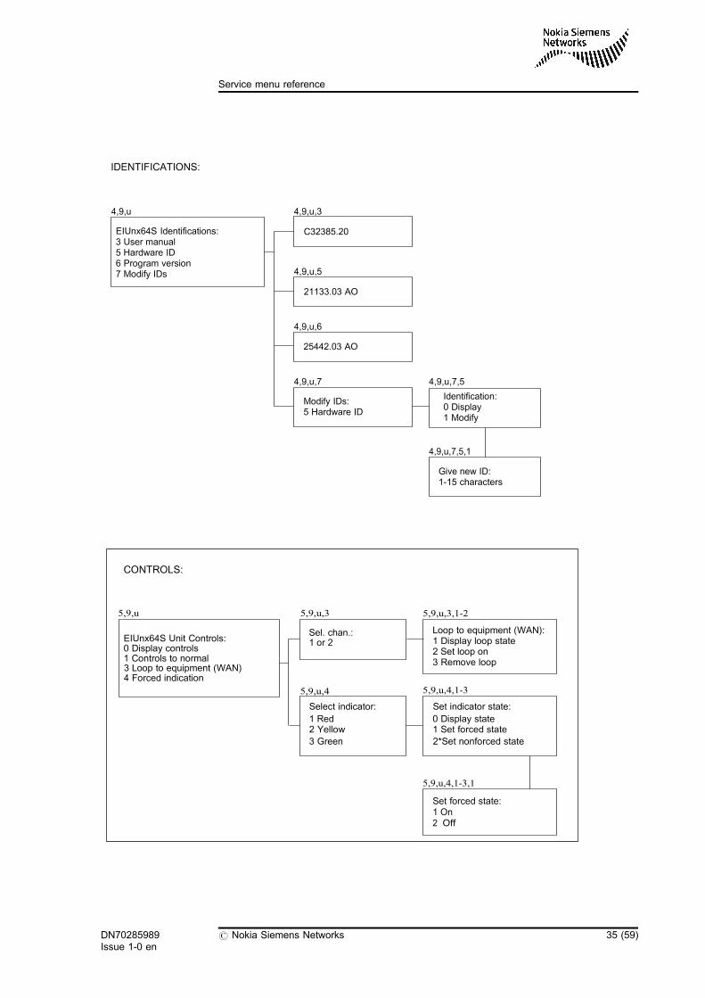
5.4.2 Identifications
4,9,u EIU nx64k Identifications
EIU nx64k Identifications:
3 User manual
5 Hardware ID
6 Program version
7 Modify IDs
In the menu, options 3, 5 and 6 display the equipment identifications.Option 7 allows you to modify the ID under option 5.
4,9,u,3 User manual
This menu item displays the sales item of the EIU unit's Operating manual.The response is fixed. An example:
DN70285989Issue 1-0 en
# Nokia Siemens Networks 43 (59)
Service menu reference
C33990.20
4,9,u,5 Hardware ID
Unit type designation and version designation. Set at the factory, but youcan change it, for example, in connection with a repair. A responseexample:
21133.03 A1
4,9,u,6 Program version
Program type and version; fixed. A response example:
25442.03 A1
4,9,u,7 Modify IDs
Modify IDs:
5 Hardware ID
Option 5 displays the menu:
Identification:
0 Display
1 Modify
Option 0 displays the type designation and version, and option 1 producesa prompt:
Give new ID:
1-15 characters
When you use the Service Terminal, you must give the letters contained inthe new type designation in the ASCII format. For example, you can obtainthe letter T by selecting:
44 (59) # Nokia Siemens Networks DN70285989Issue 1-0 en
Operating manual
5.4.3 Controls (temporary)
5,9,u EIU nx64k Unit Controls
EIU nx64k Unit Controls:
0 Display controls
1 Controls to normal
3 Loop to equipment (WAN)
4 Forced indication
5,9,u,0 Display controls
This option displays all the controls set on in the unit. A response example:
On chan :1
Loop to equipment (WAN)
On chan :2
No loop
Red indicator is in forced on state
5,9,u,1 Controls to normal
Forces all EIU unit controls to normal state (cancels loops and forcedcontrols of the indicators).
5,9,u,3 Loop to equipment (WAN)
In an equipment loopback, the output signal of the equipment is connectedback to the WAN before line buffers. All time slots of the selected channelare looped as they are. This loop can only be used when a 2048 Mbit/stelecom analyser is connected to the master unit. The actual Ethernettransmission can not be looped back.
This options displays the following menu:
5 4 ASCII
DN70285989Issue 1-0 en
# Nokia Siemens Networks 45 (59)
Service menu reference
Sel. chan.:
1 or 2
Both selections display the menu:
Loop to equipment (WAN)
0 Display loop state
1 Set loop on
2 Remove loop
Option 0 displays the state of the loopback on the channel. A responseexample:
Channel 1: Loop to MUX on
By option 1, you can set the selected loop on for the selected channel.Selection of the option causes a B-alarm and a fault message about theloopback to be given to the master unit. If you set an equipment loopbackon, transmission to the Ethernet port is cut.
Option2 allows you to cancel the selected loopback from the selectedchannel.
5,9,u,4 Forced indication
Select indicator:
1 Red
2 Yellow
3 Green
All options display the following menu:
Set indicator state:
0 Display state
1 Set forced state
2*Set nonforced state
Option 0 displays the state of the forced control of the selected indicator. Aresponse example:
46 (59) # Nokia Siemens Networks DN70285989Issue 1-0 en
Operating manual
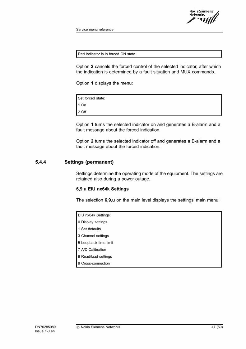
Red indicator is in forced ON state
Option 2 cancels the forced control of the selected indicator, after whichthe indication is determined by a fault situation and MUX commands.
Option 1 displays the menu:
Set forced state:
1 On
2 Off
Option 1 turns the selected indicator on and generates a B-alarm and afault message about the forced indication.
Option 2 turns the selected indicator off and generates a B-alarm and afault message about the forced indication.
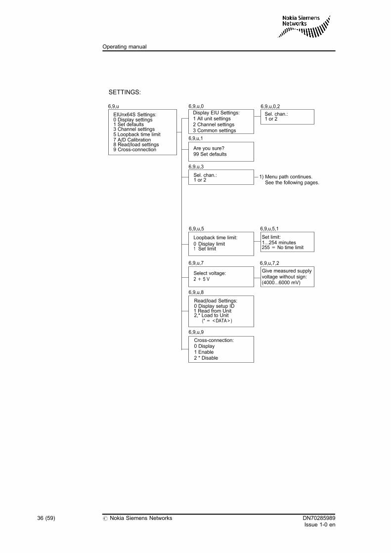
5.4.4 Settings (permanent)
Settings determine the operating mode of the equipment. The settings areretained also during a power outage.
6,9,u EIU nx64k Settings
The selection 6,9,u on the main level displays the settings' main menu:
EIU nx64k Settings:
0 Display settings
1 Set defaults
3 Channel settings
5 Loopback time limit
7 A/D Calibration
8 Read/load settings
9 Cross-connection
DN70285989Issue 1-0 en
# Nokia Siemens Networks 47 (59)
Service menu reference
6,9,u,0 Display settings
Display EIU settings:
1 All unit settings
2 Channel settings
3 Common settings
Option 1 displays the channel states and the time slots allocated for them.
Option 2 displays the menu:
Sel. chan.:
1 or 2
The state of the selected channel, as well as the transmission rate and thetime slots allocated are displayed.
Option 3 displays the slip alarm limits of the receive and transmit buffersand the time limits of the test and measurement loopback.
6,9,u,1 Set defaults
The program responds by displaying a new menu:
Are you sure?
99 Set defaults
The default settings are:
Loopback time limit 5 minutes
Transmission rate to the TDM 1 x 64 kbit/s
Time slot 1 on channel 1
2 on channel 2
LAN interface mode Auto negotiation
Loss of incoming signal alarm Disabled
Cross-connection Disabled
WAN idle signal 01111110
MDI/MDX crossover Auto
Ethernet port states On
48 (59) # Nokia Siemens Networks DN70285989Issue 1-0 en
Operating manual
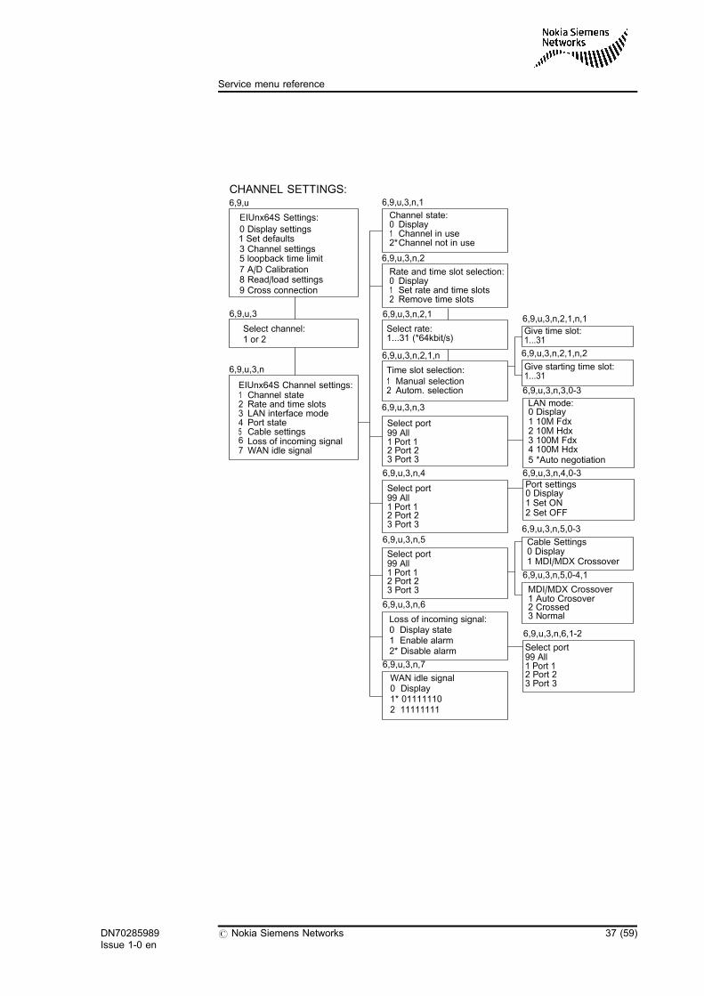
6,9,u,3 Channel settings
Sel. chan.: 1 or 2
Both selections display the following menu:
EIU nx64k Channel Settings:
0 Display settings
1 Channel state ON/OFF
2 Rate and time slots
3 LAN mode
4 Port state
5 Cable settings
6 Loss of incoming signal
8 WAN idle signal
6,9,u,3,n,1 Channel state
Channel state:
0 Display
1 Channel in use
2*Channel not in use
Option 0 displays the channel state.
By option 1, you can request the master unit to set the time slots allocatedfor the channel into use. If any of the requested time slots is already in use,the command is not executed and a message on overlapping time slots issent back to the Service Terminal.
Option 2 allows you to request the master unit to take out of use the timeslots used currently on the channel.
DN70285989Issue 1-0 en
# Nokia Siemens Networks 49 (59)
Service menu reference
6,9,u,3,n,2 Rate and time slots
Rate and time slot selection:
0 Display
1 Set rate and time slots
2 Remove time slots
Option 0 displays the time slots allocated and the transmission rate for theWAN channel.
Option 1 displays the menu:
Select rate:
1...31 (*64 kbit/s)
Selected transmission rate is the rate for the WAN side link. Transmissionrate is n x 64 kbit/s and there must be n pcs free time slots.
After the transmission rate has been entered, the following menu isdisplayed:
Time slot selection:
1 Manual selection
2 Autom. selection
When the Manual selection option is chosen, the following menu isdisplayed:
Give time slot:
1...31
Time slots are entered in this menu. Time slot 0 and the time slots alreadyallocated for other channels cannot be entered. The time slots allocatedearlier for the channel in question are automatically deallocated.
When the Autom. selection option is chosen, the following menu isdisplayed:
Give starting time slot:
1...31
50 (59) # Nokia Siemens Networks DN70285989Issue 1-0 en
Operating manual
Time slots are automatically selected from the given time slot or the nextunallocated one onwards. As a result, the selected number of unallocatedtime slots, starting from the given one, are allocated.
If the number of unallocated time slots is not sufficient, time slot allocationis not performed. In such a situation, the following message is given:
Number of free TSs from given starting TS is insufficient
In this case, time slots are not allocated. Time slot 16 can be allocated bothin the manual and automatic selection if signalling has been set out of usein the DM 2-MUX unit. Allocation of time slots succeeds only if the channelis not in use.
Option 2 (6,9,u,3,n,2,2) deallocates all time slots. This selection is enabledonly if the channel is not in use.
6,9,u,3,n,3 LAN interface mode
LAN mode:
0 Display mode
1 10M Fdx
2 10M Hdx
3 100M Fdx
4 100M Hdx
5* Auto-Negotiation
Option 0 displays the LAN mode.
Option 1 enables 10Mbps 10BASE-T full duplex mode.
Option 2 enables 10Mbps 10BASE-T half duplex mode.
Option 3 enables 100Mbps 100BASE-TX full duplex mode.
Option 4 enables 100Mbps 100BASE-TX half duplex mode.
Option 5 enables auto-negotiation mode, where best suitable mode isselected automatically according to operation of link partner. EIUadvertises all supported modes (10 Hdx, 10 Fdx, 100 Hdx and 100 Fdx)and best available is selected after negotiation.
DN70285989Issue 1-0 en
# Nokia Siemens Networks 51 (59)
Service menu reference

If 10 Mbps full or half duplex mode is selected, the interface status LED ofselected port indicates green colour when a link partner is found. If 100Mbps full or half is selected, the interface status LED of the selected portindicates red colour when a link partner is found. If auto-negotiation isselected, the status LED indicates the result of successful negotiation.
If full duplex is selected, there must be the full-duplex support also at theother end of the LAN.
6,9,u,3,n,4,p Port state
6,9,u,3,n,4,p Port state
0 Display
1 Set ON
2 Set OFF
Option 0 displays the state of the selected Ethernet port.
Option 1 sets selected port to active state. Port link is activated and it isready to transmit and receive Ethernet frames.
Option 2 Set selected port to un-active state. Link activity is always off andframes are not transmitted or received.
6,9,u,3,n,5,p Cable settings
The EIU automatically detects which pins are transmit pairs and which arereceive pairs. Cross over cables are not needed, because straight cablescan be used at every installations. Cable settings can be also forced tonormal or crossover modes.
MDI/MDX Crossover:
1* Auto-Crossover
2 Crossed
3 Normal
Option 1 enables auto-crossover
Option 2 transmit pins RXP/RXN and receive pins TXP/TXN
Option 3 transmit pins TXP/TXN and receive pins RXP/RXN.
52 (59) # Nokia Siemens Networks DN70285989Issue 1-0 en
Operating manual
6,9,u,3,n,6,p Loss of incoming signal
Loss of incoming signal:
0 Display
1 *Enable alarm
2 Disable alarm
Option 0 displays whether the 'Loss of incoming signal' alarm is generatedin the case of a link integrity fault. The link integrity fault occurs if there isno cable connected to another Ethernet equipment or the transmissionand receive pins are cross-connected in an incorrect way.
Option 1 enables the 'Loss of incoming signal' alarm.
Option 2 disables the alarm.
6,9,u,3,n,8 WAN idle signal
WAN idle signal
0 Display
1*01111110
2 11111111
Option 0 displays whether EIU sends signal 01111110 or 11111111 to WANin the idle state when there is no frames to be sent from LAN to WAN.
Option 1 selects the idle signal as 01111110. This is the normal mode inpoint-to-point connections. Signal01111110 is the HDLC flag sequence.Each frame begins with a flag sequence. If there are no frames to be sent,signal 01111110 is sent continuously.
Option 2 selects the idle signal as11111111. In this mode, you can connectseveral EIUs to the same time slot by using the digital common channelfeature offered by the DN 2 or DB 2 equipment.
EIU does not control connections to WAN and if more than one unittransfer data to WAN simultaneously, errors may occur. In this mode, thereis about 10 ms extra delay in the transfer.
DN70285989Issue 1-0 en
# Nokia Siemens Networks 53 (59)
Service menu reference
6,9,u,5 Loopback time limit
Loopback time limit:
0 Display limit
1 Set limit
Option 0 displays the time limit, and option 1 displays the following menu:
Set limit:
1...254 minutes
255 = No time limit
This menu is used to set a time limit. If this limit is exceeded, themeasurement loop is automatically set off. If the time limit is set to 255, youhave to set the loopbacks off manually in the Controls menu (5,9,u,1-3).
6,9,u,7 A/D Calibration
Select voltage:
2 +5 V
In this menu, you can select a voltage to be calibrated. The selectiondisplays the following menu:
Give measured supply
voltage without sign:
(4000...6000 mV)
Calibration is performed to each voltage in connection with testing and it isperformed again only if the processor or the voltage reference circuit isreplaced.
6,9,u,8 Read/load settings
The unit responds with a new menu:
Read/load Settings:
0 Display setup ID
1 Read from unit
2,* Load to unit (* = <DATA>)
54 (59) # Nokia Siemens Networks DN70285989Issue 1-0 en
Operating manual
Option 0 displays the unit setup ID which differs according to the typedesignation. The setup ID is used when interchangeability of the unitsettings is defined. Settings can be copied between only such units thathave the same ID.
By option 1, you can read the unit settings into the Service Terminal/TMSbuffer.
By selecting 2,*, the settings contained in the buffer are saved to a unit,provided that the setup ID and the length of settings are the same as thecorresponding old settings in the unit. You must make the selection 2,*immediately after selection 1.
If the settings cannot be saved to the unit, the unit displays the textFunctional error. If the settings are properly saved, the unit responds withthe text done and resets the program after three seconds. Before the newsettings are saved to the unit, we recommend that the unit is provided withthe default settings (command 6,9,u,1,1).
An example of reading and loading settings: Units in locations 3 and 4.Read the settings from unit 3 and load them to unit 4.
6,9,4,1,1 /* Default settings in unit 4 */
6,9,3,8,1 /* Read the settings from unit 3 */
TOP /* Go to the top menu */
6,9,4,8,2,* /* Load the settings to unit 4 */
/* The unit will be reset in 3 seconds */
Tip
When the settings are read from a unit and saved to another one,channels must be out of use.
6,9,u,9 Cross-connection
Cross-connection:
0 Display
1 Enable
2 *Disable
DN70285989Issue 1-0 en
# Nokia Siemens Networks 55 (59)
Service menu reference
Option 0 displays the state of the cross-connection.
By option 1, you can enable the cross-connection switch to connectchannels 1 and 2 together for point-to-multipoint applications. When thecross-connection is enabled, there are six local Ethernet ports and tworemote ports over the WAN.
Option 2 disables the cross-connection.
5.5 Measurements
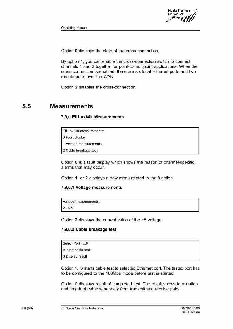
7,9,u EIU nx64k Measurements
EIU nx64k measurements:
0 Fault display
1 Voltage measurements
2 Cable breakage test
Option 0 is a fault display which shows the reason of channel-specificalarms that may occur.
Option 1 or 2 displays a new menu related to the function.
7,9,u,1 Voltage measurements
Voltage measurements:
2 +5 V
Option 2 displays the current value of the +5 voltage.
7,9,u,2 Cable breakage test
Select Port 1...6
to start cable test:
0 Display result
Option 1...6 starts cable test to selected Ethernet port. The tested port hasto be configured to the 100Mbs mode before test is started.
Option 0 displays result of completed test. The result shows terminationand length of cable separately from transmit and receive pairs.
56 (59) # Nokia Siemens Networks DN70285989Issue 1-0 en
Operating manual
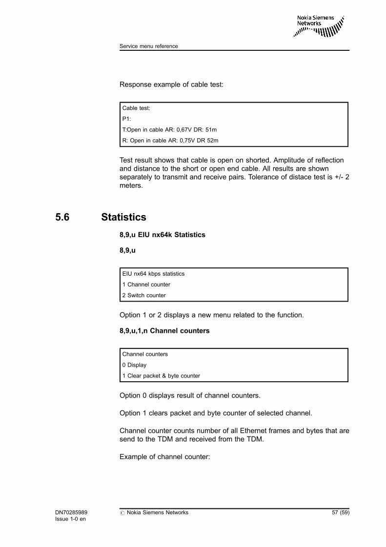
Response example of cable test:
Cable test:
P1:
T:Open in cable AR: 0,67V DR: 51m
R: Open in cable AR: 0,75V DR 52m
Test result shows that cable is open on shorted. Amplitude of reflectionand distance to the short or open end cable. All results are shownseparately to transmit and receive pairs. Tolerance of distace test is +/- 2meters.
5.6 Statistics
8,9,u EIU nx64k Statistics
8,9,u
EIU nx64 kbps statistics
1 Channel counter
2 Switch counter
Option 1 or 2 displays a new menu related to the function.
8,9,u,1,n Channel counters
Channel counters
0 Display
1 Clear packet & byte counter
Option 0 displays result of channel counters.
Option 1 clears packet and byte counter of selected channel.
Channel counter counts number of all Ethernet frames and bytes that aresend to the TDM and received from the TDM.
Example of channel counter:
DN70285989Issue 1-0 en
# Nokia Siemens Networks 57 (59)
Service menu reference
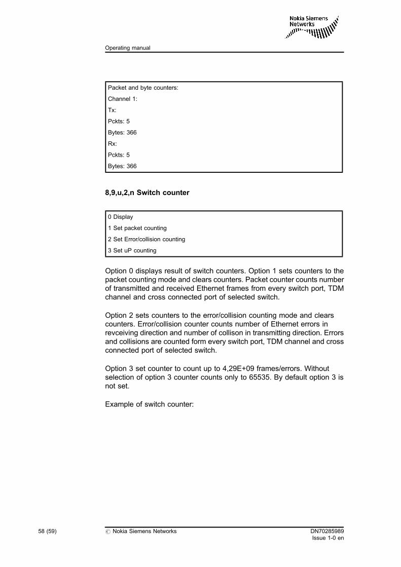
Packet and byte counters:
Channel 1:
Tx:
Pckts: 5
Bytes: 366
Rx:
Pckts: 5
Bytes: 366
8,9,u,2,n Switch counter
0 Display
1 Set packet counting
2 Set Error/collision counting
3 Set uP counting
Option 0 displays result of switch counters. Option 1 sets counters to thepacket counting mode and clears counters. Packet counter counts numberof transmitted and received Ethernet frames from every switch port, TDMchannel and cross connected port of selected switch.
Option 2 sets counters to the error/collision counting mode and clearscounters. Error/collision counter counts number of Ethernet errors inrevceiving direction and number of collison in transmitting direction. Errorsand collisions are counted form every switch port, TDM channel and crossconnected port of selected switch.
Option 3 set counter to count up to 4,29E+09 frames/errors. Withoutselection of option 3 counter counts only to 65535. By default option 3 isnot set.
Example of switch counter:
58 (59) # Nokia Siemens Networks DN70285989Issue 1-0 en
Operating manual
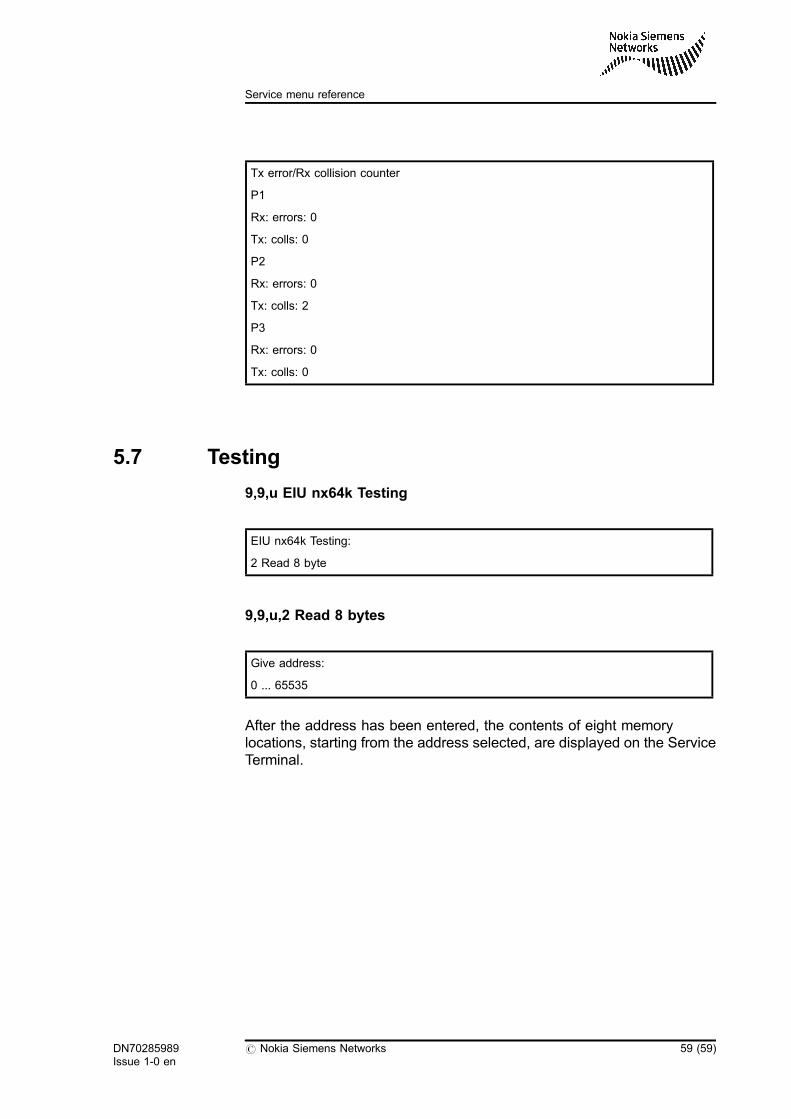
Tx error/Rx collision counter
P1
Rx: errors: 0
Tx: colls: 0
P2
Rx: errors: 0
Tx: colls: 2
P3
Rx: errors: 0
Tx: colls: 0
5.7 Testing
9,9,u EIU nx64k Testing
EIU nx64k Testing:
2 Read 8 byte
9,9,u,2 Read 8 bytes
Give address:
0 ... 65535
After the address has been entered, the contents of eight memorylocations, starting from the address selected, are displayed on the ServiceTerminal.
DN70285989Issue 1-0 en
# Nokia Siemens Networks 59 (59)
Service menu reference