el-o-matic e and p series (product discontinued)...technical details, standard actuator e/p actuator...
TRANSCRIPT
EL-O-Matic E and P Series (Product Discontinued)Technical Data Pneumatic Rack and Pinion Actuators
Copyright © Emerson. The information in this document is subject to change without notice. Updated data sheets can be obtained from our website www.emerson.com/el-o-matic or from your nearest Actuation Technologies Center: America: +1 281 477 4100 Europe: +36 22 530 950 Asia Pacific: +65 6777 8211 Middle East: +971 4 811 8100
EL MaticTMEL MaticTM
Product Data sheetDOC.DSE.PN.UK Rev. 0October 2017

TECHNICAL DETAILS, STANDARD ACTUATOR E/P
ACTUATOR TYPE E12 E25 E40 E65 E100 E150 E200 E350 E600 E950 E1600 P2500 P4000
Bore mm. 46 56 70 80 91 103 110 145 175 200 230 300 325Stroke mm. 12.6 15.7 18.8 22 25.1 31.4 37.7 37.7 44 50.3 62.8 56.5 81.7
Weight:Double acting kg. 0.6 1.3 1.8 2.4 3.1 4.8 5.8 10.4 19.4 26.4 42.7 56.8 86.6Spring return kg. 0.7 1.7 2.4 3.6 4.6 6.9 9.1 16.9 27.6 38.6 65.8 88.2 131.8
Operating time sec. 0.4 0.5 0.7 1.1 1.2 1.8 2.3 3.6 4.5 5.4 6.9 7 12
Air consumptionat 1 atm (litres)
port A stroke 0.1 0.1 0.2 0.3 0.4 0.73 0.8 1.8 2.9 4.7 7.3 8 13.5port B stroke 0.1 0.1 0.2 0.4 0.5 0.65 1 1.9 3.1 4.9 8.0 9.3 17.5
SpecificationPressure range : Double acting 0.2 to 8 bar : Spring return 6 to 8 bar, with max. spring set 3 to 8 bar, reduced spring quantity : 180° actuators 6 bar g maximumTorque : 14.6 to 4955 Nm at 6 bar supply
See torque data sheets 1.104.01 and 1.104.02Operating media : Air, dry or lubricated and inert gasses : For sub-zero applications take appropriate measuresTemperature : -20° to +80°CLubrication : Factory lubricated for the normal life of the actuatorConstruction : Suitable for indoor and outdoor installationFinish : Polyester non-TGIC based powder coating
(see data sheet 4.204.01)Rotation : 91.5° (-0.5° CW to 91° CCW)Double acting : Standard counter clockwise with port "A" pressurized
(code A, see data sheet 1.503 for other assembly codes)
Spring return : Clockwise fail action (code A, see data sheet 1.504 for other assembly codes)
Limit stops : Standard on E-Series. Adjustable range 91°/80° : Optional on P-Series. See data sheet 1.501.01 : For double stroke adjustment. See data sheet 1.501.05
European Directives
91.5°
A B
A B
A B
E-Series
ED = Double acting ES = Spring return
91.5°
A B
A B
A B
11° Adjustable range*
91° Open* only
standard on E-Series actuators
-0.5° Closed
91.5°
A B
A B
A B
P-Series
PD = Double acting PS = Spring return
PED : All actuators are suitable for use with Group 2 gasses according to Pressure Equipment Directive 97/23/EC
: Optional : actuators suitable for use with Group 1 gasses
ATEX : All basic actuators are suitable for use in hazardous area's classified II 2 GD, zones 1 or 2 (Gasses) and 21 or 22 (Dust)
RoHS : This product is only intended for use in large-scale fixed installations excluded from the scope of Directive 2011/65/EU on the restriction of the use of certain hazardous substances in electrical and electronic equipment (RoHS 2).
Russian ApprovalsEl-O-Matic E and P series pneumatic actuators are available with the GOST-R and Rostechnadzor (RTN) approvals.
Note1. Operating time is average with actuator under load
and solenoid valve fitted.2. Air consumption is the actual free air volume at 1 atm.3. Pressure is in barg.
Product Data sheet
Copyright © Emerson. The information in this document is subject to change without notice. Updated data sheets can be obtained from our website www.emerson.com/el-o-matic or from your nearest Actuation Technologies Center: America: +1 281 477 4100 Europe: +36 22 530 950 Asia Pacific: +65 6777 8211 Middle East: +971 4 811 8100
EL MaticTMEL MaticTM
1.102 Rev. 0October 2017
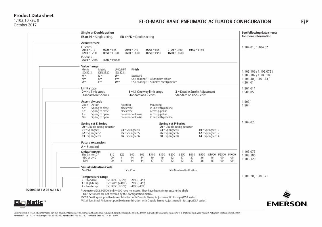
EL-O-MATIC BASIC PNEUMATIC ACTUATOR CONFIGURATION E/P
Single or Double action ES or PS = Single acting, ED or PD = Double acting
Actuator sizeE-Series0012 = E12 0025 = E25 0040 = E40 0065 = E65 0100 = E100 0150 = E1500200 = E200 0350 = E 350 0600 = E600 0950 = E950 1600 = E1600
P-Series2500 = P2500 4000 = P4000
Valve flange Metric Metric UNC/NPT FinishISO 5211 DIN 3337 ISO 5211 M = D = U = StandardN = E = V = CSR coating (2 + Aluminium pinionO = F = W = CSR coating (2 + Stainless Steel pinion (3
Limit stops0 = No limit stops 1 = L1 One way limit stops 2 = Double Stroke AdjustmentStandard on P-Series Standard on E-Series Standard on DSA-Series
Assembly codeCode Action Rotation MountingA = Spring to close clock wise in line with pipelineB = Spring to close clock wise across pipelineC = Spring to open counter clock wise across pipelineD = Spring to open counter clock wise in line with pipeline
Spring set E-Series Spring set P-Series00 = Double acting actuator 00 = Double acting actuator01 = Springset 1 04 = Springset 4 04 = Springset 4 10 = Springset 1002 = Springset 2 05 = Springset 5 06 = Springset 6 12 = Springset 1203 = Springset 3 06 = Springset 6 08 = Springset 8 14 = Springset 14
Future expansionA = Standard
Default InsertSize (in mm.) (1 E12 E25 E40 E65 E100 E150 E200 E 350 E600 E950 E1600 P2500 P4000- ISO or UNC 00 11 14 14 19 19 22 27 27 36 46 00 00- DIN 00 11 14 14 17 17 22 22 27 36 46 00 00
Visual Indication CodeD = Disk K = Knob N = No visual indication
Temperature range0 = Standard TS: 80°C (176°F) -20°C ( -4°F)1 = High temp TS: 120°C (248°F) -20°C ( -4°F)2 = Low temp TS: 80°C (176°F) -40°C (-40°F)
ES 0040.M 1 A 05 A.14 N 1 (1 Actuators E12, P2500 and P4000 have no inserts. They have have a inner square the shaft 180° actuators are not covered by this configuration matrix.(2 CSR Coating not possible in combination with Double Stroke Adjustment limit stops (DSA series).(3 Stainless Steel Pinion not possible in combination with Double Stroke Adjustment limit stops (DSA series).
See following data sheets for more information
1.104.01 / 1.104.02
1.103.106 / 1.103.073 /1.103.102 / 1.103.1031.101.30 / 1.101.33 /4.204.01
1.501.01/1.501.05
1.503/1.504
1.104.02
1.103.0731.103.1061.103.120
1.101.70 / 1.101.71
Product Data sheet
Copyright © Emerson. The information in this document is subject to change without notice. Updated data sheets can be obtained from our website www.emerson.com/el-o-matic or from your nearest Actuation Technologies Center: America: +1 281 477 4100 Europe: +36 22 530 950 Asia Pacific: +65 6777 8211 Middle East: +971 4 811 8100
EL MaticTMEL MaticTM
1.102.10 Rev. 0October 2017
1.501.01 Rev. 0October 2017
EL-O-MATIC ACTUATOR WITH ONE WAY LIMIT STOPS L1/LF
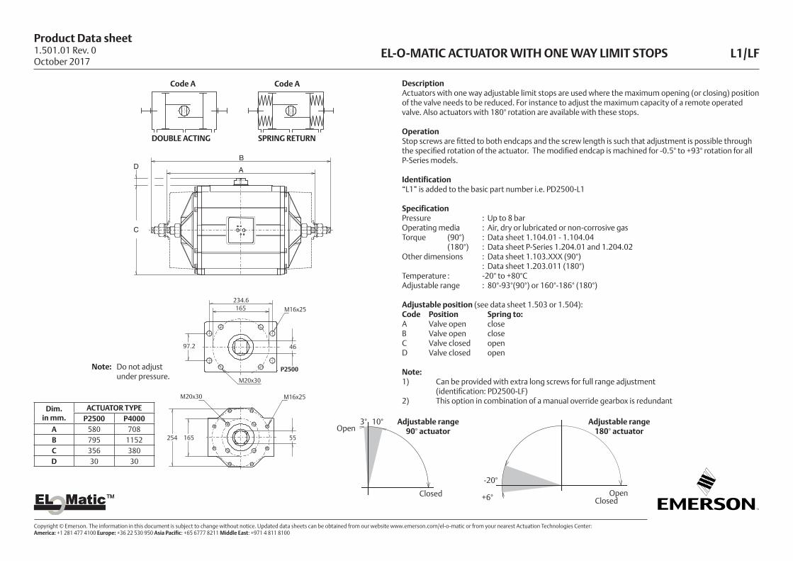
DescriptionActuators with one way adjustable limit stops are used where the maximum opening (or closing) position of the valve needs to be reduced. For instance to adjust the maximum capacity of a remote operated valve. Also actuators with 180° rotation are available with these stops.
OperationStop screws are fitted to both endcaps and the screw length is such that adjustment is possible through the specified rotation of the actuator. The modified endcap is machined for -0.5° to +93° rotation for all P-Series models.
Identification“L1” is added to the basic part number i.e. PD2500-L1
SpecificationPressure : Up to 8 barOperating media : Air, dry or lubricated or non-corrosive gasTorque (90°) : Data sheet 1.104.01 - 1.104.04 (180°) : Data sheet P-Series 1.204.01 and 1.204.02Other dimensions : Data sheet 1.103.XXX (90°) : Data sheet 1.203.011 (180°)Temperature : -20° to +80°CAdjustable range : 80°-93°(90°) or 160°-186° (180°)
Adjustable position (see data sheet 1.503 or 1.504):Code Position Spring to:A Valve open closeB Valve open closeC Valve closed openD Valve closed open
Note:1) Can be provided with extra long screws for full range adjustment (identification: PD2500-LF)2) This option in combination of a manual override gearbox is redundant
Dim.in mm.
ACTUATOR TYPEP2500 P4000
A 580 708B 795 1152C 356 380D 30 30
B
A
C
D
Note: Do not adjust under pressure.
DOUBLE ACTING SPRING RETURN
Code ACode A
234.6165
97.2
M16x25
P2500
M20x30
46
M16x25
55254 165
M20x30
B
A
C
D
3° 10°Open
Adjustable range 90° actuator
Adjustable range 180° actuator
-20°
+6° OpenClosed
Closed
Product Data sheet
Copyright © Emerson. The information in this document is subject to change without notice. Updated data sheets can be obtained from our website www.emerson.com/el-o-matic or from your nearest Actuation Technologies Center: America: +1 281 477 4100 Europe: +36 22 530 950 Asia Pacific: +65 6777 8211 Middle East: +971 4 811 8100
EL MaticTMEL MaticTM
LIMIT STOP PLATE DIMENSIONS LS 420
E
Gmax.
F
W O
V
O
Hmax.
-15°
+0.5°
+1°
Open
Closed
Adjustable range 90° actuators
Dim.in mm.
ACTUATOR TYPEP2500 P4000
E 466 490F 135 135G 322 322H 130 141O 46 55V 165 165W M20x30 M20x30
DescriptionThese limit stop plates are used when precise control is required for both end of stroke positions.It is possible to adjust 15° of both ends of the standard stroke.
ConstructionThe complete stop plate assembly may be added to the 90° P- series actuators.The assembly is normally sandwiched between the actuator and mounting surface of the valve or bracket. Bearing rings are used at both surfaces to provide a long life expectancy.
The unit is assembled with a drive adaptor which passes through the stop plate, into the square actuator and provides the coupling between the two components.This drive adaptor normally also accommodates the coupling of the valve stem.
Identification"LS420" is added to the basic part number i.e. PD2500-LS420
Other dimensionsSee data sheet 1.103.xxx
OptionVersion for 180° or DIN-standard actuator
E
Gmax.
F
W O
V
O
Hmax.
Drive shaft
Actuator base
Drive adaptor
Cover plate
CamHousing limit stop
Flange according ISO 5211
Flange according DIN 3337
Note:Cover plate only in combination with P2500
1.501.03 Rev. 0October 2017

Product Data sheet
Copyright © Emerson. The information in this document is subject to change without notice. Updated data sheets can be obtained from our website www.emerson.com/el-o-matic or from your nearest Actuation Technologies Center: America: +1 281 477 4100 Europe: +36 22 530 950 Asia Pacific: +65 6777 8211 Middle East: +971 4 811 8100
EL MaticTMEL MaticTM
EL-O-MATIC ACTUATOR WITH DOUBLE STROKE ADJUSTMENT DSA
Dim. Actuator typein mm E25 E40 E65 E100 E150 E200 E350 E600 E950 E1600A DA 159 180 199 221 254 283 305 390 440 520B SR 172 204 249 267 310 360 387 480 532 641
C 80 93 105 118 140 143 181 220 259 297D 20 20 20 20 20 20 20 30 30 30H 74 86 98 108 121 128 173 207 231 264I 46 51 57.5 63 70 73 94.3 113 126 142
J1 28.3 35.1 40 43.7 48.7 53.9 72.5 88.8 102.4 114.4L 11.5 15.5 15.5 18.5 24.6 24.6 24.6 41.5 41.5 47.5Y M6 M8 M8 M10 M10 M12 M12 M16 M16 M20X 36 41.5 41.5 50.5 60 62.5 72.5 102 102 109.5
X max. 41.5 48.5 48.5 58.5 67 74 84 114.5 114.5 124
Y
AB
C
H
IX
J1
LL
1 2
D
3° 10°
3°
15°
adjustable range
Closedstopscrew (1)
Openstopscrew (2)
Factory option: Fail to Open Y
AB
C
H
IX
J1
LL
1 2
D
3° 10°
3°
15°
Stroke adjustment cam
Factory option: "Fail open"
DescriptionActuators with double stroke adjustment are normally used for high performance butterfly valves where a fine adjustment is required for the closed position. In this version adjustment is provided at the end of the opening and closing stroke positions. DSA actuators may be double acting or spring return, though are normally used as spring return (fail close) actuators.
OperationThe closed position is adjusted by means of the stop-screw (1) located in the actuator body and for the open position by the stop-screws (2) in the actuator end caps.
IdentificationSee data sheet A 1.102.10.
SpecificationPressure : Up to 8 barOperating media : Air, dry or lubricated or non-corrosive gasTorque (90°) : Data sheet 1.104.01 - 1.104.02Rotation - Spring return : Clock-wise on air failure. Double acting : Counter clock-wise with port “A” pressurised.Other dimensions : Data sheet 1.103.XXXTemperature : -20° to +80°CAdjustable range : Closed position (1), +3°/- 15° Open position (2), 80° - 93°Note1) Can be provided with extra long end-cap stop screws for full range adjustment of the “open” position.2) This DSA option is not required on actuators fitted with manual override gearboxes, as MO gearboxes
already incorporate this function.
Important1) "Fail open" is factory option.2) When assembled for “fail open” operation (code D; see data sheet 1.504), both stop-screws (1)
and (2) will adjust the closed position. There is no adjustment for the open position!
1.501.05 Rev. 0October 2017
Product Data sheet
Copyright © Emerson. The information in this document is subject to change without notice. Updated data sheets can be obtained from our website www.emerson.com/el-o-matic or from your nearest Actuation Technologies Center: America: +1 281 477 4100 Europe: +36 22 530 950 Asia Pacific: +65 6777 8211 Middle East: +971 4 811 8100
EL MaticTMEL MaticTM
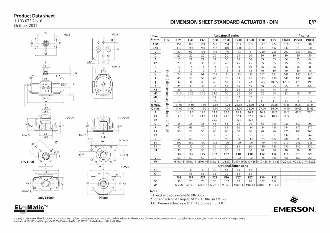
DIMENSION SHEET STANDARD ACTUATOR - DIN E/P
R
øP+0.50
S
S
R2
øKøK1
M1M2 N ±0.5
øVO
W
J
2øQAB
øP2øP1
EF G
D
C
E2
H
M1
øK
N ±0.5
øP+0.50
øVO
WS
R
øV
W
R R2
T1
U1 R1
S1
A
B
I
P-series
32
24G1/4"
M5x8
M6x12
E-series
E25-E950
P2500
P4000Only E1600
M5x8
Max. 5 Max. 5
M16x25234.6
97.2
M16x25
234.6
97.2
Dim.in mm.
Actuators E-series P-seriesE 12 E 25 E 40 E 65 E100 E150 E200 E 350 E600 E950 E1600 P2500 P4000
A DA 159 180 199 221 254 283 305 387 424 516 378 502B SR 172 204 249 267 310 360 387 477 517 637 570 834
C 80 93 105 118 140 143 181 220 259 297 356 380D 20 20 20 20 20 20 20 30 30 30 30 30E 16 22 22 22 36 36 36 55 55 64 55 64
E2 23 30 30 30 45 45 45 65 65 75 65 80F 10 14 14 14 19 19 19 36 36 36 36 36G 12 12 12 12 12 12 12 10 10 10 10 10H 74 86 98 108 121 128 173 207 231 265 350 380I 46 53 58 63 70 73 95 113 126 142 183 200J 32 34 40 45 59 51 73 84.5 105.5 120.5 178 190K 24 33 33 38 55 55 55 68 75 95 85 120
K1 29 32 32 40 50 54 54 68 75 95 - -M1 34.5 34.5 34.5 34.5 50 50 50 52 64 82 66 77M2 - - - 27 - 37 37 - - - - -N 3 3 3 3.5 3.5 3.5 3.5 3.5 3.5 3.5 3 1.5
O max. 11.08 14.08 14.08 17.08 17.08 22.10 22.10 27.11 36.16 46.16 46.21 55.24O min. 11.00 14.00 14.00 17.00 17.00 22.00 22.00 27.00 36.00 46.00 46.05 55.05
P 14.1 18.1 18.1 22.2 22.5 28.2 36.2 36.2 48.2 60.2 60.2 72.2P1 14.1 18.1 21.1 23.1 28.5 32.1 32.1 36.5 48.5 60.5 - -P2 - - - 25.2 - 36.2 36.2 - - - - -Q 35 35 35 55 55 70 70 85 100 130 130 200R 52 65 70 70 86 90 114 124 130 154 170 170
R1 50 50 50 60 60 60 60 90 90 125 160 160R2 - - - - - - - - - 132 - 262S 52 65 70 70 92 90 114 124 142 280 290 290
S1 100 100 100 100 100 100 100 170 170 210 245 245T1 80 80 80 80 80 80 80 130 130 130 130 130U1 30 30 30 30 30 30 30 30 30 30 30 30
F05 F05 F05 F07 F07 F10 F10 F12 F14 F16 F16 F25V 50 50 50 70 70 102 102 125 140 165 165 254W M10 x 16 M10 x 16 M10 x 16 M8 x 13 M8 x13 M10 x 16 M10 x 16 M12 x 20 M16 x 25 M20 x 30 M20 x 30 M16 x 25
Optional dimensionsK1' - 40 40 32 54 50 50 - - - - -Q' - 55 55 35 70 55 55 - - - - -
F03 F07 F07 F05 F10 F07 F07 F10 F10 - - -V' 36 70 70 50 102 70 70 102 102 - - -W' M5 x 8 M8 x 13 M8 x 13 M6 x 10 M10x16 M8 x 13 M8 x 13 M10x 16 M10 x 16 - - -
For E12 dim
ensions see data sheet 1.103.103
Note1. Flange and square drive to DIN 33372. Top and solenoid flange to VDI\VDE 3845 (NAMUR)3. For P-series actuators with limit stops see 1.501.01
1.103.073 Rev. 0October 2017

Product Data sheet
Copyright © Emerson. The information in this document is subject to change without notice. Updated data sheets can be obtained from our website www.emerson.com/el-o-matic or from your nearest Actuation Technologies Center: America: +1 281 477 4100 Europe: +36 22 530 950 Asia Pacific: +65 6777 8211 Middle East: +971 4 811 8100
EL MaticTMEL MaticTM
DIMENSION SHEET STANDARD ACTUATOR - ISO E/P
Dim.in mm.
Actuators E-series P-seriesE 12 E 25 E 40 E 65 E100 E150 E200 E 350 E600 E950 E1600 P2500 P4000
A DA 159 180 199 221 254 283 305 387 424 516 378 502B SR 172 204 249 267 310 360 387 477 517 637 570 834
C 80 93 105 118 140 143 181 220 259 297 356 380D 20 20 20 20 20 20 20 30 30 30 30 30E 16 22 22 22 36 36 36 55 55 64 55 64
E2 23 30 30 30 45 45 45 65 65 75 65 80F 10 14 14 14 19 19 19 36 36 36 36 36G 12 12 12 12 12 12 12 10 10 10 10 10H 74 86 98 108 121 128 173 207 231 265 350 380I 46 53 58 63 70 73 95 113 126 142 183 200J 32 34 40 45 59 51 73 84.5 105.5 120.5 178 190K 24 33 33 38 55 55 55 68 75 95 85 120
M1 34.5 34.5 34.5 34.5 50 50 50 52 64 82 66 77M2 - - - 27 - 37 37 - - - - -N 1 1 1 1.5 1 1.5 1.5 1.5 1.5 1.5 3 1.5
O max. 11.08 14.08 14.08 19.08 19.08 22.10 27.11 27.11 36.16 46.16 46.21 55.24O min. 11.00 14.00 14.00 19.00 19.00 22.00 27.00 27.00 36.00 46.00 46.00 55.00
P 14.1 18.1 18.1 25.2 25.5 28.2 36.2 36.2 48.2 60.2 60.2 72.2P1 14.1 18.1 21.1 23.1 28.5 32.1 32.1 36.5 48.5 60.5 - -P2 - - - 25.2 - 36.2 36.2 - - - - -R 52 65 70 70 86 90 114 124 130 154 170 170
R1 50 50 50 60 60 60 60 90 90 125 160 160R2 - - - - - - - - - 132 - 262S 52 65 70 70 92 90 114 124 142 280 290 290
S1 100 100 100 100 100 100 100 170 170 210 245 245T - - - - - - - - - 234.6 234.6 -
T1 80 80 80 80 80 80 80 130 130 130 130 130U - - - - - - - - - 97.2 97.2 -
U1 30 30 30 30 30 30 30 30 30 30 30 30F03 F05 F05 F05 F07 F07 F07 F10 F10 F16 F16 F16
V 36 50 50 50 70 70 70 102 102 165 165 165W M5 x 8 M6 x 10 M6 x 10 M6 x 10 M8 x 13 M8 x 13 M8 x 13 M10 x 16 M10 x 16 M20 x 30 M20 x 30 M20 x 30
F05 F07 F07 F07 F10 F10 F10 F12 F14 - - F25V1 50 70 70 70 102 102 102 125 140 - - 254W1 M6 x 10 M8 x 13 M8 x 13 M8 x 13 M10 x 16 M10 x 16 M10 x 16 M12 x 20 M16 x 25 - - M16 x 25
Note1. Flange and square drive to ISO 52112. Top and solenoid flange to VDI/VDE 3845 (NAMUR)3. For P-series actuators with limit stops see 1.501.01
For E12 dim
ensions see data sheet 1.103.102
R
øP
S
S
R2
øK
W1
M1M2 N ±0.5
øV
O
W
J
AB
øP2øP1
EF G
D
C
E2
H
M1
øK
N ±0.5
øP+0
.50 øV
O
WS
R
øV
W1
R R2
T1
U1 R1
S1
A
B
I
øV1
øV1
W
P4000
P2500
P-series
4
M5x8
32
4
G¼" 24
M6x12
M5x8
E-series
Only E1600
E25-E950
M16x25
234.6
97.2
M16x25
234.6
97.2
4
1.103.106 Rev. 0October 2017

Product Data sheet
Copyright © Emerson. The information in this document is subject to change without notice. Updated data sheets can be obtained from our website www.emerson.com/el-o-matic or from your nearest Actuation Technologies Center: America: +1 281 477 4100 Europe: +36 22 530 950 Asia Pacific: +65 6777 8211 Middle East: +971 4 811 8100
EL MaticTMEL MaticTM
DIMENSION SHEET ACTUATOR ISO E12 (90°/180°)
W1
X
L
L1
A
B
øP+0
.50 øV
R
W
M N ±0.5
O
T W2
U U1
E
F
G
D
K1
K
C
J
E2
YI
H
Note: Dotted image represents optional NAMUR solenoid interface block
DOUBLE ACTING TORQUE (ED)
Pressure bar 3.5 4 4.5 5 5.5 6 7
Torque 90°/180° Nm 8.5 9.7 10.9 12.2 13.4 14.6 17.1
SINGLE ACTING TORQUE (ES)
Air stroke Spring strokePressure bar 5 6
Position - start end start end start end
Torque 90° Nm 7.6 4.9 10 7.5 7.2 4.6
Torque 180° Nm 7.8 5 10.4 7.6 7.1 4.5
45
15
Dim. in mm 90° 180°
A ED 103 155
B ES 118 216
C 60 60
D 20 20
E 16 16
E2 23 23
F 10 10
G 12 12
H 60 60
I 33 33
J 21 21
K 12.7 12.7
K1 6.4 6.4
L 25.4 25.4
L1 50.8 50.8
M 16.5 16.5
N 1 1
O max. 9.1 9.1
O min. 9 9
P 12.1 12.1
R 40 40
R1 40 40
T 40 40
U 31 31
V 42 42
W M6x8 M6x8
W1 M4x7 M4x7
W2 M4x7 M4x7
X G1/8" G1/8"
Y M6x12 M6x12
M5x8
G1/4"
4
1.103.102 Rev. 0October 2017
Product Data sheet
Copyright © Emerson. The information in this document is subject to change without notice. Updated data sheets can be obtained from our website www.emerson.com/el-o-matic or from your nearest Actuation Technologies Center: America: +1 281 477 4100 Europe: +36 22 530 950 Asia Pacific: +65 6777 8211 Middle East: +971 4 811 8100
EL MaticTMEL MaticTM
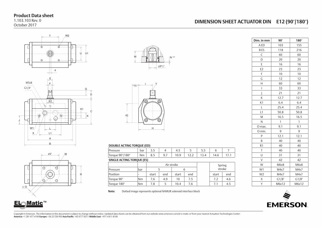
DIMENSION SHEET ACTUATOR DIN E12 (90°/180°)
T W2
U U1
E
F
G
D
K1
K
C
J
E2
YI
HW1
X
L
L1
A
B
P+0.50
øV
R
W
M N ±0.5
O
M5x8
G1/4"
45
15
4
DOUBLE ACTING TORQUE (ED)
Pressure bar 3.5 4 4.5 5 5.5 6 7
Torque 90°/180° Nm 8.5 9.7 10.9 12.2 13.4 14.6 17.1
SINGLE ACTING TORQUE (ES)
Air stroke Spring strokePressure bar 5 6
Position - start end start end start end
Torque 90° Nm 7.6 4.9 10 7.5 7.2 4.6
Torque 180° Nm 7.8 5 10.4 7.6 7.1 4.5
Dim. in mm 90° 180°
A ED 103 155
B ES 118 216
C 60 60
D 20 20
E 16 16
E2 23 23
F 10 10
G 12 12
H 60 60
I 33 33
J 21 21
K 12.7 12.7
K1 6.4 6.4
L 25.4 25.4
L1 50.8 50.8
M 16.5 16.5
N 1 1
O max. 9.1 9.1
O min. 9 9
P 12.1 12.1
R 40 40
R1 40 40
T 40 40
U 31 31
V 42 42
W M6x8 M6x8
W1 M4x7 M4x7
W2 M4x7 M4x7
X G1/8" G1/8"
Y M6x12 M6x12
Note: Dotted image represents optional NAMUR solenoid interface block
1.103.103 Rev. 0October 2017

Product Data sheet
Copyright © Emerson. The information in this document is subject to change without notice. Updated data sheets can be obtained from our website www.emerson.com/el-o-matic or from your nearest Actuation Technologies Center: America: +1 281 477 4100 Europe: +36 22 530 950 Asia Pacific: +65 6777 8211 Middle East: +971 4 811 8100
EL MaticTMEL MaticTM
DRIVE INSERTS FOR EL-O-MATIC ACTUATORS E
DescriptionMost of the El-O-Matic actuators are fitted with drive inserts. This enables actuators to be directly mounted onto suitable valves and eliminates the need for a bracket and coupling type mounting kit. The use of direct mounts significantly cuts the cost of the valve/actuator assembly.
Standard actuators are fitted with square drive inserts in accordance with ISO 5211 (or DIN 3337), but a wide variety of other inserts are also available. Special inserts may have oversize or undersize squares, double-D and shaft key way forms.
Drive inserts can be supplied on factory built actuators or as loose items and are easily replaceable at distributor or end user level.
Where direct mounts are not possible, for instance on valves with exposed grand packing, the use of inserts often simplifies the design of the mounting kit.
Material : Aluminium alloyFinish : Anodised
The following actuator types do not have inserts. - E12,- P2500 and P4000 - 180° actuatorsThese actuators have inner square directly in the bottom of the pinion. See the following data sheets for more information :
E12 ISO5211 1.103.102 DIN 3337 1.103.103
P2500/P4000 DIN 3337 1.103.073 ISO 5211 1.103.106
180° DIN 3337 1.203.011 ISO 5211 1.203.021
Ø P2Ø P1
Ø P2Ø P1
M1 M2M1 M2
Insert mounting acc. DIN 3337
Centering plate
Standard available insert shapes
Insert mounting acc. ISO 5211
sq Max.
D Max.
D Max.
Optional available insert shapes
Dim. in mm
Inserts with inner-square-dimensions per actuator typeE25 E40 / E65 E100 E150 E200 E350 E600 E950 E1600
Standard inserts dimensionsISO5211 11 14 19 19 22 27 27 36 46DIN3337 11 14 17 17 22 22 27 36 46
Optional insert dimensions9 10 12 14 14 14 14 22 -
10 12 14 16 16 16 16 - -- - 16 22 17 17 17 - -- - - 24 19 19 19 - -- - - 27 24 24 24 - -
Maximum insert dimensionsM1 34.5 34.5 34.5 50 50 50 52 64 82M2 - - 27 - 37 37 - - -P1 14.1 18.1 23.1 28.5 32.1 32.1 36.5 48.5 60.5P2 - - 25.2 - 36.2 36.2 - - -
Sq max. 11 16 19 27 27 27 27 36 46D max. 13.8 21 23.6 33.6 33.6 33.6 33.6 45 60
1.103.200 Rev. 0October 2017

Product Data sheet
Copyright © Emerson. The information in this document is subject to change without notice. Updated data sheets can be obtained from our website www.emerson.com/el-o-matic or from your nearest Actuation Technologies Center: America: +1 281 477 4100 Europe: +36 22 530 950 Asia Pacific: +65 6777 8211 Middle East: +971 4 811 8100
EL MaticTMEL MaticTM
DOUBLE ACTING ACTUATOR TORQUE (Nm.) 90°
ActuatorTorque in Nm
Supply Pressure (bar)
Type Size 2 3 3.5 4 4.5 5 5.5 6 6.5 7 8
ED 12 4.8 7.3 8.5 9.7 11.0 12.2 13.4 14.6 15.9 17.1 19.6
ED 25 9 13 16 18 20 23 25 27 29 32 36
ED 40 17 25 29 34 38 42 47 51 55 59 68
ED 65 25 38 45 51 58 64 71 77 84 90 104
ED 100 38 57 66 76 86 95 105 115 124 134 153
ED 150 60 91 106 122 137 153 168 183 199 214 245
ED 200 82 124 146 167 188 209 230 251 272 293 335
ED 350 143 216 253 290 326 363 400 436 473 510 583
ED 600 243 368 430 492 554 617 679 741 804 866 991
ED 950 363 549 642 735 828 921 1014 1107 1200 1293 1479
ED 1600 600 907 1061 1214 1368 1522 1676 1829 1983 2137 2444
PD 2500 958 1449 1694 1940 2186 2431 2677 2922 3168 3413 3904
PD 4000 1623 2456 2872 3289 3705 4121 4537 4954 5370 5786 6619
Note1. Emerson recommends that the valve manufacturer supply the maximum required torque values
(Including any adjustments or suggested safety factors for valve service conditions or application). Additionally, the valve manufacturer must identify at which position(s) and direction(s) of rotation
(Counter Clock Wise or Clock Wise) these maximum requirements occur. 2. If in doubt, or you require any assistance with sizing actuators, do not hesitate to contact your
nearest Emerson's Valve Automation Division representative.3 Pressure on port "A" opens the actuator*4 The actuator is shown in closed position*
(* code A, data sheet 1.503)
91.5°
-0.5°
91°
A B
CLOSED
OPEN
Rotation
Start End
Torque
DOUBLE ACTING TORQUE
1.104.01 Rev. 0October 2017
Product Data sheet
Copyright © Emerson. The information in this document is subject to change without notice. Updated data sheets can be obtained from our website www.emerson.com/el-o-matic or from your nearest Actuation Technologies Center: America: +1 281 477 4100 Europe: +36 22 530 950 Asia Pacific: +65 6777 8211 Middle East: +971 4 811 8100
EL MaticTMEL MaticTM
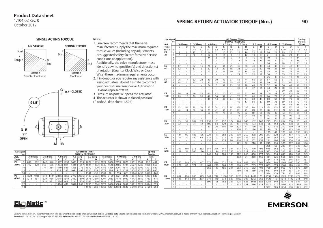
SPRING RETURN ACTUATOR TORQUE (Nm.) 90°
Springsetnr.
Air Stroke (Nm) Spring StrokeSUPPLY PRESSURE
Act.Type
3.0 barg 3.5 barg 4.0 barg 4.5 barg 5.0 barg 5.5 barg 6.0 barg 7.0 barg (Nm)C D C D C D C D C D C D C D C D E F
ES 12 2 - - 3.8 1.0 5.1 2.3 6.4 3.6 7.7 4.9 9.0 6.2 10.3 7.5 12.9 10.1 7.2 4.6ES 25
2 3 4 5 6
9 6 12 9 14 11 16 13 19 16 21 18 24 21 29 25 7 47 2 9 5 12 7 14 9 16 12 19 14 21 17 26 21 11 7- - - - 9 3 11 5 14 8 16 10 19 13 23 17 14 9- - - - - - - - 11 4 14 6 16 8 21 13 18 11- - - - - - - - - - - - 14 4 18 9 21 13
ES 40
2 17 12 22 16 26 21 31 25 35 30 40 34 44 39 53 48 13 83 12 4 17 8 22 13 26 18 31 22 35 27 40 31 49 40 20 124 - - - - 17 5 21 10 26 14 30 19 35 23 44 33 26 175 - - - - - - - - 21 7 26 11 30 16 39 25 33 216 - - - - - - - - - - - - 25 8 34 17 40 25
ES 65
2 26 17 32 23 39 30 46 37 53 44 60 51 67 58 81 72 21 133 18 5 25 11 32 18 39 25 46 32 52 39 59 46 73 60 32 204 - - - - 24 6 31 13 38 20 45 27 52 34 66 48 42 265 - - - - - - - - 30 8 37 15 44 22 58 36 53 336 - - - - - - - - - - - - 37 10 50 23 63 40
ES 100
2 39 27 49 37 60 47 70 57 80 67 90 78 100 88 121 108 29 183 29 10 39 20 49 30 59 41 70 51 80 61 90 71 110 92 44 274 - - - - 39 14 49 24 59 34 69 44 80 54 100 75 58 375 - - - - - - - - 49 17 59 27 69 38 89 58 73 466 - - - - - - - - - - - - 59 21 79 41 88 55
ES 150
2 63 41 79 58 95 74 112 90 128 107 144 123 161 139 193 172 48 293 46 14 62 30 79 47 95 63 111 79 128 96 144 112 177 145 72 444 - - - - 62 19 78 36 95 52 111 68 127 85 160 117 95 585 - - - - - - - - 78 24 94 41 110 57 143 90 119 736 - - - - - - - - - - - - 94 30 126 62 143 88
ES 200
2 85 57 107 79 130 101 152 124 174 146 197 169 219 191 264 236 65 413 62 19 84 42 106 64 129 86 151 109 173 131 196 153 240 198 98 614 - - - - 83 26 105 49 127 71 150 93 172 116 217 160 131 825 - - - - - - - - 104 33 126 56 149 78 193 123 164 1026 - - - - - - - - - - - - 125 41 170 85 196 123
ES 350
2 144 96 183 135 221 174 260 213 299 252 338 290 377 329 454 407 116 743 101 30 140 68 179 107 217 146 256 185 295 224 334 263 412 340 174 1124 - - - - 136 41 175 80 214 118 252 157 291 196 369 274 232 1495 - - - - - - - - 171 52 210 91 249 130 326 207 289 1866 - - - - - - - - - - - - 206 63 283 141 347 223
ES 600
2 249 166 315 232 381 298 447 364 513 430 579 496 645 562 777 694 195 1223 179 54 245 120 311 186 377 252 443 318 509 384 575 450 707 582 292 1834 - - - - 240 74 306 140 372 206 438 272 504 338 636 470 389 2455 - - - - - - - - 302 94 368 160 434 226 566 358 487 3066 - - - - - - - - - - - - 364 114 496 246 584 367
ES 950
2 375 249 474 347 572 446 671 544 769 643 868 741 966 840 1163 1037 290 1793 272 82 371 181 469 279 568 378 666 476 765 575 863 673 1060 870 434 2694 - - - - 366 113 465 211 563 310 662 408 760 507 957 704 579 3595 - - - - - - - - 460 143 559 242 657 340 854 537 724 4486 - - - - - - - - - - - - 554 174 751 371 869 538
ES 1600
2 617 416 780 579 943 742 1106 905 1269 1068 1432 1231 1594 1394 1920 1719 474 2993 445 144 608 307 771 470 934 633 1097 796 1260 959 1423 1121 1748 1447 711 4494 - - - - 599 198 762 361 925 523 1088 686 1251 849 1577 1175 947 5985 - - - - - - - - 753 251 916 414 1079 577 1405 903 1184 7486 - - - - - - - - - - - - 907 305 1233 630 1421 897
Springsetnr.
Air Stroke (Nm) Spring StrokeSUPPLY PRESSURE
Act.Type
3.0 barg 3.5 barg 4.0 barg 4.5 barg 5.0 barg 5.5 barg 6.0 barg 7.0 barg (Nm)C D C D C D C D C D C D C D C D E F
PS 2500
6 896 602 1142 848 1387 1093 1633 1339 1879 1585 2124 1830 2370 2076 2861 2567 792 4978 712 320 958 566 1203 811 1449 1057 1694 1302 1940 1548 2186 1794 2677 2285 1056 663
10 - - 774 284 1019 529 1265 775 1510 1020 1756 1266 2001 1511 2492 2002 1321 82912 - - - - 835 247 1081 492 1326 738 1572 984 1817 1229 2308 1720 1585 99514 - - - - - - - - 1142 456 1387 701 1633 947 2124 1438 1849 1160
PS 4000
6 1524 1028 1940 1444 2356 1860 2772 2276 3189 2693 3605 3109 4021 3525 4854 4358 1337 8398 1213 551 1629 968 2045 1384 2462 1800 2878 2216 3294 2633 3710 3049 4543 3882 1783 1119
10 - - 1318 491 1734 908 2151 1324 2567 1740 2983 2157 3400 2573 4232 3405 2229 139912 - - - - 1424 431 1840 848 2256 1264 2672 1680 3089 2097 3921 2929 2674 167914 - - - - - - - - 1945 788 2362 1204 2778 1620 3610 2453 3120 1958
SINGLE ACTING TORQUE
91.5°
CF
D E
-0.5°
91°
A B
OPEN
CLOSED
FEnd
RotationClockwise
DEnd
RotationCounter Clockwise
CStart
SPRING STROKEAIR STROKE
Torque
EStart
Note1. Emerson recommends that the valve
manufacturer supply the maximum required torque values (Including any adjustments or suggested safety factors for valve service conditions or application).
Additionally, the valve manufacturer must identify at which position(s) and direction(s) of rotation (Counter Clock Wise or Clock Wise) these maximum requirements occur.
2. If in doubt, or you require any assistance with sizing actuators, do not hesitate to contact your nearest Emerson's Valve Automation Division representative.
3 Pressure on port "A" opens the actuator*4 The actuator is shown in closed position* (* code A, data sheet 1.504)
1.104.02 Rev. 0October 2017
Product Data sheet
Copyright © Emerson. The information in this document is subject to change without notice. Updated data sheets can be obtained from our website www.emerson.com/el-o-matic or from your nearest Actuation Technologies Center: America: +1 281 477 4100 Europe: +36 22 530 950 Asia Pacific: +65 6777 8211 Middle East: +971 4 811 8100
EL MaticTMEL MaticTM
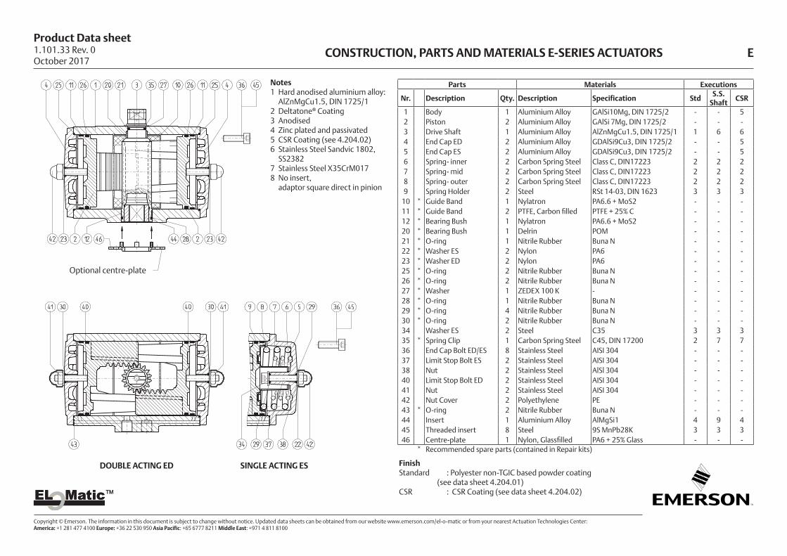
Parts Materials Executions
Nr. Description Qty. Description Specification StdS.S.
ShaftCSR
1 Body 1 Aluminium Alloy GAlSi10Mg, DIN 1725/2 - - 52 Piston 2 Aluminium Alloy GAlSi 7Mg, DIN 1725/2 - - -3 Drive Shaft 1 Aluminium Alloy AlZnMgCu1.5, DIN 1725/1 1 6 64 End Cap ED 2 Aluminium Alloy GDAlSi9Cu3, DIN 1725/2 - - 55 End Cap ES 2 Aluminium Alloy GDAlSi9Cu3, DIN 1725/2 - - 56 Spring- inner 2 Carbon Spring Steel Class C, DIN17223 2 2 27 Spring- mid 2 Carbon Spring Steel Class C, DIN17223 2 2 28 Spring- outer 2 Carbon Spring Steel Class C, DIN17223 2 2 29 Spring Holder 2 Steel RSt 14-03, DIN 1623 3 3 3
10 * Guide Band 1 Nylatron PA6.6 + MoS2 - - -11 * Guide Band 2 PTFE, Carbon filled PTFE + 25% C - - -12 * Bearing Bush 1 Nylatron PA6.6 + MoS2 - - -20 * Bearing Bush 1 Delrin POM - - -21 * O-ring 1 Nitrile Rubber Buna N - - -22 * Washer ES 2 Nylon PA6 - - -23 * Washer ED 2 Nylon PA6 - - -25 * O-ring 2 Nitrile Rubber Buna N - - -26 * O-ring 2 Nitrile Rubber Buna N - - -27 * Washer 1 ZEDEX 100 K - - - -28 * O-ring 1 Nitrile Rubber Buna N - - -29 * O-ring 4 Nitrile Rubber Buna N - - -30 * O-ring 2 Nitrile Rubber Buna N - - -34 Washer ES 2 Steel C35 3 3 335 * Spring Clip 1 Carbon Spring Steel C45, DIN 17200 2 7 736 End Cap Bolt ED/ES 8 Stainless Steel AISI 304 - - -37 Limit Stop Bolt ES 2 Stainless Steel AISI 304 - - -38 Nut 2 Stainless Steel AlSl 304 - - -40 Limit Stop Bolt ED 2 Stainless Steel AISI 304 - - -41 Nut 2 Stainless Steel AISI 304 - - -42 Nut Cover 2 Polyethylene PE - - -43 * O-ring 2 Nitrile Rubber Buna N - - -44 Insert 1 Aluminium Alloy AlMgSi1 4 9 445 Threaded insert 8 Steel 9S MnPb28K 3 3 346 Centre-plate 1 Nylon, Glassfilled PA6 + 25% Glass - - -
* Recommended spare parts (contained in Repair kits)
Notes1 Hard anodised aluminium alloy:
AlZnMgCu1.5, DIN 1725/12 Deltatone® Coating3 Anodised4 Zinc plated and passivated5 CSR Coating (see 4.204.02)6 Stainless Steel Sandvic 1802,
SS23827 Stainless Steel X35CrM0178 No insert,
adaptor square direct in pinion
FinishStandard : Polyester non-TGIC based powder coating
(see data sheet 4.204.01)CSR : CSR Coating (see data sheet 4.204.02)
CONSTRUCTION, PARTS AND MATERIALS E-SERIES ACTUATORS E
Optional centre-plate
DOUBLE ACTING ED SINGLE ACTING ES
1.101.33 Rev. 0October 2017

Product Data sheet
Copyright © Emerson. The information in this document is subject to change without notice. Updated data sheets can be obtained from our website www.emerson.com/el-o-matic or from your nearest Actuation Technologies Center: America: +1 281 477 4100 Europe: +36 22 530 950 Asia Pacific: +65 6777 8211 Middle East: +971 4 811 8100
EL MaticTMEL MaticTM
Notes1 Hard anodised aluminium alloy:
AlZnMgCu1.5, DIN 1725/12 Deltatone® Coating3 Zinc plated and passivated4 Stainless Steel AISI 304
5 Stainless Steel, X35CrM0176 CSR Coating (see 4.204.02)7 P4000 has a stainless steel (AISI 304) locking ring
between spring clip (20) and thrust washer (21)8 P4000 has in the springs a guiding bush (PVC)
FinishStandard : Polyester non-TGIC based powder coating
(see data sheet 4.204.01)CSR : CSR Coating (see data sheet 4.204.02)
Parts Materials Executions
Nr. Description Qty. Description Specification StdS.S.
ShaftCSR
1 Body 1 Aluminium Alloy GAlSi10Mg, DIN 1725/2 - - 62 Piston 2 Aluminium Alloy GAlSi 7Mg, DIN 1725/2 - - -3 End Cap PD 2 Aluminium Alloy GAlSi10Mg, DIN 1725/2 - - 64 End Cap PS 2 Aluminium Alloy GAlSi10Mg, DIN 1725/2 - - 65 Central drive shaft 1 Aluminium Alloy AlZnMgCu1.5, DIN 1725/1 1 4 46 Gear Rack 2 Steel C45, DIN 17200 - - -8 Spring 14 Carbon Spring Steel Class C, DIN 17223 2 2 29 * Bearing Bush 1 Nylatron GS PA6.6 + MoS2 - - -
10 * Bearing Bush 1 Delrin POM - - -14 * Guide band 2 PTFE, Carbon filled PTFE + 25% C - - -15 * Guide band 2 PTFE, Carbon filled PTFE + 25% C - - -16 * O-ring 2 Nitrile Rubber Buna N - - -17 * O-ring 2 Nitrile Rubber Buna N - - -18 * O-ring 1 Nitrile Rubber Buna N - - -19 * O-ring 1 Nitrile Rubber Buna N - - -20 * Spring Clip 1 Carbon Spring Steel Ck75, DIN 17222 2 5 521 * Thrust Washer 1 ZEDEX 100 K - - - -23 Bolt 4 Alloy Steel 12.9 DIN 912 - - -24 Endcap Bolt PD 20 Alloy Steel 8.8 DIN 912 2 4 425 Endcap Bolt PS 20 Alloy Steel 8.8 DIN 912 2 4 426 * O-ring 2 Nitrile Rubber Buna N - - -27 Threaded insert 20 Steel 9S MnPb28K 3 3 3
* Recommended spare parts (contained in Repair kit)
DOUBLE ACTING PD SINGLE ACTING PS
CONSTRUCTION, PARTS AND MATERIALS P-SERIES ACTUATORS P1.101.30 Rev. 0October 2017
Product Data sheet
Copyright © Emerson. The information in this document is subject to change without notice. Updated data sheets can be obtained from our website www.emerson.com/el-o-matic or from your nearest Actuation Technologies Center: America: +1 281 477 4100 Europe: +36 22 530 950 Asia Pacific: +65 6777 8211 Middle East: +971 4 811 8100
EL MaticTMEL MaticTM
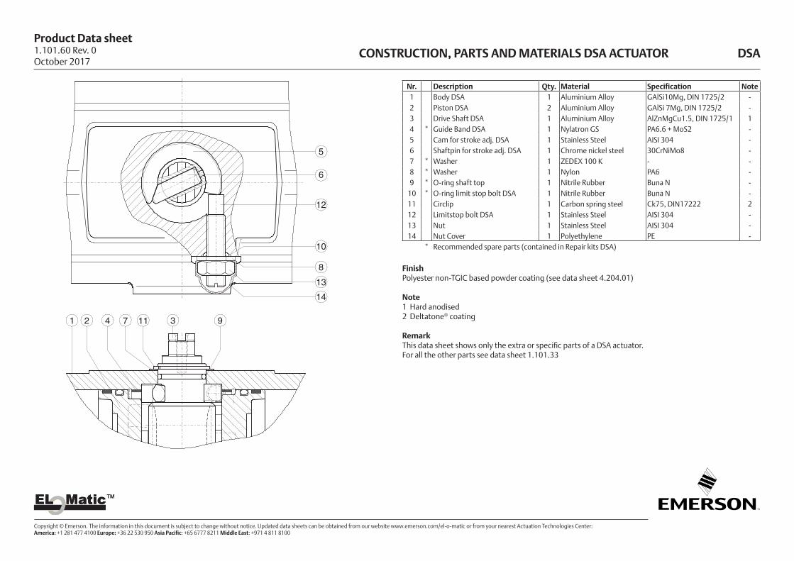
CONSTRUCTION, PARTS AND MATERIALS DSA ACTUATOR DSA
5
6
8
10
12
13
14
1 2 34 7 911
Nr. Description Qty. Material Specification Note1 Body DSA 1 Aluminium Alloy GAlSi10Mg, DIN 1725/2 -2 Piston DSA 2 Aluminium Alloy GAlSi 7Mg, DIN 1725/2 -3 Drive Shaft DSA 1 Aluminium Alloy AlZnMgCu1.5, DIN 1725/1 14 * Guide Band DSA 1 Nylatron GS PA6.6 + MoS2 -5 Cam for stroke adj. DSA 1 Stainless Steel AISI 304 -6 Shaftpin for stroke adj. DSA 1 Chrome nickel steel 30CrNiMo8 -7 * Washer 1 ZEDEX 100 K - -8 * Washer 1 Nylon PA6 -9 * O-ring shaft top 1 Nitrile Rubber Buna N -
10 * O-ring limit stop bolt DSA 1 Nitrile Rubber Buna N -11 Circlip 1 Carbon spring steel Ck75, DIN17222 212 Limitstop bolt DSA 1 Stainless Steel AISI 304 -13 Nut 1 Stainless Steel AISI 304 -14 Nut Cover 1 Polyethylene PE -
* Recommended spare parts (contained in Repair kits DSA)
Finish Polyester non-TGIC based powder coating (see data sheet 4.204.01)
Note 1 Hard anodised2 Deltatone® coating
RemarkThis data sheet shows only the extra or specific parts of a DSA actuator. For all the other parts see data sheet 1.101.33
1.101.60 Rev. 0October 2017
Product Data sheet
Copyright © Emerson. The information in this document is subject to change without notice. Updated data sheets can be obtained from our website www.emerson.com/el-o-matic or from your nearest Actuation Technologies Center: America: +1 281 477 4100 Europe: +36 22 530 950 Asia Pacific: +65 6777 8211 Middle East: +971 4 811 8100
EL MaticTMEL MaticTM
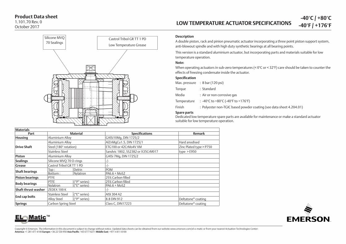
-40°C / +80°C-40°F / +176°FLOW TEMPERATURE ACTUATOR SPECIFICATIONS
Silicone MVQ 70 Sealings
Castrol Tribol GR TT 1 PD
Low Temperature Grease
MaterialsPart Material Specifications Remark
Housing Aluminium Alloy GAlSi10Mg, DIN 1725/2
Drive ShaftAluminium Alloy AlZnMgCu1.5, DIN 1725/1 Hard anodisedSteel (180° rotation) ETG100 or 42CrMo4V XM Zinc Plated type > P750Stainless Steel Sandvic 1802, SS2382 or X35CrM017 type > E950
Piston Aluminium Alloy GAlSi 7Mg, DIN 1725/2Sealings Silicone MVQ 70 O-rings -/-Grease Castrol Tribol GR TT 1 PD -/-
Shaft bearings Top : Delrin POMBottom : Nylatron PA6.6 + MoS2
Piston bearings PTFE 25% Carbon filled
Body bearings PTFE (“P” series) 25% Carbon filled Nylatron (“E” series) PA6.6 + MoS2
Shaft thrust washer ZEDEX 100 K -/-
End cap boltsStainless Steel (“E” series) AISI 304 A2Alloy Steel (“P” series) 8.8 DIN 912 Deltatone® coating
Springs Carbon Spring Steel Class C, DIN17223 Deltatone® coating
DescriptionA double piston, rack and pinion pneumatic actuator incorporating a three point piston support system, anti-blowout spindle and with high duty synthetic bearings at all bearing points.
This version is a standard aluminium actuator, but incorporating parts and materials suitable for low temperature operation.
Note:When operating actuators in sub-zero temperatures (< 0°C or < 32°F) care should be taken to counter the effects of freezing condensate inside the actuator.
SpecificationMax. pressure : 8 bar (120 psi)
Torque : Standard
Media : Air or non corrosive gas
Temperature : -40°C to +80°C (-40°F to +176°F)
Finish : Polyester non-TGIC based powder coating (see data sheet 4.204.01)
Spare partsDedicated low temperature spare parts are available for maintenance or make a standard actuator suitable for low temperature operation.
1.101.70 Rev. 0October 2017

Product Data sheet
Copyright © Emerson. The information in this document is subject to change without notice. Updated data sheets can be obtained from our website www.emerson.com/el-o-matic or from your nearest Actuation Technologies Center: America: +1 281 477 4100 Europe: +36 22 530 950 Asia Pacific: +65 6777 8211 Middle East: +971 4 811 8100
EL MaticTMEL MaticTM
HIGH TEMPERATURE ACTUATOR SPECIFICATIONS-20°C / +120°C
-4°F / +248°F
DescriptionA double piston, rack and pinion pneumatic actuator incorporating a three point piston support system, anti-blowout spindle and with high duty synthetic bearings at all bearing points.
This version is a standard aluminium actuator, but incorporating parts and materials suitable for high temperature operation.
SpecificationMax. pressure : 8 bar (120 psi)
Torque : Standard
Media : Air or non corrosive gas
Temperature : -20°C to +120°C (-4°F to +248°F)
Spare partsDedicated high temperature spare parts are available for maintenance or make a standard actuator suitable for high temperature operation.
MaterialsPart Material Specifications Remark
Housing Aluminium Alloy GAlSi10Mg, DIN 1725/2
Drive ShaftAluminium Alloy AlZnMgCu1.5, DIN 1725/1 Hard anodisedSteel (180° rotation) ETG100 or 42CrMo4V XM Zinc Plated type > P750Stainless Steel Sandvic 1802, SS2382 or X35CrM017 type > E950
Piston Aluminium Alloy GAlSi 7Mg, DIN 1725/2Sealings Viton FPM O-rings -/-Grease Castrol High Temperature grease (or equal) -/-
Shaft bearings Top : Delrin POMBottom : Nylatron PA6.6 + MoS2
Piston bearings PTFE 25% Carbon filled
Body bearings PTFE (“P” series) 25% Carbon filled Nylatron (“E” series) PA6.6 + MoS2
Shaft thrust washer ZEDEX 100 K -/-
End cap boltsStainless Steel (“E” series) AISI 304 A2Alloy Steel (“P” series) 8.8 DIN 912 Deltatone® coating
Springs Carbon Spring Steel Class C, DIN17223 Deltatone® coating
Viton
FPM SealingsCastrol High Temperature grease
(or equal)
1.101.71 Rev. 0October 2017

Product Data sheet
Copyright © Emerson. The information in this document is subject to change without notice. Updated data sheets can be obtained from our website www.emerson.com/el-o-matic or from your nearest Actuation Technologies Center: America: +1 281 477 4100 Europe: +36 22 530 950 Asia Pacific: +65 6777 8211 Middle East: +971 4 811 8100
EL MaticTMEL MaticTM
INSTALLATION OF SPRINGS OF P-SERIES ACTUATOR P
4 SPRINGS 6 SPRINGS 8 SPRINGS
10 SPRINGS 12 SPRINGS 14 SPRINGS
SPRING
4.201 Rev. 0October 2017

Product Data sheet
Copyright © Emerson. The information in this document is subject to change without notice. Updated data sheets can be obtained from our website www.emerson.com/el-o-matic or from your nearest Actuation Technologies Center: America: +1 281 477 4100 Europe: +36 22 530 950 Asia Pacific: +65 6777 8211 Middle East: +971 4 811 8100
EL MaticTMEL MaticTM
SPRING SET No. 4inner springouter spring
SPRING SET No. 1inner spring
SPRING SET No. 2mid spring
SPRING SET No. 5mid springouter spring
SPRING SET No. 6inner springmid springouter spring
SPRING SET No. 3inner springmid spring
INSTALLATION OF SPRINGS OF E-SERIES ACTUATOR E4.202 Rev. 0October 2017
Product Data sheet
Copyright © Emerson. The information in this document is subject to change without notice. Updated data sheets can be obtained from our website www.emerson.com/el-o-matic or from your nearest Actuation Technologies Center: America: +1 281 477 4100 Europe: +36 22 530 950 Asia Pacific: +65 6777 8211 Middle East: +971 4 811 8100
EL MaticTMEL MaticTM
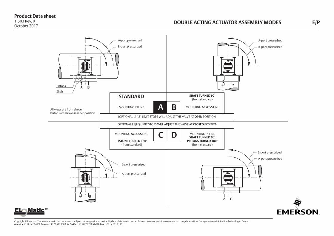
A B
A B
A B
A B
A-port pressurized
B-port pressurized
Pistons
Shaft
A-port pressurized
B-port pressurized
B-port pressurized
A-port pressurized
B-port pressurized
A-port pressurized
DOUBLE ACTING ACTUATOR ASSEMBLY MODES E/P
B
SHAFT TURNED 90°(from standard)
STANDARD
DC
MOUNTING ACROSS LINE
MOUNTING IN LINE
MOUNTING IN LINE
MOUNTING ACROSS LINESHAFT TURNED 90°
PISTONS TURNED 180°(from standard)
PISTONS TURNED 180° (from standard)
(OPTIONAL L1/LF) LIMIT STOPS WILL ADJUST THE VALVE AT OPEN POSITION
(OPTIONAL L1/LF) LIMIT STOPS WILL ADJUST THE VALVE AT CLOSED POSITION
All views are from abovePistons are shown in inner position
A
1.503 Rev. 0October 2017

Product Data sheet
Copyright © Emerson. The information in this document is subject to change without notice. Updated data sheets can be obtained from our website www.emerson.com/el-o-matic or from your nearest Actuation Technologies Center: America: +1 281 477 4100 Europe: +36 22 530 950 Asia Pacific: +65 6777 8211 Middle East: +971 4 811 8100
EL MaticTMEL MaticTM
SPRING RETURN ACTUATOR ASSEMBLY MODES E/P
A B
A B
A B
A B
SPRING TO OPEN (ROTATION CCW)
B
SHAFT TURNED 90°(from standard)
STANDARD
DC
MOUNTING ACROSS LINE
MOUNTING IN LINE
MOUNTING IN LINE
MOUNTING ACROSS LINESHAFT TURNED 90°
PISTONS TURNED 180°(from standard)
PISTONS TURNED 180° (from standard)
SPRING TO CLOSE (ROTATION CW)
A-port pressurized
Spring stroke
Springs
Pistons
Shaft
A-port pressurized
Spring stroke
A-port pressurized
Spring stroke
Spring stroke
A-port pressurized
AAll views are from abovePistons are shown in inner position
1.504 Rev. 0October 2017
Product Data sheet
Copyright © Emerson. The information in this document is subject to change without notice. Updated data sheets can be obtained from our website www.emerson.com/el-o-matic or from your nearest Actuation Technologies Center: America: +1 281 477 4100 Europe: +36 22 530 950 Asia Pacific: +65 6777 8211 Middle East: +971 4 811 8100
EL MaticTMEL MaticTM
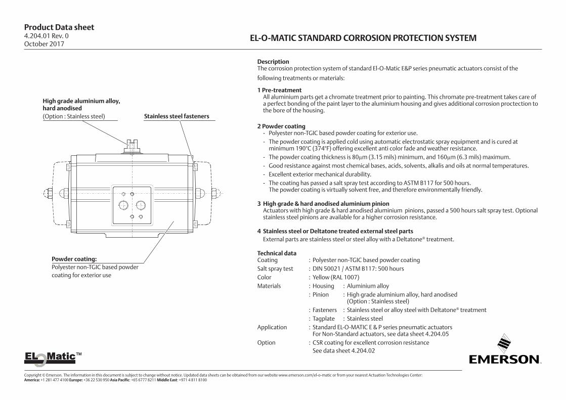
DescriptionThe corrosion protection system of standard El-O-Matic E&P series pneumatic actuators consist of the
following treatments or materials:
1 Pre-treatment All aluminium parts get a chromate treatment prior to painting. This chromate pre-treatment takes care of
a perfect bonding of the paint layer to the aluminium housing and gives additional corrosion proctection to the bore of the housing.
2 Powder coating - Polyester non-TGIC based powder coating for exterior use. - The powder coating is applied cold using automatic electrostatic spray equipment and is cured at
minimum 190°C (374°F) offering excellent anti color fade and weather resistance. - The powder coating thickness is 80µm (3.15 mils) minimum, and 160µm (6.3 mils) maximum. - Good resistance against most chemical bases, acids, solvents, alkalis and oils at normal temperatures. - Excellent exterior mechanical durability. - The coating has passed a salt spray test according to ASTM B117 for 500 hours.
The powder coating is virtually solvent free, and therefore environmentally friendly.
3 High grade & hard anodised aluminium pinion Actuators with high grade & hard anodised aluminium pinions, passed a 500 hours salt spray test. Optional
stainless steel pinions are available for a higher corrosion resistance.
4 Stainless steel or Deltatone treated external steel parts External parts are stainless steel or steel alloy with a Deltatone® treatment.
Technical dataCoating : Polyester non-TGIC based powder coating Salt spray test : DIN 50021 / ASTM B117: 500 hoursColor : Yellow (RAL 1007) Materials : Housing : Aluminium alloy : Pinion : High grade aluminium alloy, hard anodised
(Option : Stainless steel) : Fasteners : Stainless steel or alloy steel with Deltatone® treatment : Tagplate : Stainless steelApplication : Standard EL-O-MATIC E & P series pneumatic actuators
For Non-Standard actuators, see data sheet 4.204.05Option : CSR coating for excellent corrosion resistance
See data sheet 4.204.02
High grade aluminium alloy, hard anodised(Option : Stainless steel) Stainless steel fasteners
Powder coating:Polyester non-TGIC based powder coating for exterior use
EL-O-MATIC STANDARD CORROSION PROTECTION SYSTEM 4.204.01 Rev. 0October 2017
Product Data sheet
Copyright © Emerson. The information in this document is subject to change without notice. Updated data sheets can be obtained from our website www.emerson.com/el-o-matic or from your nearest Actuation Technologies Center: America: +1 281 477 4100 Europe: +36 22 530 950 Asia Pacific: +65 6777 8211 Middle East: +971 4 811 8100
EL MaticTMEL MaticTM
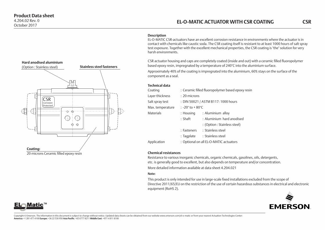
DescriptionEL-O-MATIC CSR-actuators have an excellent corrosion resistance in environments where the actuator is in contact with chemicals like caustic soda. The CSR coating itself is resistant to at least 1000 hours of salt spray test exposure. Together with the excellent mechanical properties, the CSR coating is "the" solution for very harsh environments.
CSR actuator housing and caps are completely coated (inside and out) with a ceramic filled fluoropolymer based epoxy resin, impregnated by a temperature of 240°C into the aluminium surface.
Approximately 40% of the coating is impregnated into the aluminium, 60% stays on the surface of the component as a seal.
Technical dataCoating : Ceramic filled fluoropolymer based epoxy resin
Layer thickness : 20 microns
Salt spray test : DIN 50021 / ASTM B117: 1000 hours
Max. temperature : -20° to + 80°C
Materials : Housing : Aluminium alloy
: Shaft : Aluminium hard anodised
: (Option : Stainless steel)
: Fasteners : Stainless steel
: Tagplate : Stainless steel
Application : Optional on all EL-O-MATIC actuators
Chemical resistancesResistance to various inorganic chemicals, organic chemicals, gasolines, oils, detergents, etc. is generally good to excellent, but also depends on temperature and/or concentration.
More detailed information available at data sheet 4.204.021
Note:
This product is only intended for use in large-scale fixed installations excluded from the scope of Directive 2011/65/EU on the restriction of the use of certain hazardous substances in electrical and electronic equipment (RoHS 2).
EL-O-MATIC ACTUATOR WITH CSR COATING CSR
Hard anodised aluminium (Option : Stainless steel) Stainless steel fasteners
Coating:20 microns Ceramic filled epoxy resin
4.204.02 Rev. 0October 2017
CSRCorrosionProtected

Product Data sheet
Copyright © Emerson. The information in this document is subject to change without notice. Updated data sheets can be obtained from our website www.emerson.com/el-o-matic or from your nearest Actuation Technologies Center: America: +1 281 477 4100 Europe: +36 22 530 950 Asia Pacific: +65 6777 8211 Middle East: +971 4 811 8100
EL MaticTMEL MaticTM
CHEMICAL RESISTANCE LIST FOR CSR COATING CSR
Note: This list has been composed with great care. However, EL -O - MATIC
cannot be held responsible, either for any errors in this list or for
their consequences.
Because of continued testing this list is subject to change without
notice.
Inorganic chemicals1 Ammonium hydroxide (10%) 2 Nitric acid (10%)1 Calcium chloride (~50%) 3 Nitric acid (50%)3 Chlorine 1 Hydrochloric acid (10%)3 Chromic acid 1 Hydrochloric acid (concentrated)3 Hydrofluoric acid (50%) 1 Sulphuric acid (50%)1 Caustic potash solution (10%) 3 Sulphuric acid (concentrated)1 Sodium hypochlorite (saturated) 2 Sulphur dioxide1 Caustic soda solution (10%) 1 Sulphur hexafluoride1 Caustic soda solution (saturated) 2 Nitric oxide1 Phosphoric acid (10%) 1 Hydrogen peroxide (100%)1 Phosphoric acid (50%)Organic chemicals 3 Acetone 1 Glycerine3 Acetonitrile 1 Hexane3 Aniline 1 Isooctane2 Benzene 1 Isopropanol1 n-Butanol 1 Methanol3 Butyl acetate 3 Methylene chloride3 Chlorobenzene 3 Methyl ethyl ketone3 Chloroforme 3 N.N-Dimethylformamide3 o-Chlorophenol 3 N-Methylpyrrolidon1 Cyclohexane 1 Oxalic acid3 Cyclohexanone 1 Perchloroethylene3 1,2-Dichloroethane 1 Petroleum ether2 Diethyl ether 3 Phenol2 Dioxane 1 Carbon bisulphide1 Glacial acetic acid 1 Turpentine1 Ethanol 2 Tetrachloroethane3 Ethyl acetate 2 1,1,1-Trichloroethane1 Ethylene glycol 1 Tetrachloromethane1 Formaldehyde 3 Trichloroethylene2 Freon 11 2 Toluene2 Freon 22 1 Xylene
Fuels/lubricants1 Two-star petrol (50°C)1 Four-star petrol (50°C)1 Fuel M 15 (50°C)1 Diesel oil1 Kerosene1 to 2 Hypoid bevel gear oil Shell Spirax HD 90 (150°C)1 Transmission oil Shell Spirax MA 80 (150°C)
Chemicals1 Automatic transmission fluid Shell Dextra 11D 20-137 (150°C)1 Engine oil, mineral, Mihag 1500-40 (150°C)1 Engine oil, synthetic, Mobil SHC 10 W-403 Brake fluid Hydraulan DOT 41 Roller bearing grease DIN 51 825
Technical detergents2 Genkeene2 1,1,1- Trichloroethane2 Triklone A2 Perchloroethylene
Miscellaneous fluids1 Glysantin (BASF)/water1 Plasticizer DOP1 Suds1 Washing-up liquids1 Household detergents1 Linseed oil1 Milk1 Soapsuds1 Silicone oils
1 Excellent2 Limited resistance; it is recommended to perform field tests under the specified conditions.3 Not recommended
4.204.021 Rev. 0October 2017
Product Data sheet
Copyright © Emerson. The information in this document is subject to change without notice. Updated data sheets can be obtained from our website www.emerson.com/el-o-matic or from your nearest Actuation Technologies Center: America: +1 281 477 4100 Europe: +36 22 530 950 Asia Pacific: +65 6777 8211 Middle East: +971 4 811 8100
EL MaticTMEL MaticTM
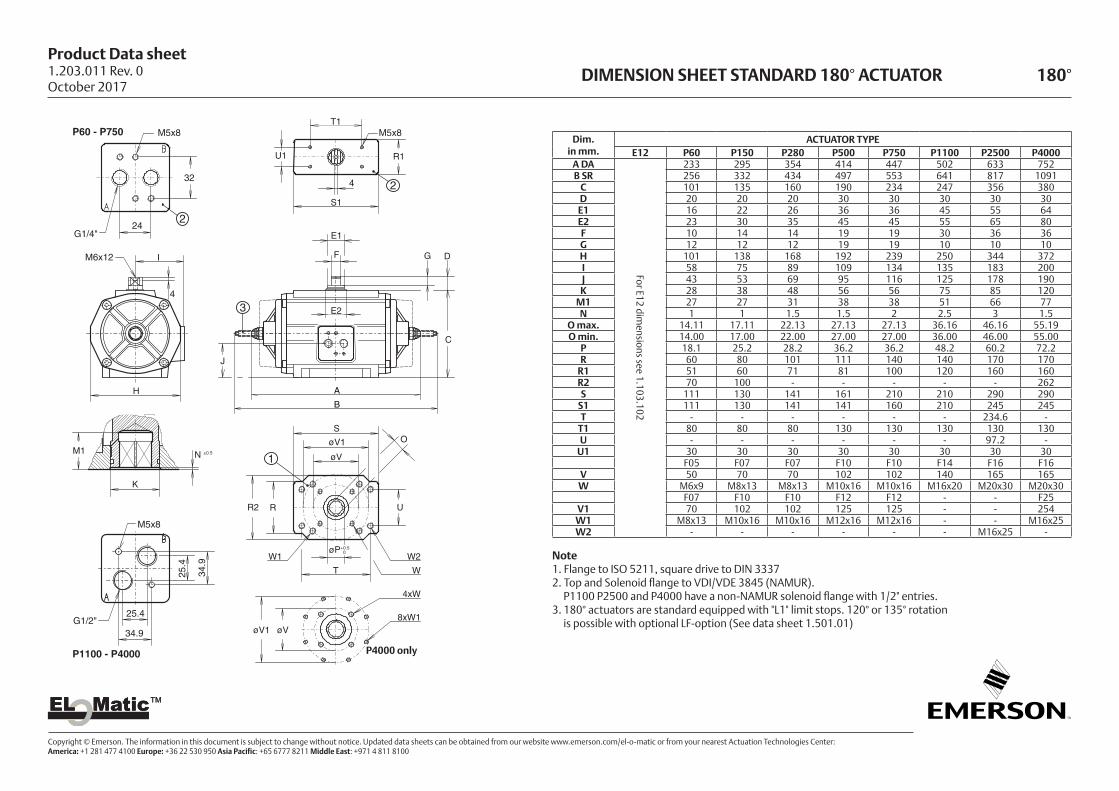
DIMENSION SHEET STANDARD 180° ACTUATOR 180°
Dim.in mm.
ACTUATOR TYPEE12 P60 P150 P280 P500 P750 P1100 P2500 P4000
A DA
For E12 dimensions see 1.103.102
233 295 354 414 447 502 633 752B SR 256 332 434 497 553 641 817 1091
C 101 135 160 190 234 247 356 380D 20 20 20 30 30 30 30 30E1 16 22 26 36 36 45 55 64E2 23 30 35 45 45 55 65 80F 10 14 14 19 19 30 36 36G 12 12 12 19 19 10 10 10H 101 138 168 192 239 250 344 372I 58 75 89 109 134 135 183 200J 43 53 69 95 116 125 178 190K 28 38 48 56 56 75 85 120
M1 27 27 31 38 38 51 66 77N 1 1 1.5 1.5 2 2.5 3 1.5
O max. 14.11 17.11 22.13 27.13 27.13 36.16 46.16 55.19O min. 14.00 17.00 22.00 27.00 27.00 36.00 46.00 55.00
P 18.1 25.2 28.2 36.2 36.2 48.2 60.2 72.2R 60 80 101 111 140 140 170 170
R1 51 60 71 81 100 120 160 160R2 70 100 - - - - - 262S 111 130 141 161 210 210 290 290
S1 111 130 141 141 160 210 245 245T - - - - - - 234.6 -
T1 80 80 80 130 130 130 130 130U - - - - - - 97.2 -
U1 30 30 30 30 30 30 30 30F05 F07 F07 F10 F10 F14 F16 F16
V 50 70 70 102 102 140 165 165W M6x9 M8x13 M8x13 M10x16 M10x16 M16x20 M20x30 M20x30
F07 F10 F10 F12 F12 - - F25V1 70 102 102 125 125 - - 254W1 M8x13 M10x16 M10x16 M12x16 M12x16 - - M16x25W2 - - - - - - M16x25 -
Note1. Flange to ISO 5211, square drive to DIN 33372. Top and Solenoid flange to VDI/VDE 3845 (NAMUR).
P1100 P2500 and P4000 have a non-NAMUR solenoid flange with 1/2" entries.3. 180° actuators are standard equipped with "L1" limit stops. 120° or 135° rotation
is possible with optional LF-option (See data sheet 1.501.01)
P60 - P750
24
32
M5x8
G1/4"
IM6x12
4
H
K
M1 N ±0.5
øV1
4xW
øV8xW1
W1øP+0.5
0
W
W2
T
O
RR2
S
øV
øV1
U
B
A
4
U1
T1
R1
S1
M5x8
E1
F
E2
J
G D
C
3
P1100 - P4000
M5x8
25.4
34.9
25.4G1/2"
34.9
1
2
2
P4000 only
1.203.011 Rev. 0October 2017
Product Data sheet
Copyright © Emerson. The information in this document is subject to change without notice. Updated data sheets can be obtained from our website www.emerson.com/el-o-matic or from your nearest Actuation Technologies Center: America: +1 281 477 4100 Europe: +36 22 530 950 Asia Pacific: +65 6777 8211 Middle East: +971 4 811 8100
EL MaticTMEL MaticTM
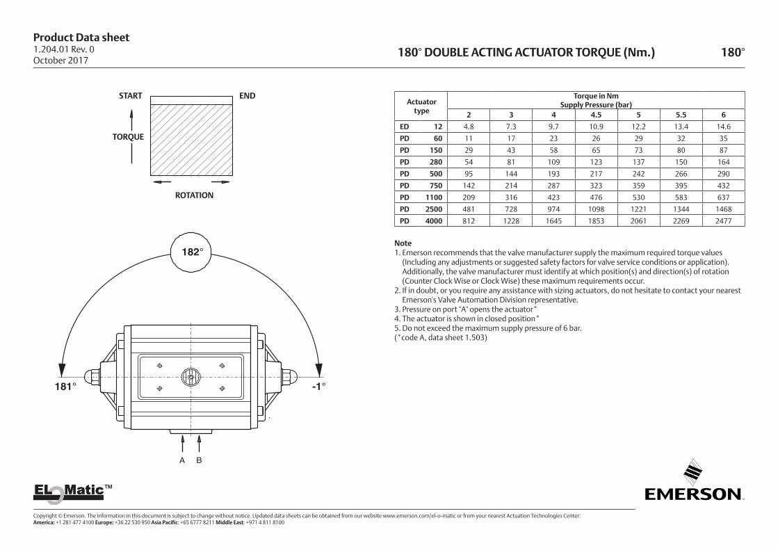
180° DOUBLE ACTING ACTUATOR TORQUE (Nm.) 180°
Actuatortype
Torque in NmSupply Pressure (bar)
2 3 4 4.5 5 5.5 6
ED 12 4.8 7.3 9.7 10.9 12.2 13.4 14.6
PD 60 11 17 23 26 29 32 35
PD 150 29 43 58 65 73 80 87
PD 280 54 81 109 123 137 150 164
PD 500 95 144 193 217 242 266 290
PD 750 142 214 287 323 359 395 432
PD 1100 209 316 423 476 530 583 637
PD 2500 481 728 974 1098 1221 1344 1468
PD 4000 812 1228 1645 1853 2061 2269 2477
Note1. Emerson recommends that the valve manufacturer supply the maximum required torque values
(Including any adjustments or suggested safety factors for valve service conditions or application). Additionally, the valve manufacturer must identify at which position(s) and direction(s) of rotation
(Counter Clock Wise or Clock Wise) these maximum requirements occur. 2. If in doubt, or you require any assistance with sizing actuators, do not hesitate to contact your nearest
Emerson's Valve Automation Division representative.3. Pressure on port "A" opens the actuator*4. The actuator is shown in closed position* 5. Do not exceed the maximum supply pressure of 6 bar.(*code A, data sheet 1.503)
A B
182°
181° -1°
TORQUE
START END
ROTATION
1.204.01 Rev. 0October 2017

Product Data sheet
Copyright © Emerson. The information in this document is subject to change without notice. Updated data sheets can be obtained from our website www.emerson.com/el-o-matic or from your nearest Actuation Technologies Center: America: +1 281 477 4100 Europe: +36 22 530 950 Asia Pacific: +65 6777 8211 Middle East: +971 4 811 8100
EL MaticTMEL MaticTM
180° SPRING RETURN ACTUATOR TORQUE (Nm.) 180°
Note1. Emerson recommends that the valve manufacturer supply the maximum required torque values
(Including any adjustments or suggested safety factors for valve service conditions or application). Additionally, the valve manufacturer must identify at which position(s) and direction(s) of rotation
(Counter Clock Wise or Clock Wise) these maximum requirements occur. 2. If in doubt, or you require any assistance with sizing actuators, do not hesitate to contact your nearest
Emerson's Valve Automation Division representative.3. Pressure on port "A" opens the actuator*4. The actuator is shown in closed position* 5. Do not exceed the maximum supply pressure of 6 bar.(*code A, data sheet 1.504)
Spring nr. Air Stroke (Nm) SpringStrokeSUPPLY PRESSURE
Actuatortype
3 3.5 4 4.5 5 5.5 6 (Nm)C D C D C D C D C D C D C D E F
ES 12 2 - - 3.8 1.1 5.2 2.4 6.5 3.7 7.8 5.0 9.1 6.3 10.4 7.6 7.1 4.5PE 60 8 9 4 12 6 15 9 18 12 21 15 24 18 27 21 13 7
10 - - 10 3 13 6 16 9 19 12 22 15 25 18 16 912 - - - - 11 3 14 5 17 8 20 11 23 14 19 1114 - - - - - - 12 2 15 5 18 8 21 11 22 12
PE 150 8 24 12 32 19 39 27 46 34 54 41 61 49 68 56 29 1710 20 4 27 12 34 19 42 26 49 34 56 41 64 48 36 2112 - - 22 4 30 11 37 19 44 26 52 33 59 40 44 2514 - - - - 25 3 32 11 40 18 47 25 54 33 51 30
PE 280 8 43 9 57 23 71 37 85 51 99 65 112 78 126 92 67 3410 - - 48 5 61 19 75 33 89 47 103 60 117 74 84 4312 - - - - - - 66 15 80 29 93 42 107 56 101 5114 - - - - - - - - 70 11 84 24 98 38 118 60
PE 500 8 - - 112 31 136 56 160 80 185 105 209 129 - - 128 5110 - - - - 122 22 146 46 171 70 195 95 219 119 160 6412 - - - - - - - - 156 36 181 61 205 85 192 7714 - - - - - - - - - - 167 26 191 51 224 89
PE 750 8 134 29 170 66 206 102 242 138 279 175 - - - - 173 7210 - - 150 20 186 56 222 92 259 128 295 165 331 201 216 9112 - - - - - - 202 46 239 82 275 119 311 155 259 10914 - - - - - - - - 218 36 255 72 291 109 302 127
PE1100 8 190 74 244 128 297 181 351 235 404 288 458 342 - - 226 11310 - - 212 68 266 121 319 175 373 228 426 282 480 335 282 14112 - - - - 234 61 288 114 341 168 395 221 448 275 339 17014 - - - - - - 257 54 310 107 364 161 417 214 395 198
PS2500 8 356 160 479 283 602 406 724 528 847 651 970 774 1093 897 528 33210 - - 387 142 510 265 632 387 755 510 878 633 1001 756 660 41412 - - - - 417 123 540 246 663 369 786 492 909 615 792 49714 - - - - - - 448 105 571 228 694 351 816 473 924 580
PS4000 8 606 276 814 484 1023 692 1231 900 1439 1108 1647 1316 1855 1524 891 56010 - - 659 246 867 454 1075 662 1283 870 1492 1078 1700 1286 1114 69912 - - - - 712 216 920 424 1128 632 1336 840 1544 1048 1337 83914 - - - - - - 764 186 973 394 1181 602 1389 810 1560 979
D E181°
F C-1°
A B
182°
SPRING STROKEAIR STROKE
FEnd
RotationClockwise
DEnd
RotationCounter Clockwise
CStart
Torque
EStart
1.204.02 Rev. 0October 2017

EL MaticTMEL MaticTM
World Area Configuration Centers (WACC) offer sales support, service, inventory and commissioning to our global customers. Choose the WACC or sales office nearest you:
www.emerson.com/el-o-matic
©2018 Emerson. All rights reserved.
The Emerson logo is a trademark and service mark of Emerson Electric Co. EL-O-MaticTM is a mark of one of the Emerson family of companies. All other marks are property of their respective owners.
The contents of this publication are presented for information purposes only, and while every effort has been made to ensure their accuracy, they are not to be construed as warranties or guarantees, express or implied, regarding the products or services described herein or their use or applicability. All sales are governed by our terms and conditions, which are available on request. We reserve the right to modify or improve the designs or specifi cations of our products at any time without notice.
NORTH & SOUTH AMERICA
19200 Northwest FreewayHouston TX 77065USAT +1 281 477 4100
Av. Hollingsworth 325 Iporanga Sorocaba SP 18087-105BrazilT +55 15 3413 8888
ASIA PACIFIC
No. 9 Gul Road#01-02 Singapore 629361T +65 6777 8211
No. 1 Lai Yuan RoadWuqing Development AreaTianjin 301700P. R. ChinaT +86 22 8212 3300
MIDDLE EAST & AFRICA
P. O. Box 17033Jebel Ali Free ZoneDubaiT +971 4 811 8100
P. O. Box 10305Jubail 31961Saudi ArabiaT +966 3 340 8650
24 Angus CrescentLongmeadow Business Estate East P.O. Box 6908 Greenstone 1616 Modderfontein Extension 5South AfricaT +27 11 451 3700
EUROPE
Holland Fasor 6Székesfehérvár 8000HungaryT +36 22 53 09 50
Strada Biffi 16529017 Fiorenzuola d’Arda (PC)ItalyT +39 0523 944 411
For complete list of sales and manufacturing sites, please visit www.emerson.com/actuationtechnologieslocations Or contact us at [email protected]